1
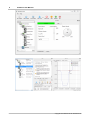
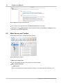
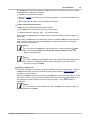
User Manual
Doc Rev 1.0.13 - 30.01.2014
Kickdrive V1.9.80
www.kickdrive.de
2
Kickdrive User Manual
Table of Contents
1 Copyright
4
2 About This Manual
5
1 Symbols
...................................................................................................................................
Used
5
2 Terms
...................................................................................................................................
Used
5
3 Safety
7
1 Intended
...................................................................................................................................
Use
7
2 Safety
...................................................................................................................................
Notices
7
4 Overview
7
5 Installation
9
6 Using Kickdrive
9
1 Getting
...................................................................................................................................
Started
9
2 Main
...................................................................................................................................
Screen and Toolbar
10
3 User
...................................................................................................................................
Level
11
4 Projects
...................................................................................................................................
and Templates
12
5 Editing
...................................................................................................................................
the Module Tree
14
6 Runtime
...................................................................................................................................
Generator
14
7 Kickdrive Modules
15
1 CAN
...................................................................................................................................
Interface
15
CAN Monitor
......................................................................................................................................................... 17
CAN Sender
......................................................................................................................................................... 18
2 CANopen
...................................................................................................................................
Drive
20
Setup
......................................................................................................................................................... 20
Object Editor
......................................................................................................................................................... 21
Script
......................................................................................................................................................... 22
Firm w are ......................................................................................................................................................... 22
3 CANopen
...................................................................................................................................
Node
23
CANopen Node
.........................................................................................................................................................
- Edit Mode
24
CANopen Node
.........................................................................................................................................................
- UI Form at
24
4 Network
...................................................................................................................................
Manager
26
5 Scope
................................................................................................................................... 27
Scope - Getting
.........................................................................................................................................................
Started
27
Configuration
......................................................................................................................................................... 28
Recording.........................................................................................................................................................
Data
29
Plot
......................................................................................................................................................... 29
Copyright 2014 www.fuh-edv.de / www.fullmo.de
Table of Contents
Trigger
3
......................................................................................................................................................... 30
6 UI ...................................................................................................................................
Panel
31
UI Panel - Getting
.........................................................................................................................................................
Started
32
UI Form at .........................................................................................................................................................
Definition
32
Node IDs and
.........................................................................................................................................................
Multi-Node Panels
36
Project and
.........................................................................................................................................................
UI Files / Advanced User Interfaces
36
7 Automation
................................................................................................................................... 37
Setup
......................................................................................................................................................... 37
Copyright 2014 www.fuh-edv.de / www.fullmo.de
4
1
Kickdrive User Manual
Copyright
Copyright 2014 Flachmann und Heggelbacher GbR ( www.fuh-edv.de ) and fullmo GmbH
( www.fullmo.de )
All rights reserved. No parts of this work may be reproduced in any form or by any means without
the written permission of the publisher.
Trademarks
Products that are referred to in this document may be either trademarks and/or registered
trademarks of their respective owners. The publisher and the author make no claim to these
trademarks.
Microsoft and Windows are either registered trademarks or trademarks of Microsoft Corporation in
the United States and/or other countries.
Disclaimer
While every precaution has been taken in the preparation of this document, the publisher and the
author assume no responsibility for errors or omissions, or for damages resulting from the use of
information contained in this document or from the use of programs and source code that may
accompany it. In no event shall the publisher and the author be liable for any loss of profit or any
other commercial damage caused or alleged to have been caused directly or indirectly by this
document.
Contact
Technical Support for Kickdrive :
[email protected]
Flachmann & Heggelbacher GbR
Waldkirchbogen 27
D-82061 Neuried, Germany
www.fuh-edv.de
Any information or support related to fullmo or ebmpapst drive products (positioning drives, linear
drives, automation applications):
[email protected]
Fullmo GmbH
Robert-Bosch-Straße 12
D-88677 Markdorf, Germany
www.fullmo.de
Copyright 2014 www.fuh-edv.de / www.fullmo.de
About This Manual
2
About This Manual
2.1
Symbols Used
The following symbols are used in this document:
Warning
As defined by these operating instructions and the danger notices on the products,
death, severe bodily injury or considerable damage to property could result if the
appropriate safety measures are not taken.
Notice
Important information about the product or part of the operating instructions.
2.2
Terms Used
Qualified personnel
Personnel who are familiar with the installation, assembly, commissioning and operation of the
product and are qualified to carry out the respective activities.
CAN (CAN-Bus)
Controller Area Network. Field bus design according to ISO 11898-1.
CANopen
CAN-based higher layer protocol designed for use in motion-oriented machine control networks, as
maintained by http://www.can-cia.org.
CAN Interface
Accessory to connect the PC with the CAN bus network. Usually this is a CAN-USB interface, but
other options (e.g. CAN-NET via Ethernet TCP) can be available.
Node
CANopen device, identified by a Node ID in the range of 1..127.
CANopen Drive
EC position drive that can be configured and operated using Kickdrive, e.g. ebm-papst ECI series.
Copyright 2014 www.fuh-edv.de / www.fullmo.de
5
6
Kickdrive User Manual
Python
A programming and scripting language under OSI Open Source License, maintained by http://
www.python.org . Kickdrive currently uses the Python 2.6.7 implementation.
Data Object
A device parameter or value that can be read out and/or modified using Kickdrive. For CANopen
devices a data object is referenced by the Node ID, and the object index and subindex. Kickdrive
uses the following standard format for a Data Object ID:
127.1000h.00h (here: Node ID = 127, object index 1000h and subindex 0h)
CANopen object data values are obtained using SDO or PDO transfer.
SDO Service Data Object
CANopen SDO transfers are used for low priority reading and writing of device parameters and
objects. SDO Upload (read from device) and SDO Download (write to device) specifications define
different standard methods of reading and writing different types of data, including optimized transfers
for large blocks of data.
PDO Process Data Object
CANopen devices produce or consume PDO CAN frames. They are used for fast data transfer of
critical process data. Before using PDO transfer, the CANopen device must be configured, i.e. the
content of the PDO object must be defined (PDO Mapping). Two types of PDOs are defined for
CANopen:
Transmit PDO (TPDO) - process data produced by the device node, e.g. status and position
information.
Receive PDO (RPDO) - process data consumed by the device node, e.g. control command.
XDD / XDC
XML Device Description File (.xdd) / XML Device Configuration File (.xdc).
XDD files contain a dictionary of device functions and parameters and supersede the classic .eds
files (Electronic DataSheet).
XDC file in addition contain parameter values for device configuration and supersede the .dcf file
format (Device Configuration File).
Qt Quick / QML
Qt Quick is a new user interface (UI) technology and development kit for creating rich, attractive user
interfaces in minimum time.
QML is a declarative user interface language based on Javascript. It describes how user interface
elements look and how they behave.
Kickdrive projects can make use of Qt Quick technology to build custom designed screens and
attractive end user applications.
Copyright 2014 www.fuh-edv.de / www.fullmo.de
Safety
3
Safety
3.1
Intended Use
7
This software is intended for the commissioning and service of position drives and other motionoriented machine control units. This software accesses the devices via a high-level application layer
protocol such as CANopen.
3.2
Safety Notices
Warning
For all commissioning and service tasks, please refer to the technical documentation of
your drive unit or automation device controlled by this software. All works must be
performed by Qualified Personnel familiar with the drive units or devices.
4
Overview
Kickdrive is a modular PC software platform that can be used for a variety of configuration,
commissioning and service tasks.
It is highly flexible and uses application-specific project and template files to present the user with
exactly the functions and controls needed for a specific task. For example, a field engineer could
work with a Kickdrive project that performs exclusively application-specific service tasks, e.g. a drive
firmware update. Meanwhile, developers and application engineers could work with a scalable, fully
flexible interface, making use of the full range of Kickdrive's functionality. For example:
Commissioning and configuring field bus nodes, like drive units or controllers.
Field bus monitoring (e.g. generating a CAN Bus trace file, CAN BUS monitor with Find and Filter
functions).
Scope data display: Live display of data from one or several drive parameters, logging to a file,
trigger on specific events.
Custom UI Panels: create, display and control elements for a specific application, e.g. machine
control. Build a simple panel from predefined sliders and dials using simple drag and drop.
Alternatively, create rich smartphone-like user interfaces with your own graphics material and
application specific behavior.
Kickdrive projects are made up of standard modules which serve as building blocks. For example,
the "CAN (USB) Interface" or the "CANopen Drive". For specialized applications (Scope, UI
Panels, ...) additional project templates are available, containing more modules.
Copyright 2014 www.fuh-edv.de / www.fullmo.de
8
Kickdrive User Manual
Copyright 2014 www.fuh-edv.de / www.fullmo.de
Installation
5
9
Installation
The Kickdrive application software is usually distributed in a .exe self-extracting archive file.
Double-click the .exe file to copy the application to a directory on your computer, or a removable
media, e.g. a disk-on-key USB memory stick.
Then start the Kickdrive software by double-clicking on Kickdrive.exe.
Notice
No installation (setup) is required, but please make sure you extracted all files and
folders from the original .zip archive to a location on your PC or removable media.
Notice
Additional device driver installation can be required for hardware accessories like the CAN
Interface (USB-CAN). Driver installation on Windows 8, Windows 7 and other recent
Windows versions is fully automatic when connecting the device for the first time. Please
follow the Windows instructions.
6
Using Kickdrive
6.1
Getting Started
Warning
Do not operate Kickdrive within an automation network where any of the Kickdrive CAN or
CANopen communication could possibly disrupt the normal operation.
Warning
Incorrect wiring or wrong cabling can damage electronic components, including the CAN
Interface, CANopen devices and the PC connected with the CAN Interface.
Connect the CAN Interface to your equipment first, before connecting it to the PC.
Switch on power supply for the CAN nodes.
Connect the CAN Interface to your PC using the USB cable supplied.
Start the Kickdrive software application.
Kickdrive presents a home screen that allows you to pick your specific application or project.
Copyright 2014 www.fuh-edv.de / www.fullmo.de
10
Kickdrive User Manual
Kickdrive Main Screen and Project Selector
Pick a project or an application from the Project Selector list on the right.
Alternatively, use
Open Project to load a Kickdrive Project File (.kickzip or .kickpro) that you
received for your specific application.
6.2
Main Screen and Toolbar
The Kickdrive main screen is divided into three sections:
Kickdrive Main Screen Layout
1 - Menu and Toolbar Area
The menu and toolbar area stays the same for all Kickdrive project.
Main Toolbar Functions
New Project
Opens the Kickdrive Home Project template. Usually, it is a project selector that allows you to
Copyright 2014 www.fuh-edv.de / www.fullmo.de
Using Kickdrive
11
pick your specific application.
Open Project
Opens an existing Kickdrive project (.kickzip or .kickpro) or template (.kicktpl).
Save Project
Saves the currently open project including all configurations and additional files used within the
project.
User Level
Changes the User Level. A password may be required.
Stop Drives
Put all drive units listed in the Module area back to idle mode.
Warning
The Stop Drives function is not an emergency stop device. It cannot perform any
safety or emergency functionality for your drive application. Please ensure that
external emergency stop functions are effective, according to the safety regulations
and requirements of your drive application.
Updates
Downloads the latest version of the application and relevant projects. You need to have login
information in order to download software updates and additional Kickdrive projects and
templates. Please refer to your original Kickdrive distributor or to your supplier for your login
data.
2 - Modules Area
This area shows the Kickdrive Modules available with the currently opened project. Greyed out items
are modules that require a higher User Level for access. Editing the module tree is also possible, but
requires a higher User Level, too.
3 - Content Area
Clicking on a module symbol in the modules area
will open a detailed view of this module or a
specific function (e.g. "CAN Monitor") in the content area
. The content area allows docking and
stacking of several module views. When saving a project, the layout of the content area is
remembered and restored when re-opening the project.
6.3
User Level
User levels can be used in Kickdrive projects to limit access to modules that are not needed for
standard operation, or that need to be used with extra precautions.
The password protection is not intended to prohibit access to certain users, but rather as an
indication that you are now operating on a more advanced level. The default user levels and
Copyright 2014 www.fuh-edv.de / www.fullmo.de
12
Kickdrive User Manual
passwords are:
User Level
Password
0 - Demo
1 - Standard
2 - Expert
expert
Notice
Different versions of the Kickdrive software may use different user levels and passwords.
Warning
The highest User Level tasks can require additional expert knowledge about the
controlled devices, or could possibly render a device unusable or cause other damage.
Changing the required User Level for a module
The minimum User Level required for a specific module is stored in the Kickdrive project file. To
modify these settings, perform the following steps:
Store your project as a .kickpro Uncompressed Project File as described in Projects and
Templates.
Edit the .kickpro file using a standard text editor or a specialized XML editor. Search for the
userLevel="..." attributes and change accordingly.
To convert your modified project file back into a .kickzip or .kicktpl file, please follow the
instructions in Projects and Templates.
6.4
Projects and Templates
Everything you see in the modules and content area of Kickdrive is defined in a Kickdrive template or
project file. The following file formats are used:
.kickpro Uncompressed Project Files
A Kickdrive .kickpro file defines everything you can see in the Modules and Content area of
Kickdrive: CAN Interfaces, CANopen Drive units, Scope modules, a.s.o.
The .kickpro file is a standard XML file that can be edited by experienced users to build specific
applications (e.g. work with three drive units instead of one, modify the user levels required for
each module, create additional HTML documentation).
Notice
When manually editing .kickpro files, make sure you keep a copy of the original files.
Check carefully that your modified file is a valid .xml file. A good XML editor can help
validate the XML format and prevent invalid changes that could break the structure.
Copyright 2014 www.fuh-edv.de / www.fullmo.de
Using Kickdrive
13
The .kickpro file is often accompanied by additional files that are necessary to run the project's
predefined tasks. These files can include:
.css files for documentation formatting.
.py files for Python script code that is executed by Kickdrive or is compiled and loaded into a
drive unit.
.bin firmware files for updating drive unit application firmware.
.kickzip Compressed Project Files
.kickzip files are compressed file archives that contain:
One .kickpro file of the same name as the .kickzip archive.
Additional helper files (.css, .py, .bin, ...) as described above.
When opening a .kickzip project, Kickdrive creates a temporary folder and extracts all files to
this location.
When saving a .kickzip project, Kickdrive first creates an updated .kickpro file in the temporary
folder, and then creates the compressed .kickzip file containing all files from the temporary
folder, including sub-directories.
Notice
You can extract the .kickpro file and all helper files by using menu File >
Save
As... and choosing Kickdrive Uncompressed Project (.kickpro) instead of the
default .kickzip file format.
Notice
To create a .kickzip compressed file archive, first create a standard .zip file archive
that contains the .kickpro file and all required helper files. Then change the file
extension from .zip to .kickzip.
.kicktpl Template Files
A Kickdrive installation comes with a number of predefined projects for specific tasks, stored as
.kicktpl template files. The Project Selector and the projects defined in Getting Started are
examples for such templates.
Opening a .kicktpl file is the same as opening a .kickzip file, except that no file name for saving
the project is chosen. If you are saving the project for the first time using
Save Project, you
are prompted to provide a location and name of the new project - which will be saved as a
.kickzip file.
Notice
You can create your own templates by using a .kickzip file and simply changing its
extension to .kicktpl.
Copyright 2014 www.fuh-edv.de / www.fullmo.de
14
6.5
Kickdrive User Manual
Editing the Module Tree
To edit the modules tree in the Kickdrive Main Screen, right-click on a module tile and choose an
action from the displayed context menu.
Notice
User Level 2 is required for making the context menu accessible.
You can:
Cut, Copy or Paste a module within the modules tree. To copy modules between different
projects, open a second Kickdrive instance with the second project.
Delete a module and its children from the project tree.
Rename a module.
The different Kickdrive modules have master/slave relations that are not visible in the modules tree.
E.g. a CANopen Drive module always uses a CAN Interface module for CAN bus communication.
When you rename such a slave module, e.g. from CAN Interface to CANUSB, the master/slave
connections are automatically updated. However, when you Paste a module into a project,
Kickdrive might not be able to automatically choose the correct slave(s) for this module. In this case,
it is required to look at the original uncompressed project file (.kickpro file) and edit the related
<slave> information manually.
Notice
Additional developer guides about the .kickpro file structure are available on request.
Please contact your Application Support.
Warning
The module tree editing actions are not reversible. Make sure you have a backup version
of your project before modifying its contents.
6.6
Runtime Generator
Notice
This function is only enabled for registered / licensed installations of Kickdrive, not in the
free evaluation version. For some examples of generated runtime applications, please see
the downloads section on our website.
The Generate Runtime function allows you to distribute your project as a single executable (.exe)
file. The result is a "one-click-executable" that does not require installation or a license key, and
includes all core Kickdrive components required to run the project.
The runtime executable uses a special user interface. It does not have the Menu and Toolbar or
Modules area (see Main Screen). Instead, the first UI Panel module found in the project will be
displayed. If the project does not contain a UI Panel (or the panel is only available for User Level =
2), the project file's main HTML documentation text is displayed.
Copyright 2014 www.fuh-edv.de / www.fullmo.de
Using Kickdrive
15
The Runtime Generator can only be used for compressed projects (.kickzip / .kicktpl files). If you
are working with an uncompressed project (.kickpro), create a .kickzip file from your .kickpro
project and other auxiliary files first, as described in Projects and Templates.
How to use:
Open your .kickzip / .kicktpl project
Choose menu File > Generate Runtime...
Select a target folder and file name for the executable.
Choose a Runtime Configuration:
StandardWindow - a standard resizable desktop window application.
FullScreen - a frameless, full-screen application.
Notice
For FullScreen applications, your UI Panel should feature a custom Close or Quit
button to exit the application. This is required because in the full-screen configuration,
there is no standard Windows title bar with a close button. Please contact our Technical
Support for an example on how to do this.
Click Generate.
After successfully generating the .exe output file, try Test Runtime .exe to run the executable
you created.
Notice
If your application requires a different configuration than the provided StandardWindow
or FullScreen, or other customized features like using your own .exe icon, please let us
know. We can provide individual customized runtime configurations on request.
Notice
The generated .exe runtime does not require a license key and may be distributed free of
charge. Nonetheless, the original copyright information contained in
license_and_copyright.txt still applies to the core binary files automatically included in
every runtime package.
7
Kickdrive Modules
7.1
CAN Interface
The CAN Interface module controls the communication interface to the CAN network. This is
usually a CAN-USB interface with the following parameters:
Communication Port
Copyright 2014 www.fuh-edv.de / www.fullmo.de
16
Kickdrive User Manual
The default setting (first found) will use the first fullmo USB2Drive or USB-CAN device found. It is
the standard setting for CAN / CANopen applications.
Third-Party Hardware Support
The CAN Interface module also supports several third-party hardware configurations. The following
interfaces can be selected in the Communication Port box:
Communication Device
Port
Device Drivers and Technical
Support
vscom or
VSCOM USB-CAN. (The COMx syntax is
an alternative which allows multiple CAN
interfaces for special applications.)
http://www.vscom.com
ixxat
IXXAT CAN devices (VCI 3 API)
http://www.ixxat.com
lawicel
Lawicel CANUSB
http://www.canusb.com
peak
Peak PCAN-USB products
http://www.peak-system.com
kvaser
All Kvaser CAN products supported by the
Kvaser CANLIB API
http://www.kvaser.com
ems
CAN PC Interfaces from EMS Thomas
Wünsche
http://www.ems-wuensche.de
castor
Movimento Castor USB
http://www.movimentogroup.com
mhs
MHS Elektronik Tiny-CAN
http://www.mhs-elektronik.de
zanthic
Zanthic CAN4USBFX
http://www.zanthic.com
COM5, COM6 etc.
Notice
Third-party hardware usually requires the installation of additional drivers available from
the vendor. Please consult the documentation supplied by the vendor to make sure your
CAN interface is properly installed and configured. For any issues or questions
concerning specific devices, please contact our Technical Support for assistance.
Notice
Kickdrive only provides basic support for third-party hardware interfaces and does not
intend to support their capabilities to a full extend. Usually only one CAN channel is
available though Kickdrive, and time stamping is based on PC time stamps, not on more
accurate hardware time stamps that a specific interface might provide.
Baud Rate
Copyright 2014 www.fuh-edv.de / www.fullmo.de
Kickdrive Modules
17
The (scan) setting is used when you are connecting to a CAN network or device with an unknown
baud rate. The baud rate scan will actively reset the nodes and try to access any existing CAN
node.
Warning
The baud rate scan uses a CANopen NMT communication reset which will might will
interfere with any running application. Never use baud rate scan in an automation network
or in a drive application which is in normal operation mode.
Notice
The baud rate scan or any previous access attempt with mismatching baud rate can
render the network inaccessible. I.e. one or all CAN nodes, or the CAN interface's
controller itself have entered a "bus off" state and are no longer communicating. If the
baud rate scan fails for no obvious reason, please power cycle all CAN nodes and then
the CAN Interface itself.
7.1.1
CAN Monitor
Use the CAN Monitor module to display the current communication on the CAN Bus, or log it to a
text file using the Record function.
The Find/Filter function allows to search for specific CAN telegrams, resp. display a filtered version
of the CAN bus traffic. The drop-down list in the Find/Filter contains some presets for useful filtering
options. demonstrating how the filter works.
Filter Conditions
id = <MyCobID> - show only CAN frames with a specific COB ID
id != <MyCobID> - show only frames that do NOT contain this COB ID
dir = tx - show only frames transmitted by Kickdrive
index = <ObjIdx>, subindex = <ObjSubIdx> - show only CANopen frames related to a
SDO with the specified ObjIdx and ObjSubIdx
data = 80* - show only frames where the CAN data starts with hex 80
Multiple Conditions
You can use more than one filter condition in one filter, e.g.
dir = tx, index = <ObjIdx>, subindex = <ObjSubIdx> - show only frames from
Kickdrive that contain ObjIdx and ObjSubIdx. Only CAN frames that match ALL filter conditions
(dir, index and subindex) will be displayed.
Inverting your filter
Starting your filter with the keyword exclude will hide anything that matches the filter condition,
e.g.
exclude id = 581h, index=606c, index=6041 - show only SDO traffic for object 606c
and 6041 for CANopen node 1
Comments
Copyright 2014 www.fuh-edv.de / www.fullmo.de
18
Kickdrive User Manual
Use a # to add additional free text comments about your filter, e.g.
id != 81-ff # hide emergency msg
Auto Filter
Pressing Auto Filter will add a filter condition to suppress the CAN frame type with the most
frequent appearance. Repeated use of Auto Filter is a convenient way to get an almost steady
display where only rare CAN frames (e.g. control PDOs or emergencies) are shown.
Recording Monitored Frames
Use the Record button to start recording CAN frames to a text file. By default, the traced file will be
stored in the projects' folder with the date-time stamp of the beginning of recording. Make sure you
save the project to have the recorded file accessible in the future.
To load a recorded file, use the Open button - this will load all CAN frames from the recorded file into
the CAN monitor. Optionally, use Delete All to clear the monitor before opening the file.
Notice
Filtering only affects the screen display, not the actual CAN frame buffer or trace file
recordings. After deactivating Find/Filter, the full CAN traffic is shown again.
Notice
The CAN Monitor display will only hold a limited amount of CAN frames in memory.
Please use the Record function to record an unlimited amount of CAN frames to a
standard text file (.txt). You can re-open a CAN trace file using any textual editor, or by
using the Open button. This will load all frames into the monitor.
7.1.2
CAN Sender
The CAN Sender module can be used for simple CAN testing applications which require sending
one or several fixed CAN frames.
It is not a full scripting engine (for that, use the Automation module) but a simple macro sequence
for quick and easy testing.
Available commands:
send <ID>,<data Size>,<data Hex>
delay <milliseconds>
wait <ID>,<data size>,<data Hex>[,<timeoutMillisec>]
ID and data size can be provided as hex expressions:
send 0x7e5,2,04 01
or
send 7e5h,0x2,04 01
wait supports string wildcards * and ? for the <data hex> parts. An additional timeout can be
specified.
Copyright 2014 www.fuh-edv.de / www.fullmo.de
Kickdrive Modules
19
Example:
wait 581h,8,4b 41 60 00 ?? ?4 *,1000
(waits for a status word where the highest four bits are "4". gives up after one second)
The following macros are supported inside the send and wait commands:
canid(<expression>) - calculates the expression and returns a CAN ID in hex format
canunsigned32(<expression>) or caninteger32(<expression>)
- calculates the expression and returns a 4-byte CAN data block
canunsigned16(<expression>) or caninteger16(<expression>)
- as above, but 2 byte
canunsigned8(<expression>) or caninteger8(<expression>)
- as above, but 1 byte
Example:
nodeId = 1
velocity = 1000
send canid(0x600 + nodeId),8,23 ff 60 00 canunsigned32(velocity)
A simple do...loop syntax can be used for endless loops. Or use do...loop until found in
combination with a wait macro.
Example:
do
do
; request status
send canid(0x600 + nodeId),8,40 41 60 00 00 00 00 00
; wait for target reached (status word upper four bits = 4)
; using 0.5 seconds timeout
wait canid(0x580 + nodeId),8,4b 41 60 00 ?? ?4 ?? ??,500
loop until found
; target has been reached. wait until drive moves again
do
send canid(0x600 + nodeId),8,40 41 60 00 00 00 00 00
wait canid(0x580 + nodeId),8,4b 41 60 00 ?? ?0 ?? ??,500
Copyright 2014 www.fuh-edv.de / www.fullmo.de
20
Kickdrive User Manual
loop until found
loop
7.2
CANopen Drive
The CANopen Drive module offers basic configuration, testing and service tasks for CANopen
positioning drives supported by this Kickdrive application. Details on the actual drive models
supported can be found in the Kickdrive Projects / Templates included in your specific Kickdrive
software version.
Notice
The following sections on CANopen Drive panels provide a basic overview of the available
functions. Details can depend on the actual drive model used and are documented in the
Kickdrive Projects / Templates section of the application itself.
7.2.1
Setup
The Setup panel is used for various configuration and simple testing tasks:
Notice
Use initial setup functions with care. It is strongly recommended to perform initial setup
functions with only one drive unit connected to Kickdrive, and not within a full CANopen
installation with several drive nodes.
Initial Setup
Assign or change the CAN Node ID or CAN Baud Rate.
The following panels are available after starting a drive node using the Start Drive button:
Test Velocity
Switch the drive to operation mode "Profile Velocity Mode" and perform basic velocity control (set
target velocity, acceleration and deceleration).
Test Position
Switch the drive to operation mode "Profile Position Mode" and perform basic positioning control.
(Set target position and enable positioning; set additional profile position parameters like velocity.)
Homing
Test basic homing methods, including Homing Mode 35 to reset the actual position to zero (new
reference position) without moving the drive.
Copyright 2014 www.fuh-edv.de / www.fullmo.de
Kickdrive Modules
7.2.2
21
Object Editor
The Object Editor module is used for reading, editing and writing device parameters. It is also where
you can define any Data Object that can be used in other modules like the CANopen Node, Scope
or the UI Panel modules.
The Object Editor panel consists of two parts:
Object Dictionary (Device Description)
The upper part of the Object Editor panel is used to display a dictionary of parameters available for a
device. The parameter descriptions are defined by a XDD / XDC configuration file. Use the
Open
Dict. function to load a different / new configuration file.
Object Editor
Drag one or several parameters from the Object Dictionary to the Object Editor table to make them
available for reading, editing and writing.
Object Editor Basic Functions
Read
Read the selected values from the device (CANopen Upload). If nothing is selected in the Object
Editor table, all values are read.
Edit
Use this function or double click on an element in the Value / Editor column. The values are not
written to the device immediately, unless
Synch Mode is used.
Write
Write the selected values to the device (CANopen Download). If nothing is selected in the Object
Editor table, all writable values are downloaded.
Store
Store the written parameters permanently. I.e. the CANopen device will continue to use these
values after a voltage reset. This function is used after writing modified values using the
Write
function.
Reset
Reset all device parameters to the factory settings.
Synch Mode
Read read-only parameters periodically. Writable parameters are read once. After that, every
modification entered by the user will be downloaded to the device immediately.
Default
Copy the value from the dictionary's Default column to the Value column, for the selected rows.
If no rows are selected, all objects will be updated to the default values. To write these defaults
Copyright 2014 www.fuh-edv.de / www.fullmo.de
22
Kickdrive User Manual
into the device, use
Write.
Scaling
When operating at User Level 2, you can use the Scaling column to define how values should be
scaled before showing them in the Value column.
The the same formats as used in Scaling for the Scope are supported.
Notice
for Read/Write values, only simple scaling factors like 0.25 are permitted. On Write,
the entered value will be transformed back to the original raw `unscaled` value. When
using scaling expressions like =x/20+10, the object value becomes read-only and
cannot be edited or written to the device.
7.2.3
Script
The Script Module is used to edit, compile and download Embedded Python scripts into a drive unit
that supports it.
Notice
For details on the Embedded Python engine, sample code and applications, please refer
to the documentation available for your CANopen drive unit or contact Applications
Support.
7.2.4
Firmware
Using the Firmware module you can update your device's application firmware with a new software
version provided in a .bin file format.
Notice
Before starting a Firmware download, make sure the Node ID is correct and the device is
accessible, e.g. using the Drive Setup panel.
Warning
Please make sure that you are using a correct .bin file intended for your specific device.
Kickdrive does not perform additional checks before downloading the file. Using a wrong
or mismatching .bin file can damage your drive unit and make it impossible to download
a correct .bin file in a second attempt.
Copyright 2014 www.fuh-edv.de / www.fullmo.de
Kickdrive Modules
7.3
23
CANopen Node
The CANopen Node module offers a basic configuration screen for any type of CANopen node, e.g.
a third-party servo drive, I/O module or sensor device.
The Parameter Editor table contains a list of CANopen objects and their values, similar to the
Object Editor.
For the selected object, additional display and editing controls are shown below the table. These
elements are configurable by changing the UI Format column in Design Mode.
Notice
The appearance and behavior of the Parameter Editor depends on the Edit Mode
setting. Some of the functionality described below is only relevant to specific Edit Mode
settings.
Parameter Editor functions
Read
Read the value of a parameter, or of the entire list, depending on the Edit Mode.
Write
Write to the device the value of a selected parameter, or of the entire list, depending on the Edit
Mode.
Store
Store the written parameters permanently. I.e. the CANopen device will continue to use these
values after a voltage reset. This function is used after writing modified values using the
Write
function.
Reset
Reset all device parameters to the factory settings.
Design Mode
Allows adding and removing parameters from the list, as well as editing the UI Format and
Comment columns, to modify the display and editing controls used for this element.
In Design Mode you can:
Add more objects: Drag data objects from the Object Editor and drop them on the Parameter
Editor. Alternatively, Copy data objects from the Object Editor and Paste them into the
parameter table.
Modify the parameter's Name, UI Format and Comment. The UI Format configures the UI
elements that are displayed for the parameter, as described in the UI Format documentation.
The Comment defines the additional description text shown below the name in the UI
elements' section.
Apply Scaling factors and formulas, in the same way as for the Object Editor.
Copyright 2014 www.fuh-edv.de / www.fullmo.de
24
Kickdrive User Manual
Modify the Edit Mode.
Notice
User Level 2 is required for accessing Design Mode.
7.3.1
CANopen Node - Edit Mode
The Edit Mode affects the appearance and behavior of the CANopen Node module. It can be
modified from Design Mode.
Notice
User Level 2 is required to switch to Design Mode.
Name
Description
0 - Standard
The read/write behavior is similar to the Object Editor, Read / Write
works on the currently selected object only.
1 - List Read
No Write / Edit functionality, Read always reads the entire list of
parameters, not only a single object.
2 - List Read/Write No Store / Reset functionality. Read / Write always affect the entire
list of parameters.
3 - Auto Store
7.3.2
Same as the EditMode = 2 but Write will always execute a Store
action after writing the values, to make the parameter change
permanent.
CANopen Node - UI Format
Notice
User Level 2 is required to switch to Design Mode, which makes the UI Format column
available for editing.
The UI Format column in the Parameter Editor table configures the editing control available for
each data object.
Custom UI Format settings for each object allow a clean and intuitive on-the-fly visualization of its
value. For example, a dial and a slider for integer data within a well-defined min/max range, or a
combo box for multiple-choice parameters.
Copyright 2014 www.fuh-edv.de / www.fullmo.de
Kickdrive Modules
25
Notice
The UI Format settings described below are not identical to the ones used for the UI
Panel. However, if you drag a data object from the UI Panel or the Object Editor and
drop it on the CANopen Node panel, appropriate conversions and additions are applied.
The UI Format value is a list of key-value attribute pairs, delimited by semi-colons (“;”). The following
is a description of the available attributes:
type
Defines the type of data to be visualized.
type
Description
integer
Integer values are displayed as a textbox, a dial and a slider. See the range
attribute to define min/max values.
text
Texts are displayed using a textbox only.
combo
A combo box. This is useful for objects that accept a limited set of different
values with different meanings. The values available and their descriptions are
defined using the options attribute. See below for more information and an
example.
range
Defines the minimum and maximum values. For example:
range:0,100
range:-100,100
options
Used with type:combo. This specifies a list of available options and their corresponding values.
Format:
options:<value_1>,<text _1>|<value_2>,<text_2> | ... (etc.)
For example, here is a combo box to choose between 4 different values (0, 1, 3 or 6):
type:combo; options:0,Reset|1,Profile Position|3,Velocity Mode|6,Homing Mode
Example UI Format Definitions
UI Format
Description
type:text
A simple label or a text box. This can be used to display
or edit (if writable) any value.
Copyright 2014 www.fuh-edv.de / www.fullmo.de
26
Kickdrive User Manual
type:integer; range:0,100
A textbox, a slider and a dial, accepting values between
0 and 100.
type:combo; options:0,Reset|
A combo box with the specified options (Reset, Profile
Position, Velocity Mode, Homing Mode) and
corresponding values (0, 1, 3, 6).
1,Profile Position|
3,Velocity Mode|6,Homing Mode
7.4
Network Manager
Use the Network Manager to perform a baud rate and node scan for an unknown network, and
build a Kickdrive setup and operation module for every supported drive node found.
Network Scan
Use the following procedure for a successful scan:
Connect the CAN Interface to the CANopen network
Connect the CAN Interface to your PC via USB.
Switch on power supply for the CANopen nodes
Make sure in the CAN Interface module, baud rate is set to either (Scan), or the actual baud
rate of your network
Choose
Scan Network to find out about:
Scanned Node IDs - all existing node IDs within this network
Configurable Node IDs - supported drive nodes available for setup and operation through
Kickdrive
Choose
Build Project to create a Kickdrive module for each of the IDs listed in the
Configurable Node IDs text field.
Warning
Never use baud rate scan or similar configuration tasks in running machinery or in a
CANopen application in normal operation. See also the additional information in the CAN
Interface module description.
Node Monitor
You can use the Node Monitor for a simple network overview which displays some basic information
on every Node ID that is listed in the Scanned Node IDs text field.
Make sure the Scanned Node IDs list is the list of nodes you want to monitor.
Click the
Node Mon. Config to display a list of parameters that should be read for every
node. You can drag additional Data Objects from the Object Editor module, and drop them on the
Node Monitoring Configuration table.
In the UI Format column, use the updates: keyword to specify how the values should be
Copyright 2014 www.fuh-edv.de / www.fullmo.de
Kickdrive Modules
27
obtained, e.g.
updates:r - read only once when starting the Node Monitor
updates:r2000 - read every 2000 milliseconds
(See UI Panel / UI Format Definition section for additional details on the updates: specifier)
Click on
Node Monitor to start the network overview / node monitoring.
Notice
Node Monitor uses SDO transfer for reading out the values from the network nodes.
Please make sure this is not conflicting with other operations on the CANopen network,
e.g. service operation tasks such as Firmware downloads.
7.5
Scope
The Scope module allows the user to display data in scalable plots. Data can be recorded to a file
and reviewed later.
7.5.1
Scope - Getting Started
Drag one or several Data Objects from the Object Editor, and drop them on the Scope
configuration table.
Make sure the Sampling field is set to Software mode. Use the Rate field to adjust the
sampling rate (samples/msec). Use the Scaling field to modify the values using a factor or a
basic mathematical expression.
Use the Start and Stop toolbar buttons to enable or disable sampling.
To create a Plot Panel for a monitored data object, double-click its row in the configuration table.
The plot will display the latest available data. To create a plot for multiple data objects, use
Create Plot, and choose the data object (or multiple objects) to include in the plot.
To configure and toggle triggers, use the Triggers module.
Click Record to start a Recording and store all sampled data to a file.
To load an existing recording, use the Open button and select a .csv file. You can define Triggers
to filter the recorded data.
To go back to live scope and data logging, use the Live Mode button.
Notice
When opening a .csv recording file, make sure that the matching .xml file is present in
the same folder.
Copyright 2014 www.fuh-edv.de / www.fullmo.de
28
7.5.2
Kickdrive User Manual
Configuration
After dragging a Data Object from the Object Editor and dropping it on the configuration table, you
can use the following fields to configure the data processing within the Scope module.
Sampling and Rate
This defines how the values for the data logging and scope are obtained.
Sampling
Description
Off
Sampling is disabled or inactive
Software
Kickdrive sends out SDO Upload requests to the node, using
the fixed time interval of Rate milliseconds.
TPDO<no>.<byteStart>.<size> The object is available through Transmit PDO <no> (1..4).
Within the PDO frame, the data required starts at byte
position <byteStart> (0..7) and is <size> (1, 2, or 4) bytes
large. Example:
TPDO3.0.2 (The value is a 16-bit value obtained from the
first two bytes of Transmit PDO 3)
RPDO<no>.<byteStart>.<size> Same as TPDO, but for Receive PDO
Notice
The TPDO and RPDO methods are passive sampling methods. They do not perform the
actual device PDO configuration (PDO mapping) and do not change the CAN node state
using NMT. They are safe to use within a running CANopen application.
Scaling
Allows scaling and processing the raw data values. You can use a simple factor or more complex
formulas, including offsets or even non-linear transformations. Examples:
Scaling
Description
0.25
Scale the value by 0.25 (i.e. the displayed value is four times
smaller than the raw data value)
100
Scale the value by 100 (i.e. the displayed value is multiplied
by 100)
= x / 65536 + 10
Divide raw data value by 65536, then add 10
= 1 / x
Non-linear expressions like this are possible, too. However,
watch out for invalid results, e.g. "division by zero". Kickdrive
will display these values as "0"
Copyright 2014 www.fuh-edv.de / www.fullmo.de
Kickdrive Modules
29
Notice
The scaling is only applied to the displayed value, not to the recorded raw data. This
means you can apply a different scaling expression at a later point (when loading the
data using Open), or to rescale all data "on the fly".
7.5.3
Recording Data
Use the Record toolbar button to start and stop recording of all monitored data into a .csv file.
To make the filename contain the date and time of the recording's start, use the placeholder
DATETIME, which will be replaced with the proper timestamp. For example: the filename
measurements_DATETIME.csv will be stored as measurements_2012-02-16T15-0132.csv .
To view the recorded data, use Open.
Notice
Only data objects that were configured for sampling in the Scope module's configuration
table will be recorded. If Triggers are active, only data within the trigger event window will
be recorded.
Notice
The recorded data .csv file is accompanied by an .xml file, containing information about
the recorded data objects. When copying the .csv file to a different location, make sure
the .xml file is included, to ensure the data can be viewed.
7.5.4
Plot
A Plot panel displays scoped data in a scalable plot. Multiple data objects can be represented by
multiple curves in the same plot window.
You can change the Value/Div scale (Y axis) and Time/Div scale (X axis) to zoom in or out.
By default, the plot displays the latest data available. To display earlier data use the scrollbar below
the plot.
Notice
All plot panels created are stored within the Kickdrive project file. When re-opening the
project, the panel is recreated automatically, but it will only display data once you Start
the Scope or load a matching recording.
Reading a value at a specific time
The value cursor is a thin black vertical line with a time stamp. For each data object, a color mark
and a black text label shows the actual value at this specific point in time. You can move the
Copyright 2014 www.fuh-edv.de / www.fullmo.de
30
Kickdrive User Manual
cursor to a different position by clicking on the plot window. You can also move the time range
(and the time marked by the cursor) in small steps, by using the <- | and | -> buttons located
next to the scrollbar.
Configuring the Value/Div scale
The Value/Div combo box configures the displayed range on the values' scale, the Y-axis of the
plot. Choose from any of the available presets. It is also possible to enter your own custom scale
configuration.
Possible configuration modes:
Auto – The scale changes automatically to display the current range of values.
Min/Max – The scale will is defined by the min/max boundaries entered.
Units/Div + Offset – The scale starts at the entered offset. The units/div value will define the
number of units between each div, which is a minor tick on the scale. The minor ticks are those
without a value to the side of them.
There are two possible formats for the configuration: standard and shorthand. While typing, a
label just beside the input control will display the normalized (standard) version of your scale. A
message is displayed if your current input is invalid.
Examples for the Value/Div Scale
Scalin
g
Metho
d
Normalized (Standard) Shorthand
Format
Format
Description
Auto
automatic
a
Scale will be automatically adjusted
based on the current values displayed.
Min/
Max
min=0 max=100
0m100
The displayed scale will be between 0 and
100
min=0.25 max=0.75
.25max0.75
100/div offset=0
100
Units/
Div +
Offset
0.1/div offset=-20 0.1o-20
7.5.5
The displayed scale will be between 0.25
and 0.75
The displayed scale will start at offset 0,
with 100 units between each div.
The displayed range will start at offset 20, with 0.1 units between each div.
Trigger
A Trigger is defined on a data object and can be set to a specific condition. Once the condition has
been met, the data within a time window frame (called Trigger Event Window) will be forwarded.
When no triggers are defined all data is forwarded directly as soon as it is monitored.
Trigger Event Window
Time period before and after a trigger event has been fired. When triggers are defined, only data
Copyright 2014 www.fuh-edv.de / www.fullmo.de
Kickdrive Modules
31
within the event windows is monitored. All data that did not fire a trigger or is outside a trigger event
window is ignored: it will not appear on plots and it will not be saved to a file when Recording.
Trigger Configuration
Use the Pre-Trigger Time and Post-Trigger Time fields to define the size of the trigger event
window.
Switch between triggered and non-triggered mode using the Trigger On/Off button.
Enter the trigger definitions in the definition table, using the format described below. A validation
indicator next to the data shows if the entered trigger is valid. To remove a trigger from the table,
enter an empty string.
Trigger Definition Format
(data_object_id) - trigger on any change in the data object value
(data_object_id) < | > (trigger level) - trigger on rising (>) or falling (<) slope
Examples
002.6041h.00h – trigger on any change in the value of the specified data object
001.60ffh.00h < 200 – trigger when the value of the specified data object drops below 200
001.58ffh.00h > 100 – trigger when the value of the specified data object rises above 200
Notice
Even when using a Scaling factor, the trigger always works on the raw data value, not on
the scaled result.
Notice
You can use triggers as a post-processing and data analysis tool for Recorded Data. Set
up and activate the triggers before opening the .csv file. After modifying the trigger
settings, the recording data must be re-loaded using the Reload toolbar button.
7.6
UI Panel
The UI Panel module can display data objects in configurable dynamic user interfaces, making use
of Qt Quick / QML technology.
You can build personalized interfaces, suitable for different users and scenarios. Data Objects can
be represented by graphic controls (dial, slider, option box) on a canvas. You can change the look
and behavior of any element and create a smartphone-like user interface for your individual
application.
Copyright 2014 www.fuh-edv.de / www.fullmo.de
32
Kickdrive User Manual
Notice
The instructions in the Getting Started section show how to compose a panel of a basic
set of predefined UI controls, each communicating via a single Data Object and SDO
communication requests, similar to the Object Editor Read and Write functions. For more
advanced user interfaces with graphics and animations, please contact your Application
Support.
7.6.1
UI Panel - Getting Started
The Start/Stop buttons control whether the interface is live, meaning whether it is communicating
with the actual network nodes (e.g. CANopen devices) and reading or writing the specified data
objects.
Start designing or modifying your User Interface by clicking on the
button.
Design Mode toolbar
Notice
User Level 2 is required for accessing Design Mode.
In the Object Editor, edit the UI Format column of the parameters ( Data Objects ) you want to
use for the UI Panel, to define their appearance and behavior. See UI Format Definition for syntax
and examples.
After the UI Format value is set, create your visual control by dragging the data object row from
the Object Editor table onto the UI Panel's white canvas area.
Show Data Objects will display a table with the current data objects and their controls'
configuration. To modify the behavior of a created control, edit the UI Format column in the objects
table. The UI will be refreshed with the latest changes. Appearance and positions are defined by
the Instances column.
Use the Scaling column to scale the raw data object values, in the same way Scaling is used in
the Object Editor and Scope modules. You may need to adjust the behavior of your UI controls
based on the scaling. For example, adjust the range for a slider control to match the possible
minimum and maximum values after scaling, or adjust the step size for a dial control.
To create multiple instances of the same data object, drag the data object from the table onto the
canvas again.
7.6.2
UI Format Definition
Notice
User Level 2 is required for accessing the UI Format definitions in the Object Editor.
The UI Format column of data objects defines the appearance and behavior of the created control.
Its value is a list of key-value attribute pairs, delimited by semi-colons (“;”), describing the control’s
appearance and behavior. The following is a description of all available attributes:
Copyright 2014 www.fuh-edv.de / www.fullmo.de
Kickdrive Modules
33
shape
Defines the type of control will be created when the Data Object is dropped on the UI Panel canvas.
Available standard shapes:
shape:
Description
label
simple control used to display a read-only value
text
text box control to display or edit a value
slider
vertical slider control used to display or modify a value within a given range
dial
dial control used to display or modify a value within a given range
radio
a list of options displayed as radio buttons, each one representing a certain
data object value (e.g. "3") and a matching description (e.g. "Velocity Mode").
See the options description for more details.
bitfield
a list of bit signals. Each signal corresponds to one bit of the control's integer
value. See the options and fieldsize descriptions for more details.
Notice
Every shape corresponds to one .qml file from the /QML folder of your Kickdrive Project,
e.g. KickLabel.qml, KickTextInput.qml, ...
You can design and use your own QML / Qt Quick elements by defining e.g.
shape:MyOwnQmlControl.qml, with MyOwnQmlControl.qml being a modified version of
one of the Kick... .qml files.
Notice
Once a control has been created on the canvas, e.g. by using drag and drop, its type
cannot be modified by changing the shape: definition. The shape: definition only applies
to creating new elements on the canvas.
To change the type of an existing control on the canvas, you need to modify the text in
the Instances column of the Data Objects table.
updates
Defines how the UI control communicates with the actual data object. Its value defines if the data
object’s value can be modified by the user, and also how the value is read from the device.
Examples:
updates:
Description
r
the value is read from the device only once, upon initialization
Copyright 2014 www.fuh-edv.de / www.fullmo.de
34
Kickdrive User Manual
r1000
the value is read from the device periodically, in this case every 1000
milliseconds.
r,w
the initial value is read from the device upon initialization and can then be
modified by the user. User-modified values will be sent to the device.
Notice
You cannot combine periodical-reading with the control being user-modifiable. E.g.
updates:r100,w is not a valid definition.
range
Defines the allowed range for input controls. It is only used by the slider and dial controls.
Examples:
range:0,100
range:-100,100
Notice
When dragging an object from the Object Dictionary (Device Description) of the Object
Editor module, the range is calculated from the original .xdd / .xdc device description
file, if available. If no value range was specified in the device description file, a default
range value is chosen.
step
Defines a valid positive step size for some of the range-based controls, such as the slider or the dial.
The default step size is 1. Change the value to configure the control to round selected values to the
specified step size.
Examples:
step:1 – the default behavior.
step:10 – only values that are multiples of 10 will be available.
fieldsize
Only used by bitfield shapes. Defines the number of bit signals used for this integer value.
Example:
fieldsize:8
This value is displayed as eight individual bit signals, with a running numeric value (bit index) ranging
from 0 to 7.
If fieldsize is zero or not defined, the bitfield shape will only show the bit indexes defined in
options: (see below).
Copyright 2014 www.fuh-edv.de / www.fullmo.de
Kickdrive Modules
35
options
Used by the radio and bitfield shapes. It specifies a list of available options and their corresponding
values (resp. "bit indexes" for bitfield shapes).
The options are selectable / clickable, if the updates attribute specifies write (updates:r,w), and
not read-only (updates:r1000).
Format:
options:<value_1>,<text _1>|<value_2>,<text_2> |... (etc.)
Example for a radio button control to choose between 4 different values (0, 1, 3 or 6):
shape:radio; options:0,Reset|1,Profile Position|3,Velocity Mode|6,Homing Mode
Example for a bit field representing 3 digital input signals
shape:bitfield; options:0,Limit Switch Left|1,Limit Switch Sight|2,Start
Example UI Format Definitions
UI Format
Description
shape:label; updates:r
A read-only label. The control’s value will be read
from the device only upon initialization.
shape:label; updates:r200
A read-only label. The control’s value will be read
from the device upon initialization and then
periodically, every 200 milliseconds.
shape:text; updates:r,w
A user-modifiable textbox, value is read from the
device upon initialization. Once the user edits the
value, it will be written to the device.
shape:slider; range:0,100;
A user-modifiable slider, with the range between 0
and 100 and the step size 1.
updates:r,w
shape:dial; range:-200,200;
step:10; updates:r,w
shape:radio;
options:0,Off|1,On;
A user-modifiable dial, with the range between -200
and 200, all selectable values being multiples of 10.
Two user-selectable radio buttons: Off and On,
corresponding to the values 0 and 1.
updates:r,w
shape:bitfield; fieldsize:8;
updates:rw
A list of 8 digital output bits that can be toggled by
clicking on them. For a data object that has the
Name "Digital Output", the elements would be
labeled
Digital Output 0
Copyright 2014 www.fuh-edv.de / www.fullmo.de
36
Kickdrive User Manual
Digital Output 1
...
Digital Output 7
options:2,2 - Limit Switch Left|
A list of input bits, where only three bit indexes (2, 5
and 7) are shown / used:
5,5 - Limit Switch Right|
2 - Limit Switch Left
7,7 - Start;
5 - Limit Switch Right
updates:r1000;
7 - Start
shape:bitfield;
7.6.3
Node IDs and Multi-Node Panels
The basic UI Panel examples provided are set to Node ID = 001. Resp., if you drag Data Objects
from the Object Editor as described previously, they will use the Node ID from the Object Editor
settings.
Using
Design Mode and with
Show Data Objects activated, you can change Node IDs or
duplicate a set of UI controls for a different Node ID or a second CANopen Device. Use the following
functions, available from the toolbar:
Clone
After selecting one or several rows of the Data Objects table, use Clone to duplicate these
elements and paste them into the UI Panel canvas using a different Node ID.
Notice
The cloned elements will receive the same Name text as the original elements. You can
edit the text of the Name column in the Data Objects table so your UI elements show to
which Node ID they belong. You can also use an application specific name, e.g. "print
format adjustment 1".
Change ID
Select one or several rows in the Data Objects table, then use Change ID to change the Node ID
to a different value.
7.6.4
Project and UI Files / Advanced User Interfaces
After composing your UI Panel, you can store the user interface created using the
function from the Kickdrive main toolbar.
Save Project
If you created your UI Panel by starting with one of the Kickdrive templates provided, the saved file is
a Kickdrive Compressed Project file (.kickzip) by default.
For many advanced applications it is necessary to work directly with the uncompressed files stored
inside the .kickzip file archive. For that:
Save the project using menu File >
Save As... and choose Kickdrive Uncompressed
Copyright 2014 www.fuh-edv.de / www.fullmo.de
Kickdrive Modules
37
Project (.kickpro), not the default .kickzip file format.
Now you can manually edit the original .kickpro file, if necessary, using a standard text or XML
editor.
The /QML sub-directory contains all Qt Quick / QML files that define your UI Panel application.
You can use standard text editors or the Qt Quick development tools to work with these files, e.g.
create modified versions with a different look or functions.
Notice
Additional developer guides about Qt Quick / QML within Kickdrive are available on
request. Please contact your Application Support.
7.7
Automation
The Automation module allows generating and running Python code within the Kickdrive
application. In addition to standard Python code, it supports several extensions that allow
automation of Kickdrive tasks.
7.7.1
Setup
The Automation Setup panel allows the user to configure and test the Python script that is
packaged with the project.
Notice
Please refer to additional Developer's Documentation available for Python Automation in
Kickdrive and the KickMessage messaging system used for automating and remote
controlling Kickdrive functions.
Additional Automation Functions
Listen
Logs and displays all internal messages and commands between different Kickdrive modules and
visible panels. This is a good starting point for developing your own automation scripts, because it
shows which KickMessage is used to perform a certain function available through a Kickdrive
user interface interaction.
Macro Recorder
In addition to the Listen function, a new line of Python code will be generated for each new
command request that was sent through user interface interaction. This does not result in a
complete working Python automation script for repeating the user action, but it is again a good
way to find out about the Kickdrive internal commands and responses, and how they can be used
with your own Python program.
Copyright 2014 www.fuh-edv.de / www.fullmo.de