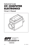
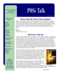
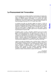
1
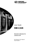
CpE 180
SPRING 2001
CAN BUS DIAGNOSTIC TRANSLATOR
PROPOSAL
TEAM NUMBER 19
BUDGET TOTAL
$179
NAMES OF GROUP MEMBERS
KENNETH HECK
JOHN MURPHY
FACULTY MONITOR
PROFESSOR WILS L. COOLEY
SPONSORS
PROFESSOR ROY S. NUTTER
PROFESSOR G. MICHAEL PALMER
04/06/2001
Contact Person:
Kenneth A. Heck
Route 2 Box 182
Fairmont, WV 26554
(304) 363-6824; (304) 363-2814
[email protected]
TABLE OF CONTENTS
TABLE OF CONTENTS............................................................................................. 2
SECTION 1. INTRODUCTION .................................................................................. 3
SECTION 2. DESIGN OBJECTIVES ......................................................................... 5
2.1 Design Goals and Constraints...................................................................................................... 5
2.2 Design Specifications.................................................................................................................. 6
2.3 Deliverables................................................................................................................................ 9
2.4 Validation................................................................................................................................... 9
SECTION 3. SYSTEM DESCRIPTION .................................................................... 11
3.1 System Description ................................................................................................................... 11
3.2 Block Diagram.......................................................................................................................... 12
3.3 Data Flow Diagrams ................................................................................................................. 13
SECTION 4. ORGANIZATION AND PLANNING .................................................. 16
4.1 Scheduling................................................................................................................................ 16
4.2 Division of Responsibility ......................................................................................................... 17
SECTION 5. BUDGET.............................................................................................. 18
5.1 Budget ...................................................................................................................................... 18
5.2 Budget Justifications ................................................................................................................ 19
SECTION 6. QUALIFICATIONS ............................................................................. 20
6.1 Kenneth Alan Heck, MS ........................................................................................................... 20
6.2 John Murphy............................................................................................................................. 22
SECTION 7. REFERENCES ..................................................................................... 23
7.1 Standards.................................................................................................................................. 23
7.2 Websites ................................................................................................................................... 23
SECTION 8. APPENDICES...................................................................................... 24
8.1 Reliability Estimate................................................................................................................... 24
8.2 Failure Modes and Effects Analysis........................................................................................... 24
8.3 Supporting Information ............................................................................................................. 24
Team 19: CAN Bus Translator : Proposal : Introduction Page 3
SECTION 1. INTRODUCTION
Throughout the 1970's and 80's, the electrical systems in automobiles dramatically
increased in complexity and weight with the continuing addition of electrical devices,
such as sound systems and on-board computers, and with the increasing use of electrical
systems for the control of systems that were previously purely mechanical, such as the
brakes. These devices and systems required correspondingly sophisticated control and
communications systems, especially as their role in the operation of the car became more
central. These developments meant difficulty in the design and maintenance of new
automobiles, and often meant that people could no longer repair their own cars. The
devices themselves and particularly the wiring connecting them became heavy and
complicated, and the opportunities for malfunction increased.
In an effort to simplify the design and maintenance of new automobiles, Robert
Bosch invented the Controller Area Network (CAN) standard in the late 1980's. The
problems he faced included the need for safety, the high noise environment of a running
automobile, and the need for flexibility and speed of high-fidelity communication among
electrical devices in a car. His solution was a high speed bus (Referred to as the CAN
bus), the signals on which traveled on a pair of polarity-switching lines, and which was
capable of extremely reliable performance.
Adoption of the CAN standard by automobile manufacturers came eventually, but
the technology found enthusiastic support in other and varied settings, including the
fields of industrial automation and medical equipment. Each field that adopted the CAN
standard did so with its own small changes and refinements, to the degree that today
some implementations have little in common.
Team 19: CAN Bus Translator : Proposal : Introduction Page 4
The Formula Lightning team at West Virginia University is one such user of the
CAN standard. Led by Dr. Roy Nutter, the Formula Lightning team has devoted itself to
the design of a fully electric race car. His team has found that in order to continue their
work, it is necessary to have a device which will permit them access to the CAN bus of
their car.
Team 19: CAN Bus Translator : Proposal : Design Objectives Page 5
SECTION 2. DESIGN OBJECTIVES
2.1 Design Goals and Constraints
In order to race a car, everything about that car needs to be in optimal condition.
This requires that all the component parts work together well and fluidly without risk of
failure. In order to achieve this goal, all the parts of a car must be extensively tested, and
all the systems examined. This can be done in the workshop, but often the best
measurements and observations are made in the field -- literally, while racing the car
around a track.
The Formula Lightning race car uses a CAN bus for the control and operation of
its electrical systems. In order to ensure the correct and optimal operation of these
electrical systems, a means of accessing the bus must be devised. Access to the bus must
be had under both workshop and field conditions in order to be of use.
Since the CAN bus carries all the communications and control signals of various
devices, it is necessary to be able to read all of those signals in a timely fashion in order
to interpret them. The ability to respond to or elicit these signals is also desirable, since
many devices require interaction in the form of signals on this bus.
A device must be built, therefore, to perform this task of communication and
control. It must also perform the task of translation from CAN signal to a standard signal
that can be read by a technician with a laptop computer running software written by Andy
Pertl. This device must enable the technician to read the signals on the bus, whether all
the signals or only a selected set, and to write signals to the bus.
While this alone is sufficient for workshop use, the nature of the application
requires field testing as described above, and so further constraints are placed on the
Team 19: CAN Bus Translator : Proposal : Design Objectives Page 6
operation of the device. Due to the economy of space in the Formula Lightning car, the
device must operate without a technician or the technician's computer present when the
car is in motion. The device must itself, therefore, be of compact size. Due to the
occasionally extreme weather conditions of the track, and the conditions present in the
interior of a moving race car, the device must be of exceptional durability in order to be
of use for any reasonable length of time.
2.2 Design Specifications
*According to the notes, this should "never be written in 'essay' format", but I'm not sure
how to do it?*
In order to be of use for the Formula Lightning project, the device as described above
needs to communicate according to the SAE standard described in J1939. It will thus be
able to correctly read a signal from a CAN bus line. The signals it must read and write to
the bus may be either or both CAN 2.0A and CAN 2.0B, which are similar packet
structures differing mainly in length. In order to communicate to the laptop computer, the
device must also communicate using the RS-232 standard, using the protocols as defined
by Andy Pertl for his software package.
The act of writing a signal to the bus requires that the device read the signal from the
laptop, and package it correctly for CAN 2.0A or CAN 2.0B. Once correctly packaged,
the device must write the signal to the bus according to the arbitration methods defined in
the CAN standard. The signal that the device writes may also be stored in such a way that
it can be "played back" onto the bus at a predetermined time, or multiple times after
Team 19: CAN Bus Translator : Proposal : Design Objectives Page 7
predetermined intervals. In order to do this, the device must be able to accept and process
instructions regarding its own behavior, and be able to distinguish such instructions from
signals that must be written to the bus.
In order to read from the bus, the device must take a signal in its entirety from the bus
line, and after determining whether the signal is wanted by the user of the device, relay it
to that user. If the user has connected a laptop computer, then the device must
communicate the signal via the RS-232 connection described above. If a laptop computer
is not connected, the device must store the signals in such a way that they can be
retrieved later.
Team 19: CAN Bus Translator : Proposal : Design Objectives Page 8
Input Impedance:
CAN-side: ................................................... 120Ω +/- 12Ω
Device Power Requirements:
Power Sources:............................................ External: 12V,supplied by
shielded cable
Current Draw:.............................................. <200mA
Communications:
CAN-side: ................................................... Max 1Mbit/sec
PC-side:....................................................... Max 115.2Kbit/sec
Communications Protocols:
CAN-side .................................................... (1) CAN 1.x
(2) CAN 2.0A
(3) CAN 2.0B (Read Only)
PC-side........................................................ RS-232
Connections:
CAN-side .................................................... DB-9
CAN-side connector harness........................ (1) DB-9 to 5-pole
(2) DB-9 to 6-pole
(3) DB-9 to 9-pole
PC-side........................................................ DB-9
PC-side connector harness ........................... (1) DB-9 to DB-9
(2) DB-9 to DB-25
Power .......................................................... 2.1mm barrel
Operational Environment:
Electrical Isolation....................................... Max 24V applied to outside
of case
Shock (Force) .............................................. Max 4g
Pressure....................................................... Max 60psi
Water Resistance ......................................... 1ft submersible (or equivalent)
Dimensions (excluding external cabling):
Case............................................................. 2.00” H x 5.00” W x 6.00” D
(51mm H x 127mm W x 153mm D)
Weight......................................................... 3.0 lbs (1.37 kg)
PC Requirements:
Must run CAN software written by Andy Pertl
Team 19: CAN Bus Translator : Proposal : Design Objectives Page 9
2.3 Deliverables
The device, when finished, will consist of a box as described above -- no larger
than 2"x5"x6", weighing not more than 1.37 kilograms, with four openings. The first
opening will allow a cable to connect the device to the CAN bus via DB-9. The second
opening will be a DB-9 type socket for a cable connecting to a computer. This second
opening will be pluggable to prevent entry of dirt, oil or water. The third opening will
allow a power cord. The last opening will permit a flash memory card. This opening will
also be sealable.
The power cord and CAN bus cable will be provided with the device. The user
must provide the cable connecting to the DB-9 socket. One flash memory card will be
provided with the system. Additional cards of the same type may be used by the user, but
purchase, storage, and care of these cards is solely the responsibility of that user.
2.4 Validation
In order to determine that the device works correctly, the following tests will be
performed:
The delivered device will be connected to a laptop computer and a working CAN
bus. This same bus will have on it a similar device (of outside manufacture) for testing
purposes. First, the system will be run so that the bus will carry signals from multiple
sources. The device being tested will identify all of these signals and relay them. The
signals relayed by the delivered device will be compared to those relays by the outside
device to ensure that all signals have been received, and no extraneous signals reported.
Team 19: CAN Bus Translator : Proposal : Design Objectives Page 10
The delivered device will then be instructed to send certain signals over the bus.
The outside device will be consulted to verify that these signals have been sent correctly.
The delivered device will be given instructions by the computer to store all signals from a
given source on the bus (Identified using a CAN numeric identifier) and then attached to
a CAN bus without the computer attached. The system will be run so that the bus carries
signals from this source for two minutes, then shut down, and the delivered device
attached to a computer to relay the stored data.
Lastly, the device will be dropped onto the ground from a height of three feet,
sprayed with water, and then subjected to all of the above tests once more.
Team 19: CAN Bus Translator : Proposal : System Description Page 11
SECTION 3. SYSTEM DESCRIPTION
3.1 System Description
The device will be a single-board electronic device with a 12-volt DC power
supply (external). It will contain a 20MHz oscillator as the clock, the DB-9 connectors
necessary for interfacting the PC and the CAN bus, and a connector for the flash memory
card. The PC's DB-9 connector will be electrically isolated from the rest of the device
using opto-isolators.
PIC chips will handle the tasks of interfacing with the CAN bus, interfacing with
the computer (via RS-232), storing information to the flash memory, receiving and
executing instructions from the computer, and both determining then communicating
error states.
Team 19: CAN Bus Translator : Proposal : System Description Page 12
3.2 Block Diagram
Team 19: CAN Bus Translator : Proposal : System Description Page 13
3.3 Data Flow Diagrams
CAN Bus
CAN
Signal
CAN
Signal
Translate
CAN to RS-232
Translate
RS-232 to CAN
RS-232 Signal
PC via RS-232
Level 0 DFD
RS-232 Signal
Team 19: CAN Bus Translator : Proposal : System Description Page 14
CAN Bus
CAN Signal
CAN Signal
Convert signal
to TTL
TTL to CANReady signal
Raw TTL Signal
Buffer 1
TTL Signal
Raw TTL Signal
Package TTL as
RS-232
Remove RS-232
and form TTL
Packet
RS-232 Signal
Buffer 2
RS-232 Signal
RS-232 Signal
Send RS-232 to
PC
Send RS-232 to
CAN
RS-232 Signal
RS-232 Signal
PC via RS232
Level 1 DFD
Team 19: CAN Bus Translator : Proposal : System Description Page 15
Raw TTL Signal
Buffer 1
Raw TTL Signal
Error-check signal
Error Signal
Valid Signal
Generate status
and error signal
Generate data
packet
Partial RS-232
Error Packet
Partial RS-232
Data Packet
Package RS-232
packet with proper
parity
Complete RS-232 Packet
With Parity
Buffer 2
Complete RS-232 Packet
With Parity
Level 2 DFD
Team 19: CAN Bus Translator : Proposal : Organization and Planning Page 16
SECTION 4. ORGANIZATION AND PLANNING
4.1 Scheduling
(OK, this is just a list of things we'll need to do)
buy parts
build case
lay out and build circuit
program PICs
learn how to use flash memory cards
learn how to use Pertl's program (And make any changes needed to access our additional
functionality)
write instruction calls
write user manual
test
parts should be bought soon, and all the "learn" stuff, too. How are we going to deal with
the summer in all this?
Do we include it in our plans, or just pretend we're not doing anything over the summer?
1
20
20
20
10
20
10
0
5
0
5
10
3
5
119
2) Learn to use and wire CANBus PIC
7) Program the CANBus PIC
3) Learn to use and wire PIC#2
8) Program PIC#2
6) Learn to use and wire memory card
4) Learn to use Andy Pertl’s software
5) Make changes to AP software
9) Design power supply
10) Learn to use and wire the serial port
11) Learn to etch boards
12) Learn to build/etch prototype board
13) Build case to meet specifications
14) Test project to ensure specifications
TOTAL
KAH
119
5
3
10
5
5
0
40
10
10
0
5
0
5
1
JM
Effort
1) Buy Parts
Task
08/
20
08/
27
09/
03
09/
10
09/
17
09/
24
10/
01
10/
08
10/
15
Week Beginning
10/
22
10/
29
11/
05
11/
12
11/
19
11/
26
Team 19: CAN Bus Translator : Proposal : Organization and Planning Page 17
4.2 Division of Responsibility
Team 19: CAN Bus Translator : Proposal : Budget Page 18
SECTION 5. BUDGET
5.1 Budget
Project Cost
Proposal Cost
1. CANBUS PIC – MCP2510
$7
$7
2. Additional PIC for other Functions
$10
$10
3. PICStart Plus Programmer
$150
$0
4. MAX232A
$5
$0
5. DB9 connector (Receptacle)
$3
$3
6. DB9 connector (Plug)
$3
$3
7. Circuit Board Etch Kit
$30
$30
8. Capacitors, Resistors, Inductors
$5
$5
9. Case (Aluminum)
$15
$15
10. Power Connector (Receptacle)
$1
$1
11. Power Connector (Plug)
$4
$4
12. Oscillator
$3
$3
13. IC Sockets
$1
$1
14. Compact Flash Memory (32MB)
$45
$45
15. Compact Flash Socket
$5
$5
16. DC-DC Converter
$9
$9
17. Fuse Holder
$1
$1
18. Power Switch
$2
$2
19. Any other discrete components
$5
$5
20. Miscellaneous (solder, etc.)
$5
$5
21. Shipping/Handling Charges
$20
$20
TOTAL
$334
$179
Requested from Sponsors=$79
Requested from CSEE Department=$100
____________________________
Sponsor Signature
Date
____________________________
Chair Signature
Date
____________________________
Monitor Signature
Date
Team 19: CAN Bus Translator : Proposal : Budget Page 19
5.2 Budget Justifications
1. CANBUS PIC – MCP2510
Digi-Key
2. Additional PIC for other Functions
Digi-Key
3. PICStart Plus Programmer
Digi-Key
4. MAX232A
Digi-Key
5. DB9 connector (Receptacle)
Newark
6. DB9 connector (Plug)
Newark
7. Circuit Board Etch Kit
Newark
8. Case (Aluminum)
Newark
9.
Newark
Power Connector (Receptacle)
10. Power Connector (Plug)
Newark
11. Oscillator
Newark
12. Compact Flash Memory (32MB)
Buy.com
13. Compact Flash Socket
Newark
14. DC-DC Converter
Newark
15. Fuse Holder
Newark
16. Power Switch
Newark
Team 19: CAN Bus Translator : Proposal : Qualifications Page 20
SECTION 6. QUALIFICATIONS
6.1 Kenneth Alan Heck, MS
Kenneth Alan Heck, MS
Route 2 Box 182
Fairmont, WV 26554
Home Phone : (304) 363-6824
E-Mail: [email protected]
Education :
01/98-Present:
University :
Coursework :
West Virginia University, Morgantown, WV
Pursuing BS in Computer and Electrical Engineering
08/96-12/96 :
College :
Registration :
License :
Santa Fe Community College, Gainesville, FL : EMT - B, December 1996
National Registry of Emergency Medical Technicians - #B1103946
West Virginia - #B-036323
08/92-02/96 :
University :
Thesis :
Research Director :
Graduate Coursework :
Equipment Skills :
Other Duties :
08/88-05/92 :
University :
Coursework :
Special Topics Course :
Equipment Skills :
Honors/Scholarships :
University of Florida, Gainesville, FL : MS, December 1995
"General Synthetic Methods for Alpha-hydroxy Ketones"
Dr. Alan R. Katritzky, Kenan Professor, Center for Heterocyclic Compounds
1 sem. each : General Organic, Organic Synthesis, Organic Mechanism,
Organic Spectroscopy, Inorganic, Organometallics, Quantum Theory
300MHz NMR's : Varian Gemini-300, VXR 300, GE QE-300; HPLC
Katritzky group lab steward, miscellaneous equipment repair
West Virginia University, Morgantown, WV : BA, Chemistry December 1992
Mostly BS and Honors courses, organic courses with microscale techniques
X-Ray diffraction
IR : Perkin-Elmer; PC-based systems
(i) WVU Presidential Scholarship
(ii) John A. Moore (Chemistry) Scholarship
(iii) WVU Honors Program
Experience :
01/00-Present :
Business :
Title :
Functions:
08/97-12/99 :
Employer :
Title :
Supervisor :
Duties :
Heck Solutions
Owner
Software Development specializing in Access 97
Custom-built PC’s/Upgrades
PC Diagnosis/Repair
West Virginia University, Financial Aid Office, Morgantown, WV 26506-6004
Information Systems Technician
Tresa Weimer, Supervisor : (304) 293-8571 ; 1-800-344-WVUl
System Administrator of Local Area Network running Novell Netware 4.11
Training employees to use software : Netware 4.11, Win 95, Win 98,
WP6.1, FoxPro 2.6, BANNER 2.15, MS Office Pro 97
Maintenance and Repair: Various PC’s and Printers
Developing need-specific software for varying uses in the office :
Access 97 , FoxPro 2.6
Supervision of Work Study employees
Team 19: CAN Bus Translator : Proposal : Qualifications Page 21
06/97-Present :
Employer :
Title :
Supervisor :
Duties :
06/96-02/97 :
Employer :
Title :
Supervisor :
Duties :
01/93-02/96 :
Employer :
Title :
Supervisor :
Duties :
08/88-07/92 :
Employer :
Title :
Supervisor :
Duties :
03/91-07/92 :
Employer :
Title :
Supervisor :
Duties :
Monongalia General Hospital, 1200 JD Anderson Drive,
Morgantown, WV 26505
Part-Time Monitor Tech
Glenda Broad: (304) 598-1506
Watching 5 monitors capable of 8 strips each, paging nurses for dysrhythmias
Recording and analyzing rhythm strips once per shift
Tracking patient room assignments, notifying necessary personnel for
admits/discharges
Maintaining patient information board for physicians, nurses, administrative
personnel
Farchan Laboratories, 4906 NW 53rd Street, Gainesville, FL 32653
Bench Chemist - Research and Development
Dr. Radi Awartani : (352) 374-6825
Running small (50mL) to large (22L) scale reactions as directed
Supervising technicians in running reactions
Quality control analysis by GC, HPLC, IR, Karl-Fischer water analysis,
titration, melting point and refractive index
Lab equipment maintenance
University of Florida, Department of Chemistry, Gainesville, FL 32611
Graduate Research/Teaching Assistant
Prof. Merle A. Battiste : (352) 392-0552
3 sem. General Chemistry, 2 sem. Organic Chemistry Lab
West Virginia University, Financial Aid Office, Morgantown, WV 26506-6004
Clerical Assistant
Brenda Thompson, Director : (304) 293-5242 ; 1-800-344-WVUl
Clerical work : Filing, typing, answering phones, stocking, errands
Developing need-specific software for varying uses in the office :
FoxPro 2.0 LAN
Training employees to use software : Netware 2.10, WP5.1, FoxPro 2.0, DOS
PC Maintenance
First National Bank of Morgantown, 201 High Street, Morgantown, WV 26505
(now Huntington Banks, WV)
Part-Time Computer Operator
Scot Epling, Assistant Vice President : (304) 367-2452 ; 1-800-377-BANK
Unsupervised after hours final sorting of personal checks using a
Honeywell DPS 6
Developing need-specific software : dBase IV 1.1 and QuickBasic
Software installation : WP5.1, Lotus, PCTools
Diagnosing and correcting PC hardware problems
Publication :
A. R. Katritzky, K. A. Heck, J. Li, A. Wells, C. Garot, "1-(1-Alkenyl)benzotriazoles: Novel
Equivalents for the Synthesis of α-Hydroxy Ketones", Synth. Commun., 26(14), 2657-2670.
(1996)
Team 19: CAN Bus Translator : Proposal : Qualifications Page 22
6.2 John Murphy
John Murphy
910 Montrose Ave
Morgantown, WV
26505
(304)292-8870
[email protected]
Resume
Objectives:
To obtain a graduate degree in electrical engineering in the particular field of robotics.
To gain experience designing, building, controlling, and maintaining robotic systems.
Job Experience:
Intern, NASA IV&V
Summer, 1996
Fairmont, WV (Funded by George Washington University)
Involved with SORT (Software Optimization and Reuse Technology) project, a software
engineering effort as related in particular to Marshall Space Flight Center's flight furnace
project.
Oral demonstrations of progress given both to peers and superiors at the end of the internship
Math tutor, West Virgina University Math Department
Morgantown, WV
Aug 2000 - present
Education:
West Virginia University
1997-present
Morgantown, WV
(Expected graduation date: Dec 2001)
Degrees to be received:
BSCpE, BSEE, emphasis in control systems
Kansai Gaikokugo Daigaku (Kansai Foreign Language University) Fall 1999
Hirakata-Shi, Osaka, Japan
Morgantown High School
Morgantown, WV
1994-1997
Skills:
Programming (Windows, MS-DOS and UNIX environments):
C, Java, Intel x86 assembly, PIC assembly, PIC C, Ada, Matlab, Perl, Lisp
Spoken and Written Japanese
Use of fuzzy logic and genetic algorithm techniques, particularly in control applications
Experience designing with and programming for PIC chips
Team 19: CAN Bus Translator : Proposal : References Page 23
SECTION 7. REFERENCES
7.1 Standards
1) SAE J1939
7.2 Publications
1) Design with PIC Microcontrollers, Peatman, John B., Prentice Hall, New Jersey, 1998.
7.3 Websites
1) AnyBus Official Site : http://www.hms.se/
2) CAN in Automation : http://www.can-cia.de/
3) Dearborn Group, Inc. : http://www.dgtech.com/products/dpa.phtml
4) DeviceNet-ODVA Official Website : http://www.odva.org/10_2/00_fp_home.htm
5) International Organization for Standardization homepage : http://www.iso.ch/
6) KVASER Controller Area Network pages : http://www.kvaser.com/can/index.htm
7) OSEK/VDX : http://www.osek-vdx.org/
8) Triangle Data : http://www.triangledigital.com/products/productscanbus.htm
9) Wesley Tang's Can Links : http://www.warwick.ac.uk/~esrpy/links.htm
10) Zanthic Products : http://www.zanthic.com/can4usbm.htm
Team 19: CAN Bus Translator : Proposal : Appendices Page 24
SECTION 8. APPENDICES
8.1 Reliability Estimate
8.2 Failure Modes and Effects Analysis
8.3 Supporting Information