1
HEIDENHAIN
DR.JOHANNES HEIDENHAN GmbH
D-8225 Traunreut ‘Tel. (08669) 31-D
Kundendienst
..~
Service
Subject
to change (without
Manual
TNC~~lSl
notice)
DR. JOHANNES HEIDENHAIN GmbH is constantly
working on further
developments
of its TNC Controls.
It is therefore
possible
that details
of your Control may differ
slightly
from those
described herein.
If that is the case please order a suitably
revised
issue of the Service Manual.
Copying/Duplication
This manual is provided
subject to the condition
that no part
of it shall be reproduced in any form or by any means without
our prior consent in writing.
Issue:
01/87
lleIuelullnll\
DR. JDHANNES HEIDENHAJN GmbH
D-8225 Traunreut ‘Tel. (08669) 31-O
SERVICE
Page
Kundendienst
contents
1.
Use nf
-1 tllc
-l
2.
2.1
2.2
2.2.1
2.2.2
2.2.3
2.2.4
2.2.5
2.2.6
Fault
Diagnosis
for fault-finding
Flow diagrams
for fault
location
Fault
diagnosis
for the complete
installation
Use of the integrated
supervision
system
Testing
of the VDU and associated
circuitry
Testing
of the mains supply
and the Power Supply
Testing
of the measuring
systems
and wiring
3.
3.1
3.1.1
3.1.2
3.1.3
3.2
3.3
3.4
Exchange
Information
Exchanoina
Control
units
Procedure
for exchanging
the TNC 151 A/E Control
Procedure
for exchanging
the TNC 151 P/V Control
Procedure
for exchanging
the PIG I/O Board of the
Board Exchange
Software
Exchange
ReDlacement
Parts,
Loan/Exchange/Service
Units
4.
4.1
4.2
4.3
4.4
Additional
Information
Block Diagram
Description
Block
Diagram
TNC 151
Wiring
Diagrams
Machine
Parameters
Service
Manual
2
^
"
"
"
"
"
n
"
"
n
"
"
"
nn
3
4
4
5
14
15
17
18
..
procedure
Burn-In
Page
..
Unit
Test
PL 100 B/110
B
.l
'1
"
36
37
37
38
39
40
45
48
"
X8
n
"
"
50
50
55
70
75
1
MANUAL TNC 151
neluelunnllu
DR. JOHANNES HEIDENHAIN GmbH
D-8225 Traunreut .Tel. (08669) 31-O
1. Use of the Service Manual TNC 151
In order to determine the fault condition
on an NC machine,
a fundamental knowledge of the machine and the drives is
necessary, as well a a knowledge of their interaction
with
the Control and measuring system. In addition,
improper use
such as incorrect
NC programming or incorrect
of the Control,
selection
of machine parameters can lead to the occurrence
Further information
in this
respect can
of fault conditions.
be found in:
.TNC 151 OPERATING MANUAL
.TNC 151 MOUNTING INSTRUCTIONS AND INTERFACE CIRCUIT CONTROLMACHINE
.TNC 151 PLC-DESCRIPTION
SERVICE MANUAL TNC 151
Page 2
Section 1
The TNC 151 Service Manual is used for the diagnosis,
localisation
and remedying of faults on TNC controlled
machines.
In chapter 2, Fault Diagnosis,
a set of flowcharts
enables
the user to pinpoint
the source of a fault from its symptoms _
An integrated
built-in
supervision
system and a Burn-In
Test Program specifically
developed for testing the Control
can aid in the location
of faults.
Important
guidance for the exchange of entire Controls,
individual
boards, or software is given in section 3,
Exchange Information.
Section 4, Additional
Information,
contains a block diagram of the Control,
a wiring diagram for each version of
the Control,
and a list of machine parameters with permissible entry values.
HEIDENHAIN
SERVICE
Page 3
Section
DR. JOHANNES HElDENHAlN GmbH
D-8225 Traunreut .Tel. (08669) 31-O
Kundendienst
2.
Fault
2.1
procedure
Diagnosis
for
fault-finding
To locate
and rectify
a fault
that
has arisen
in a TNC installation,
it is of foremost
importance
to analyse
the behaviour
of the system
as a whole:
that
is,
the TNC Control,
the machine-tool
and the measuring
system.
in flow
diagram
form,
the procedure
for
exam2.2.1
shows,
ining
the complete
installation.
In addition,
the HEIDENHAIN
TNC 151 Contouring
Control
includes
an extensive
integrated
supervision
system
for the
avoidance
of entry/operator
faults
and for the recognition
and diagnosis
of technical
defects
in the installation
(see section
2.2.2)
The Burn-In
Test
Program
can be used as further
fault
localizing
and in the dynamic
testing
of
hardware
(see section
2.2.6).
support
in
the Control's
MANUAL
2/2.1
TNC 153
SERVICE
Page 4
Section
Kundendienst
2.2
Flow
diagrams
2.2.1
Fault
diagnosis
(Control/Measuring
for
fault
for
location
the complete
installation
System/Machine-tool)
MANUAL
2.2/2.2.1
TNC 151
neluelunnllu
DR. JOHANNES
D-8225Traunreut
2.2.2
Use
of
the
HElDENHAlN
.Tel. (08669)
integrated
GmbH
SERVICE
Page 5
Section
31-O
supervision
system
The TNC 151 incorporates
an extensive
integrated
supervision
system
for
the avoidance
of operator-errors
and the detection
and diagnosis
of technical
faults
in the TNC installation
(ie the installation
comprising
the TNC, the machine-tool
and the measuring
system).
The supervision
system
is made up
and software
within
the TNC, and
the TNC is switched
on. If a fault
a message
operator-error
occurs,
cating
(in abbreviated
form)
the
of a mixture
of hardware
operates
continuously
whilst
is detected,
or if an
will
be displayed,
indinature
of the problem.
Flashing
ASIS
fault
X/Y/Z/4
messages
MEAS.
EMERGENCY
Example
of fault
GROSS POSITIONING
on machine-tool:
ERROR A
SYSTEM DEFECTIVE
STOP PLC
TNC OPERATING
ERROR A/B/C/D
TEMP.
EXCEEDED
ERROR IN PLC PROGRAM A...Q
TNC ELECTRONICS
fault
with
measuring
SYSTEM DEFECTIVE
TNC 151
POINT
GROSS POSITIONING
example
of
X-MEASURING
2.2.2
STOP DEFECTIVE
WRONG REFERENCE
Example
of fault
with
TNC internal
electronics:
a) TNC OPERATING TEMP. EXCEEDED
b) EXCHANGE BUFFER BATTERY
c) TNC ELECTRONICS
DEFECTIVE
O...3/A...K
TNC 151
The system
distinguishes
between
what are considered
to be
harmless
errors
and serious
faults,
in that
faults
are shown
as flashing
displays.
Examples
of faults
are measuring
system
faults,
drive
faults
and faults
in the TNC's
internal
electronics.
The occurrence
of a fault
leads
to the machine
being
switched
off
via the emergency-stop
contactor.
The fault
must
then be rectified
before
the TNC is switched
on again.
EMERGENCY
Example
of operator-error:
a) KEY NON-FUNCTIONAL
b) ENTRY VALUE INCORRECT
MANUAL
DEFECTIVE
O...3/A...K
system:
CHECK SUM ERROR XXOO...XXFF
The significance
pages 8 to 13
A (non-flashing)
@key
on the
A list
of error
of
these
fault
messages
is
explained
on
error
message
can be cleared
by pressing
the
which
normal
operation
may resume.
TNC, after
messages
is given
on page 7.
HEIDENHAIN
SERVICE
Page 6
Section
DR. JOHANNES HEIDENHAN GmbH
D-8225 Traunreut.Tel.(08669)31-0
Error
message
"MCBA?JGB
MANUAL TNC 151
2.2.2
BUFFER
BATTBRY"
Particular
mention
should
also
be made about
the implications
of the instruction
to exchange
the buffer
battery:
If the dialogue
display
indicates
"EXCHANGE BUFFER BATTERY",
new batteries
must be inserted
within
one week.
The buffer
battery
compartment
is located
behind
the screw
cover
in the lower
left-hand
corner
of the operating
panel.
When exchanging
the batteries,
special
care
should
be taken
that
the polarity
is correct
(POS-pole
of battery
outwards).
The battery
needs to have IEC designation
"LR 6" and must be
of the leak-proof
type.
We especially
recommend
the use of
VARTA Alkaline
batteries
type
"4006".
With
discharged
(or
missing)
buffer
batteries,
the memory for the machine
parameters
and for the user-program
will
be supported
only
as long
as the mains
remains
switched
on. Continued
operation
is still
possible
but the memory contents
will
become erased
in the
event
of a mains
failure.
Please
note that
the TNC has to be
switched
on when exchanging
the buffer
batteries.
If a mains
failure
occurs
during
a battery.chanqe
(or when the battery
is
discharged
or missing),
the re-entry
of the machine
parameters
and the user-program
will
be necessary.
Use
of
the
integrated
supervision
system.
HEIDENHAIN
SERVICE
Page 7
Section
DR. JOHANNES HEIDENHAIN GmbH
D-8225 Traunreut
Tel. (08669) 31-O
MANUAL TNC 151
2.2.2
Kundendienst
Error
The
(i)
(ii)
messaqes
TNC 151
meanings
of many of these
error
messages
are
Operating
Manual
TNC 155 A/TNC 155 P
Mounting
Instructions
and Interface
Circuit
FEY NON-FUNCTIONAL
PROGRAM MEMORY EXCEEDED
SEARCH ADDRESS MISSING
TOOL DEF 0 NOT PERMI'M'ED
PROGRAM NUMBER ON TAPE ALLOCATED
JUMP TO LABEL 0 NOT PERMITTED
ENTRY VALUF INCORRECT
CC-BLOCK
MISSING
CIRCLE
END POS. INCORRECT
TOOL DEF MISSING
TOOL CALL MISSING
LABEL NUMBER NGT ALLOCATED
EXCESSIVE
SUPROGRAMMING
ANGLE REFERENCE MISSING
PLANE WRONGLY DEFINED
TOOLRADIUS
TOOLARGE
ROUNDING RADIUS TOO LARGE
PATH OFFSET WRONGLY STARTED
PATH OFFSET WRONGLY ENDED
ROUNDING-OFF
UNDFINBD
ROUNDING-OFF
NOT PERMITTED
AXIS DOUBLE PROGRAMMED
WRONG RPM
NO EDITING
OF RUNNING PGM
RADIUS COMP. UNDEFINED
LIMIT
SWITCH X+
LIMIT
SWITCH XLIMIT
SWITCH Y+
LIMIT
SWITCH Y-
explained
in:
Control-Machine
TNC 151 A/TNC
LIMIT
SWITCH AXIS Z+
LIMIT
SWITCH AXIS ZLIMIT
SWITCH AXIS
4+
LIMIT
SWITCH AXIS 4EXCHANGE BUFFER BATTERY
TRANSFERRED DATA INCORRECT
ME: CASSETTE MISSING
ME: CASSETTE LOCKED
NE: WRONG MODE SELECTED
NE: WRONG PROGRAM DATA
MB: CASSETTE EMPTY
ME: PROGRAM INCOMPLETE
ME: TAPE END
WRONG PROGRAM DATA
MACHINE PARAMETER INCOMPLETE
EXT. IN-/OUTPUT
NOT READY
MIRROR IMAGE ON TOOL AXIS
WRONG AXIS PRCGRANMED
NRONG SIGN PRCGRANMED
SPINDEL ROTATES MISSING
SLOT WIDTH TOO LARGE
CYCLE INCOMPLETE
SELECTED BLOCK NOT ADDRESSED
PROGRAM START UNDEFINED
POSITIONING
ERROR
EMERGENCY STOP
ARITHMETICAL
ERROR
OPERATION PARAMETERS ERASED
3D-INTERPOLATION
NOT PERMITTED
151 P
FURTHER PROGRAM ENTRY IMPOSSIBLE
PROGRAM NUMBER UNAVAILABLE
PROGRAM NUMBER ALLOCATED
LABEL NUMBER ALLOCATED
TOOL NUMBER ALLOCATED
RELAY EXT. DC VOLTAGE MISSING
POWER INTERRUPTED
PGM XXXXXXXX UNAVAILABLE
TWO TOOL DEF XXX WITH PGM CALL
CIRCLE CENTRE UNDEFINED
XXXX
ADDRESS LETTER ALREADY ASSIGNED
BLOCK TOO LONG
G-CODE GROUP ALREADY ALLOCATED
ILLEGAL
G-CODE
BLOCK NUMBER ALREADY ALLOCATED
BLOCK FORMAT INCORRECT
N-CODE MISSING
BLK FORM DEFINITION
INCORRECT
PGM-SECTION
CANNOT BE SHOWN
TOO MANY USER PARAMETERS
PROTECTED PGM
ILLEGAL
NC-BLOCK
CHAMFER NOT ALLOWED
HEIDENHAIN
SERVICE MANUAL TNC 151
Page 8
Section 2.2.2
DR. JOHANNES HEIDENHAN GmbH
D-8225 Traunreut ‘Tel. (08669) 31-O
Kundendienst
Fault
descriptions
WJU Display
THC 151
(flashing)
X-MEASURING
Y-MEASURING
Z-MEASURING
AXIS 4 MEAS.
SYSTEMDEFECTIVE
SYSTEM DEFECTIVE
SYSTEMDEFECTIVE
SYSTEM DEFECTIVE
EMERGENCYSTOP DEFECTIVE
WRONGREFERENCEPOINT
Fault
cause
Possible
fault
location
.Measurinq system not connected
.C&le damaged
.Glass scale dirty or damaged
.Scanninq head damaged
.Measurinq system supervision
damaged
Measuring
.Fault in the emergency stop
circuit
of the machine (for checking
routine
see Mounting Instructions
and
Interface
Circuit
Control-Machine
manual TNC 151 A/TNC 151 P)
.Defect in Control's
internal
Emergency
Stop supervision
Analoque Board
PLC I/O Board
PIG Interface
Board
SE Board
Teminal
Board
.Traversed-over
reference
point lies
outside of the reference
point end
position
(also see Mounting Instructions and Interface
Circuit
Control
Machine
TNC 151 A/TNC 151 P.
.Defect in Control/machine
interface
Machine (cams/switches
"reference
end-position"
pulse inhibit")
Analoque
system
Board
PLC I/O Board
PLnCInterface
Board
SE Board
Terminal Board
151 P)
(TNC 151 P)
(TMC 151 A)
PIN2 151 A)
(TNC
or "reference
(TNC 151
(TNC 151
(TNC 151
VTNC 151
P)
P)
A)
A)
HEIDENHAIN
DR. JOHANNES
HEIDENHAIN
D-8225 Traunreut'Tel.(08669)
VDU Display
GROSS POSITIONING
31-O
Pault
(flashing)
EMERGENCY-STOP
SERVICE
Page 9
Section
GmbH
cause
With
standard
PLC program,
faulty
reply
from output
A6 ("Lock
for
spindle
on")
to
input
E20 ("reply:
Lock
for
spindle
on")
Fault
message
EMERGENCY-STOP
PLC
appears
only
when no additional
PLC marker
is set for
the fault
message
PC
ERROR A
.Trailing
error
greater
than value
entered
in MP 174.
(see Mounting
Instructions
and Interface
Circuit
Control-Machine
manual
TNC 151 A/
TNC 151 P)
.Deviation
from the intended
position
at
standstill
greater
than the value
entered
in MP 169
(see Mounting
Instructions
and Interface
Circuit
Control-Machine
manual
TNC 151 A/
TNC 151 P)
-Exceeding
the range
for
the continuous
position
supervision
determined
by MP 57.
(see Mounting
Instructions
and Interface
Circuit
Control-Machine
manual
TNC 151 A/
TNC 151 P)
.Relationship
between
output
voltage
and
traversed
distance
outside
of the defined
tolerance.
.Defect
in the pulse
counting
section
(Control
circuitry)
after
the transducer
signal
supervision
MANUAL TNC 151
2.2.2
Possible
fault
Terminal
board
location
(TNC
151 A)
In the Case of Gross
Positioning
Errors
A/B/C/D
the fault
could
lie
with
any
element
in the closed
loop
servo
system.
ie Control
hardware
(CLP Processor
Bra.),
n
11
(Analogue
Brd.),
servo
II
amplifier
"
(offset
(gain
motor,
tacho,
measuring
system,
external
forces
acting
inappropriate
MP values
voltages),
too low),
on drives,
programned.
Aid:
1. Program
MP 54 (acceleration)
small
as possible.
2. Adjust
rapid
traverse
(as
trailing
error
as possible).
3. Gradually
increase
MP 54.
If this
does not help:
fault
in the Control
hardware
loop)
or in the machine
as
small
(closed
a
HEIDENHAIN
DR. JOHANNES
D-8225Traunreut
SERVICE MANUAL TNC 151
Page 10
Section
2.2.2
HEIDENHAIN GmbH
.Tel. (08669) 31-O
Kundendienst
VDU Display
Fault
(flashing)
GROSS POSITIONING
ERROR B
Possible
cause
.The Control-calculated
tage
(implied
by
than
10 V
trailing
analogue
error)
output
volis greater
see
above
GROSS POSITIONING
ERROR C
.The analogue
output
voltage
actually
necessary
to obtain
a desired
speed deviates
from
the expected,
calculated
voltage,
by more
than the voltage
programmed
in MP 234
see
above
GROSS POSITIONING
ERROR D
.The actual
position
at standstill
deviates
from the intended
position
by more than the
distance
programmed
in MP 169
see
above
.Ambient
temperature
inside
the TNC has exceeded
+65Y
.Fault
in the temperature
supervision
Ambient
TX-OPERATING
TEMP.
ExCEeDED
Analogue
fault
location
temperature
Board
of
Control
HEIDENHAIN
SERVICE MANUAL TNC 151
Page 11
Section
2.2.2
DR JOHANNES HElDENHAlN GmbH
D-8225 Traunreut .Tel. (08669) 31-O
Kundendienst
CRT display
Fault
(flashing)
ERROR IN PLC PROGRAM
....
A
Possible
origin
Fault
with
Description
36 . ...40)
safety-related
marker
manual
TNC 155 A/TNC
fault
(see PLC155 P pages
PLC Program,
Start
Error
Key
with
B
Rapid
traverse
C
Direction
D
Feed
E
Start
PLC positioning
X-axis
F
Start
PLC positioning
Y-axis
G
Start
PLC positioning
Z-axis
H
Start
PIG
I
Direction
key
x+
J
Direction
key
X-
K
Direction
key
Yi
L
Direction
key
Y-
M
Direction
key
z+
N
Direction
key
Z-
0
Direction
key
IV+
P
Direction
key
IV-
Q
Undefined
macro
safety-related
marker
key
latch
key
release
positioning
called-up
IV-axis
via
location
PLC marker
Main
Processor
Board
HEIDENHAIN
SERVICE MANUAL
Page 12
Section
2.2.2
DR JOWNES
HEIDENHAJN GmbH
D-8225 Traunreut .Tel. (08669) 31-O
151
TNC
Kundendienst
VDU Display
TNC-ELECTRONICS
* CRC = Cyclic
** MID = Macro
Fault
(flashing)
DEFECTIVE
Redundancy
Instruction
cause
False
CRC CHECK-SUM*
of machine-related
data excluding machine
parameters.
(Baud rate,
limitation,
preset
etc)
False
CRC CHECK-SUM*
(machine
parameters)
False
CRC CHECK-SUM*
(user
memory)
Integrated
Test Program
execution
incomplete
Software
error
Main Processor
Software
error
CLP Processor
MID interrupt**
CLP Processor
CLP Processor
instruction
stack
overflow
False
instruction:
Main
Processor
-CLP
PrOCessOr
False
instruction
(display
mode):
Main
Processor
--cCLP
Processor
CLP Processor
RAN
Overflow
interrupt
MID interrupt
Main
Processor
Equipped
with
incorrect
language
version
FFFF Main Processor
RAM E&$8...
0
Check
Detection
Possible
Main
fault
location
Processor/Memory
Memory/Main
Processor
Memory/Main
Processor
Main
Processor/Memory
Main
CLP
CLP
CLP
CLP
Board
Board
Board
Board
Processor
Board
Processor
Board
Processor/Main
Processor
Processor
Board
Processor/Main
Processor
CLP-Processor/Main
CLP Processor
Main Processor
Main Processor
Main Processor
Main
Processor
Processor
Board
Board
Board
Board
Board
Board
Board
Board
HEIDENHAIN
DR JOHANNES
D-8225Traunreut
HEIDENHAIN
SERVICE MANUAL TNC 151
Page 13
Section
2.2.2
GmbH
.Tel.(O8669)31-0
Kundendienst
VDU Display
CHECK-SUM
Fault
(flashing)
ERROR
Possible
cause
fault
location
xx00
CRC CHECK-SUM error
with
EPROM 4
XX = correct
CHECK-SUM value
00 = code for
faulty
EPROMs
Main
Processor
Board
xx02
CRC CHECK-SUN
with
EPROM 5
Main
Processor
Board
xx04
with
EPROM 6,7,8
Main
Processor
Board
XXOA
with
EPROM 9
Main
Processor
Board
(PLC program)
XXOB
with
EPROM 9
Main
Processor
Board
(PLC
xxoc
with
EPROM A
Main
Processor
Board
xx10
with
EPROM B,C,D
Memory
Board
xx17
with
EPROM E
Memory
Board
XX18
with
EPROM F
Memory
Board
XXlA
with
EPROM
Memory
Board
XXlC
with
EPROM H,K
Memory
Board
XXlF
with
EPROM K
Memory
Board
xx20
with
EPROM 2
CIZ
error
G
Processor
Board
dialogue)
xx21
CRC CHECK-SUM
CLP Processor
the operating
error
in RAN area on the
Board
in which
a part
of
program
is stored
CLP Processor
Board
xx22
CRC CHECK-SUM
error
CLP Processor
Board
(export
version)
XX23
CRC CHECK-SUM
CLP Processor
ating
program
error
in the RAM area on the
Board where
part
of the operis stored
CLP Processor
Board
(export
version)
XXFF
CRC CHECK-SUM error
PLC Marker
2815 is
with
with
set
EPROM 3
PLC-RAM
Main
Processor
Board
nelueluniillu
DR. JOHANNES
D-8225Traunreut
HEIDENHNN GmbH
.Tel.(O8669)
31-O
Se&ion
Kundendienst
2.2.3
Testing
SERVICE MANUAL TNC 151
Paae 14
of the VDU and associated
2.2.3
circuitry
The first
objective
is to determine whether the fault is
actually
with the Display Unit, in which case it must be
returned to DR JOHANNES HEIDENHAIN for repair,
or whether
it lies elsewhere,
with the asscociated
circuitry,
in
which case repairs may be possible without returning
the
unit.
The Display Units BE 111 and BE 211 are powered by an 11V
dc supply from the Power Supply Board. This is a possible
source of the fault,
in which case the test and repair procedure continues according to section 2.2.4, Testing of the
mains supply end the Power Supply Unit.
If the fault is not due to a detective
power supply, it is
likely
to be due to the CLP Processor Board, which contains
the control
circuitry
for the Display Unit. This can be
verified
by exchanging the board for one when is known to
function
correctly.
If the fault still
persists
then must be due either to bad
connections
within the TNC (eg on the Connector Board), or
to faults on both the VDU end the CLP Processor Board.
See the diagram opposite for a logical
locating
the fault in the system.
procedure
for
Testing
of the VDU and associated
circuitry.
7 HEIDENHAIN
Blllh
SERVICE MANUAL
Page 15
Section
2.2.4
DR. JOHANNES HEIDENHAJN GmbH
D-8225 Traunreut .Tel. (08669) 31-O
TNC 151
Kundendienst
2.2.4
Testing
of
the
mains
supply
and
the
Power
Supply
Unit
The procedure
for testing
the Power
Supply
Unit
is shown in
the flow
diagram
on page 16. As part
of that
procedure,
it
may be necessary
to test
the voltages
at various
points
on
the Power
Supply
Board.
The diagram
below
and the table
opposite
show the locations
of the test
points
(solder
terminals)
on the Power Supply
Board,
and the respective
"nominal"
and "actual"
test
voltages
under
load.
.
6
7
9,10,1
* not
Signal
used
with
designations
.l,lZ
TNC 151
for
the
plug
and test
points.
Fuses
Fl
Test
points
and F2 not
on the
used
Power
on TNC 151
Supply
Board
JOHANNES HEIDENHAIN
for return.
Where
appropriate,
order
exchange
unit.
Defectiw
scannino
head
I
~~lUENllAlN
DR. JOHANNES
D-8225Traunreut
HEIDENHAIN GmbH
.Tel.(O8669)31-0
SERVICE MANUAL TNC 151
Page 18
Section 2.2.6
Kundendienst
2.2.6
Burn-111 Test
of there being definite
fault condiIn some casee, inspite
tions on the control,
error messages may not be displayed
on
the VDU. However, the Control's
electronics
can be tested
with the help of the Burn-In test program.
This test program is a means of dynamically
testing
the
Control's
hardware and can be used not only for duration
testing but also for fault diagnosis.
The test program is stored on a digital
cassette and can be
loaded into the Control via magnetic tape units ME 101 B/
102 B or ME 101 C/102 C (Program versions
212 902 05/
212 902 07). The test program cannot be loaded into the
Control
if the flashing
error message: "TNC ELECTRONICS
DEFECTIVE" is present on the VDU. In this case, the faulty
board must be determined by exchanging each board in turn
until
the fault is eliminated.
However, before exchanging
any board, it is advisable
to check the output voltage
from the Power Supply Unit (see section 2.2.4).
TO run the Burn-In test program it is neccessary to have a
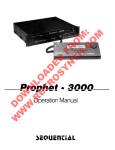
set of Burn-In Test Adapters.
Figs. 2 to 5 show pictorial
of each individual
adapter.
and schematic
representations
Depending on the type of Control,
(TNC with either
a standard
SE interface
or with an external
PLC I/O Board) the appropriate adapters must be connected as shown in fig. 1.
It is important to have the correct test program for the
type of Control and for the Control's
current NC Software
issue. The test programs are listed on page 20. The type of
Control can be determined from the identification
number of
the unit; the issue of the NC Software can be determined from
the NC Software issue number. Both these numbers are found on
the type-plate
on the rear of the Control.
~~IU~NI-IAIN
DR. JOHANNES
D-8225Traunreut
HEIDENHAIN GmbH
.Tel.(O8669)31-0
Kundendienst
Application
of
the
Bum-In
I
Test
SERVICE MANUAL
Page 19
Section
2.2.6
TNC 151
HEIDENHAIN
SERVICE MANUAL
Page 20
Section
2.2.6
DR. JOHANNES HEIDENHAIN GmbH
D-8225Traunreut~Tel.
(08669) 31-O
TNC 151
Kundandienst
Burn-In
Test
on the
Philips
Control
TYP=
151
for
miniature
A
A
FrOUl
NC Software
issue
229
134 99
229
134
95
229
134
134
99
95
229
TNC 151
cassette
Control
Id. No.
TNC 151 A
TNC
Programs
. . .
. . .
. . . 06
. . . 06
Test
dialogue
D
GB
Test Prog.
Id. NO.
230
230
600
601
01
01
Burn-In
Test
on the
Philips
Programs
for
miniature
cassette
From
NC Software
issue
Control
Type
Control
Id. No.
TNC 151 P
229 136
99
229
136
95
229
136
99
229
136
95
TNC 151 P
TNC 151 P
Test
dialogue
Test Prog.
Id. No.
. . .
. . . 06
D
230
602
01
. . .
. . . 06
GB
230
603
01
r-7 HEIDENHAIN
w
DR.JOHANNES
HElDENHAlN
SERVICE MANUAL TNC 151
Page 21
Section
2.2.6
GmbH
D 8225Traunreut~Tel.(08669)
31-O
Kundendienst
Fig.
1 Interconnections
of
Burn-In
Adapters
and
TNC 151
150A
,-in
nooprer
I II
L'TNCK5
TNC155 Zusiitzl. Burn-in Ad ter
Additional Burn-in AT apter
a)
TNC 151 A/E
/
b)
TNC 151 P/V
HEIDENHAIN
DR. JOHANNES
D-8225Traunreut
SERVICE MANUAL TNC 151
Page 22
Section
2.2.6
HEIDENHAN GmbH
'Tel. (08669) 31-O
Kundendienst
Fig.
2 TNC 150 A Burn-In
Adapter
(Id.
No.
224
874
ZY)
Xl>
Ail
i‘,‘
J‘il
,116
Schematic
of interconnections
Burn-In
Adapter
to the Control.
created
by
connecting
the
TNC 150 A
HEIDENHAIN
SERVICE
MANUAL
Page 23
Section
2.2.6
DR. JOHANNES HElDENHAlN GmbH
D-8225 Traunreut .Tel. (08669) 31-O
TNC 151
Kundendienst
Fig.
‘..r
3 TNC 150 P Burn-In
Adapter
(Id.
No.
224 875
ZY)
.*.
”
Schematic
Burn-In
of interconnections
Adapter
to the Control.
created
by
connecting
the
TNC 150 E
r
m
1 HEIIJENHAIN
DR. JOHANNES
D 8225Traunreut
HEIDENHAIN GmbH
'Tel.(O8669)
31-O
SERVICE
Page 24
Section
Kundendienst
Fig.
4 PLC Adapter
(Id.
No.
224 873
MANUAL TNC 151
2.2.6
ZY)
Internal
Additional
facility
circuitry
circuitry
schematic:
for overload
Internal
Standard
bipolar
circuitry
circuitry,
switch-over.
schematic:
with
unipolar/
m
HEIDENHAIN
DR JOHMINES
D 8225Traunreut
SERVICE MANUAL
Page 25
Section
2.2.6
HEIDENHAJN GmbH
‘Tel. (08669) 31-O
Kundendienst
Fig.
5 TNC 155 Additional
Burn-In
Adapter
(Id.
No.
228
881
ZY)
r----
s&pin
14-pin
_---
7-pin
Internal
connections.
--
1
TNC 151
SERVICE MANUAL TNC
Page
26
section
Kundendienst
Loading
(Burn-In
the Burn-In
test
test
loaded)
1. Connect the Magnetic Tape Cassette Unit
V-24 socket on the sear of the Control.
(ME 101/102)
to the
2. Prepare the ME unit to down-load the test program to the
Control by inserting
the appropriate
program cassette (see
list,
page 20) and pressing the following
buttons:
I-
1’
2.2.6
The necessary code number for reading in the Burn-In
program is entered by pressing the following
keys:
program
program not already
151
1
El-
as often
as necessary
to obtain
test
the display:
"CODE NUMBER=", and then:
(Errors in entering
these numbers can be corrected
sing clCE )4. The data transfer
is then initiated
by pressing:
by pres-
E3l
During the loading
unit, the following
of the Burn-In
dialogue will
test
program
be displayed:
from the NE
"POWERINTERRUPTED
EXTERNAL DATA INPUT"
Fig.
6 Initialization
of ME unit
3. Control must now be prepared:
After applying power to the Control,
ries out a memory test. During this
“MEMORY
If necessary, the MB unit will first
rewind the cassette
before transmitting
the data, blockwise,
to the Control.
user-programs
already loaded/programmed
into the Control
will be unaffected
by loading the Burn-In test program.
it automatically
time the dialogue
Car-
TEST"
will be displayed
on the MU.
Upon completion of this test,
by
"POWER INTERRUPTED".
the dialogue
will
be replaced
tape
Any
5. The Burn-In test program occupies both tracks of the cassette tape. Consequently,
when all the data from the first
track has been transferred,
the following
dialogue will be
displayed:
"EXCHANGE CASSETTE - ME START
EXTERNAL DATA INPUT"
To complete the data transfer,
turn over the cassette and
press the START button on the ME unit. The VDU will again
display the dialogue.
HEIDENHAIN
DR. JOHANNES HEIDENHAIN
D-6225Traunreut~Tel.(08669)
SERVICE MANUAL TNC 151
Page 27
Section
2.2.6
GmbH
31-O
Kundendienst
"POWER INTERRUPTED
EXTERNAL DATA INPUT"
6.
After
completion
will
rewind
the
question
"EXTERNAL
UNIT
Any other
display
an incorrect/faulty
of a sucessful
data transfer,
the ME unit
cassette
and the VDU will
display
the
CONNECTED
implies
test
?"
either
program
a transmission
cassette.
error
or
Fig.
7 Loading
and
Initialization
of
Burn-In
Test
Program
HEIDENHAIN
SERVICE MANUAL
Page 28
Section
2.2.6
DR. JOHANNES HElDENHAlN GmbH
D-8225 Traunreut ‘Tel. (08669) 31-O
TNC 151
Kundendienst
Re-initialization
of
a previously
loaded
Burn-In
test
program
The possibility
exists
that
the Burn-In
test
program
has been
loaded
and then the power
removed.
In this
situation
the buffer
batteries
will
maintain
the program
in memory until
the mains
is restored.
It is also
possible
that
the system
has been warm-booted,
during
the execution
of the Bum-In
test,
by pressing
Under
both
of
to be followed
The
test
Control
takes
‘MEMORY
will
Upon
by
will
automatically
approx.
17 sec.
IMPORTAIJT
Only press
the following
the Burn-In
carry
during
procedure
is
test
program:
out a memory check.
which
time the dialogue
This
TEST"
be displayed
completion
"PRESS
these
circumstances
in order
to restart
of
on the VDU.
this
test,
the
dialogue
will
be replaced
NOENT KEY"
the
key
if you wish
to cram
the normal
operating
To restart
the Bum-In
the Burn-In
test
system.
t&t
priqramm
program
press
and return
to \
The
Any
and
following
dialogue
"EXTERNAL
UNIT
other
display
the program
will
CONNECTED
then
be displayed:
?"
implies
an error
in
must be reloaded
from
the
the
stored
cassette.
test
program
HEIDENHAIN
SERVICE MANUAL TNC 151
Page 29
Section
2.2.6
DR. JOHANNES HEIDENHAlN GmbH
D-8225 Traunreut ‘Tel. (08669) 31-O
Kundendienst
Continuation
of
The remainder
in conjunction
1. Beginning
of the initialization
with
the flow
diagram
with
the display
"EXTERNAL
the
UNIT
Bum-In
test
CONNECTD
procedure
of figure
.
2.
must be described
9, page 31
?"
which
refers
to the use of an externai
operator
must respond
by pressing
.
The lines
of dots
represent
the individual
keys
in each of
the four
keying
fields.
The keys must now be pressed
once
in a defined
sequence,
each,
in order
that
the Control
can
check
that
each key is making
contact
and delivering
the
correct
code to the keyboard
interface.
The keying
sequence
is as follows:
top right
set of 20 keys
=I
b)
top left
set of 10 keys
middle
left
set of 20 keys
Cl
d)
bottom
right
set of 10 keys
In each case,
the sequence
is from
left
to right,
beginning
with
the top row.
For each correct
key-push,
the respective
dot on the VUU
will
be replaced
with
a. "*".
If an incorrect
code is received,
the keyboard
test
will
start
again
from the beginning.
initialization
test
computer,
the
”
A check
is now automticall$
carried
out,
test
program
data has nbt been corrupted
error
is detected,
the display
tb ensure
that
in any way.
If
the
an
If the keyboard
before
a power
is not displayed.
has been stored
the sequential
"REREAD-IN
PROGRAM XXXX
CHECK SUM ERROR"
will
from
3.
appear
on the
the ME unit.
VDU,
and
the
test
If the keyboard
test
has not already
prior
to a mains
interruption)
the
this
test
will
now be displayed:
"JUMP
The
OVER KEYBOARD
keyboard
test
can
TEST
program
been
option
must
be reloaded
carried
out
of carrying
be skipped
by pressing
the
key
q
Any other
case the
.
.
.
.
.
.
.
.
.
.
.
.
.
.
.
.
key will
following
.
.
.
.
.
.
.
.
.
.
.
.
.
.
.
.
cause
display
4.
If the keyboard
test
an error
message
has
error
message
will
be
for
an interrupt
(see
5.
In the case of a Control
designed
for
PLC I/O Board,
the following
text
will
following
a successful
keyboard
test:
(eq.
out
?"
"0,
the test
to be carried
will
appear
on the
. . . . . . . . . . ..E
..E
. . . . . . . . . - . . E
..E
out,
VDU:
in
which
test
has previously
been carried
out (eq
failure),
the option
of carrying
out the test
In this
case,
assuming
no errrx
message
from a previous
run,
the program
jumps into
tests
(see page 32).
1,
OR 2 PC-BOARD
has previously
been carried
been stored
from an earlier
displayed
and the program
point
7).
use with
appear
out,
and
run,
this
will
wait
an external
on the VDU,
?"
This
refers
to the number of
nected
to the Control
during
with
the appropriate
numeric
external
the test,
key.
PLC I/O Boards
conand must be answered
7 HEIDENHAIN
mlh
SERVICE MANUAL TNC 151
Page 30
Section
2.2.6
DR. JOHANNES HEIDENHAJN GmbH
D-8225 Traunreut ‘Tel. (08669) 31-O
Kundendienst
6.
The final
step
of the full
initialization
calibration
of the two potentiometers
the Control.
These must be adjusted
procedure
is the
on the front
panel
of
to give
the display:
"TEST INT.PCT,
BATTERY TRIGGER
OVERRIDE POT ADJUST:
100
SP. ROT. SPEED ADJUST:
100"
If necessary,
the caps of the knobs
securing
screws
slackened,
and the
tightened
in the 100% position.
7.
must
knobs
be removed,
the
realigned
and
At the beginning
of the initialization
procedure,
interruptions
of the program
are inhibited.
After
completion
of
the initialization,
interrupts
are enabled
to permit
jumps,
at any time,
to various
points
in the test
procedure.
Once the interrupts
have been enabled,
the test
program
can
be interrupted
by pressing
one of a number
of keys.
The keys:
fbr example,
initialization
cause restarts
routine,
as
System
isl
q
re-boot
“EXTERNAL
"JUMP
"0,
1,
at various
points
during
shown in figs.
8 and 9.
UNIT
CONNECTD
OVBRKBYBOARD
OR 2 PC-BOARD
?"
TEST ?"
?"
"TEST INT.POT,,BATTERY
TRIGGER
OVERRIDE POT ADJUST:
100
SP. ROT. SPEED ADJUST:
100"
the
Other
interrupts
the following
are
section.
also
possible;
these
are
described
in
1 HEIDENHAIN
llllllh
SERVICE MANUAL
Page 31
Section
2.2.6
DR. JOHANNES HEIDENHAJN GmbH
D-8225 Traunreut .Tel. (08669) 31-O
Kundendienst
Fig.
9 Complete
initialization
of
the
Burn-In
test
program
TNC 151
7 HEIDENHAIN
Ih
SERVICE MANUAL TNC 151
Page 32
Section 2.2.6
DR. JOHANNES HElDENHAlN GmbH
D-8225 Traunreut ‘Tel. (08669) 31-O
Kundendienst
sequential
(duration)
tests
Before starting
these tests, check that all test adapters are
including
the connection to the V-24 intercorrectly
connected,
face socket.
The following
tests
are included:
a) Key El
"TEST INT.POT, BATTERY TRIGGER"
- Front panel potentiometers
must be set to 100 2 2%
b) Key cl0
"EPROM TEST CPU"
- The check-sums of all EPROMs accessible
Processor Board CPU are checked.
cl Key El
"RAMTEST CPU BOARD
- Checks the RAM on the Main Processor
to the Main
h) Key
El
"INPUT/OUTPUT TEST 1. PC BOARD" (only TNC 151 P)
The PLC I/O Board outputs are resistively
loaded and connected to the inputs by means of the PC Burn-In Adapter. Each
output is connected to 2 inputs. By writing
"1"s to the outinputs, the Control is
puts, and checking the corresponding
able to deduce whether a fault is on an input or an output.
If a fault is detected
(a "0" on an input) the input conditions are displayed
on the VDU:
eg. :
"INPUT/OUTPUT TEST 1. PI& BOARD
OUTPUT (or input) FAILURE ,~
INPUT
0
20
40
60
01234567890123456789
01111111111111111111
11111111111
111111111111
1111
01111111
1111111
Board
BURN IN TIME: x,x HRS"
d) Key El
"RAMTEST MEMORYBOARD"
- checks the RAM on the Memory Board.
This test must not be interrupted
by a mains failure
q
e) Key
"TEST PC PAM"
- Checks the RAM where the PLC data is held
inputs, outputs,
timers, counters etc).
always a zero
Input 31 is used to monitor a 20 ms monostable pulse generated on the Emergency Off output.
If the duration
of this
pulses falls outside its tolerance
limits,
a fault condition will be displayed:
eg. : "MONOFLOPTIME TOO SHORT 2OMS"
(markers,
This pulse can be generated manually by individual
PrOoEing
of the key cl+ or, repetitively,
by pressing the key site
in
quick succession.
This repetitive
mode will be indicated
by
a "1" at input position
31 on the VDU.
f) Key El
"TEST STATIC RAM
CLP PROCESSORBOARD"
g) Key El
"PC INSTRUCT DECODER, ACCU-FF TEST"
The circuitry
used for decoding and carrying
instructions
is tested.
'i
To aid in locating
an I/O fault,
each output
individually.
By pressing the key
out the PLC
can be driven
El
(after
a short delay) the VDU will display the input
tions when only output 0 is being driven high.
condi-
I
I
HEIDENHAIN
DR. JOHBNNES
SERVICE MANUAL TNC 151
Page 33
Section
2.2.6
HEIDENHAIN
D-8225Traunreut
GmbH
.Tel. (08669) 31-O
Kundendienst
-
eg. : 'INPUT01234567890123456789
0
10000000000000000000
00000000000010000000
20
40
60
0001
\
All
i)
(always
a "1")
EO, E32
the key
n)
El
successive
outputs
(in ascending
or in descending
order
with
the
outputs
can
El
be cleared
with
the
order)
to
2OhV,
w,
j)
Key El
"TEST V24-INTERFACE"
k)
Key El
"TEST 3D-SCANNER
INTERFACE"
- Checks
the interface
to the
f) Key
q
"TEST SERIAL
the
HANDWHEEL
interface
INPUT"
to the
9,5v
Touch
o)
TEST"
values
of the
system
inputs.
Key El
"TEST REFERENCE IMPULSE INPUT"
- Checks
the effect
of a signal
pulse
inputs.
circuitry
applied
to
which
the
moni-
reference-
q
Key
"TEST TRANSDUCER INPUTS,
EXE"
- Checks
the effect
of signals
system
inputs.
applied
to
the
measuring
key
Key
"EXT. PDT, ANALCG OUTPUT TEST"
Five
external
relays
within
the TNC 150 A/P Burn-In
driven
from outputs
Al6 - A20, are used to connect
logue
outputs
X, Y, Z, IV, S, in turn,
to the ext.
pu%(see
figs.
2/3 pages
22/23).
The test
is made
different
voltages:
- Checks
be driven
key
a
q
tc
"SUPERVISION
CIRCUIT
- checks
the threshold
tors
the measuring
00000000000000000000
OUTPUT AO, INPUTS
Subsequent
pressing
of
allows
high,
ml Key
Fault
recognition
The detection
of a fault
will
be displayed
on the VDU.
The test
cycle
will
be halted
and the Burn-In
Time stops.
If
one or more faults
arise
during
the execution
of the Burn-In
test
program,
the fault
message
associated
with
the first
fault
will
be stored.
The stored
message
can be retrieved
at any time
by pressing
the key
This
causes
a system
re-boot,
as explained
All
fault
messages
can be cleared
with
the
Probe.
HE 310 Handwheel
Adapter,
the anapot.
inat three
Starting
the sequential
tests
The test
sequence
can be started,
or restarted
at any point
by
pressing
the appropriate
key.(eg
key
8 to begin
with
the V.24
interface
test.)
All
15 keys associate $
with
the sequential
tests
act as interrupts
to the Burn-In
test
program.
Unit
This
ning
key
with
also
the
El
causes
a restart
of
test
"TEST INT.POT,
on page
key
30.
the sequential
tests
BATTERY TRIGGER".
begin-
HEIDENHAIN
SERVICE MANUAL TNC 151
Page 34
Section 2.2.6
DR. JOHANNES HEIOENHAlN GmbH
D-8225 Traunreut .Tel. (08669) 31-O
Kundendienst
Individual
test runs
Each of the individual,
seouential tests can also be made to
run cyclically.
To do this; the test program must be interrnpted with the key
Calibration
Interrupting
check of the Anelogue Board ("TRIMMING ROUTINES")
the Burn-In test program with the key
El
The VDU will
then display:
"1 = CYCLIC
2 = STOPAT FAULT"
Within
ted:
Option 1 means that the test (still
to be selected) will be
run cyclically,
regardless of whether a fault is detected.
Option 2 means that the test will be run cyclically
until
such time as a fault is detected.
When one mode OT the other has been selected, the VDU will
display:
"SELECT TEST"
The desired test must then be selected with the appropriate
key.
Another possible interrupt
to the Burn-In test program is by
means of the key
El
With this key the entire
played on the VDU.
set of ASCII characters
the calibration
mode the following
tests
performance *
- Key cl1 : Reference amplifier
("TRANSMISSION BEHAVIOUR REF. AMP.")
- Key
q
- Key
q
- Key
q
- Key
q
can be dis-
: Analogue output voltage **
("ANALOGVOLTAGEOUTPUT")
: 32-step monotonic DAC *
("MONOTONIYDAC; 32 STEPS")
: DAC performance *
("TRANSMISSION BEHAVIOUR DAC")
: +/- 1ov analogne output **
("DAC + ANALOGOUTPUT+/- 1OV")
- Key 0.6 : Lrnearity
("DAC +
- Key
0
*
l
q
text
these
of analogne output *
ANALDG OUTPUTLINEARITY")
: Battery voltage check **
("TEST BATTERYVOLTAGE")
in brackets
tests
are
* Bee follaing
appears
on
not
suitable
l xp1nNtions:
VDU
for
custmr
ye,
can be selec-
HEIDENHAIN
SERVICE MANUAL TNC 151
Page 35
Section
2.2.6
DR. JOHANNES HEIDENHAIN GmbH
D-8225 Traunreut ‘Tel. (08669) 31-O
Kundendienst
q
Key
: Analoque
output
voltaqe
The performance
of the analoque
output
circuitry
can be checked
by connecting
a DVM to each of the analoque
outputs
(eq X-axis:
pin 2) and selecting
this
test.
Using
the keys
Jl,
pinl,
w.s.t.
24,4mV,
244mV and 2.44V respecincrements
of 2,44mV,
can be sunned
at at each of the analoque
outputs
(X, Y,
S).
the X key is pushed
5 times,
the Y key 3 times,
and the
key once,
the output
voltage
should
read:
(5 x 2,44
mV) + (3,x,24.4
mV) + ( 1 x 2.44
V) = 2,5254
V
voltage
tively
z, IV,
if
eq.:
IV
The polarity
The
output
of
the
can be
Keyq : +/- 1ov
output.,can
cleared
using
analogue
output
be reversed
the
The analogue
outputs
should
generate
+lOV.
The polarity
can be reversed
using
the
key
key
their
maximum
as in test
2.
Key a:
Battery
voltage
check
A "1" will
be displayed
on the VDU if
adequate,
otherwise
a "0" is displayed.
the
battery
output
of
voltage
is
m
HEIDENHAIN
u
D? JOHANNES HEIDENHAIN GmbH
D 8225 Traunreut ‘Tel. (08669) 31-O
SERVICE
MANUAL TNC 151
Page 36
Section 3
3. Exchange Information
U&e: All inputs/outputs
from the TNC 151 Control can only be
connected to circuits
which have voltages
conforming
to
VDE 5.73 S8.
Do not disconnect
or connect
plugs
under power!
NC machines also need protection
and installation
safety as
required
for manually operated machines (e.g. EMERGENCYSTOP).
Their function
should be checked during commissioning
of the
machine and of a new Control.
Before exchanging a Control
noted or stored on magnetic
the machine parameters
tape!
should be
HEIDENHAIN
SERVICE MANUAL TNC 151
Page 37
Section
3.1/3.1.1
DR. JOHANNES HEIDENHAN GmbH
D-6225 Traunreut ‘Tel. (08669) 31-O
Kundendienst
3.1 Exchanging
Control
Units
3.1.1
Procedure
for exchanging
the TNC 151 A/E Control.
1. Gain access to the rear of the Control.
2. Remove the mains
supply.
3. Remove the connector
box cover-plate
from the rear of the
Control.
4. Mark the measuring
system plugs
(X,Y,Z,IV,
Electronic
Han&heel)
and remove them.
5. Disconnect
the VDU from the Control.
6. Disconnect
the Handwheel
Unit
from the Control
(if present).
7. Disconnect
any external
data devices.
8. Disconnect
connector
strips
Jl-J6,
using
a screwdriver
to
prise
the connectors
apart
(Do not unscrew
individual
wires).
prise
art
screwdriver
with
a
cable
removing
the fixing
screws if
9. Remove the faulty
Control,
not already
removed
in 1.
10. Install
the new Control
- check the voltage
selector
position.
11. Check the fuse-rating
(see type-plate).
12. Reconnect
all cables
previously
removed.
13. Obtain
from the type-plate
the Control's
Id. No.,
NC and
PLC Software
Nos.,
and write
them in the machine
handbook.
14. Refit
the connector
box cover-plate.
15. Turn on the mains voltage.
16. Reprogram
the machine
parameters.
17. TNC is now ready to use.
HEIDENHAIN
SERVICE UANUAL
Pago 38
Section
3.1.2
DR. JOHANNES HEIDENHAIN GmbH
D-8225 Traunreut .Tel. (08669) 31-O
TNC 151
Kundendienst
3.1.2
1.
2.
3.
4.
5.
6.
7.
8.
9.
Procedure
for
exchanging
the TNC 151 P/V Control
Gain access
to the rear
of the Control.
Remove the mains
supply.
Remove the connector
box cover-plate
from the rear
of the
Control.
Mark the measuring
system
plugs
(X,Y,Z,IV,
Electronic
Handwheel)
and remove
them.
Disconnect
the VDU from the Control.
Disconnect
the Handwheel
Unit
from the Control
(if
present).
Disconnect
any external
data devices.
Disconnect
connector
strips
Jl-J3,
using
a screwdriver
to
prise
the connectors
apart
(Do not unscrew
individual
wires).
Remove the connecting
cable
P2 to the PL 100 B/110
B from the
Controls.
I
10.
11.
12.
13.
14.
15.
16.
17.
18.
removing
the fixing
screws
if
Remove the faulty
Control,
not already
removed
in 1.
Install
the new Control
- check
the voltage-selector
position.
Check
the fuse-rating
(see type-plate).
Reconnect
all
cables
previously
removed.
Obtain
from the type-plate
the Control's
Id. No.,
NC and
PLC Software
Nos.,
and write
them in the machine
handbook.
Refit
the connector
box cover-plate.
Turn on the mains
voltage.
Reprogram
the machine
parameters.
TNC is now ready
to use.
I
II
-.?
6113
8113
10
r.
'.
lleIuel\nAllu
DR. JOHANNES
D-8225 Traunreut
HElDENHAlN
‘Tel. (08669)
GmbH
31-O
Kundendienst
3.1.3
1.
2.
3.
4.
5.
6.
7.
Procedure
for exchanging
the PLC I/O Board
of the PL 100 B/110 B
Remove the fixing
screws of the heatsink
cover-plate.
Remove the heatsink
cover-plate.
Disconnect
the TNC 151 connecting
cable.
Disconnect
connector
strips
Jl-J9,
using
a screw driver
to prise
the connectors
apart.
(Do not unscrew
individual
wires)
Remove the voltage
supply
(+24V and OV)
Remove the fixing
screws of the PL 100 B/110 B unit.
Install
the new unit
following
the above procedure
in
reverse
order.
SERVICE MANUAL TNC 151
Page 39
Section
3.1.3
HEIDENHAIN
DR. JOHANNES
D-8225
Traunreut
HElDENHAlN
SERVICE
Page 40
Section
GmbH
.Tel.(O8669)31-0
MANUAL TNC 151
3.2
Kundendienst
3.2 Board
Exchange
Board
Arrangement
The TNC 151 consists
of three
main sections:
1) The frontplate/Keypad
Board
assembly;
2) The housing/Connector
Board
assembly,
with
five
plug-in
boards,
namely:
.Memory
Board
.Main
Processor
Board
.CLP Processor
Board
.Analogue
Board
.either
SE Board
TNC 151 A/E
or PLC Interface
Board
TNC 151 P/V
Power Supply
Unit
and Terminal
3) The backplate,
assembly.
Board
arrangement
TNC 151 A/AR/P/PR
TNC 151 E/ER/V/VR
PLC 3L/O Board
TNC- -51
3
P
(224~
389/223
Connector
691)
Board
(227.267)
Board
(22:
Power
(227
=4/228
Supply
(with
\
Board
601)
PLC Interface
(226
16!)\
Bwrd
761)
TNC 151 P/V)
SE Board
- -,
(with
TNC 151 A/E)
Analog
(222
Board
50~2/223
CLP :Processor
(222
580/229
Main.Processor
Memory
(224
Keypad
(224
550)
Board
133)
Board'
Board
843/230
Board
825)
/
400)
/
1
llEllJENllAlN
DR. JOHANNES HEIDENHAIN GmbH
D-8225 Traunreut ‘Tel. (08669) 31-O
caution:
.Please observe MOS protection
measures when exchanging boards.
.Exchange boards with the same assembly no. only.
The assembly no. is impressed on every board, on the
left of the serial no.
SERVICE MANUAL TNC 151
Page 41
Section 3.2
Work area requirements
The TNC 151 contains sub-assemblies
with MOS elements.
Although MOS ICs are equipped with an input protection
diode
network, to eliminate
the build-up
of static charges care must
be taken when handling these elements.
The following
requirements
in the work area must be met:
Prior to working with MOS components or with assemblies containing
MOS elements, all table coverings,
instruments,
tools,
end work personnel must be properly
grounded.
A portable
"MOS-HANDLING-SET" for field
when exchanging the operating
software
TNC 151:
service
is necessary
and/or servicing
the
1
a conductive
work surface
2
a wristband
that provides
en electrical
connection
between person and conductive
work surface
3
a cable
between
that equalizes potential
differences
conductive
work suface and ground
HEIDENHAIN
DR. JOHANNES HElDENHAlN
D-8225Traunreut.Tel.(08669)31-0
SERVICE
MANUAL TNC 151
Page 42
Section
3.2
GmbH
Kundendienst
Exchanging
the pluggable
boards
Unscrew
the 5 mounting
screws
and remove
the housing
cover.
Removing
the boards:
Press
the board
ejector
keys outwards
and pull
out the individual
board
form the top.
Analogue
Board
Before
removing
the Analogue/Analogue
TTL Board
pull
off
and
mark the connector
plugs
for the measuring
system
inputs/
square
wave signal
inputs
and the electronic
handwheel
input.
The connector
sockets
on the board
are coded with
coding
pins.
I
.3
,
j
_Insezting
the boards:
The connectors
of the boards
is therefore
avoided.
Press
tor
Board
using
the ejector
Main Processor
When exchanging
IC-P19
on the
Main Processor
are coded:
incorrect
the board
firmly
into
keys
tilted
inwards.
and CLP Processor
Board:
these
boards
insert
program
CLP Processor
Board
and IC-P4
Board.
insertion
the Connec-
EPROM's IC-P3
and
to IC-PlO
on the
Board:
During
the exchange
or removal
of the Memory Board
the buffered
RAM will
no longer
be supplied
with
voltage,
which
means that
the machine
parameters
and any user-programs
will
be lost!
Before
inserting
the new Memory Board
plug
in the relevant
EPROMs (EPROM IC-Pll-to
IC-P18),
paying
particular
attention
to their
correct
location
and orientation.
Memory
HEIDENHAIN
DR. JOHANNES HEIDENHAN
D-8225Traunreut.Tel.(08669)
SERVICE MANUAL TNC 151
Page 43
Section 3.2
GmbH
31-O
Kundendienst
Exchanging the Keypad Board:
.Remove the 6 cross-head
fixing
screws from the frontplate.
.Tilt
the frontplate
outwards.
.Remove connectors J13 (feedrate-override
potentiometer)
and
J14 (spindle-override
potentiometer)
from the Connector
Board.
.Remove the ribbon cable connector PlO from the Keypad Board.
.Remove the 7 cross-head fixing
screws which secure the Keypad Board to the frontplate.
.Pull off the Keypad connectors,
Pl to P8 from the Keypad
Board.
.Remove the Keypad Board.
When rebuilding
tors are firmly
the LEDs project
keypad housing.
the assembly, ensure that the keypad connecengaged in their respective
sockets, and that
through the corresponding
bored holes in the
Ih
7 HEIDENHAIN
DR. JOHANNES HEIDENHAIN GmbH
D-8225 Traunreut .Tel. (08669) 31-O
SERVICE MANUAL
Page 44
Section
3.2
TNC 151
Kundendienst
Exchanging
the Power Supply
Unit:
.Remove
the 4 cross-head
mounting
screws
from the rear
of the
Control
(2 screws
are found
in the connector
box).
.Remove
the back wall
with
the Power
Supply
Unit
and Terminal
Board.
.Disconnect
the ribbon
cable
connector,
PI,
from the Connector
Board
(see diagram).
.Remove
the voltage
supply
plug,
P2, from the Connector
Board
(see diagram).
Exchanging
the Connector
Board:
.Remove
the 2 cross-head
fixing
screws
of the V.24 connector
on the rear
of the Control.
.Push the V.24
socket
through
its
recess
in the Control
housing.
.Unsolder
the connectors
to the MU socket
from
the Connector Board
(solder
terminals
1,4,5,6,7,8,10).
Note the colour
of the wire
connected
to each terminal.
.Pull
the Connector
Board
from the front
of the Control
housing.
Comector Board
‘I
HEIDENHAIN
DR. JOHANNES
D-8225Traunreut
SERVICE MANUAL TNC 151
Page 45
Section 3.3
HEIDENHNN GmbH
'Tel. (08669)31-O
Kundendienst
3.3
Software
The dialogue
language of the TNC 151 is determined by
IC-PlO (located on Main Processor Board) and is discernible
from the different
Id. NOS. of the programmed EPROMs.
Exchange
The TNC 151 operating
software
is stored
in 17 EPROMs.
- IC-P3, IC-P19 (CLP Processor Board)
- IC-P4... IC-PlO (Main Processor Board)
- IC-Pll..IC-P18
(Memory Board)
Every operating
Software No.
example:
software
is specified
with
an 8 digit
227 001 06 complete software Id. No.
227 001
primary software Id. No.
06 update software index
Each of the 17 progranuned
specified
with an 8 digit
EPROMs (IC-P3...IC-P19)
Id. No.
is
Following
GWXllan
English
French
Italian
Spanish
Swedish
Finnish
Dutch
227 116 CG complete Id. No. of the Prog. EPROM
227 116
primary Id. No. of the Prog. EPROM
C position
on the board
(C = IC-P12, IiEXadecimal counting
llla**er)
G update index
The operating
software
(IC-P3...IC-P8,
(IC-P9)
IC-PlO...IC-P19)
TNC 151 A: Control
with
o NC software and
o PLC standard software
TNC 151 P: Control
with
o NC software and
o PLC standard software,
PLC custom software
or
at this
time
IC-P9 (PLC software)
The standard PLC program (EPROM position
IC-P9)
can be replaced with a custom PLC program for
the TNC 151 P.
IC-P3
The export NC Software differs
NC Software in EPROMposition
in
o NC software
0 PLC software
are available
CD)
(GB)
(F)
(I)
(E)
(S)
(SF)
(NL)
The dot matrix
includes
languages
The Id. No. of the other programned EPROMs are the
same (for a given IC position)
in all languages.
(prerequisite:
same software issue!)
Exception:
example:
dialogue
IC-P19
for
(character
all
VDU displayed
generator).
from the standard
IC-P3.
characters
is contained
SERVICE MANUAL
Paqe 46
Se&ion
3.3
TNC 151
Kundendiemt
Illustration
Illustration
2
Memory
Board
224 843
230 400
../
..
3
Main
Processor
left:
below:
Board
222
Arrangement
Arrangement
509
..
of
of
4
PCBs in the Control
EPROMs on the various
CLP Processor
Board
boards
222
580
I
..
HEIDENHAIN
SERVICE MANUAL TNC 151
Page 47
Section
3.3
DR. JOHANNES HElDENHAlN GmbH
D-8225 Traunreut ‘Tel. (08669) 31-O
Kundendienst
Software
Exchanae
Caution:
When exchanging
the
protection
procedures!
o The cover of the
the 5 cross-head
Control
mounting
o To exchange
the program,
- Memory Board
- Main Processor
Board
- CLP Processor
Board
have to be removed~from
Thereto,
outwards,
protection
software
observe
the
can be removed
after
screws (top side)
the following
2
3
4
the assembled
lift
the board ejector
pull
out board from
mat.
- After
the software
exchanqe
has been concluded,
the Id.-Nos.
the NC and PLC software
have to be chansed.
The description
plate
for the software
numbers
is found-on
the rear of-the
Control
under the type-plate.
MOS
unscrewing
boards
Control
keys and press
above and lay onto
Id. NO.
'
NC Software
No.,PLC Software
No.-
MOS
o Push screwdriver
blade
carefully
between EPROM and socket,
remove EPROM with extraction
tool
and place
onto MOS
protection
mat.
o Insert
Important:
EPROM into
appropriate
- When exchanging
number
(second
EPROM Id. No..
socket
insertion
EPROMs, observe
the
to last
digit
of the
hexa-decimal
counting
- The EPROM package
direction
as the
- Visually
respective
using
check if
sockets
index must point
ICs on the board.
tool.
position
programed
manner)
in
the
the EPROMs are contacting
after
an exchange.
same
their
The RAM &mory
of the Memory
Board is unbuffered
diving
the EPROM (software)
exchange.
The machine
parameters
and
any stored
user-program
are therefore
erased!
For continued
operation,
reentered
into
memory.
the
machine
parameters
have
to
be
of
neluelunAllu
DR. JOHANNES
D-8225Traunreut
HEIDENHAIN GmbH
.Tel. (08669) 31-O
SERVICE MANUAL TNC 151
Page 48
Se&ion 3.4
Kundendienst
3.4 Replacement
Units
Replacement
Parts
Parts,
Loan/Exchange/Service
Units
TNC 151
In general,
replacement parts are available
for all sub-assemblies discernible
from the wiring diagrams (see section 4.3).
However, it is strongly
recommended that all repairs
and maintenance work are entrusted
to an official
HEIDENHAIN agency.
No responsibility
can be accepted by DR. JOHANNES HEIDENHAIN
GmbH for repairs undertaken by anyone else.
The list on page 49 shows the Id. Nos. and names of all parts
available
for the TNC 151. These parts can be ordered from the
department Kundendienst
(Customer Service)
at HEIDENHAIN
Traunreut.
It is of utmost importance,
when ordering,
to give
(i) the Id. No., (ii) the name, in German, and (iii)
the
quantity
of each part required.
Telexed order should be sent
to the Kundendienst Telex: 17 866 982 or Teletex 866 982.
Loan, Exchange,
Service
Snits
In order to keeep machine down-time as short
HEIDENHAIN offers
a loan and exchange Senh3?.
as possible,
Loan units
Loan units are available,
free of charge, for the duration
of a repair carried
out at HEIDENHAIN Traunreut
or by an
official
HEIDENHAIN agent. The only charges to the customer
are the shipping charges.
Exchange units
An exchange unit can be requested for a unit that is returned for repair.
This exchange unit is equipped with the
latest hardware and software issue and is externally
in
excellent
condition.
The only charges to the customer in
this case are for the repair of his own unit.
Transaction
Requested loan 01
of request,
or the
is available
from
A customer's
faulty
HEIDENRAIN within
exchange units are shipped on the
following
day, provided
that the
our stock.
unit should be returned
to DR.
14 days of receiving
the exchange
date
unit
JOHANNES
unit.
Service units
Service units are new units which are used for service
purposes and can be obtained from DR. JOHANNES HEIDENHAIN
at non-repeatable
discount prices.
IlElUCNnAlN
DR. JOHANNES
D~8225Traunreut
HElDENHAlN GmbH
.Tel.(O8669)
31-O
SERVICE MANUAL TNC 151
Page 49
Se&ion
3.4
Kundendienst
Id.
No.
229 134
229 134
229 135
95
99
95
229
229
229
229
229
135
136
136
137
137
99
95
99
95
99
TNC
TNC
TNC
TNC
TNC
TNC
TNC
TNC
151
151
151
151
151
A/E mit
1280 SBtzen
(with
A/E mit 3160 Satzen
(with
AR/ER mit
1280 Satzen
AR/ER mit 3160 S?&zen
P/V mit 1280 SBtzen
151 P/V mit
3160 SZtzen
151 PR/VR mit 1280 SAtzen
151 PR/VR mit
3160 Satzen
223
223
836
216
. .
. .
PL 100 B Leistungs-Pl.
PL 110 B Leistungs-Pl.
(PLC
(PLC
212
222
300
674
. .
..
BE 111 Bildschirmeinheit
BE 211 Bildschirmeinheit
(9" VDU)
(12" VDU)
212
216
225
224
230
222
223
222
222
227
212
282
394
037
843
400
502
SSO...
509
580
601
387
.
.
.
.
.
.
.
.
.
.
.
.
.
.
.
.
.
.
.
.
Gehause,
Frontteil
TNC
GehZuse,
kompl.
GehSuse,
Tastatur-Vorsatz
Pl.,
Speicher-3160
SAtze
Pl.,
Speicher-1260
SAtze
Pl.,
Analogteil
- Sinus
Pl.,
Analogteil
- TPL
Platine,
Hauptrechner
Pl.,
Regelkreisrechner
Platine,
Netzteil
Platine,
EntstBr
(Front
panel)
(Housing
assy.)
(IS0 format
keypad)
(Memory
Brd.-3160
Blk.)
(Memory Brd.-1280
Blk.)
(Analogue
Brd.-Sinewave)
(Analogue
Brd.
- TPL)
(Main Processor
Bra.1
(CLP Processor
Bra.)
(PSU Board)
(Mains
Filter
Board)
I/O
I/O
1280
3160
blocks)
blocks)
Board)
Board)
Id.
No.
227
226
228
228
224
227
213
217
217
228
202
213
215
278
761
164
166
825
267
204
737
532
168
370
206
091
NEiIE
.
.
.
.
.
.
.
.
.
.
.
.
.
.
.
.
.
.
.
.
.
.
.
.
.
.
Platine,
SE
(SE Board)
Platine,
PC-Interface
(PLC Interface
Brd.)
Platine,
Klemmleiste
(Terminal
Brd.
for A/E units)
Platine,
Klemmleiste
(Terminal
Brd.
for P/V units)
Platine,
Tastatur
(Keypad
Board)
Platine,
Stecker
(Connector
Board)
Tastenfeld
kompl.-20
Tasten
(20-key
keypad
assy.)
Tastenfeld
kompl.-10
Tasten
(lo-key
keypad
assy.)
Halter,
Batterie
kompl.
(Battery
holder
assy.)
Potentiometer
kompl.
(Potentiometer
assy.)
SpannungswZhler
m. Si.-halterWoltage
selector+fuse)
Klemme N&z3 pol.
kompl.
(3-way
mains
corm.)
Trafo
BV 15714
(Transformer)
llellJelullAllu
DR. JOHANNES
W3225Traunreut
HEIDENHAIN GmbH
.Tel. (08669) 31-O
SERVICE MANUAL TNC 151
Page 50
Section
4/4.1
Kundendienst
4.
Additional
4.1
Block
- Input/Output
system
inputs,
Information
Diagram
enclosed
unit.
(e.g.
outputs,
keypad,
LEDs,
screen,
measuring
V.24 interfaces
etc.)
Description
General
The TNC 155 block
diagram
shows, in simplified
form,
the internal functional
units
of the control,
their
relationship
to the
various
boards,
and their
interconnections.
The graphic
layout
of the diagram
and the way it is included
in single
sheets.
- the representation
of any of the TNC 155 models
(A/AR/P/PR),
- simplified
representation
of functional
processes
Numbers
functional
facilities
analog
in
dashes
inform
about
the
board
and its
The functions
microprocessor
of the control
are
systems
as follows:
divided
"Main Processor
System"
- Keyboard,
LBDs
- User Program
Interpreter
- Provision
of programming
"environment"
- Generation
of PLC program
addresses
* - Transfer
of input
and output
states
face Board,
SE Board and PLC RAM
* - Control
of the V.24 interface
between
the
two
between
PLC Inter-
1.
2.
Simplified
-
Description
of
the
TBC 155
(Block
"CLP-Processor
System"
- Ascertainment
of instantaneous
- Interpolation
Calculations
- VDU Control
* - Demand Speed Values
to DAC
* - Interface
with handwheel
unit
Diagram)
Board
(1)
Board
(2)
Main Processor
Board
(3)
CLP Processor/Graphic
Board
(4)
Analogue
Board/Analogue
Board TTL (5)
with SE Board
(6) it corresponds
to a A(E)-Type;
without
SE Board,
with PLC Interface
(61, however
with PIG I/O-Board(s),
it corresponds
to a P(V)-Type
respectively,
PR(VR)-Type
- Power Supply
Board
(7)
- Terminal
Board
(8)
* Serial
Keypad
data
transfer
via
positions
CRU bus.
Memory
The functional
processes
of
two microprocessor
systems,
- Microprocessor
(TMS 9995)
- Program
Memory (EPROMs)
- Write-Read
Memory
(RAMS)
the control
are
each comprising:
divided
Main
Processor
Unit
- Primarily
on the main processor
- The operating
system software
is
board
held
and the memory
in EPROMs:
board.
or,
-30.1-30.3-30.3-2obetween
IC-P4
(not mapped)
IC-P5 . ..IC-P88
IC-PlO
(dialogue
language)
IC-Pll...IC-P18
Main
Memory
Proc.
Board
Board
neIurlunAllu
DR. JOHANNES HElDENHAlN
D-8225Traunreut.Tel.(08669)31-0
GmbH
SERVICE MANUAL TNC 151
Page 51
Se&ion
4.1
Kundsndienst
- The RAMS -30.2on the main processor
board can be accessed
either
by the main processor
-3O- or by the CLP processor
-4o-.
The intended
coordinates,
programmed
feed,
display
texts
etc.
can therefore
be transferred.
These RAMS also serve as register
file
memory for the main
processor
-3o-.
, and (under certain
circmUser programs,
machine
parameters
stances)
the PLC program
are programmed
in RAMS -20.1-.
- The 16-bit
address
mapper -31-.
bus
- The keyboard
controller
LEDs and scanning
the
is
extended
-32- has the
keypads
-32.1-
to
20-bit
by a memory
task of driving
the
on the front
plate.
- The main processor
is connected
with V.24 interface
-34via a (serial)
CRU-bus.
This interface
is used to exchange
data by means of a magnetic
tape unit
(ME) or, respectively,
an external
processor.
- The PLC program
contained
in IC-P9
-33.1is
'1-bit-PLC-processor"
-33- mounted
discretely
processor
board.
The input
and output
states
4k x 1 PLC-RAM -33.2-.
processed
by the
on the main
are stored
in a
- I/O-Functions:
a) TNC 151 A-Versions:
24 galvaf;ically
separated
inputs
(EO to E23) -6O- and 24
floating
relay
contact
outputs
(A0 to A22 + emergency
stop)
-61- on the SE Board.
The inputs
and outputs
are protected
on the terminal
board
(A version)
by special
protective
resistances
5.lk
ohms -8O- and 47 ohms -80.1-.
Protective
resistances
should
never be replaced
with normal
resistances!
The Analogue
outputs
are led via LC-filter
-81- as protection
against
the oscillation
of analogue
outputs.
b) TNC 151 E-Versions:
The inputs
and outputs
are loaded
on external
PLC
I/O-board
(e.g.
PL 1OOB or, respectively,
PL 100B)
which are driven
by the main processor
-3O- via the PIG
interface
board.
The data is serially
transferred
via
the CRU-bus.
All lines
of this
bus as well as the
required
addresses
are galvanically
separated
by the
optocouplers
-6O- and are converted
from the TTL level
(5V) to the MOS level
(12V) by means of a level
converter
-61-.
Thus a higher
noise
immunity
is obtained.
Under the control
of CRU addresses
63 programmable
inputs
(EO to E62) -E2- located
on the PLC I/O board are multiplexed
on CRUIN 1 line.
If 2 PLC I/O boards
are connected
the inputs
from the 2nd board
are multiplexed
on CRUIN 2.
On the PLC interface
board either
CRUIN 1 or CRUIN 2 are
selected
-64- and are led to the main processor
via CRUIN.
The serial
CRU OUT signal
is converted
in 31 outputs
via a
serial-parallel-converter
-El.l-.
The outputs
(each having
its own current
supervision
-El-)
are transferred
via line
drivers
to the machine
interface.
- An overloaded
output
only switches
off during
the period
of the overload.
- If the current
supervision
detects
overcurrent
no
emergency-stop
results
in the standard
PLC program.
The input
E63 is used to indicate
an overloaded
output
to
the main processor
-3O-.
PL 100B: 31 unipolar,
programmable
outputs
+
emergency-stop
protected
against
overload.
PL 1lOB:
26 unipolar,
programmable
outputs
+ 5 bipolar
outputs
and emergency
stop protected
against
overload.
On the PlC I/O board a 12V voltage
is generated
by an
external
24V supply.
On the PLC interface
board
this
12V
voltage
is transformed
in a 5V voltage
for its TTL modules.
ncIlJelunAll\
DR JOHANNES HEIDENHAIN GmbH
D-8225 Traunreut ‘Tel. (08669) 31-O
SERVICE MANUAL TNC 151
Paae 52
section
Kundendienst
CLP Processor/Graphic
- Primarily
Unit:
on the CLP processor/graphic
- Operating system is contained
(32k x 8).
board.
in EPROM IC-P3 -40.1-
- The main task is the calculation
of the instantaneously
intended values of the analog output voltages
dependent on:
.the instantaneous
actual positions
.the programmed intended position
.the distance of the intended position
(influence
on deceleration
ramp)
.the programed
feed rate
.the fast traverse
rate* determined per machine parameter
.the setting*
of the override
end feed potentiometer
The calculating
speed requires
a wait-free
RAM -40.2-- The measuring system signals are processed on the analog
board. These signals are amplified
at first
-50.1- and
then subdivided
-5O- by delaying
(phase shifted)
and
combining them differently.
The subdivided
0 degree,
90 degrees and RI signals are then led to the gate arrays
-42- of the CLP processor board. The gate arrays are
especially
developed LSI circuits
consisting
of different
gates and counters in which the direction
of the movement
and the number of pulses are calculated.
This information
can then be scanned by CLP processor -4O- to ascertain
the actual values of the axes.
- The symmetry, the on-to-off
ratio and the amplitude of the
system signals are constantly
controlled
by a supervision
circuit
-5O-.
4.1
- The signals from the handwheel (if present)
are shaped via
the functional
block -53- and are also processed by the CLP
processor.
- If the distance between the control and measuring system is
more then 2010, an EXE has to be interposed.
The measuring
signals are thus already amplified,
subdivided,
evaluated,
supervised
and converted
in TTL signals.
An "R" version of
the control
is used accordingly
(e.g. TNC 155 AR) equipped
with a combined EXE connection
for X-, Y-, and Z-axis and
an analog board TTL. The input amplifiers
and the wiring
for the signal subdivision
are replaced with line receivers
-5O- on this analog board whose outputs are directly
connected to the gate arrays -42- on the CLP processor board.
The supervision
signal of the EXE is also buffered
-5O- and
transferred
to the CLP processor board. The signals of the
handwheel are likewise
processed -53- as on the "normal'
(sine) analog board.
- If instead of linear position
transducers
incremental
encoders are used to ascertain
actual values a reference
pulse
appears once per revolution.
Since only one reference
pulse
is to be evaluated
all other reference
pulses of the axes
X, Y, Z, IV are inhibited
on the analog board -5O-. The
signal lines are connected with the analog board via the PLC
I/O board and the PLC interface
board. The level conversion
MOS/TTL as well as the galvanic
decoupling
is carried out
on the PLC interface
boards via -61- and -6O-.
ll~lUEN~iilN
DR. JOHANNES
D-8225
Traunreut
HEIDENHAIN
GmbH
SERVICE MANUAL TNC 151
Page 53
Section 4.1
.Tel.(O8669)31&0
Kundendienrt
- The data of the CLP processor is transferred
to the analog
outputs via the serial CRU bus. The digital
output values
calculated
for all axes are multiplexed
on the CRU OUT line
and are converted
in a 12 bit parallel
format on the analog
board. These successive digital
values are then converted
in analog values (voltages)
by means of a DAC -52.1(digital-analog-converter).
These voltages
are compared with the
adjusted values of the override
and feed potentiometers
-52- and the results
are transmitted
to the CLP processor
via CRUIN. The output voltages
can thus be adapted to the
values adjusted by the override
or, respectively,
the feed
potentiometer.
The X-, Y-, Z-, IV- and S-analog values
generated shortly one after the other at the output of the
DAC are allocated
to the single axes by means of five
sample and hold circuits
-52.2-.
The five individual
analog voltages
are amplified
and buffered
subsequently
-52.3- and are led to the terminal
board.
- On the analog board the buffer
battery
(-3,46V) and the
internal
temperature
(65O) of the control
are also supervised -51-. The supervision
signals are led to the CLP
processor via the CRUIN line.
- Two "watch dog" monoflops -51.1- are on the analog board.
These must be triggered
separately
once every 5ms by the
CLP processor -4O- and once every 2Oms by the main processor
-3o-.
If the monoflops are not driven within 5ms
or 2Dms (error state),
an emergency-stop
signal is
triggered.
- The drive of the screen is another important
task of the
TNC 151 CLP processor.
It only has to write the texts to
be displayed
into the CRT RAM -41-l-.
A special CRT controller
TMS 9937 -41- generates the necessary addresses
for the CRT RAM and the character
generator
IC-P19 -41.2so that the data are transferred
to the shift register
-41.3- in the right sequence. Thus signal can be inverted
by means of an exclusive-or-gate
-41.4- to generate an
inverse video display.
The video signal,
the bright/dark
signal,
supply
the horizontal/vertical
are used to operate
sync. signals
the screen.
and an 11V
- On the SE-board (or the PLC interface
board) the V.24
signals of the handwheel unit HE 310 are connected to the
line drivers
or, respectively,
to the line receivers
-62-.
A serial
interface
module -43- on the CLP/graphic board
stands between line receivers/drivers
and the CLP processor
to transfer
data with the handwheel unit and to format data.
(start/stop
pulse e.g.)
- The signals of the 3D-probe are buffered
via the 3Dprobe-interface
on the SE-board (or the PLC interface
board) -63- and are evaluated
via the counter module
-42- on the CLP processor/graphic
board.
nellJel\nAll\
DR. JOHANNES
D-8225Traunreut
HEIDENHAIN GmbH
.Tel.(O8669)31-0
SERVICE MANUAL TNC 151
Page 54
Se&ion
4.1
Kundendienst
Power
Supply
- +5V are
converter
coupled
operation
unit
generated
for the TTL modules
via the forward
-7O-.
The flyback
regulator
-7O.linductively
with the flow converter
generates
+/-15V
for the
amplifier.
- The +12V supply
voltage
for the V.24 interface
with the help of the +15V by means of a linear
is generated
regulator
-70.2-.
- +llV are generated
via the forward
converter
-70.3for the
TNC 151 (BE 111, BE 211) screen which in contrast
to the
TNC 155 (BE 411) screen does not have an own power supply
unit.
The switch
regulator
-70.01and -70.31readjust
the
output
voltage
load controlled.
- The soft
current.
start
-71-
limits
the
relatively
high
switch-on
- On the power supply
board there
is, moreover,
a voltage
supervision
-72- triggering
a reset
signal
if the power
supply
is interrupted
or if the supply
voltage
drops below
a predetermined
minimum
level
(167V
if set for 220V
operation)
for a short
time.
If U2 (+5V) exceeds
if there
is a failure
the overvoltage
recognition
-73- is immediately
effective
and causes the
overvoltage
protection
(thyristor)
-73.1to connect
through.
Thus Ul is short-circuited
coming directly
from
the power supply
transformer
-74- via the rectifier
-75-.
A greater
damage at the subsequent
electronics
is thus
inhibited
by means of.this
protective
measure.
r
1 nellJelunAll\
B
DF
-
fOHAN”ES
D 8725 Traunreut
HElDENHAlN
.Tel. (08669)
GmbH
SERVICE
Page 55
Section
31-O
Kundendienst
4.2
Block
MANUAL TNC 151
4.2
-
Block
Diagram
TNC 151
Diagram
Arrengement
PLC-I/O-Board
Paver
Supply
Terminal
Board
(P-Version)
Terminal
Board
(A-Version)
PLC Interface
Board
SE-I/O-Baord
Main Processor
Board
CLP Processor
Board
CLP Graphic
Board
Analog
Board
(TTL-1mpul6)
Analog
Board
Memory
Board
Memory
Board
Drawing
4820
4820
4820
4820
4820
4820
4820
4820
4820
4820
4820
4820
4820
4820
Nmber
EKD
EKD
EKD
EKD
EK!J
EKD
EKD
EKD
EKD
EKD
EKD
EKD
EKD
EKD
1603300
1605100
1605200
1605000
1604800
1604900
1604700
1603400
1603700
1603800
1603600
1603500
1603900
1604000
Page
56
57
58
59
60
61
62
63
64
65
66
67
68
69
Extern
Analogteil
Platine
ODER
ODER
-
ODER
Klemmleisten-
NetzteilPlatine
I
Stecker-
Zeichnungs-Nr.:
Iv320EK01602500
Platine
0
A~nordnung der Blockschaltbilder
jq
ODER
-.- .-.-_.-.-~-..~~~~
CRU -Adress
I,
-Bus
lnterfllte
I,
- Plut1nc
CRUINZ VM der 2 PLC-:
\
63 Eingiinge
El
Lei tungs 31 Ausgiinge
treiber
und
Stromiiberwachurq
IU Z.PLC-Em/Ausq.-Plotine
---.---
E 1.1
Auscjjnge
(Serien- 1
Parallel-C
Umsetzer) -
---~
..,.-....-.
CRUOUT. CRUCLK
1
“0” PU-Interfore-PIntIne
-Ein /Ausg.-Plntme
r---.-.-.~.-~~.-y
NOT AUS van
#y
Zclchnungs
- Nr.:
G.20 E KO 1604500
(Ex ternlPLC-EinIAusgang-
Platine
’
75
74*
-
Netr-
trans-
“N
-
Glrichrichtcr
-
formotor
schutz
73
“2,
uv-i .’
(Reset1
tflcsetl
1
I
Resetriesetiibcrwo chung
r,“Ref
Stholtregler
i
l
I
I
I
- Nr.:
4820 E~0160f+600
1
1
r-
,I
L
A
70.01
l-
72
Zclrhnungs
I mit Tiefpoflfiltert
ltTLL941
I
ijber spannungsrrkcnnung
I
I
“1
“Rcf 1,
_-------
lJ3
“H
!
-------
---FlunwandlerLcistungsI
scholtcr
i
I
lmit
---------
Tiefpoflfiltert
J
70.31
Stholtregler
ITL L9f.l
1
1
ex TV
Vorschub
--~-.-...
I
.)
Plutml
+lZV
spamungs
regk
LC Filter
Analog
/”
I
r- -I.
Analog
:
-Sperre
CRUIN
2
CRUIN
1
CRUOUT. CAUCLK
Reset
NOT AUS
Zeichnungs
- Nr.:
LB20 E KD 1604400
zq
Klemmleisten-Platine
<
. ISV Netzted
<
ov
AnalogtellPlotine
Ausgiinge
- Bus
Referenzimpuls
E
I E
I 2
-
I
CRU -Adress
I n
-
1
- Aurgcinge
PotISctllelfel
lzur Anutogtd-
(P-Verslonl
PIIt!
ext,I
Vorschub
Schlcller
11111AnrlloqtrllPlntlml
ov
,
81
)
LC -
Sp~nMWjS-
f
- Ausgiinge
Analog
NOT AUS
23 x 47 n
80.1
i
NOT AUS
23 Eingiinge
i.Zeichnungs-Nr.:
~020 E K0160&200
23 Eingtinge
Schutzwiderstiinde
23x5.1
I
kn
80
+lSV Netrteil
Anoloqtell-
- Ausgbnge
23 Ausgiinge
Schutzwider stiinde
. --.
t
9
-
regler
Filter
Analog
-
I
+lZV
ii.l
CRU - Adress
z
- Bus
a”
Referenzimpuls-Sperm
.-._.-__--_.
“on HnuptrettlllerPlotine
__----_
- zu Anologteil-Platine
I
CRUIN 2
iRUIN
:ff
1
4-
(------
v---
NOT AUS -
Zrichnungr -Nr.:
4820 E KO 16Of.3 00
I-l
111111
I
I
NOT AUS
“0”
Analogtell
Plotinc
Blockschaltbild
PLC-Interface
TNC 1511155
-Platine
/I~-----
:-3
i
CRU-Adress
“on HouptrechnerPlot ine
-Bus
teferenzimpuls-Sperre
1
- zu Anoluqteil
- Plolin~/;.-----$
NOT AUS
1
NOT AUS
24 Ei ngtinge
J
(Optokopplerl
und
Parallel /Serien
Umse tzer
24 Einghge
L
NOT AUS
AnoloqteilPlotine
Zcirhnunqs-
Nr.:
4820 E KO 16041 00
1
I
SE-Ein /Ausgang
- Platine
I” SE IPLCurn externen Computer,
Hognetbondeinheit.
usv.
!SS- Bus
I7 bi t\
Standard
30
v. 24
RS 232(
jchni tt
stelle
-u
I
I
!
“Haupt rechner”
CPU
(16bitl-Adress-Bus
Ic
E
K-P4
IIL
“I\ ”- Ia
” II
TMS 9995
fnicht
mopbarl
8)
r!
!
Erweiterter
TastenfeldConh-oller
RAM
Mapper
2vx tI
(1workspa
ce
Gkm. RAt
I)
!
AS-Al5
K-P5
:
K-P8
?c-PI0
5x
28279-S
IErwei ter t
den AdressBus 1
PLC
RAM
4kx
8kx 8
fDDiologSpache
I
I
CRU-Daten-Bus
(Tastatur-
Platinel
I
II
t-u
Standard
*
-Nr.:
Bus
.3
zu SEIPLC-Interface-Plotine
Zeichnungs
(20bitt-Adress-
-0aten
ICRUIN.
r/i!
u
\I
- Bus
CRUOUT, CRUCLK)
zulvon Regelkr-Plot.
.q 32.1
2:
m
,:g;Fg .amll*
lw
Blockschaltbild
TNC1511155
1
Standard
(16 bit I - Adress - Bus
------I\\\
1161
7?23
Regel-
kreis -
I I2k x 8 I
7
77
7
Standard
lilf
I I II.::w7-’ I
t2-
- Oaten - Bus
I”,‘““““.,‘“’
Zeichnungs - Nc:
4820 EKD16029 00
I-li%lI
I I I I I I
Regelkreis
- Rechner-Platine
Standard
(16 bit1 -Adress
- Bus
40
:
?egel,
I.PROt’
IC-Pi
kreis,
lechne
CPU
MS 99s
----f
I
I
32k xt
/
b
- I
I
L-l
CRU-ootenStandard-Daten-Bus
Zeithnungs-Nr.:
LB’20 EKO 16030 00
i-
I
I
I
I
I I I El I
zu Spicher> Platine
CRU-Adress-
Bus (van Regelkreis
YO” Houptrerh
ner-Plotine
CRU-Adress Bus
” Referenz - impulr - Sperre
1
“0” SEIPU-lnkrf-Plotme
-Platine)
II
‘
i
\’
’
CRU-Daten-Bus
(van Regelkreis
-Platine)
cN.Blockschal tbi Id TNC1511155
Zeichnunqs - Nr.:
4820 E KD 16028 00
r-1 1 1 1
I I I I
Analogteil -PlotineITTL-Eingiinge)
CRU -Adress
-Bus
Avon Regelkreis
.ulI
1
-PlatineI
,,uqJ,,cr.,-
ner- Plotine
CRU-;&es
Referenz
- lmpuls
- Seerre
tOmr I Sms
lono- I Mono
flop 1 flop
I
van Houptrechner- Platine
CRU-OatenBUS
CR&&ten-Bus
Zeithnunqs - Nr.:
&820 E KO 16027 00
(van Regelkreis
-Platine
t
u
52.1
x.4
I:
Abtost,
und
HolteSchnl.
..-.
t-..,
I
7
Speicher - Adress - Bus
-
-< u
20
EPROM
2-
20.1
RAM
IC-PI1
(Anwender
3160 Siitze)
IC -b1e
8xBkx8
32 x 2k x 8
-
/
\
/-
Zeichnungs-Nr.:
4820 EKD1603100
CRU-Daten
- Bus
Speicher - Platine
Speicher
- Adress
- Bus
u >
-
20.1
RAM
EPROM
K-P11
( Anwender
1280 Siitze)
IC -bl8
16x 2kx8
-
\
/
Zeichnungs -Nr.:
4820EKD1603200
CRU-Daten
- Bus
A
I
1
lltllJtNllAIN
DR. JOHANNES HEIDENHAIN GmbH
D-8225 Traunreut ‘Tel. (08669) 31-O
SERVICE MANUAL TNC 151
Page 70
Section
4.3
Kundendienst
4.3
Wiring
diagrams
Wiring
diagram
TNC 151 A/E
Drawing
No.
229
129
00
P.
71
Wiring
diagram
TNC 151 AR/ER
Drawing
No.
229
130
00
P.
12
Wiring
diagram
TNC 151 P/V
Drawing
No.
229
131
00
P.
73
Wiring
diagram
TNC 151 PR/VR
Drawing
No.
229
132
00
P.
74
DR. JOHANNES HEIDENHAIN GmbH
D-8225 Traunreut ‘Tel. (08669) 31-O
Kundandienst
SERVICE MANUAL TNC 151
Paae 11
Se&ion
4.3
HEIDENHAIN
DR. JOHANNES HEIDENHAIN GmbH
D-8225 Traunreut ‘Tel. (08669) 31-O
Kundendienst
SERVICE
MANUAL TNC 151
Page
12
section
4.3
HEIDENHAIN
DR. JOHANNES HElDENHAlN GmbH
D-8225 Traunreut .Tel. (08669) 31-O
Kundendienst
SERVICE MANUAL TNC 151
Paae 73
Se&ion
4.3
HEIDENHAIN
DR. JOHANNES HEIDENHAlN GmbH
D-8225 Traunreut ‘Tel. (08669) 31-O
Kundendienst
SERVICE MANUAL TNC 151
Page 74
Section
4.3
i
1
neIuclunnllu
DR. JOHANNES HEIDENHAN GmbH
D-8225 Traunreut ‘Tel. (08669) 31-O
Kundendienst
4.4
Machine
Parameters
SERVICE MANUAL TNC 151
Page 75
Section
4.4
neluelunnllu
DR. JOHANNES HElDENHAlN
D~8225Traunreut,Tel(O8669)
Kundendienst
GmbH
31-O
SERVICE MANUAL TNC 151
Page 76
Section
4.4
neluelurlnllu
DR. JOHANNES HEIDENHAN GmbH
D-6225 Traunreut .Tel. (08669) 31-O
Kundendienst
SERVICE MANUAL
Paws 71
Se&ion
4.4
TNC 151