1
DR. JOHANNES
HEIDENHAIN
D-5225 Traunreut
Telefon 108669) 31.O. Telex 56831
Kundendienst
Service
Subject
to
change
Manual
(without
TNC
150
notice)
DR. JOHANNES HEIDENHAIN
GmbH is constantly
working
on further
developments
of its TNC Controls.
It is therefore
possible
that
details
of your Control
may differ
slightly
f&m those
described
herein.
If that
is the case, please
order
a suitably
revised
issue of the Service
Manual.
Copying/Duplication
This manual
is provided
subject
to the condition
that no part
of it shall
be repro+ced
in any'form
or by any xpeans~without
our prior
consent
in writing.
Ir*uer
Ol/rii‘
DR. JOHANNES
HEIDENHAIN
SERVICE MANUAL TNC 150
Page 1
D-8225 Traunreut
T&fan (08669) 31-O. Telex 56931
contents
1.
2.
2.1
2.2
2.2.1
2.2.2
2.2.3
2.2.4
2.2.5
2.2.6
2.2.7
3.
3.1
3.1.1
3.1.2
3.1.3
3.2
3.3
3.4
4.
4.1
4.2
4.3
4.4
Page
"
"
"
"
"
"
"
"
II
"
"
1'
"
A/B/B/F Control
"
P/Q/V/W Control
u
Board of the PL 100 B/110 B
I
1'
"
Units
n
"
"
"
"
Use of the Service Manual TM! 150
Fault Diagnosis
Procedure for fault-finding
Flow diagrams for fault location
Fault diagnosis
for the complete installation
Use of the integrated
supervision
system
Testing of the VDU and associated
drive circuitry
Testing of the mains supply and the Power Supply Unit
Testing of the Control/machine
interface
Testing of the measuring system
BURN-IN Test/Test
Program TNC 150
Exchange Information
Exchanging Control units
Procedure for exchanging the TNC 150
Procedure for exchanging the TNC 150
Procedure for exchanging the PLC I/O
Board Exchange
Software Exchange
Replacement Parts, Loan/Exchange/Service
Additional
Information
Block Diagram Description
Block Diagram TNC 150
Wiring Diagrams
Machine Parameters
2
3
3
4
4
5
13
14
16
17
18
32
33
33
34
35
36
41
45
46
46
50
63
68
DR. JOHANNES
D-8225
Telefon
HEIDENHAIN
Traunreut
(08669)
31.0,Telex
56831
l.Ose
of the Service
Ham&al TIY: 150
In order
t&determine
the fault
condition
on an NC machine+
a fundamental
knowledge
of the machine
and the drives
is
necessary,
as well
a a knowledge
of their
interaction
with
t&e Control
and measuring
system.
In addition,
improper
use
such as incorrect
NC programing
or incorrect
of the Control,
selection
of machine
parameters
can lead to the occurrence
of fault
conditions.
Further
information
in this
respect
can
be found
in:
.TNC 150 OPERATING MANUAL
.TNC 150 MOUNTING INSTRUCTIONS
AND INTERFACE
CIRCUIT
CONTROL-
MACHINE
.TNC ~150 PLC-DESCRIPTION
SERVICE
Page 2
Section
MANUAL
TNC 150
1
The TNC 150 Service
Manual
is uSed for the diagngsis,
localisation
and remedying
of faults
on TNC controlled
machines.
In chapter
2, Fault
Diagnosis,
a set of flowcharts
enables
the user
to pinpoint
the source
of a fault
from its
symptams .
An inbuilt
supervision
system
and a BURN-IN
Test
Program
specifically
developed
for testing
thebContro1
can aid in
the location
of faults.
Important
guidance
for the exchange
of entire
Controls,
individual
boards,
or software
is given
in section
3, Exchange
Information.
Section
4, Additional
Information,
contains
a block
diagram of the Control,
a wiring
diagram
for each version
of the
Control,
and a list
of machine
parameters
with
permissible
entry
values.
DR. JOHANNES
D-8225
Telefon
HEIDENHAIN
SERVICE
Page 3
Section
Traunreut
(08669)
31-O. Telex
56831
Kundendienst
Fault
Diagnosis
2.
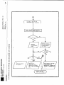
2.1 Procedure
for fault-finding
For fault
diagnosis
of the Control/machine
importance
to analyse
the behaviour
off the
a whole.
it is of
installation
prime
as
When fault
finding,
the solutions
should
be determined
using
the flowcharts
provided
in this
document.
Starting
from the
initial
apparent
fault,
the symptoms
of the fault
should
be
analyzed
in order
to pinpoint
the cause oft failure
(see
section
2.2).
In addition,
the HEIDENRAIN
TNC 150 Contouring
Control
includes
an extensive
integrated
supervision
system for the
avoidance
of entry/operator
faults
and for the recognition
and diagnosis
of technical
defects
on the machine/Control
system
(see section
2.2).
The BURN-IN Test Program
and the Test Program
TNC 150 can
be used as further
support
in fault
localizing
and in the
dynamic
testing
of the Control's
hardware
(see section
2.2.71.;
MANUAL TNC 150
2/2.1
DR. JOHANNES
D-8225
Telefon
Traunreut
(08669)
HEIDENHAIN
31.O.Telex
SERVICE
Page 4
Section
56831
Kundendienst
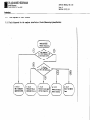
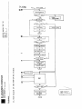
2.2
Flow
2.2.1
Fault
diagrams
diagnosis
for
fault
for
the
location
complete
installation
(Control/neasuring-Syst~/~chine)
MANUAL TNC 150
2.2/2.2.1
DR. JOHANNES
HEIDENHAIN
SERVICE
Page 5
Section
D-8225 Traunreut
Telefon (08669) 31-O. Telex 56831
Kundendienat
*
~2.2.2
use
of
the
integrated
supcrpision
system
.~?.he integrated
supervision
system
of the TNC 150 comprises
TNC hardware
and software.
It operates
continuously
whilst
the
Control
is switched
on, and recognizes
a major
proportion
of
faults
as well
as irregularities
in the Control
and the installation.
The
following
are
supervised:
.Programning
and operator
errors
Example
error
messages:
KEY NON-FUNCTIONAL
CIRCLE END POS. INCORRECT
ENTRY VALUE INCORRECT
.Control's
internal
electronics
Example
errcar
messages:
TNC OPERATING TEMP. EXCEEDED
EXCHANGE BUFFER BATTERY
TNC-ELECTRONICS
DEFECTIVE
.Measuring
system
and certain
machine
Example
error
messages:
X-MEASURING
SYSTEM DEFECTIVE
GROSS POSITIONING
ERROR
RELAY EXT. DC VOLTAGE MISSING
The Control
distinguishes
faults,
in that
faults
(eg. measuring
system
Control's
electronics).
machine
being
switched
functions
between
harmless
errors
and serious
are shown as flashing
displays
faults,
drive
faults
and faults
in:the
The occurrent*
of faults
leads
to the
off via the emergency
stop
contactor.
MANUAL TNC 150
2.2.2
DR. JOHANNES
D-5225
Telefon
Traunreut
108669)
HEIDENHAIN
31-O. Telex
SERVICE
Page 6
Section
56831
MANUAL TNC 150
2.2.2
Kundendienst
Error
messages
TNC 150
Error
messages
are not
and can be cleared
with
explained
in "Operating
and "Mounting
Instructions
Control-Machine
TNC 150
follow
the El
Manual
and
B/TNC
d by an emergency
stop
key.
Their
meanings
are
TNC 150 B/TNC 150 Q",
Interface
Circuit
150 Q” .
KEY NON-FUNCTIONAL
PROGRAM MEMORY EXCEEDED
SEARCH ADDRESS MISSING
TOOL DEF 0 NOT PERMITTED
PROGRAM NUMBER ON TAPE ALLOCATED
JUMP TO LABEL 0 NOT PERMITTED
ENTRY VALUE INCORRECT
CC-BLOCK MISSING
CIRCLE END POS. INCORRECT
TOOL DEF MISSING
TOOL CALL MISSING
LABEL NUMBER NOT ALLOCATED
EXCESSIVE
SUBPROGRAMMING
ANGLE REFERENCE MISSING
PLANE WRONGLY DEFINED
TOOL RADIUS TOO LARGE
ROUNDING RADIUS TOG LARGE
PATH OFFSET WRONGLY STARTED
PATH OFFSET WRONGLY ENDED
ROUNDING-OFF
UNDEFINED
ROUNDING-OFF
NOT PERMITTED
AXIS DOUBLE PROGRAMMED
WRONG RPM
NO EDITING
OF RUNNING PGM
RADIUS COMP. UNDEFINED
LIMIT
SWITCH X+
LIMIT
SWITCH XLIMIT
SWITCH Y+
LIMIT
SWITCH Y-
LIMIT
SWITCH AXIS Z+
LIMIT
SWITCH AXIS ZLIMIT
SWITCH AXIS 4+
LIMIT
SWITCH AXIS 4EXCHANGE BUFFER BATTERY
TRANSFERRED
DATA INCORRECT
ME: CASSETTE MISSING
ME: CASSETTE LOCKED
ME: WRONG MODE SELECTED
ME: WRONG PROGRAM DATA
ME: CASSETTE EMPTY
ME: PROGRAM INCOMPLETE
ME: TAPEEND
WRONG PROGRAM DATA
MACHINE PAPAMETER INCOMPLETE
EXT. IN-/OUTPUT
NOT READY
MIRROR IMAGE ON TOOL AXIS
WRONG AXIS PROGBD
WRONG SIGN PROGRAMMED
SPINDLE
ROTATES MISSING
SLOT WIDTH TOO LARGE
CYCLE INCOMPLETE
SELECTED BLOCK NOT ADDRESSED
PROGRAM START UNDEFINED
POSITIONING
ERROR
EMERGENCY STOP
ARITHMETICAL
ERROR
OPERATION PARAMETERS ERASED
3D-INTERPOLATION
NOT PERMITTED
FURTHER PROGRAM ENTRY IMPOSSIBLE
PROGRAM NUMBER UNAVAILABLE
PROGRAM NUMBER ALLOCATED
LABEL NUMBER ALLOCATED
TOOL NUMBER ALLOCATED
CONTROL VOLTAGE FOR RELAYS MISSING
POWER INTERRUPTED
DR. JOHANNES
D-8225Traunreut
Telefon (08669)
HEIDENHAIN
31.O.Telex
SERVICE
Page 7
Section
56831
MANUAL TNC 150
2.2.2
Kundendienst
Error
message
"EXCHANGE
BUFFER
BATTERY"
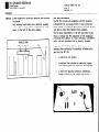
If the dialogue
display
indicates
"EXCHANGE BUFFER BATTERY";
new batteries
must be inserted
(discharged
batteries
support
the program
contents
for at least
1 week).
The buffer
battery
compartment
is located
beneath
the screw
cover
in the lower
left-hand
corner
of the operating
panel
(see section
C).
When exchanging
the batteries,
special
cars
should
be taken
when inserting,
that
the polarity
is correct
(POS-pole
of
battery
outwards).
The batteries
to be used have IEC designation
"LR 6" and must be of the leak-proof
type.
We
especially
recommend
the use of VARTA Alkaline
batteries
type
"4006".
With
discharged
(or missing)
buffer
batteries,
the memory for
the machine
parameters
and for the userprogram
will
be supported
as long
as the mains
remains
switched
on. Continued
operation
is still
possible
but
the memory contents
will
become erased
in the event
of a
mains
power
failure.
Please
note that
the TNC has to be
switched
on when exchanging
the buffer
batteries.
If a mains
power
failure
occurs
during
a battery
change
(discharged
or
missing
batteries),
new entry
of the machine
parameters
and
user
program
is necessary.
-Flashing
fault
messages
Important
functions
of the TNC 150 Control
are
supervised
through
self
diagnostics
(electronic
sections
such as wP, EPROM, RAN, positioning
system,
transducer
system
etc.)
If a fault
is detected,
a flashing
plain
language
fault
message
will
appear
in the dialogue
display and is
followed
by the opening
of the emergency-stop
contact.
This
condition
can be reset
by switching-off
the Control,
eliminating
the fault
and then switching
the Control
on
again.
.Flashing
AXIS
fault
X/Y/Z/4
EMERGENCY
messages
MEAS.
POINT
POWER OFF,
EMERGENCY
THEN
ON AGAIN
STOP PLC
GROSS POSITIONING
TNC OPERATING
ERROR IN
SYSTEM DEFECTIVE
STOP DEFECTIVE
WRONG REFERENCE
SWITCH
TNC 150
ERROR A/B
TEMP.
EXCEEDED
PLC PROGRAM A...Q
TNC ELECTRONICS
DEFECTIVE
CHECK SUM ERROR XXOO...XXFF
O...3/A...K
DR. JOHANNES
D-8225
Telefon
haunreut
(08669)
HEIDENHAIN
31-O. Telex
SERVICE
Page 8
Section
56831
MANUAL TNC 150
2.2.2
Kundendienst
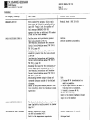
Fault
descriptions
VDU Display
TNC 150
Fault
(flashing)
X-MEASURING
SYSTEM DEFECTIVE
Y-MEASURING
SYSTEM DEFECTIVE
Z-MEASURING
SYSTEM DEFECTIVE
AXIS 4 MEAS. SYSTEM DEFECTIVE
RELAY
EXT.
EMERGENCY
DC VOLTAGE
STOP DEFECTIVE
WRONG REFERENCE
SWITCH
ON
AGAIN
MISSING
POINT
POWER OFF,
THEN
Possible
cause
.Measuring
system
not connected
.C&le
damaged
.Glass
scale
dirty
or damaged
.Scanning
head damaged
.Measuring
system
supervision
Measuring
damaged
Analogue
fault
location
system
Board
.Machine
voltage
(+24V)
missing
(for
checking
routine,
see Mounting
Instructions
and Interface
Circuit
Control-Machine
manual
TNC 150 B/
TNC 150 Q page 19 and 20)
.Supervision
circuit
defective
PLC I/O Board
PLC Interface
Board
SE Board
Terminal
Board
.Fault
in the emergency
stop
circuit
of the machine
(for
checking
routine
see Mounting
Instructions
and
Interface
Circuit
Control-Machine
manual
TNC 150 B/TNC 150 Q page 19/20)
Defect
in Control's
internal
Emergency
Stop supervision
Analogue
Board
PIC I/O Board
PLC Interface
Boaid
SE Board
Teminal
Board
.Traversed-over
reference
point
lies
outside
the reference
point
end-position
(also
see Mounting
Instructions
and Interface
Circuit
Control
Machine
TNC 150 B/TNC 150 Q, pg.20.21.22
.Defect
in Control/machine
interface
kchine
(cams/switches
"reference
end position"
pulse
inhibit")
Changing
of machine
14,15,60,72,90,170
parameters
12,13,
during
operation
PLC I/O Board
PLC Interface
Board
SE Board
Terminal
Board
(TNC
(TNC
(TNC
(TNC
150
150
150
150
P/Q)
P/Q)
A/B)
A/B)
ONC 150 P/Q)
(TNC 150 P/Q)
(TNC 150 A/B)
U-NC 150 A/B)
or
(TNC
(TNC
VTNC
YlYNC
150
150
150
150
"&&fere&
P/Q)
P/Q)
A/B)
A/B)
DR. JOHANNES
HEIDENHAIN
SERVICE MANUAL TNC 150
Page 9
Section 2.2.2
D-8225 Traunreut
T&ion (08669) 31-O. Telex 56831
Kundendienst
VDU Display
(flashing)
EMERGENCY-STOPPC
GROSS POSITIONING ERROR A
Fault
cause
With standard PLC program, faulty reply
from output A6 ("Lock for spindle on") to
input E20 ("reply:
Lock for spindle on")
Fault message EMERGENCY-STOPPLC
appears only when no additional
PLC marker
is set for the fault message
.Trailing
error with positioning
greater
than value entered in MP 174.
(see Mounting Instructions
and Interface
Circuit
Control-Machine
manual TNC 150 B/
TNC 150 Q page 45)
.Deviation
from the intended position
at
standstill
greater than the value entered
in MP 169
(see Mounting Instructions
and Interface
Circuit
Control-Machine
manual TNC 150 P/
TNC 150 Q, page 40)
.Exceeding the range for the continuous position
supervision
determined by MP 57.
(see Mounting Instructions
and Interface
Circuit
Control-Machine
manual TNC 150 B/
TNC
150
Q,
page
TNC-OPERATING TEMP. EXCEEDED
fault
Terminal
Board
location
(TNC 150 A/B)
.Machine
.Machine parameter
programming
43)
.Relationship
between output voltage
and
traversed
distance outside of the defined
tolerance.
.Defect in the pulse counting section (Control circuitry)
after the transduce+ signal
supervision
GROSS POSITIONING ERROR B
Possible
The Control-calculated
analogue
tage (implied by trailing
error)
than 10 V
Aid:
1. Program MP 54 (acceleration)
as
small as possible.
2. Adjust rapid travers
(as small a
trailing
error as possible).
3. Gradually
increase MP 54.
If this does not help:
fault in the Control hardware (closed
loop) or in the machine
output volis greater
.Ambient temperature
inside
the TNC has exceeded +65OC
.Fault in the temperature
supervision
Ambient temperature
Analogue
Board
of Control
P!!
DR. JOHANNES
D-8225
Telefon
-
Traunreut
(08669)
31-O. Telex
HEIDENHAIN
SERVICE MANUAL TNC 150
Page 10
Section
2.2.2
56831
Kundendienst
VDU Display
Fault
(flashing)
TNC-ELECTRONICS
DEFECTIVE
0
t
1
2
3
A
B
C
D
E
F
G
H
I
J
K
* CRC = Cyclic
** MID = Macro
Redundancy
Instruction
cause
False
CRC CHECK-SUM* of machine-referred
data without machine
parameters.
(Baud rate,
limitation,
preset
etc)
False CRC CHECK-SUM*
(machine
parameters)
False CRC CHECK-SUM (user memory)
Integrated
Test Program
execution
incomplete
Software
error
Main Processor
Software
error
CLP Processor
MID
interrupt**
CLP Processor
CLP Processor
instruction
stack overflow
False
instruction:
Main Processor-CLP
Processor
False
instruction
(display
mode):
Main Processor
-cLP
Processo+
CLP Processor
RAM (only with TNC 150 B/Q)
Overflow
interrupt
MID interrupt
Main
Processor
(only with TNC 150
B/Q)
Equipped
with incorrect
language
version
(only
with TNC 150 B/Q)
. ..FFFF Main Processor
(only with 'I'NC 150
RAM&M0
B/Q)
Check
Detection
Possible
Main
fault
*ocation
Processor/Memory
Board
Memory/Main
Processor
Board
Memory/Main
Processor
Board
Main
Processor/Memory
Board
Main Processor
Board
CLP Processor
Board
CLP Processor/Main
Processor
CLP Processor
Board
CLP Processor/Main
Processor
CLP Processor/Main
CLP Processor
Main Processor
Main Processor
Processor
Board
Board
Board
Main
Processor
Board
Main
Processor
Board
Board
Board
Board
DR. JOHANNES
D-8225
T&fan
Traunreut
(08669)
31-O. Telex
HEIDENHAIN
SERVICE MANUAL TNC 150
Page 11
Section
2.2.2
56831
Kundendienst
VDU Display
CHECK-SUM
(flashing)
ERROR
Fault
Possible
cause
fault
location
xx00
CRC CHECK-SUM error
with
EPROM 4
XX = correct
CHECK-SUM value
00 = code for
faulty
EPROMs
Main
Processor
Board
xx02
CRC CHECK-SUM
I,
11
II
xx04
error
II
with
EPROM 5
Main
Processor
Board
with
EPROM 6,7,8
Main
Processor
Board
XXOA
1,
11
II
11
with
EPROM 3
Main
Processor
Board
(PLC program)
XXOB
1,
II
,1
II
with
EPROM 9
Main
Processor
Board
(PLC dialogue)
xxoc
II
II
11
II
with
EPROM
Main
Processor
Board
I,
II
II
II
xx10
(EPROM B,C,D,E
with
A
with
EPROM B,C,D
TNC 150 A/P)
Menu~ry
Board
XX16
CRC CHECK-SUM error
with
(not with
TNC 150 A/P)
EPROM E
Memory
Board
XX18
CRC CHECK-SUM error
with
(not with
TNC 150 A/P)
EPROM F
Memory
Board
xx20
CRC CHECK-SUM
error
EPROM 2
CLP Processor
Board
xx21
CRC CHECK-SUM
CLP Processor
the operating
error
in RAM area on the
Board
in which
a part
of
program
is stored
CLP Processor
Board
XXFF
CRC CHECK-SUM error
PLC Marker
2815 is
with
with
set
PLC-P.AM
Main
Processor
Board
DR. JOHANNES
D-8225
Teiefon
Traunreut
(08669)
31-O.Telen
HEIDENHAIN
SERVICE MANUAL TNC 150
Page 12
Section
2.2.2
56831
Kundendienst
CRT display
Fault
(flashing)
ERROR IN PLC PROGRAM . . . .
Possible
origin
Fault
with
Description
safety-related
marker
manual
TNC 150 B/TNC
fault
location
(see PLC150 Q pages
36 . ..40)
A
PIG
start
Key
Error
with
B
Rapid
traverse
C
Direction
D
Feed
E
Start
PLC positioning
X-axis
F
Start
PLC positioning
Y-axis
G
Start
PLC positioning
Z-axis
H
Start
PIG positioning
IV-axis
I
Direction
key
X+
J
Direction
key
X-
K
Direction
key
Y+
L
Direction
key
Y-
M
Direction
key
Z+
N
Direction
key
Z-
0
Direction
key
IV+
P
Direction
key
IV-
Q
Undefined
macro
safety-related
latch
marker
key
key
release
cal led-up
via
PLC marker
Program,
Main
Processor
Board
Q
2
DR. JOHANNES
D-8225
HEIDENHAIN
SERVICE MANUAL TNC 150
Page 15
Section 2.2.4
Traunreut
Telefon KJ86691 31-O. Telex 56831
Kundendienst
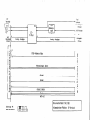
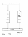
Power Supply Test
The voltages
(witlfboard
Data
are to be measured under
or load unit connected)
load
------,A
i.
I
I
DR. JOHANNES
D-8225Traunreut
Tel&n 108669)31-O. Telex
HEIDENHAIN
SERVICE MANUAL TNC 150
Paqe 18
Se&ion 2.2.7
56831
Kundendienst
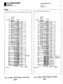
BURN-IN Test
In some cases, inspite
of these being definite
fault conditions on the Control,
error messages may not be displayed
on
the VDU. However, the Control's
electronics
can be tested
with the help of the BURN-IN Test Program or the Test Program
TNC 150.
These Test Programs are a means of dynamically
testing the
Control's
hardware and can be used not only for duration
testing but also for fault diagnosis.
These Test Programs are stored on digital
cassettes and can
be loaded into the Control via magnetic tape units ME 101 B/
102 B or ME 101 C/102 C (Program versions
212 902 05/
212 902 07). The Test Programs cannot be loaded into the
Control if the flashing
error message: "TNC ELECTRONICS
DEFECTIVE" is present on the VDU. In this case, the faulty
board must be determined by exchanging each board in turn
until the fault is eliminated.
However, before exchanging
any board, it is advisable
to check the output voltage
from the Power Supply Unit (see section 2.2.4).
2.2.1
To run the Test Programs it is necessary to have a set of
BURN-IN Test Adapters.
Depending on the type of Control,
(TNC with either
a
standard interface
or with an additional
PLC I/O Board) the
appropriate
adapters must be connected.
Control
Type
Test-Adapters
(see figure)
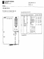
TNC 150 A/B/E/F
TNC 150 P/Q/V/W
PLC with bipolar
TNC 150 P/Q/V/W
PIG without bipolar
5.6,7,8,9
outputs
outputs
2,3,4,7,8,10
1,3,4,7,8,10
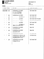
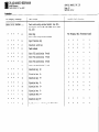
It is necessary to have the correct Test Programs for the
Type of Control and for the Control's
current
software
issue. The type of Control can be determined
from the
type-plate
or from the identification
number of the Control;
the software issue is determined from the NC Software number. The Id. No. of the Control and the NC
Software number can be found on the rear of the Control
on the type-plate.
DR. JOHANNES
HEIDENHAIN
SERVICE MANUAL TNC 150
Page 20
Section
2.2.1
D-8225 Traunreut
Telefon (086691 31-O. Telex 56831
Kundendienst
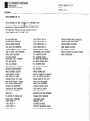
BURN-IN
Test
on the
Philips
Control
TY!F
TNC
Program
for
digital
NC Software
issue
222
129
99
from..,
..
222
129
99
..
222
129
..
222
150
TNC 150
A/E
B/F
..
Programs
and TNC 150 B/F
mini-casette
Control
Id. No.
Test
TNC 150 A/E
Test
dialogue
Test
Programs
on the
Philips
digital
for
TNC 150 P/V
and TNC 150 Q/W
mini-casette
Control
Type
Control
Id. No.
NC Software
issue
Test
dialogue
Test Prog.
Id. No.
TNC 150 P/V
222
128
99
from ....
..O 4
D
212 960
1A
..O 4
D
212
958
1A
from ....
..O 4
GB
212
959
IA
..
222
128
99
from ....
..O 4
GB
212
961
1A
99
from ....
..O 5
D
212 958
1B
..
222
128
99
from ....
..O 5
D
212 960
1B
129
99
from ....
..O 5
GB
212
959
1B
..
222
128
99
from ....
..O 5
GB
212 961
1B
225
012
99
from ....
..O 1
D
2x2
958
1C
225 013
99
from ....
..O 1
D
212 960
1C
225
012
99
from ....
..O 1
GB
212
959
1c
225
99
from ....
..O 1
GB
212
961
1C
..
TNC 150.Q/W
.
Test
TNC 150 B/F
Control
Type
Control
Id. No.
TNC 150 B/F
225
012
99
from ....
..O 1
225
012
99
from ....
..O 1
..
Test Prog.
Id. No.
BURN-IN
NC Software
issue
Programs
013
TNC 150 Q/W
Test Prog.
Id. No.
Control
TYPO
Control
Id. No.
NC Software
issue
D
227
879
ZY
TNC 150 Q/U
225
013 99
from...
. ..Ol
D
227
878
ZY
GB
227
881
ZY
225
013
from...
. ..Ol
GB
227
880
ZY
Test
dialogue
II
99
Test
dialogue
Test Prog.
Id. No.
DR. JOHANNES
D-6225
Telefon
Diag.
HEIDENHAIN
SERVICE MANUAL
Page 21
Section
2.2.7
Traunreut
(06669)
31-O. Telex
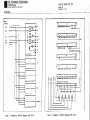
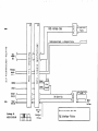
1 Schematic:
56831
BURN-IN
outputs)
PC-Adapter
(without
bipolar
Diag.
2 Schematic:
BURN-IN
outputs)
TNC 150
PC-Adapter
%.
(with
bipolar
DR. JOHANNES
D-8225
Telefon
HEIDENHAIN
Trsunreut
(08669)
31-O. Telex
SERVICE MANUAL TNC
Page 22
Section
2.2.7
56831
Kundendienst
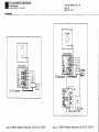
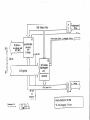
Diag.
3 Schematic:
BURN-IN
Adapter
TNC 150 P
Diag.
4 Schematic:
BURN-IN
Adapter
150
TNC 150 P
DR. JOHANNES
HEIDENHAIN
SERVICE MANUAL TNC 150
Paae 23
Se&ion
2.2.7
D-8225 Traunreut
Telefon (08669) 31-O. Telex 56831
,
Kundendienst
/I
c
-7
B
E:On”ector
,‘,f
x
,‘,I
w
,‘I3
I
,‘I‘
,!.I5
ov
*
,116
0”
Diag.
5 Schematic:
BURN-IN
Adapter
TNC 150 A
Diag.
6 Schematic:
BURN-IN
Adapter
TNC 150 A
DR. JOHANNES
D-8225
Telefon
Traunreut
(08669)
HEIDENHAIN
31-O. Telex
SERVICE
MANUAL TNC 150
Page 24
Section
2.2.7
56831
Kundendienst
SE-Output t 14 pin Amphenol phi 1
DTR
Rx
TxD
1
Diag.
7 V.24
connector
11-6
5-13
12 -14
I-
m
CTS
Rx0
-c8
(external
data
input
and
output
port)
Diag.
8 V.24
Test
Adapter
DR. JOHANNES
HEIDENHAIN
SERVICE
MANUAL TNC 150
Page 25
D-8225 Traunreut
Telefon (08669) 31-O. Telex 56831
Se&ion
2.2.7
Kundendienst
TNClSO
TNCISO A/B/E/F
P/Q/V/W
,I
TNClSOA
Bury
V.24 Test,
Diag
9:
BURN-IN
in
Adopter
Adapter
connections
for
TNC 150 A/B/E/F
Diag.
10:
BURN-IN
Adapter
connections
for
TNC 150 P/Q/V/W
DR. JOHANNES
HEIDENHAIN
SERVICE MANUAL TNC 150
Pase 26
Se&on
2.2.7
D-8225 Traunreut
Telefon (08669) 31-O. Telex 56831
Kundendienst
BURN-IN
1.
2.
Test
Program
for
the
complete
Connections
Depending
on the type of Control,
according
to diagram
9/10,
(page
tion
to the V.24 interface.
If
Control
below
indicates
to enter
the
Test
INSTRUCTIONS
are
KEYBOARD
connect
the test-adapters
251, except
for the connec-
Loading
the Test
Program
Connect
the ME 101 C/ME 102 C to the V.24 interface
of
insert
the program
cassette
and switch
on the
Control,
If the dialogue
"MACHINE PARAMETERS ERASED* is displayed
the VDU, the machine
parameters
have to be re-entered.
The table
necessary
no erras
the
mains.
on
detected,
the
question
TEST?
will
appear,
and all
the LEDs will
be extinguished.
NOW remove
the NE 101 C/ME 102 C and connect
the
Adapter
(Diag.8)
in its
place.
3.
the sequence
of operations
Program
into
memory:
v.24
Test
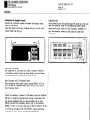
Keypad Test
The keypad
is tested
by pressing
the individual
keys of
each set of keys
in a certain
sequence
(top right
set of
20 keys,
top left
set of 25 keys,
bottom
right
set of 10
keys)
beginning
in each case with
the top left
key of each
field.
For each correct
depression
of a key,
a "*II will
be
displayed
on the VDU and the next
LED will
illuminate.
VDU DISPLAY
Press
the following
on ME B@@j
keys
POWER INTERRUPTION
Press
the
on TNC
keys
IPOWER INTERRUPTION
following
E-3
In the case of a faulty
key-code
or an incorrect
keying
sequence,
"KEYBOARD FAILURE"
will
be displayed,
and the
test
will
restart
after
about
1 sec.
If several
wrong
keys
are pressed
in quick
succession
the error
message
and cycle
restart
will
occur
ace
for each incorrect
key-push.
After
an error-free
keypad
test
the BU~RN-IN tw
iq.@e&
and the stored
error
condition
is cleared.
At the e&e
time,
'\i
the following
dialogue
is displayed:
CHANGE NM/INCH
IPOWER INTERRUPTION
CODE NUMBER
when the Test
Program
has been written
into
data is checked
using
the checksum
technique.
is detected,
axis
LEDs X,Y,Z,IV
will
flash,
following
dialogue
will
be displayed:
RE-ENTER
CHECK
PROGRAM XXXX
SUM ERROR
KEYBOARD IN ORDER
0, 1 OR 2 PC BOARDS?
The number of PLC I/O Boards
in use is then entered
by
pressing
the appropriate
key:
0,l
or 2. If no PLC I/O
Boards
are connected
the test
of the external
potentiometer
inputs
will
be skipped
(cf 5i).
the
RAM the
If a fault
and the
4.
Adjustement
of Spindle
Set the inte
alsets
the LED'rows
ITare used to :
pot.
respectively
are
and Override
Ig_o%df
adjusted
to
RPM Pots
WVDUis
100%.
m
wecw,
DR. JOHANNES
D-8225
T&ion
Traunreut
108669)
31-O. Telex
HEIDENHAIN
SERVICE MANUAL TNC 150
Page 27
Section 2.2.7
56831
Kundendienst
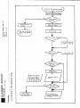
5. Cyclic Tests
Each test can be selected via the keyboard. If no fault
arises, the tests run in the following
sequence. With
each new test a different
LED will illuminate.
h)Test
KeyqI/O
ports
and monostable periods
(Main Processor:
2Cms)
(CLP Processor:
5ms)
-
a) Key El
Test internal
pots and battery voltage
The adjustment of the pots is correct at 100 + 2%
b) ,Key w
EPROMtest for Main Processor Board
The contents of the EPROMs are tested by the generation of checksums. The checksum for each addressing
range is displayed
in the form of a data word; the MSB
giving the sum actually
generated,
the LSB giving the
expected value. The address range displayed
refers to
the first
checksum that differs
from the expected
V?JUl%.
c) Key El
RAM test for Main Processor Board
Range: E!?%$Hto FFF9H
excluding working space: F@&%i to F@lFH
r=7
d) Keyljj
PAM test for Menwrv Board
Range: FFFFFH to F@#@H
e) Key a
RAM test for PLC
Range : E'@&&i to FFFEH, addressed
-
f) KeY151
Static RAM test for CLP Prcessor
Range: D@#JH to FFFFH
-
Test PLC instruction
decoder
via
Key
la]
Test ext. pot. inputs, analogue outputs,
and outputs
Al6 - A20.
Five external
relays,
driven from outputs Al6 - A20, are
used to connect analogue outputs X,Y,Z,IV,S
respectively
to the ext. pot. input (see diag. 4/6, page 22/23). The
test is made at three different
voltages:
20&N,
j)
sv,
9,5v
Key f-?-i
Test V.24 interface
k) Key a
Test supervision
1) Key cly
Test reference-pulse
mlKey
q
Test transducer/EXE
CPU
board
and accumulator
i)
flip-flop
circuit
input,
inputs
start/stop
flip-flop
DR. JOHANNES
D-8225
T&for.
Traunreut
(08669)
HEIDENHAIN
31.0,Telex
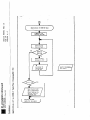
6. Fault Recognition
If a fault occurs, it will be displayed on the VDU. The
test cycle will be interrupted
and the BURN-IN Time stops.
In the event of a fault in either the override
pot. or the
IFI
QIIB
o=la Ei
!d. In the e+ent of a
for the battery voltage,
the
In all other cases, all
Each test can be restarted
by pressing the appropriate
kei. Any fault message will remain memorized and can be
recalled
by pressing theH
key, followed
by the@ key.
By means of the
key t&e fault message can be cleared
and the test cycle restarted.
If the CLP Processor recognizes a fault during execution
of the main program, the error message
q
CLP PROCESSORFAULT: XXXX
will be displayed.
The program can then only be restarted
by switching
the mains supply off and on again.
Possible
Code
0#8
&@A
@@i@
0@@
20xXx
21xX
Error
SERVICE MANUAL TNC 150
Page 28
Section 2.2.7
56831
Codes (XxXx):
Meaning
Incorrect
OP-code
Incorrect
command
Incorrect
display mode
Operating temp. too high
EPROMCRC-sum error
RAM CRC-sum error
I. Stoppi
If thewill belb
message
Test will
if it is
will be
displayed
the Program, Returning
to the Control Program.
key is pressed, the dialogue PRESS NOENT KEY
displayed
following
the memory test. If this
is then acknowledged with,the
key, the BURN-IN
start again from the beginning.
Alternatively,
acknowledged with the
key, the Test Program
erased and the dialogue POWERINTERRUPTED will be
on the VDU.
q
q
8. Restart Keyboard Test
The keyboard test can be restarted
Further procedure as per point 3.
by pressing
them
key.
9. Restart with "0.1 or 2 Boards" Request
By pressing them,key,
the request for the number of PLC
boards will be displayed.
Further procedure as per point 3.
10. Adjustment of Override
and Spindle
The nulling
routine
can be initiated
Further procedure as per point 4.
Pots.
with
them
key.
11. Interruption
of the BURN-IN Test.
The tests CM be interrupted
at any time arC.&&&ng off the:
mains supply. This, h-es,
does not apply to the Bfd~ry
,’
Board RAM tasttz,.~
The test run will start from the beginning when the mains
is switched on and them
key is pressed, provided
that no
errcx message is stored. If a keyboard test has not been
completed before an interruption
to the mains supply, the
keyboard test will be executed first
of all, when power is
restored.
DR. JOHANNES
D-8225
Teiefon
Traunreut
(08669)
31-O. Telex
HEIDENHAIN
SERVICE MANUAL TNC 150
Page 29
Section
2.2.7
56831
Kundendienst
Neither
BURN-IN
Time nor an errc~r message is lost
result
of an interruption
to the mains supply.
If
following
message is displayed
on the VDU:
as a
the
RE-ENTER PROGRAM XXXX
CHECK SUM ERROR
and the LEDs of the axis keys X,Y,Z,IV
are flashing,
a mains
interruption
has occurred
during
the Memory
RAM test,
and the Test Program
must be x-entered.
12.
Operation
without
VDU
After
completion
of the keyboard
test,
switched
off and the VDU disconnected.
the test
program
is as per point
11.
then
Board
the mains can be
The restarting
of
q-a
q
DR. JOHANNES
D-8225
T&ion
Traunreut
(086691
HEIDENHAIN
31-O. Telex
SERVICE MANUAL TNC 150
PacJe 31
Se&ion
2.2.7
56831
Kundendienst
Description
The Test
Program,
1.
Individual
of
the
Test
Program
TNC 150
Program
TNC 150 is an extension
of
and provides
the following
additional
Test
the
BURN-IN
functions:
Test
0 1 is
READ
5555
xxxx
A repetitive
will
then
IN Tests.
Run
K=Y tii!!
This
allows
any of the tests
contained
Test Program
to be run repetitively.
logue
will
appear
on the VDU:
If key
WRITE
within
the
The following
BURN-IN
dia-
pressed,
test
be run
the
can
once
dialogue
response
be aborted
using
again
in sequence,
will
be:
the :l!B
_~~ key.
The test
as per the BURN-
2. VDU Test
K=Y El
This
key
character
This
can
"INDIVIDUAL
TEST RUN"
ERROR INTERRUPT:
KN El
NO ERROR INTERRUPT:
KEY 1
0
permits
the entire
character
set
by character,
over
the whole
of
be started
and stopped
using
the
to be displayed,
the screen.
+/ key.
Ll
This
means that
if the 0 0 key is pressed
prior
to selecting
a test,
that
test
will
run repetitively
until
an error
upon detecting
an error,
the test
will
stop and an
occurs.
error
indicatio
'11 be given.
If instead,
the
1 key is pressed,
the occurrence
of an
error
with
cause r!
e test
to stop.
There
will
be no error
indication.
This
mode permits
cyclic
measurements.
Furthermore,
in the "ERROR INTERRUPT"
mode, the faulty
address
on the Main Processor
Board
or the Memory Board
can be written
to with
either
AAAA (1010 1010 etc)
or
555.5 (0101 0101 etc).
The following
dialogue
will
be displayed:
ERROR AT ADDRESS:
XXXX
WRITE TO FAULTY
SS
WITH AAAA:
KEY rr 0
WITH 5555:
KEY
El
If key Cl0 is pressed,
the dialogue
response
WRITE
READ
AAAA
xxxx
4.
Offset
Adjustment
K=Y I3
Adjust
for positive
16mV and 18mV. the
5..~@oard
As an
par&d
will
be:
of
the
DAC and
Analogue
Outputs
,.
and negative
polarity
polarity
can be reversed
symmetry
between
with
the +/ key.
cl
Exchange
aid in board
with
Where a fault
more extensive
replacement , each crrcm msssaga ~&%acccmto the likely
defective
board.
symptom cannot be Klatsd
to just one board,
dialogue is displayed.
a reference
DR. JOHANNES
D-8225
Telefon
HEIDENHAIN
SERVICE MANUAL TNC 150
Page 32
Section
3
Traunreut
(08669)
31.O.Telex
56831
KWldMldiinst
-.
~.i
tc
3. Exchange
Information
Note:
All inputs/outputs
from the
connected
to circuits
which
VDE S-73 S8.
Do not
disconnect
or connect
TNC 150 Control
can only
have voltages
confoming
plxigs~ under
be
to
power!
NC machines
also need protection
and installation
safety
as
required
for manually
operated
machines
(e.g.
EMERGENCY STOP).
Their
function
should
be checked
during
commissioning
of the
machine
and of a new Control
Before
noted
exchanging
or stored
a Control
on magnetic
the mc,~ine
tape.
pqameters
should
be
DR. JOHANNES
HEIDENHAIN
D-8225 Traunreut
Telefon
(086691
3.1 Ssdk&q
3. lil~~P*ooedure
1.
2.
3.
4.
5.
6.
7.
31.0,Telex
cultarl
SERVICE MANUAL TNC 150
Page 33
Section
3-l/3.1.1
56831
onits
for exchanging
the TW 150 A/B/E/F
Control.
Gain access to the rear of the Control.
Remove the mains supply.
Remove the connector
box cover-plate
from the rear of the
Control.
Mark the measuring
system plugs
(X,Y,Z,IV,
Electronic
Handwheel)
and remove them.
Disconnect
the VDU from the Control.
Disconnect
any external
d~ata devices.
Disconnect
coqector
strips
Jl-J6,
using
a screwdriver
to,'~
prise
the connectors
ap+rt
(Do not ~_nscrew in$v+al
wires),.
I
II
-
Handwheel
:1
prise
apart
screwdriver
with
a
8.
cable
Remove the faulty
Control
, removing
the fixing
screws if
not already
removed
in 1.
8; Install
the new Control
- check the voltage
selector
position.
10. Check the fuse-rating
(see type-plate).
11. Reconnect
alL cables
previously
removed.
12. Obtain
from the type-plate
the Control's
Id. Nq., NC and
PLC Software
Nos.,
and write
themin
the machine
handbook.
13. Refit
the conn&tor
box cover-plate.
11, Tuq
on the mains Voltage.
15. Reprogram
the machine
‘paramsters~.
‘..
16.
TNC is
now ready
to
use.
t
6,ll
DR. JOHANNES
HEIDENHAIN
D-8225 Traunreut
Telefon
(086691
31-O. Telex
SERVICE MANUAL TNC 150
Pase 34
Section 3.1.2
56831
Kundendienst
3.1.2 Procedure for exchanging the TNC 150 P/Q/V/W Control
1. Gain access to the rear of the Control.
2. Remove~the mains supply.
3. Remove the connector box cover-plate
from the *eax of
Control.
4. Mark the measuring system plug6 (X,Y,,Z,IV,
Electronic
Handwheel) and remove them.
5. Disconnect the VDU from the Control.
6. Disconnect any external
data devices.
7. Disconnect connector strips Jl-J6,
using a screwdriver
prise the conneci%rs apart (Do not,,unscrew individual
8. Remove the connecting cable to the PL 100 B/110 B from
Control.
prise ipart
screwdriver
with
a
the
to
wires).
the
\
cable
9. Remove the faulty Control,
removing the fixing
screws if
not already removed in 1.
10. Install
the new Control - check the voltage-selector
position.
11. Check the fuse-rating
(see type-plate).
12. Reconnect all cables previously
removed.
13..Obtain
from the type-plate
the Control's
Id. No., NC and
PLC Software Nos., and write them in the machine handbook.
14. Refit the connector box cover-plate.
15. turn on the mains voltage.
16. Reprogram the machine parameters.
17. TNC is now ready to use.
7,12
9
DR. JOHANNES
D-8225
Telefon
Traunreut
1086691
31-0,Telex
HEIDENHAIN
56631
Kundendienst
3.1.3
Pro&dure
for ewhanging
the PLC I/O Board
of the PL 100 B/110
1. Remove the fixing
screws of the heatsink cover-plate.
2. Remove the heatsink cover-plate.
3. Disconnect the TNC 150 connecting cable.
4. Disconnect connector strips Jl-J9,
using a screw driver
to prise the connector& apart:
(Do not unscrew individual
wires)
5..Remove
the voltage
supply (+24V and OV)
6. Remove the fixing
screws of the PL 100 B/110 B unit.
7. Install
the n&v unit following
the above procedure in,
reverse order.
SERVICE MANUAL TNC 150
Page 35
Section 3.1.3
-
DR. JOHANNES
D-8225Traunreut
Telefon (08669)
HEIDENHAIN
SERVICE MANUAL TNC 150
Page 36
Section
3.2
31-O. Telex 56831
Kundendienst
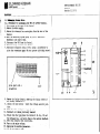
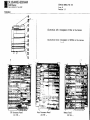
Board
Board Exchange
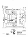
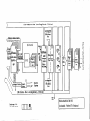
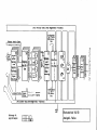
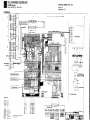
Board Arrangement
The TNC 150 consists
of threa
main sections:
1) The frontplate/Keypad
Board assembly;
2) The housing/Connector
Board assembly,
with
five
plug-in
boards,
namely:
.Memory Board
.Main Processor
Board
.CLP Processor
Board
.Analogue
Board
.either
SE Board TNC 150 A/B/E/F
or PLC Interface
Board TNC 150 P/Q/V/W
'~
3) The backplate,
Power Supply
Unit
and Terminal
Board
&xmbly.
arrangement
3.2
s
TNC 150 A/AR/B/BR
TNC 150 P/PR/Q/QR..
I
I
Ill-/
II
-~ .~
._
PLC I/O
TNC 150
Bodrd'
P/Q
389/223
(224
691)
Connector
Board'
(221 720)
Teminal
Board
(223
(228
806/223
164/228
(218
223)
Power
815)
166)
Supply
Board
‘. :
PLC Interface
TNC 150 P/Q
(222
B@ard,
044)
SE Board
TNC 150 A/B
(221
-.
744)
Analogue
(222
Board
5!J2/223
550):
CLP Proce~or
Board
(221
6781.:’
Main
Processor
b(222
509)
Memory
(222
Keypad
(219
in
Boa&
5061,
Board
..,
.‘”
*.
Board
441)
,_,
\
'
q
DR. JOHANNES
D-8225Traunreut
Telefon (08669)
31.0,Telex
HEIDENHAIN
SERVICE MANUAL TNC 150
Page 37
Section 3.2
56831
Kundendienst
Caution:
.Please observe MOS protection
measures when exchanging boards.
.Only exchange boards which have identical
assembly
numbers. The assembly number is impressed on every
board, to the left of the serial number.
Work area requirements
The TNC 150 contains sub-assemblies
with MOS elements.
Although MOS ICs are equipped with an input protection
diode network, to eliminate
the build-up
of static charges
care must be taken when handling
these elements.
The following
requirements
in the work area must be met:
Prior to working with MOS components or with assemblies
containing
MOS elements, all table coverings,
instruments,
tools, and work personnel must be properly
grounded.
A portable
necessary
servicing
"MOS-HANDLING-SET" for field
when exchanging the operating
the TWC 150:
service is
software and/or
1
a conductive
work surface
2
a wristband
that provides
an electrical
connection between person and conductive
work surface
3
a cable
between
that equalizes potential
conductive
work surface
differences
and ground
DR. JOHANNES
D-8225
Teiefon
Traunreut
(08669)
31-O. Telex
HEIDENHAIN
56831
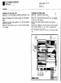
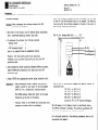
Exchengimg the pluggeble borrds
Unscrew the 5 mounting screws and remove the housing cover.
Removing the boards:
Press the board ejector keys outwards and pull out the individual board form the top.
Inserting
the boards:
The connectors of the boards are coded: incorrect insertion
is therefore avoided. Press the board firmly into the Connector Board using the ejector keys tilted
inwards.
Plain Processor and CLP Processor Board:
When exchanging these boards insert program EPROM's IC-Pl to
IC-P3 on the CLP Processor Board and IC-P4 to IC-PlO on the
Main Processor Board.
Board:
During the exchange or removal of the Memory Board the buffered
RAMwill no longer be supplied with voltage, which means that
the machine parameters and any user-programs will be lost!
Before inserting the new Memory Board, plug in the relevant
~PR~Ms, UC-P11 t0 IC-P14,,in the case of mc 150 A/E/P/V; IC-Pi1
to IC-P16 in the ceee of TNC 150 B/F/Q/W), paying particular
attention
to their correct location and orientation.
Memory
SERVICE MANUAL TNC 150
Page 38
Section 3.2
AnalogUi Board
Before removing the Analogue/Analcque TTL Br%ird'pull'dff
dnd
mark the connector plugs for the measuring system inputs/
square wave signal inputs and the electronic
handwheel in+
put. The connector sockets 0" the board are coded With
.':,
coding pins.
DR. JOHANNES
D-8225
Telefon
Traunreut
(08669)
31-O.Telex
HEIDENHAIN
SERVICE MANUAL TNC 150
Page 39
Section
3.2
56831
Exchanging
the Keypad Board:
.Re+ove
the 6 cross-head
fixing
screws
from the frontplate.
.Tilt
the frontplate
outwards.
.Ranove
connectors
J13 (feedrate-override
potentiometer)
and
J14 (spindle-override
potentiometer)
from the Connector
Board.
.F$emove the ribbon
cable
connector
P9 from the Keypad Board.
.Remve
the 7 cross-head
fixing
screws
which
secure
the Keypad Board
to the frontplate.
.Pull
off
the keypad
connectors,
Pl to P8 from the Keypad
Board.
.Remove
the Keypad
Board.
When rebuilding
toss
are firmly
the LE&
project
keypad
busing.
the assembly,
ensure
that
engaged
in their
respective
through
the corresponding
the
keypad
cmnecsockets,
and-t
bored
holes
i&j&&
,
DR. JOHANNES
D-82251raunreut
Telefon
(08669)
31-0,Telex
HEIDENHAIN
56831
.-,Exchanging the pmer Supply Unit:
.Remove gle 4 cross-head mour)ting scrnkl from the rear'of
the
Contrd
(2 s&revs are foulid in the con~+tor
box).
",
.Remove the backpl'&e with the Power Supply Unit and Terminal
goad.
.Disconnect the ribbon cable connector,
Pl, from the Connector
BC& (see diagram).
.Re,,,o"e the voltage
supply plug, P2, from the Connector Board
(see diagram).
SERVICE MANUAL TNC 150
Page 40
Section 3.2
nccban~~.tbr.~connsotor
B&d:
;
b
;i
.Remove the 7 cross-head fixing
screws.
,' :
"~.
.Disconnect
the battery
cdnnections
JJll)';‘
lr
_~
.Renwve the 2 cross-head
fixing .+crews of the V.24 co~e&$z
on the rear of the Control.
.Push the V-24 socket through its recess in the C&ol
:
housing.
'I
1'.
.Unsolder the conriectors to the VDU socket from the Connect&
Board (solder terminals
1 to 12). Note the colo~,i'of
~:I:_.:1% the
wire connected to each terminal.
.Pull the,Confiector
Board from the front of the Contrtil hour.~#.
ing.
DR. JOHANNES
D-8225 Traunreut
Telefon (08669) 31~0,Telex
HEIDENHAIN
SERVICE MANUAL TNC 150
Page 41
Se&ion
3.3
56831
Kundendienst
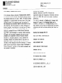
The operating
software
General
o NC software
0 PLC software
(IC-Pl...IC-P8,
(IC-P9)
The TNC 150 operating
software
is stored
in 13, 14 or
16 EPROMS, ~of type D2764,
depending
on the software
issue.
TNC 150 A: Control
with
o NC software
o PLC standard
TNC
TNC 150 B:
Control
with
o "B" NC software
and
o PLC standard
software
TNC 150 E:
as TNC 150 A,
however
with
export
TNC 150 P:
as TNC 150 B, however
with
"F"
TNC 150 ?:
Control
Software
3.3
-
TNC
150
Exchange
A/E/P/V:
IC-Pl...IC-P3
IC-PI...IC-PlO
IC-Pll..IC-P13
IC-Pll..IC-P14
150
(CLP Processor
(Main Processor
(Memory board)
(Memory board,
from software
board)
board)
or
issue
. . . . . . 05)
B/?/Q/W
- IC-Pll..IC-P16
Every operating
Software
No.
example:
Board,
(Memory
software
221
221
804
804
01
01
is
specified
with
"B"
with
with
software)
an 8 digit
complete
software
Id.
primary
software
Id.
update
software
index
No.
No.
TNC 150 Q: Control
TNC 150 V:
with
includes
IC-PlO...IC-P13/IC-Pl4/IC-P16)
example:
13,
14 or 16 programmed
EPROMs
is specified
with an 8 digit
221 410 CA
221
410
C
A
(IC-Pl...IC-P13/
Id. Non.
complete
Id. NO. of the progr.
EPROM
primary
Id. No. of the progr.
EPROM
position
on the board
(C = IC-P12,
HEXadecimal
counting
manner)
update
index
NC software
export
NC software
o NC software
and
o PLC standard
software
PLC custom software
or
o "B" NC software
and
o PLC standard
software
PLC custom software
or
as TNC 150 P, however
TNC 150 W: as TNC 150 Q, with
Each of the
IC-PlQ/IC-Pl6)
and
software
"F"
with
export
export
NC software
NC software
DR. JOHANNES
D-8225
T&ion
Traunreut
(08669)
HEIDENHAIN
31-O. Telex
SERVICE MANUAL TNC 150
Page 42
Section
3.3
56831
Kundendienst
The dialogue
language
of the TNC 150 A/E/P/V
is determined
by IC-P4
(located
on Main Processor
Board),
and IC-PlO
for the TNC 150 B/F/Q/W.
Each has its mm IC program
number:
Following
Software
GSZlIlaIl
English
French
Italian
Spanish
d~ialogues
are
available
for TNC lSOA/E/P/V:
(D)
(GB)
W
(I)
(E)
at
Software
Ge?XlaIl
English
French
Italian
Spanish
Swedish
Finnish
Dutch
Russian
this
time
for TNC 150B/F/Q/W:
(D)
(GB)
(F)
(I)
(E)
(S)
(SF)
(NL)
(SU)
The Id. Nos. of the other
programed
EPROMs are the ?.ame (for
a given
IC position)
in all
languages.
(prerequisite:
same
software
issue).
Exception:
IC-P9
(PLC software)
The standard
PLY program
(EPROM position
IC-P9)
can be replaced
with a custom PLC program
for
the TNC 150 P/Q/V/U.
(see chapter
SOFTWARE: PIG Reference
List)
The dot
in IC-Pl
matrix
for
(character
all VDU displayed
generator).
characters
is
contained
DR. JOHANNES
D-8225
Telefon
HEIDENHAIN
Traunreut
(08669)
31-O. Telex
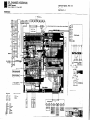
CLP Processor
221 678
SERVICE MANUAL
Page 43
Section
3.3
56831
Board
..
Main
Processor
222 509
Illustration
left:
Illustration
below:
Board
. .
Arrangement
Arrangement
boards
Memory
TNC 150
of
of
PCBs
in
the
Control
EPROMs on the
Board
222 506
..
various
DR. JOHANNES
HEIDENHAIN
SERVICE MANUAL TNC 150
Page 44
Section
3.3
D-8225 Traunreut
Telefon (08669) 31-O. Telex 56831
Kundendienst
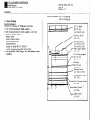
Software
- After
the software
exchange
has been concluded,
the
of the NC- and PLC-software
have to be changed.
The
tion
plate
for the software
numbers
is found on the
the Control
under the type-plate.
Exchange
Caution:
,
When exchanging
the
protection
procedures!
o The cover of the
the 5 cross-head
Control
mounting
o To exchange
the program,
- Memory Board
~- M&in Processor
Board
- CLP Processor
Board
have to be removed
from
Thereto,
outwards,
protection
software
observe
the
can be removed
after
screws (top side)
the
following
MOS
Id. Nos.
descriprear of
unscrewing
The
Id.
No.
always
ends
with
. . . . . . 99.
boards
2
3
4
the
assembled
lift
the board ejector
pull
out board
from
mat.
Control
keys and press
above and lay onto
MOS
o Push screwdriver
blade
carefully
between EPROM and socket,
remove EPROM with extraction
tool
and place
onto MOS
protection
mat.
o Insert
Important:
EPROM into
appropriate
- When exchanging
number
(second
EPROM Id. No..
socket
insertion
EPROMs, observe
the
to last digit
of the
hexadecimal
counting
- The EPROM package
direction
as the
- Visually
respective
using
check if
sockets
index must point
ICs on the board.
tool.
The Id.
converted
position
programmed
manner)
in
the
the EPROMs are contacting
after
an exchange.
same
No.
of the Control
from:
TNC 150 A
TNC 150 E
TNC 150 P
TNC 150 V
by use of
changes
to
to
to
to
"B"
TNC
TNC
TNC
TNC
or
only
150
150
150
150
"F"
B
F
Q
W
type
when a Control
is
NC Software.
their
The PAM memory of the Memory Board is unbuffered
during
the EPROM (software)
exchange.
The machine
parameters
and
any stored
user-program
are therefore
erased!
For continued
operation,
re-entered
into
memory.
the
machine
~parameters
have
to be
q
DR. JOHANNES
D-8225Traunreut
Telefon
108669)
31~0,Telex
HEIDENHAIN
SERVICE MANUAL TNC 150
Page 45
Section 3.4
56831
Kundendienst
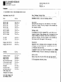
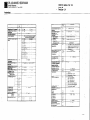
3.4 Replacement Parts, Loan/Exchange/Service
~~..
Replacement Parts TNC 150
Unit
TNC
TNC
TNC
TNC
TNC
TNC
TNC
TNC
150
150
150
150
150
150
150
150
A/E
B/F
P/V
Q/N
AR/ER
BR/FR
PR/VR
QR/WR
PL 100 B
PL 110 B
Display
Display
Unit
Unit
Id.
No.
222
225
222
225
224
226
224
226
129
012
128
013
413
472
414
474
----------
223 836 -223 216 -BE 111
BE 211
212 300 -222 674 --
Assembly
Id.
No.
Connector Board
Keypad Board
Memory Board
Main Processor Board
CLP Processor Board
PLC-Interface
Board
SE-Board
Analogue Board
Analogue Board TTL
Power Supply Unit
(backplate of housing
with Power Supply Unit
and Terminal Board)
221
219
222
222
221
222
221
222
223
720
441
506
509
678
044
744
502
550
----------
Units
Loan, Exchange, Service Units
In order to keep machine down-time as short as possible,
HEIDENHAIN offers
a loan and exchange service.
Loan units
Loan units are available
for the duration
of the repair,
time free of charge. The only charges to the customer aYe
.,
the'shipping
charges.
Exchange units
i.
An exchange unit can be requested for a unit that is returned for repair.
This exchange unit is equipped with,the
latest hardware and software issue and is externally
iti.~
excellent
condition.
The only charges to the customer +
this case are for the repair'of
his own unit.
,.;
Transaction
Requested loan or exchange units are shipped on the
of request,
or the following
day, provided
that the
is available
from our stock.
A cust&ner's
faulty unit should be returned
to DR.
HEIDENRAIN within 14 days of receiving
the exchange
:7
dat$
unif
JO&ES
une.
;'
s:
:i
Service units
Service.units
are new units which are ueed fo&.+~er+e
purposes and can bee obtained frotibR.'~Z&AN&~
~EIDENHAIN
at non-repeatable
discount prices.
DR. JOHANNES
D-8225
Telefon
Trsunreut
(08669)
HEIDENHAIN
31.O.Telex
SERVICE MANUAL TNC 150
Paae 46
Se&ion 4/4.1
56831
Kundendienst
4.
Additional
- Input/Output
facilities
system inputs, analog
Information
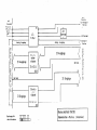
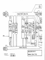
4.1 Block Diagram Description
General
The TNC 150 block diagram shows, in simplified
form, the internal functional
units of the control,
their relationship
to the
various boards, and their interconnections.
The graphic layout
of the diagram and the way it is included in single sheets.
- the representation
of any of the TRC 150 models (A/AR/P/PR),
- simplified
representation
of functional
processes
Numbers enclosed
functional
unit.
in dashes inform
+%&division
Functional
Board
Simplified
Description
about
of functional
Unit
the board and its
The functions
microprocessor
(e.g. keypad, screen, measuring
outputs,
LBDs, V.24 interfaces
etc.)
of the control
are divided
systems as follows:
1. "Main Processor System"
- Keyboard, LEDs
- User Program Interpreter
- Provision
of programming "environment"
- Generation
of PLC program addresses
* - Transfer
of input and output states between PLC Interface Board, SE Board and PLC RAM
* - Control of the V.24 interface
2. "CLP-Processor
System.
- Ascertainment
of instantaneous
- Interpolation
Calculations
- VDU Control
* - Demand Speed Values to DAC
unit
between the two
positions
of the TNC 155 (Block Diagram)
* Serial
-
Keypad Board (1)
Memory Board (2)
Main Processor Board (31
CLP Processor/Graphic
Board (4)~
Analogue Board/Analogue
Board TTL (5)
with SE Board (6) it corresponds to a A(E)-Type;
without SE Board, with PLC Interface
(6). however
with PLC I/O-Board(s),
it corresponds to a P(V)-Type
respectively,
PR(VR)-Type
- Power Supply Board (7)
- Terminal Board (8)
The functional
processes of the control are divided
two microprocessor
systems, each comprising:
- Microprocessor
(TMS 9995)
- Program Memory (EPROMS)
- Write-Read Memory (RAMS)
data transfer
Main Processor
via
CRU bus.
Unit
- Primarily
on the main processor board
- The operating
system software is held
or,
between
-30.1-30.3-30.3-2o-
IC-P4 (not mapped)
IC-P5...IC-PS
IC-PlO (dialogue
language)
Ic-P1l...Ic-P1S
and the memory board.
in EPROMs:
Main Proc. Board
Memory Board
DR. JOHANNES
D-8225
Telefon
Traunreut
(08669)
31-O. Telex
HEIDENHAIN
SERVICE MANUAL TNC 150
Page 47
Section 4.1
56831
Kundendienst
-
RAMS
-30.2on the main processor board can be accessed
either by the main processor -3O- or by the CLP processor
-4O-. The intended coordinates,
programmed feed, display
texts etc. can therefore
be transferred.
These RAMS also serve as register
file memory for the main
processor -3O-.
User programs, machine parameters,
and (under certain
circumstances) the PLC program are programmed in RAMS -20.1-.
The
- The 16-bit address bus is extended
mapper -31-.
to 20-bit
by a memory
- The keyboard controller
-32- has the task of driving
the
LEDs and scanning the kelpads -32.1- on the front plate.
- The main processor is connected with V.24 interface
-34Via a (serial)
CRU-bus. This interface
is used to exchange
data by means of a magnetic tape unit (ME) or, respectively, an external
processor.
- The PLC program contained in IC-P9 -33.1- is processed by the
-33- mounted discretely
on the main
"1-bit-PLC-processor"
processor board. The input and output states are stored in a
4k x 1 PLC-RAM -33.2-.
- I/O-Functions:
a) TNC 150/151/155 A-Versions:
24 galvanically
separated
inputs (EO to E23) -6O- and 24
floating
relay contact outputs
(A0 to A22 + emergency stop)
-61- on the SE Board. The inputs and outputs are protected
on the terminal
board (A version)
by special protective
resistances
5.lkohm -8O- and 47ohm -8O.l-.
Protective
resistances
should never be replaced with normal
resistances!
The Analoque outputs are led via LC-filter
-81- as protection against the oscillation
of analogue outputs.
b) TNC 150/151/155 E-Versions:
The inputs and outputs are loaded on external
PLC
I/O-board
(e.g. PL 1OOB or, respectively,
PL 100B)
which are driven by the main processor -3O- via the PIC
interface
board. The data is serially
transferred
via
the CRU-bus. All lines of this bus as well as the
required
addresses are galvanically
separated by the
optocouplers
-6O- and are converted
from the TTL level
(5V) to the MOS level
(12V) by means of a level converter
-61-. Thus a higher noise immunity is obtained.
Under the control
of CRU addresses 63 programmable inputs
(EO to E62) -E2- located on the PLC I/O board are multiplexed on CRUIN 1 line. If 2 PLC I/O boards are connected
the inputs from the 2nd board are multiplexed
on CRUIN 2.
On the PLC interface
board either CRUIN 1 or CRUIN 2 are
selected -64- and are led to the main processor via CRUIN.
The serial CRU OUT signal is converted
in 31 outputs via a
serial-parallel-converter
-El.l-.
The outputs (each having
its own current
supervision
-El-) are transferred
via line
drivers
to the machine interface.
- An overloaded
output only switches off during the period
of the overload.
- If the current supervision
detects overcurrent
no
emergency-stop
results
in the standard PLC program.
The input E63 is used to indicate
an overloaded
output to
the main processor -3O-.
PL 100B: 31 unipolar,
programmable outputs +
emergency-stop
protected
against overload.
PL 1lOB: 26 w-&polar,
programmable outputs + 5 bipolar
outputs and emergency stop protweed
against
overload.
On the PIG I/O board a 12V voltage is generated by an
external
24V supply. On the PIG intaface
board this 12V
voltage is transformed
in a 5V voltage
for its TTL modules.
DR. JOHANNES
D-5225
Telefon
HEIDENHAIN
SERVICE MANUAL TNC 150
Page 48
Traunraut
(08669)
31-O. Telex
56631
Section
4.1
Kundendienst
CLP Processor/Graphic
System:
- Primarily
on the CLP processor/graphic
- Operating
(Sk x 8).
system is contained
board.
in EPROM IC-P3 -40.1-
- The main task is the calculation
of the instantaneously
intended values of the analog output voltages
dependent on:
.the instantaneous
actual positions
.the programed
intended position
.the distance of the intended position
(influence
on deceleration
ramp)
.the programed
feed rate
.the fast traverse
rates determined per machine parameter
.the settings
of the override
and feed potentiometer
The calculating
speed requires
a wait-free
RAM -40.2-.
- The measuring system signals are processed on the analog
board. These signals are amplified
at first
-5O.l- and
then subdivided
-5O- by delaying
(phase shifted)
and
combining them differently.
The subdivided
0 degree,
90 degrees and RI signals are then led to the gate arrays
-42- of the CLP processor board. The gate arrays consist
of different
gates and counters whose direction
of the axis
movement and the number of pulses is calculated.
This
information
can then be scanned by CLP processor -4O- to
ascertain
the actual values of the axes.
- The symmetry, the on-to-off
ratio and the amplitude of the
system signals are constantly
controlled
by a supervision
circuit
-5O-.
- If the distance between the control
and measuring system is
nwre than ZOm, an EXE has to be interposed.
The measuring
signals are thus already amplified,
subdivided,
evaluated,
supervised
and converted
in TTL signals.
An "R" version of
the control
is used accordingly
(e.g. TNC 150 AR) equipped
with a combined EXE connection
for X-, Y-, and Z-axis and
an analog board TTL. The input amplifiers
and the wiring
for the signal subdivision
are replaced with line receivers
-5O- on this analog board whose outputs are directly
connected to the gate arrays -42- on the CLP processor board.
The supervision
signal of the EXE is also buffered
-SO- and
transferred
to the CLP processor board. The signals of the
handwheel are likewise processed -53- as on the "normal"
(sine) analog board.
- If instead of linear position
transducers
incremental
encoders are used to ascertain
actual values a reference
pulse
appears once per revolution.
Since only one reference
pulse
is to be evaluated
all other reference
pulses of the axes
X Y. Z IV are lnnlblted
on the analog board -5~. The
signal iines are connected with the analog board via the PLC
I/O board and the PI&! interface
board. The level conversion
MOS/TTL as well as the galvanic
decoupling
is carried
out
on the PLC interface
boards via -61- and -6O-.
DR. JOHANNES
HEIDENHAIN
SERVICE MANUAL TNC 150
Page 49
Section 4.1
O-8225 Traunreut
Tel&n (08669) 31-O. Telex 56831
Kundendienst
- The data of the CLP processor is transferred
to the analog
outputs via the serial CRU bus. The digital
output values
calculated
for all axes are multiplexed
on the CRU OUT line
and are converted
in a 12 bit parallel
format on the analog
board. These successive digital
values are then converted
in analog values (voltages)
by means of a DAC -52.1(digital-analog-converter).
These voltages
are compared with the
adjusted values of the override
and feed potentiometers
-52- and the results
are transmitted
to the CLP processor
via CRUIN. The output voltages
can thus be adapted to the
values adjusted by the override
or, respectively,
the feed
potentiometer.
The X-, Y-, Z-, IV- and S-analog values
generated shortly one after the other at the output of the
DAC are allocated
to the single axes by means of five
sample and hold circuits
-52.2-.
The five individual
analog voltages
are amplified
and buffered
subsequently
-52.3- and are led to the terminal
board.
- On the analog board the buffer
battery
(3,46V) and the
internal
temperature
(6S") of the control
are also supervised -51-. The supervision
signals are led to the CLP
processor via the CRUIN line.
- Two "watch dog" monoflops -51.1- are on the analog board.
These must be triggered
separately
once every 5ms by the
CLP processor -4O- and once every 2Oms by the main processor -3O-.
If the monoflops are not driven within Sms
or 2Oms (err&
state),
an emergency-stop
signal is
triggered.
- The drive of the screen is another important
task of the
TNC 150 CLP processor.
It only has to write the texts to
be displayed
into the CRT RAM -41-l-.
A special CRT controller
TMS 9937 -41- generates the necessary addresses
for the CRT RAM and the character
generator
IC-Pl -41.2so that the data are transferred
to the shift register
-41.3- in the right sequence. Thus signal can be inverted
by means of an exclusive-or-gate
-41.4- to generate an
inverse video display.
The video signal, the bright/dark
signal,
supply
the horizontal/vertical
are used to operate
sync. signals
the screen.
and
an
1lV
Power Supply Unit
- +5V are generated for the TTL modules via
verter
-7O-. The flyback regulator
-70.1coupled with the flow converter
generates
operation
amplifier.
the forward coninductively
+/-15V for the
- The +lZV supply voltage
for the V-24 interface
with the help of the +15V by menas of a linear
is generated
regulator
-70.2-.
- +llV are generated via the forward converter
-70.3- for
the TNC 150 (BE 111, BE 211) screen. The switch regulator
-70.01- and -70.31- readjust
the output voltage
load
controlled.
- The soft
current.
start
-71-
limits
the relatively
high
switch-on
- On the power supply board there is, moreover,
a voltage
supervision
-72- triggering
a reset signal if the power
supply is interrupted
or if the supply voltage
drops below
a predetermined
minimum level
(187V if set for 22OV operation) for a short time.
If U2 (+5V) exceeds if there is a failure
the overvoltage
recognition
-73- is immediately
effective
and causes the
overvoltage
protection
(thyristor)
-73.1- to connect
through.
Thus Ul is short-circuited
coming directly
from
the power supply transformer
-74- via the rectifier
-75-.
A greater damage at the subsequent electronics
is thus
inhibited
by means of this protective
measure.
DR. JOHANNES
D-8225
Telefon
Traunreut
108669)
HEIDENHAIN
31-O. Telex
SERVICE MANUAL TNC 150
Page 50
Section
4.1
56831
Kundendienst
4.2
Block
Block
Diagram
TNC 150
Diagram
Arrangement
PI&I/O-Board
power
Supply
Terminal
Board
(P-Version)
Terminal
Board
(A-Version)
PLC Interface
Board
SE-I/O-Board
Main Processor
Board
CLP Processor
Board
Analog
Board
Wl!L-Input)
Analog
Board
Memory
Board
Drawing
4820
4820
4820
4820
4820
4820
4820
4820
4820
4820
4820
4820
Nmbe~r
EKD
EKD
EKD
EKD
EKD
EKD
EKD
EKD
EKD
EW
EKD
EKD
1606500
1607200
1607600
1607100
1607000
1606700
1606800
1606900
1607500
1607300
1607400
1606600
Page
51
52
53
54
55
56
57
58
59
60
61
62
OOER
,
-
SEEin /Ausgang
Plotine
ODER
AnalogteilPlatine
1
tecker-
Zeichnungs
- Nr.:
4820 E KD 16063 00
Platine
9
Anordnung
und Platinen
der Blbckschaltbilder
fiir TNC 150
I
I
CRU -Adress
“0” PlC Interfote - Ploline
-Bus
zu PLC - Inlcrfocr-
Plotine
I
CRUIN 2 vca der 2~PLC-:
CRUIN 1 zu
PLC-Interfore-Plotine
zu Z.PUI-Ein/Ausa.-Plotinc
-I/ I
‘/I
CRUOUT. CRUCLtt
_
Li
“0” PU-lnterfoce-Plotlne
Reset
NOT AUS zu 2.PLC.
Ein /Ausg.-Plotme
NOT AUS “on
fu-InkforePlotinc
I
I
Blockscholtbild
ZcichnunqsNr.:
4620 E KO 16059 00
TNC 150
iExternVLC-EinlAusgong-Platine
I,.,:.,:::
V
II’
11,
V
10
,
15,
--------
”
“2
B.5
tmit
“3
imit
L--------------------
v
Tirfpaflfiltert
r-
ZeithnunqsNr.:
LB20 E KD16064WJ
V
Tirfpoftfiltert
I
0.
11 v
NW bei TNC 151
i
I
I’otiSchleller
I zur Analaqteil.
Plutlne,
81
rcgler
LC Filter
Analog
- Ausqiinge
-
-=G +lSV
t
r
<
Anolog
- Bus
Referenzimpuls
- Sperre
CRUIN
2
CRUIN
1
CRUOUT. CRUCLK
Rcsc t
L.
NOT AUS
1
Zeichnungs
Blockschaltbild
- Nr.:
4620 E KO 16057 W
Klemmleisten-Platine
I
ov
Anol~trilPlotme
- AurgSnge
r--!
CRU -Adress
tletztcil
TNC 150
(P-Version)
Poli
Scllleiler
lzur AdogleilPlatlnet
‘I
ext.
Vorschub
.
81 -
-
I
I
ov
.lZV
LC Analog
- Ausgiinqe
Analog
- Ausgiinge
23 Ausgiinge
,
. NOT AUS
1
c
9
23 Eingiinge
23 Eingiinge
$
Schutzwider stiinde
>
23x5,1
L-
kfl
8C
Blockscholt
Zctchnungs-Nr.:
6820 L KDlb058
K.lemmleisten
00
bild
TNC 150
- Plotine’~
(A-Version)
z
.
CRU-Adress-Bus
Refrrenzimpulr-Sprrre
- zu Anologtril-Plotine
/
I
>
A
/
\
CRIJIN ‘2
CRUIN 1-
0
c
zu/ml
/
Reset
,y
NOT AUS -
Zeithnurqr
- Nr.:
1820 E KO 16054&J
CRU-Ootrn-Bus
\
I
I
NOI AUS
“0”
Anologteil
Plotine
Blockscholtbild
PLC-Interface
TNC 150
-Plotine
nauptrechner
-
I
I!iI
CRU -Adress
-2
II
t/+
Reset
1
Rrl
61
21, Relais Ausgiinge
und
NOT AUS
:a
N .$
9
a
I
El
SerienlParallelUmsetzer
und
24 Relais
-NOT
AUS
NOT AUS
60)
.!2
aI
24 Eingtinge
(Optokopplerl
und
ParallellSerien-
2
(Y
$22
5
“cm HauptrechnerPlotine
-Bus
24’ Eingizinge
/
-
-zulvan
HauptrechnerPlotine
fi5
=:
NOT AUS
“on
Anolaglci
IPlotine
ZeithnungsNr.:
4f120 L KO 16055 00
Ill
2
I
Blockschaltbild
TNC 150
SE-Ein /Ausgang
- Plotine
c
_
I” SE /PLCInlerlwPyle
>
Z”rn trternm
computer.
1 tloqnr”~andrinheit.
USY.
.
Erweiterter
(20bit)-Adress-
Bus
rRAM
“Haupt rechner”
K-b3
K-P10
5x,
8kxti
CPU
IMS 9995
lnicht
mopborl
WOkplZ
iem. RAM
n Adrerr
Burt
f”Dialoq5 rache
I
Standard
-c,
I
u
CRU-Doten-Bus
zu SEIPU-Interfoce-Plotinr
r
EPROM
K-P5
I
-0aten
I
-Bus
ICRUIN. CAUOUT. CRUCLKI
I
32.1
Zcichnunqs
-Nr.:
4820EK01605600
FIIUn,
J 1-----_System
PU-Rechner-
Standard
116 bit 1 - Adress - Bus
I
40.1
FROM
IC -P3
:I
Videoontrolle
32kx6
Stodadl
Expwt
Reset
TMS
)931 Nl
I
rII
llll%lll
l-l
I Zeichen-
I
7
Standard
Zelchnunqs - NC:
1LI20EK01606200
EPROM
IC-P19
8k x 8
- Daten - BUS
r
tlR-Signal
CRU-Adress-
Bus’ Avon Regelkreis
van Hauptrcthner-Plntine
CRU-Adresr Bus
Referenz - lmwls - Swrre
van SE/PlLlnlerf.-Ploline
-PlatineI
11
-
II I
(Externl
I
I
I:
51’
II I,
‘51.1
I-
Etatterie
1!OrnS5
und
1lempe- -’ hoflop %f graturuber ‘rJachunC
@$
cq
G
/
53
1 0.
) 90.
‘~-Y&!t~~ -
Hondrodlingkige
Bus
V
(/
CRU-Daten-Bus
tvon Regelkreis
-Platine)
N
NOT
AUS
Zeithnungs - Nr.:
4820 E KO 16060 00
r-
3F
ext.
.~I
Analogteil -Platine(TTL-Eingiirge)
CRU -Adress
-Bus
ivon Regelkreis -Platinet
.-r”
t
tOms Smr
lono- I tlom
flop 1 flop
I
\>
\
CRU-Daten-Bustvon
Regelkreis -Platinet
nA
I
Zeithnungs-Nr.:
la20 EKO 1606100
d
EPROM
RAM
IC-Pll
( Anwender
1280 Siitze
IC 418
8x8kx
8
14x 2k x 8
CRU-Oaten
- Bus
Blockschaltbild
Zeithnungs
-Nr.:
4820 EKU1605300
Speicher - Platine
TNC 150
DR. JOHANNES
D-8225
Telefon
Traunreut
108669)
31-O. Telex
HEIDENHAIN
SERVICE MANUAL
Page 63
Section
4.3
56631
Kundendienst
4.3
Wiring
Diagrams
Wiring
Diagram
TNC 150 A/B/E/F
Drawing
No.
222
655
P.
64
Wiring
Diagram
TNC 150 AR/BR/ER/FR
Drawing
NO.
224
405
P.
65
Wiring
Diagram
TNC 150 P/Q/V/W
Drawing
No.
222
583
P.
66
Wiring
Diagram
TNC 150 PR/QR/VR/WR
Drawing
No.
224
406
P.
67
TNC 150
DR. JOHANNES
D-8225
Telefon
HEIDENHAIN
Traunreut
(08669)
31-O.
Telex
56831
SERVICE MANUAL TNC 150
Page 64
Section
Kundendianst
,
4.3
DR. JOHANNES
D-8225
Telefon
Kun
dienst
Traunreut
iO8669)
31-O. Telex
HEIDENHAIN
56837
SERVICE MANUAL
Page 65
Section
4.3
TNC 150
DR. JOHANNES
D-8225
Telefon
Kundendienst
V,.- ”
:::
1s
::s
..”
::z
::=
::it
Traunreut
(08669)
31-O. Telex
HEIDENHAIN
5683,
SERVICE MANUAL !PNC 150
Page 66
Section
4.3
DR. JOHANNES
D-8225
Telefon
Kundendit
x
Y
z
P
Traunreut
1086691
31-O. Telex
HEIDENHAIN
56831
SERVICE MANUAL
Page 67
Section
4.3
TNC 150
DR. JOHANNES
D-8225
Telefon
HEIDENHAIN
Traunreut
(08669)
31~0.Telex
56831
SERVICE MANUAL TNC 150
Page 68
DR. JOHANNES
D-8225Traunreut
T&ion
(08669)
31-O. Telex
HEIDENHAIN
56831
,
Kundendienst
SERVICE MANUAL TNC 1%
.Paga 69
$kctfon
4.4
DR. JOHANNES
D-8225
Telefon
Kundendienst
Traunreut
108669)
31-O. Telex
HEIDENHAIN
56831
SERVICE MANUAL TNC! 150
Page 70
Section
4.4