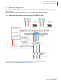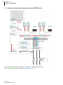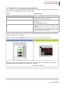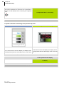
1
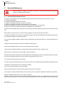
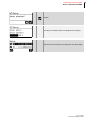
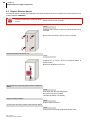
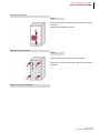
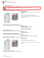
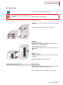
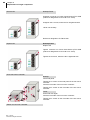
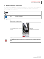
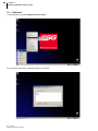
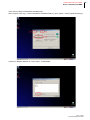
Service Manual Hot Runner Controller Rev. 1.00.05 10/2014 Translation of original service manual 1 PSG Plastic Service GmbH Service manual profiTEMP 1 Typographical Conventions 3 1.1 Additional and continuative documents 3 2 Security References 4 2.1 Security References for User 4 2.1.1 Intended use 2.1.2 Maintenance 5 5 2.2 Warranty Conditions 2.3 Transport and Storage 5 6 2.3.1 Transport 2.3.2 Storage 6 6 3 System Configuration 7 3.1 Schematic presentation standard series profiTEMP Desktop 3.2 Schematic presentation standard series profiTEMP Tower 3.3 Front side hot runner controller - Display and Operation 3.4 Rear side hot runner controller - Connections 7 8 9 11 3.4.1 profiTEMP Adapter COM 3.4.1.1 Interface RS485 XS1 3.4.1.2 Interface CAN XS2 3.4.1.3 Digital in- / - outputs XM3 3.4.2 profiTEMP Adapter ETH 3.4.3 Alarm Output (Signal Plug XM1) 3.4.4 Control fuse 3.4.5 Sensor inputs and power outputs (Plug XA) 3.4.6 Power Supply 12 12 12 13 14 15 15 16 16 3.5 Left side hot runner controller - power supply, power out- & sensor inputs 3.5.1 profiTEMP Power Plane pT-PP-PCB 3.5.2 Power Supply 3.5.2.1 Possible variants of power supply 17 18 18 18 3.6 Right side hot runner controller - Power controller cards 19 4 Execute setup 20 4.1 Setup for hot runner controller with control panel DU 4.2 Setup for hot runner controller with operation software TEMPSoft2 20 22 5 Operation after Switch ON 24 5.1 profiTEMP with control panel DU 5.2 profiTEMP with TEMPSoft2 24 25 6 Trouble Shooting 26 6.1 Message CAn - Change in system configuration 6.2 Message CAn - Malfunction power controller card 6.3 Message CAn - No more actual values 6.4 Right component existing 6.5 Message FUS - Fuse failure/ phase missing 27 29 30 31 32 6.5.1 Phase missing 33 6.6 Message tHY - Thyristor alarm 6.7 Message SYS - System data error power controller card 6.8 Message SYS - System data error Display Unit and/or Controller Unit 34 35 36 Rev. 1.00.05 Technical changes reserved 2 6.9 Message Err - Channel data error power controller card 6.10 Message Err - Channel data error Display Unit and/or Controller Unit 6.11 Message hAL - Heater alarm 37 38 39 7 Status LED's 41 7.1 Status display on Hot Runner Controller Card HCC06 41 8 Replacement of single components 42 8.1 Hot Runner Controller Card HCC06 - Replace fuses 8.2 Replace Hot Runner Controller Card HCC06 8.3 Remove - Power supply 24V 8.4 Replace Display Unit and/or Controller Unit 8.5 Replace Ethernet Switch 8.6 Replace Touch 8.7 Replace fan 43 44 46 48 50 52 53 9 Screen calibration touch screen 55 9.1 Preliminary 9.2 Calibration 9.3 Post-processing 55 56 59 10 Appendix 60 10.1 Version History 60 Rev. 1.00.05 Technical changes reserved PSG Plastic Service GmbH Service manual profiTEMP 1 Typographical Conventions Symbols and conventions are used in this document for faster orientation for you. Symbols Caution With this symbol, references and information are displayed which are decisive for the operation of the device. In case of non-compliance with or inaccurate compliance there can result damage to the device or injuries to persons. Note The symbol refers to additional information and declarations, which serve for improved understanding. Example With the symbol, a function is explained by means of an example. Reference With this symbol, information in another document is referred to. FAQ Here FAQ (Frequently Asked Questions) are answered. Cross references are marked with the character f. In the pdf version of the document the objective of the cross reference is reached via the link. Equations Calculation specifications and examples are represented in this way. <View> Menu points (e.g. view) are represented in this way. |Project| Windows (e.g. project) are represented in this way. n.a. Not applicable, not existing 1.1 Additional and continuative documents Operation Brief instructionprofiTEMP OperationprofiTEMP Operating instructions profiTEMP with control panel DU Data sheets and operating manuals Available by Internet see www.psg-online.de Rev. 1.00.05 Technical changes reserved 3 4 Chapter 2 Security References 2 Security References Before installation, handling or operation of the device, please read through this operating instructions completely and carefully. 2.1 Security References for User All persons, responsible for the mounting/start-up/operation/maintenance/servicing of the device, have to be skilled appropriately consider the operating instructions exactly regard this operating instructions as part of the product maintain the operating instructions during lifetime of the product pass the operating instructions to all successive owners or operators of the product make sure, that every obtained amendment is integrated in the instructions Please note the following safety instructions necessarily for protection against electric shock, risks of injuries and fire. Before start-up, adhere strictly to the local safety regulations as well as the safety instruction. Consider the regulations for prevention of industrial accidents for electrical installations and equipment by government safety organization in industrial facilities. Do not throw packaging material careless away, thermoplastic foil/ styrofoam parts etc. may get dangerous for children. Position the device exclusively on planes of stable and solid ground. Protect device against moisture. Do not use in areas with high humidity. Check, that the specified voltage on the type plate is identical with the mains voltage on-site. Before each use check device, power supply cord and connector. Ensure that the power cord and the connecting cables are not damaged by overrun, squeezing, tearing or suchlike. Protect the cords/cables against oil, sharp edges and temperatures above 70 °C. Do not touch the mains plug with wet hands. Lock the connected counter plug on the rear side of the device with retaining brackets against accidental removal. Connect the connecting cable only in switched-off status. Place the connecting cable to prevent stumbling. Assure yourself that the connected mold is linked to the protective conductor. Do not place any tanks, filled with liquid, on the top of the device, otherwise a dangerous situation may emerge. Keep the ventilation slots open. Do not insert any objects. Maintenance and repair work may be carried out by authorized persons only. Only skilled and on the risks trained persons may use the device. The relevant accidental regulations as well as other general approved safety-rele- Rev. 1.00.05 Technical changes reserved PSG Plastic Service GmbH Service manual profiTEMP vant, occupational-medical norms have to be obeyed. Unauthorized modifications of the device exclude liability of the manufacturer for resultant damages. Before opening of the device always switch-off the mains switch and unplug the mains plug or make sure that the device is de-energized. Protect against unintentional reclosing. Parts of components or components may only be brought into operation, when they were implemented safe of contact before. During installation they have to be de-energized. For person and property damages, resulting of not considering these operating instructions or not considering these safety instruction, warranty claim terminates. For consequential damage we assume no liability. The safety instruction are on the right side panel/side door and/or on the covering acrylic glass of the line bars. Note the safety instructions necessarily on the hot runner controller identified by this sign/label. Warning 2.1.1 Intended use The hot runner controllers are designed for temperature-dependent control of electric heaters. More specific descriptions are given in the operating instructions. When properly used, the safety of the user and the device is guaranteed. The device may only be used for this purpose. If used for other purposes, the manufacturer / supplier will not take any responsibility and warranty for damages and consequential damages. 2.1.2 Maintenance No special maintenance of the hot runner controller is necessary. Maintain a clean surface of the operating unit. For cleaning use a damp cloth. Avoid the use of solvents, cleansers and abrasives. 2.2 Warranty Conditions This product is subject to the legal warranty time periods for faults or deficiencies in manufacture. Content of Warranty If a malfunction relatively occurs through the manufacture, the supplier repairs or replaces the nonconforming product, according to their own discretion. The following repairs do not fall under the warranty and are liable to costs: Malfunctions after the legal notice periods have expired. Malfunctions caused through operating error of the user (if the device is not operated as described in the manual). Malfunctions caused through other devices. Changes or damage to the device which do not originate from the manufacturer. If you wish to use services within the framework of this warranty, please refer to the supplier. Rev. 1.00.05 Technical changes reserved 5 6 Chapter 2 Security References 2.3 Transport and Storage 2.3.1 Transport The hot runner controller is packed fully-mounted in a robust carton, cushioned with foamed material. This assures sufficient protection in normal case. To avoid damage, the hot runner controllers must be transported STANDING. 2.3.2 Storage If you should not put the hot runner controller into operation immediately, store it protected against dirt and moisture. Permissible temperature -20…70°C, average permissible humidity < 75 % per year, no condensation. Rev. 1.00.05 Technical changes reserved PSG Plastic Service GmbH Service manual profiTEMP 3 System Configuration All profiTEMP devices are based on a uniform build- and production concept, regardless of desktop. tower or machine integration. All components are identical from desktop to tower. You can swap freely during maintenance. 3.1 Schematic presentation standard series profiTEMP Desktop Fan Fan Circuit breaker Power supply Control fuse Main switch This schematic presentation is also valid for profiTEMP *** Td (Tower with Display Unit). Reference designation (IEC 81346-2) Item designation OLD Rev. 1.00.05 Technical changes reserved 7 8 Chapter 3 System Configuration 3.2 Schematic presentation standard series profiTEMP Tower Fan Fan Circuit breaker Power supply Control fuse Main switch This schematic presentation is also valid for profiTEMP *** Dt (Desktop with Touch). Reference designation (IEC 81346-2) Item designation OLD Rev. 1.00.05 Technical changes reserved PSG Plastic Service GmbH Service manual profiTEMP 3.3 Front side hot runner controller - Display and Operation Standard series profiTEMP Desktop Display Unit pT-DU 36 Navigation keys Navigation Up/Down; Scroll zone LED display per zone Function keys Direct selection of function by keys Zone selection key LCD display 4-line display Key symbols Heating On/off switching Soft keys Assigned with different key symbols, adapted to context of LCD display. profiTEMP036 Dd Desktop with Display Unit Boost Increasing of temperature Standby Lowering of temperature Standard series profiTEMP Tower Display Unit pT-DU 12 TEMP-Touch XPC15 15“ TFT-LCD Display profiTEMP 060 Tt Tower with Touch profiTEMP 096 Td Tower with Display Unit Rev. 1.00.05 Technical changes reserved 9 10 Chapter 3 System Configuration Behind the front side of profiTEMP Desktop/Tower are the fans the Controller Unit pT-CU (Tower) the Ethernet switch The parts are identified by: Specification | Label | Reference designation (IEC 81346-2) Item designation OLD Controller Unit pT-CU K1 U0 Fan G1-G8 M1-M8 Ethernet switch K10 U10 Front side opened profiTEMP 060 Tt (Tower with Touch) Rev. 1.00.05 Technical changes reserved PSG Plastic Service GmbH Service manual profiTEMP 3.4 Rear side hot runner controller - Connections Behind the rear side of profiTEMP Desktop/Tower are connections for Power Supply Main switch Control fuse Sensor inputs Power outputs Alarm output Digital In-/Outputs (DIO) Interfaces (RS485, CAN, RJ45, USB) The parts are identified by: Specification | Label | Reference designation (IEC 81346-2) Item designation OLD Main switch Q1 Q1 Control fuse F01 Fs Alarm outputs XM1 Alarm Interface RJ45 XS3 RJ45 Interface USB XS4 USB Dig. In-/Outputs XM3 DIO Interface CAN XS2 Interface RS485 XS1 RS485 pT Adapter COM pT Adapter ETH Cover profiTEMP060 Tt (Tower with Touch) Rev. 1.00.05 Technical changes reserved 11 12 Chapter 3 System Configuration 3.4.1 profiTEMP Adapter COM 3.4.1.1 Interface RS485 XS1 XS1 Serial interface COM RS485 D-SUB, socket Pin 3.4.1.2 Function and/or signal 1 TX+ RS422 2 TX- RS422 3 TXD 4 n.a. 5 RX- RS422 6 RX+ RS422 7 n.a. 8 RXD 9 0V XS2 Interface CANopen RS422 Interface CAN XS2 CAN D-SUB, plug Pin Function and/or signal 1 n.a. 2 CAN-L 3 n.a. 4 n.a. 5 n.a. 6 n.a. 7 CAN-H 8 n.a. 9 n.a. CAN 2 CAN 1 CAN 2 CAN 1 Default setting Before opening the housing, deenergize the device and protect it against unintentional reclosing. Warning Rev. 1.00.05 Technical changes reserved External CAN-Bus e.g. for hot runner controller overall functions Internal CAN-Bus e.g. when using the external reference junction PSG Plastic Service GmbH Service manual profiTEMP 3.4.1.3 Digital in- / - outputs XM3 Digital input (24 VDC), digital output (24 VDC / 500 mA) XM3 4 Digital In- /3 Digital Outputs DIO D-SUB, socket Digital output Digital input Pin Function and/or signal 1 I1 Digital input 1 2 I3 Digital input 3 3 0V Reference potential I * 4 O3 Digital output 3 5 I4 Digital input 4 6 I2 Digital input 2 7 O1 Digital output 1 8 +U Power supply output O* 9 O2 Digital output 2 XM3 Pin 1/2/5/6 I* External auxiliary voltage +24 VDC XM3 PIN 3 0V External auxiliary voltage 0 VDC +U External auxiliary voltage +24 VDC XM3 PIN 8 XM3 PIN 4/7/9 O* + - External auxiliary voltage 0 VDC Output 1 Relay see chapter Alarm Output (Signal Plug XM1). Rev. 1.00.05 Technical changes reserved 13 14 Chapter 3 System Configuration 3.4.2 profiTEMP Adapter ETH XS3 Interface Ethernet RJ45 RJ45, Socket XS4 USB Rev. 1.00.05 Technical changes reserved Interface USB PSG Plastic Service GmbH Service manual profiTEMP 3.4.3 Alarm Output (Signal Plug XM1) The alarm output for the signal for enabling of machine/alarm message is implemented as potential-free relay contact (output 1 relay) 4 pole HTS output plug type Wieland 3 pole & PE with counter plug XM1 Signal plug HTS Plug Pin Function and/or signal 1 2 3 n.a. 4 Rated output current 1A Rated voltage 250 VAC (ohmic load) 3.4.4 Control fuse The control fuse F01 Fs protects the internal 24 VDC power supply for the electronics. Rev. 1.00.05 Technical changes reserved 15 16 Chapter 3 System Configuration Plug XA Assignment see specification Power Supply Supply profiTEMP 060 Tt (Tower with Touch) 3.4.5 Sensor inputs and power outputs (Plug XA) Connect the thermocouples TC of type J, L, K to the sensor inputs and heaters to the control outputs of the connection of hot runner mold. Consider terminal assignment (see specifications). Output power Max. 3.6 kW Rated voltage 230 VAC (ohmic load) 3.4.6 Power Supply The hot runner controller may be installed and put into operation by specialized staff only. Before switch-on of the control zones it is to be ensured that the hot runner controller is configured for the application. An incorrect configuration can lead to damage to the control section or to injuries to persons. The hot runner controller is activated/deactivated by the main switch Q1 Q1. Consider connected load. Check the power supply under the terms of the wiring diagram Rev. 1.00.05 Technical changes reserved PSG Plastic Service GmbH Service manual profiTEMP 3.5 Left side hot runner controller - power supply, power out- & sensor inputs Behind the left front side panel of profiTEMP Desktop/Tower are connections for the circuit breaker the power Supply the sensor inputs the power outputs etc. see below The parts are identified by: Specification | Label | Reference designation (IEC 81346-2) Item designation OLD pT Controller Unit K1 U0 Main switch Q1 Q1 Pre-assembled line bars pT Power Plane pT-PP-PCB from K101 U101 Current transformer B1/B2 T1/T2 Sensor inputs Power outputs Pug XA Assignment see Specifications Ethernet switch K10 U10 Power supply T1 T01 Circuit breaker F01 F1 Power Supply Earth bar Side panel opened profiTEMP 060 Tt (Tower with Touch) Rev. 1.00.05 Technical changes reserved 17 18 Chapter 3 System Configuration 3.5.1 profiTEMP Power Plane pT-PP-PCB 3.5.2 Power Supply Standard wiring: 400V 3P/N/PE Tightening torques 2Nm to tighten the bus bar system 3.5.2.1 Possible variants of power supply Rev. 1.00.05 Technical changes reserved N L 2 3 N L 1 2 N L 3 1 PSG Plastic Service GmbH Service manual profiTEMP 3.6 Right side hot runner controller - Power controller cards Behind the right front side panel of profiTEMP Desktop/Tower are the power controller Hot Runner Controller Card HCC06/16 the power supply 24VDC The parts are identified by: Specification | Label | Reference designation (IEC 81346-2) Item designation OLD See chapter Status display on Hot Runner Controller Card HCC06 etc. Power controller card K13 U13 Zone 13...Zone18 Power controller card K12 U12 Zone 7...Zone12 Power controller card K11 U11 Zone 1...Zone6 Power supply T1 T01 Right side door opened profiTEMP 060 Tt (Tower with Touch) Rev. 1.00.05 Technical changes reserved 19 20 Chapter 4 Execute setup 4 Execute setup After assembling one hot runner controller or replacement of individual components, there must be a re-addressing of the individual components of the internal CAN bus. Execute function! At initial start-up. After replacement and/or exchange of single components. 4.1 Setup for hot runner controller with control panel DU Execute setup for hot runner controller with control panel DU. Basic menu is displayed Select function. Login user Admin (details see operating instructions profiTEMP with control panel DU) Select function By the up/down key of the navigation keys the list functions / menu can be scrolled for Setup. Call menu Activate setup Rev. 1.00.05 Technical changes reserved PSG Plastic Service GmbH Service manual profiTEMP Confirm The setup is executed and a bar signalizes the progress. After the end of the setup, the components are shown again. Rev. 1.00.05 Technical changes reserved 21 22 Chapter 4 Execute setup 4.2 Setup for hot runner controller with operation software TEMPSoft2 Execute setup for hot runner controller with operation software TEMPSoft2. Login user admin. Call setting Press key Select service portal Press key Rev. 1.00.05 Technical changes reserved PSG Plastic Service GmbH Service manual profiTEMP Should a setup be executed? Press key Confirm Wait for end of function. The result is a list where all determined components, during setup, are shown. Rev. 1.00.05 Technical changes reserved 23 24 Chapter 5 Operation after Switch ON 5 Operation after Switch ON 5.1 profiTEMP with control panel DU Immediately after switch ON, all segments of the LED display are light. That identifies that all LED displays are intact. Is the display after switch on not light Reason Trouble Shooting Phase missing Check power supply of hot runner controller Fuses Check circuit breaker Check control fuse (for electronics on L1) Power supply 24V Check fuse for power supply (see Remove - Power supply 24V) Check power supply (Remove - Power supply 24V) Display and/or Controller Unit Check display and/or Controller Unit See Replace Display Unit and/or Controller Unit In the LCD display is the logo and a progress bar (Check Hardware!) shown. The first switch-on after leaving the factory asks for the language to use in the LCD display (from HEX file version pT-DC xxx3711z). After a successful end of the hardware check, the LCD display changes to base display. Messages are shown for detected errors during hardware check. For remedy see chapter Trouble Shooting. Details on operation of hot runner controller see Operating Instructions profiTEMP with control panel DU. Rev. 1.00.05 Technical changes reserved PSG Plastic Service GmbH Service manual profiTEMP 5.2 profiTEMP with TEMPSoft2 The hot runner controller profiTEMP and the installed operation software TEMPSoft2 on TEMP-Touch boot after switch on. The TEMPSoft-Logger, responsible for data collection and supply, is started automatically. Display Reason Trouble Shooting Communication error (see alarm list) Check Ethernet connection. Check IP-address setting in hot runner controller and setting in operation software TEMPSoft2 Configuration. The communication between hot runner controller profiTEMP and operation software TEMPSoft2 can not be established. The main keys in the operation TEMPSoft2-Logger not Confirmation to start the TEMPSoft2-Logger by operation software TEMPSoft2. software TEMPSoft2 are running. grayed Is the TEMPSoft2-Logger running on another PC as the operation software TEMPSoft2, start the TEMPSoft2-Logger there. Details on operation of hot runner controller see operating instructions TEMPSoft2. Rev. 1.00.05 Technical changes reserved 25 26 Chapter 6 Trouble Shooting 6 Trouble Shooting Messages are shown to the operator on Touch by operation software TEMPSoft2 on hot runner controller with control panel DU in the LED display on hot runner controller with control panel DU in the LCD display as status display by status LED's on Hot Runner Controller Card HCC06/16 angezeigt. For a problem Directly after Switch-on see chapter Operation after Switch ON. For hardware problems of the following types, see reference on chapter Replacement of single components. Hardware problem Trouble Shooting Malfunction of all electronic components, connected to the 24VDC power supply (see also Operation after Switch ON). The green LED on the power supply T1 T01 is not illuminated. Either fuse of power supply or power supply is defective. See chapter Remove - Power supply 24V The LED on the Ethernet switch K10 U10 is not illuminated. See chapter Replace Ethernet Switch Touch remains dim Touch only shows Logo Check control fuse See chapter Replace Touch See chapter Replace Touch Below you can see how to find and eliminate errors during operation and how the messages look like in the various displays. Rev. 1.00.05 Technical changes reserved PSG Plastic Service GmbH Service manual profiTEMP 6.1 Message CAn - Change in system configuration After switch-on of the hot runner controller a "Hardware check" is executed. This checks, whether all components in the project setup configured, are existing on the CAN-Bus. Reason Trouble Shooting No or wrong component responds on address Incorrect plug connection CAN Check connection to ribbon cable Replace ribbon cable if necessary Incorrect plug connection Check hardware in specified slot 1) (available?, good contacting?) See chapter Execute setup. Power controller card electrical defect Check LEDs on power controller card (see chapter Status display on Hot Runner Controller Card HCC06) Replace power controller card (see chapter Replace Hot Runner Controller Card HCC06) or send hot runner controller in for repair 1) Cards in the hot runner controller are counting from bottom to top (e.g. HCC06/Slot2 not existing means second card from the bottom of the hot runner controller; e.g. the upper 6 LED displays correspond to the first card from the bottom of the hot runner controller) Display in operation software TEMPSoft2, and/or on hot runner controller with control panel DU TEMPSoft2 Zone view Control panel DU LED display Initially LED display complete dim. In the second line of the zone display, the display of the In the first line of the LED display the message is message alternates with the display of the current value. flashing. Second line remains dim. The message is displayed in all zones of the hot runner controller. Control panel DU LCD display Rev. 1.00.05 Technical changes reserved 27 28 Chapter 6 Trouble Shooting The component, the message refers to, is shown in plaintext in the LCD display. Is more than one component affected, the LCD display can be scrolled by the navigation keys <component>/Slot ** not existing . No LED display on power controller card Is a power controller card missing in the previous step, then... TEMPSoft2 Control panel DU LED display Zone view In the first line of the LED display, the display of the In the second line of the zone display, the display of the message alternates with the display of the current valmessage alternates with the display of the current value. ue. The message is displayed in all 6 zones of the concerned power controller card. Control panel DU LCD display No display No LED display on power controller card Rev. 1.00.05 Technical changes reserved PSG Plastic Service GmbH Service manual profiTEMP 6.2 Message CAn - Malfunction power controller card The Hot Runner Controller Card HCC06/16 in the hot runner controller fail due to a hardware problem. Reason Trouble Shooting Power controller card electrical defect Check LEDs on power controller card (see chapter Status display on Hot Runner Controller Card HCC06) Replace power controller card (see chapter Replace Hot Runner Controller Card HCC06) or send hot runner controller in for repair Display in operation software TEMPSoft2, and/or on hot runner controller with control panel DU TEMPSoft2 Control panel DU LED display Zone view In the first line of the LED display, the display of the In the second line of the zone display, the display of the message alternates with the display of the current valmessage alternates with the display of the current value. ue. The message is displayed in all 6 zones of the concerned power controller card. Control panel DU LCD display No display LED display on Power controller card Green OK-LED blinking Red ERR-LED continuous light Rev. 1.00.05 Technical changes reserved 29 30 Chapter 6 Trouble Shooting 6.3 Message CAn - No more actual values The message appears during operation, when the CAN-Bus does no longer transfer actual values to the zone. Reason Trouble Shooting The component, that registers the temperature for this zone, does not work any longer; Problem with CAN-Bus Incorrect plug connection CAN Check connection to ribbon cable Replace ribbon cable if necessary Power controller card electrical defect Check LEDs on power controller card (see chapter Status display on Hot Runner Controller Card HCC06) Replace power controller card (see chapter Replace Hot Runner Controller Card HCC06) or send hot runner controller in for repair Display in operation software TEMPSoft2, and/or on hot runner controller with control panel DU TEMPSoft2 Control panel DU LED display Zone view In the first line of the LED display, the display of the In the second line of the zone display, the display of the message alternates with the display of the current valmessage alternates with the display of the current value. ue. The message is displayed per zone. Control panel DU LCD display No display LED display on Power controller card Rev. 1.00.05 Technical changes reserved See Status display on Hot Runner Controller Card HCC06 PSG Plastic Service GmbH Service manual profiTEMP 6.4 Right component existing After switch-on of the hot runner controller a "Hardware check" is executed. In this case, all specified components in the project setup are checked with the effectively connected components. Is a different component connected, than in the project setup, a message is generated. Reason Trouble Shooting Wrong component responds on address Wrong component Check hardware in specified slot 1) (what is configured?, what is existing?) See chapter Execute setup 1) Cards in the hot runner controller are counting from bottom to top (e.g. HCC06/Slot2 not existing means second card from the bottom of the hot runner controller; e.g. the upper 6 LED displays correspond to the first card from the bottom of the hot runner controller) Display in operation software TEMPSoft2, and/or on hot runner controller with control panel DU TEMPSoft2 Control panel DU LED display No display No display Control panel DU LCD display The component, the message refers to, is shown in plaintext in the LCD display. Is more than one component affected, the LCD display can be scrolled by the navigation keys Slot ** wrong component 1) . No LED display on power controller card 1) Is the message only acknowledged without removing the causes, this can lead to erroneous reactions of the hot runner controller. Rev. 1.00.05 Technical changes reserved 31 32 Chapter 6 Trouble Shooting 6.5 Message FUS - Fuse failure/ phase missing The hot runner controller controls the status of fuses in the heating circuit and output an message in case of an defective fuse. A phase failure is also detected and signalized. Reason Trouble Shooting Fuse defective Check fuse on power controller card, replace if necessary (see chapter Hot Runner Controller Card HCC06 - Replace fuses) Phase missing (see chapter Phase missing) Check mains voltage before fuses Check circuit breaker Check control fuse Display in operation software TEMPSoft2, and/or on hot runner controller with control panel DU TEMPSoft2 Control panel DU LED display Zone view Field zone name RED shows persistent Alarm. Alarm-LED light. In the first line of the LED display, the display of the In the second line of the zone display, the display of the message alternates with the display of the current valmessage alternates with the display of the current value. ue. The message is displayed per zone. Control panel DU LCD display No display LED display on Power controller card Rev. 1.00.05 Technical changes reserved Red FUS-LED continuous light Red ERR-LED continuous light PSG Plastic Service GmbH Service manual profiTEMP 6.5.1 Phase missing Is one phase missing, the LED display of profiTEMP with control panel DU, and/or the view Zone in TEMPSoft2 shows a certain systematic view. In the present example of a hot runner controller with 12 zones (2 power controller cards), phase L3 is missing. The LED display looks like follows. Phase L1 supplies Zone1/2; Phase L2 supplies Zone3/4; Phase L3 supplies Zone5/6 on a power controller card. Rev. 1.00.05 Technical changes reserved 33 34 Chapter 6 Trouble Shooting 6.6 Message tHY - Thyristor alarm A thyristor alarm indicates a defect of the thyristor on the Hot Runner Controller Card HCC06/16 in the hot runner controller. Since this is a critical error case which can damage the heating circuit due to overheating, the heating circuit is immediately switched off (relay on power controller card OFF). Reason Trouble Shooting Defective component Replace power controller card (see chapter Replace Hot Runner Controller Card HCC06) or send hot runner controller in for repair Display in operation software TEMPSoft2, and/or on hot runner controller with control panel DU TEMPSoft2 Control panel DU LED display Zone view Field zone name RED shows persistent Alarm. Alarm-LED light. In the first line of the LED display, the display of the In the second line of the zone display, the display of the message alternates with the display of the current valmessage alternates with the display of the current value. ue. The message is displayed per zone. Control panel DU LCD display No display No LED display on power controller card Rev. 1.00.05 Technical changes reserved PSG Plastic Service GmbH Service manual profiTEMP 6.7 Message SYS - System data error power controller card A check sum is determined for the system parameters of the Hot Runner Controller Card HCC06/16. Is for some reason for one of these parameters an error detected that can not be corrected, the power controller card generates a system data error. Reason Trouble Shooting Check sum error in EEPROM; EEPROM OK Edit system parameter [SP03]. Error should disappear after a short time. Check sum error in EEPROM; EEPROM defective Replace power controller card (see chapter Replace Hot Runner Controller Card HCC06) or send hot runner controller in for repair TEMPSoft2 Control panel DU LED display Zone view Field zone name RED shows persistent Alarm. In the first line of the LED display, the display of the In the second line of the zone display, the display of the message alternates with the display of the current valmessage alternates with the display of the current value. ue. The message is displayed in all 6 zones of the concerned power controller card. Control panel DU LCD display No display No LED display on power controller card Rev. 1.00.05 Technical changes reserved 35 36 Chapter 6 Trouble Shooting 6.8 Message SYS - System data error Display Unit and/or Controller Unit A check sum is determined for the system parameters of the Display Unit pT-DU and/or the Controller Unit pT-CUPCB (without LCD -/LED display). Is for some reason for one of these parameters an error detected that can not be corrected, the Display Unit and/or the Controller Unit generates a system data error. Reason Trouble Shooting Check sum error in EEPROM; EEPROM OK Edit system parameter [SP03]. Error should disappear after a short time. Check sum error in EEPROM; EEPROM defective Replace Display Unit and/or Controller Unit (see chapter Replace Display Unit and/or Controller Unit) or send hot runner controller in for repair TEMPSoft2 Control panel DU LED display Zone view Field zone name RED shows persistent Alarm. In the first line of the LED display, the display of the In the second line of the zone display, the display of the message alternates with the display of the current valmessage alternates with the display of the current value. ue. The message is displayed in all 6 zones of the concerned power controller card. Control panel DU LCD display No display No LED display on power controller card Rev. 1.00.05 Technical changes reserved PSG Plastic Service GmbH Service manual profiTEMP 6.9 Message Err - Channel data error power controller card A check sum is determined for the channel parameters of the Hot Runner Controller Card HCC06/16. Is for some reason for one of these parameters an error detected that can not be corrected, the power controller card generates a channel data error. Reason Trouble Shooting Check sum error in EEPROM; EEPROM OK Edit any channel parameter [P***]. Error should disappear after a short time. Check sum error in EEPROM; EEPROM defective Replace power controller card (see chapter Replace Hot Runner Controller Card HCC06) or send hot runner controller in for repair TEMPSoft2 Control panel DU LED display Zone view Field zone name RED shows persistent Alarm. In the first line of the LED display, the display of the In the second line of the zone display, the display of the message alternates with the display of the current valmessage alternates with the display of the current value. ue. The message is displayed per zone. Control panel DU LCD display No display No LED display on power controller card Rev. 1.00.05 Technical changes reserved 37 38 Chapter 6 Trouble Shooting 6.10 Message Err - Channel data error Display Unit and/or Controller Unit A check sum is determined for the channel parameters of the Display Unit pT-DU and/or the Controller Unit pTCU-PCB (without LCD -/LED display). Is for some reason for one of these parameters an error detected that can not be corrected, the Display Unit and/or the Controller Unit generates a channel data error. Reason Trouble Shooting Check sum error in EEPROM; EEPROM OK Edit any channel parameter [P***]. Error should disappear after a short time. Check sum error in EEPROM; EEPROM defective Replace Display Unit and/or Controller Unit (see chapter Replace Display Unit and/or Controller Unit) or send hot runner controller in for repair TEMPSoft2 Control panel DU LED display Zone view Field zone name RED shows persistent Alarm. In the first line of the LED display, the display of the In the second line of the zone display, the display of the message alternates with the display of the current valmessage alternates with the display of the current value. ue. The message is displayed per zone. Control panel DU LCD display No display No LED display on power controller card Rev. 1.00.05 Technical changes reserved PSG Plastic Service GmbH Service manual profiTEMP 6.11 Message hAL - Heater alarm The heat sink temperature has exceeded the limit value. All outputs on the power controller card are switched off ([P003] Output value = 0). Reason Trouble Shooting High temperature at installation location Check environmental conditions at installation location Overload Check: Coincidence factor = 100% duty ratio permanently at ambient temperature <= 25°C; At ambient temperatures from 25 °C to 45 °C, the coincidence factor can reduce up to 70% depending on the average output values and their duration. Connector to fan defective Check connector/ connecting cable Replace if necessary Mechanical defect of fan Check fan (see fan test by TEMPSoft2) and clean if necessary TEMPSoft2 Control panel DU LED display Zone view Field zone name RED shows persistent Alarm. Alarm-LED light. In the first line of the LED display, the display of the In the second line of the zone display, the display of the message alternates with the display of the current valmessage alternates with the display of the current value. ue. The message is displayed in all 6 zones of the concerned power controller card. Control panel DU LCD display No display No LED display on power controller card Rev. 1.00.05 Technical changes reserved 39 40 Chapter 6 Trouble Shooting Details on fan test see operating instructions TEMPSoft2. Rev. 1.00.05 Technical changes reserved PSG Plastic Service GmbH Service manual profiTEMP 7 Status LED's 7.1 Status display on Hot Runner Controller Card HCC06 On the power controller Hot Runner Controller Cards HCC06/16 are LEDs, which are only visible after opening of the side with the label. Security References consider! The opening of the cover of the hot runner controller may be carried out by authorized persons only. Only skilled and on the risks trained persons may use the device. The relevant accidental regulations as well as other general approved safety-relevant, occupational-medical norms have to be obeyed. Before opening of the device always switch-off the mains switch and unplug the mains plug or make sure that the device is de-energized. Protect against unintentional reclosing. F * (L*) F 1.* (N*) Power controller card Hot Runner Controller Card HCC06/16 Zone 1 -> 6 Yellow LED OUTPUT Activation optical Triac power output Status display OK-LED green CAN-LED yellow ERR-LED red Red LED FUSE ERROR Fuse defective; Phase missing Status Card Boot mode Not yet ready flashing Hz) (1 1) flashing Hz) (2 1) OFF Pre operational mode Not yet ready Continuous light 1) OFF Operational mode Ready; 24 VDC available Continuous light 1) Continuous light General error message At boot Continuous light 1) 1-fold blinking cycle, See Potential error Pot Zone are switched short pause, ... on power controller card, that has detected off the potential error Continuous light 1) 2-fold blinking cycle, See Potential error Pot Zone are switched short pause, ... on power controller card, that is switched-off off due to a potential error on another power controller card Continuous light 1) 3-fold blinking cycle, See Current alarm IOL short pause, ... Zone are switched off Continuous light 1) 4-fold blinking cycle, See Residual current rSC short pause, ... Zone are switched off 1) Blinking shows interface operation of CAN; continuous light, fast blinking, Off: shows failure CAN. Rev. 1.00.05 Technical changes reserved 41 42 Chapter 8 Replacement of single components 8 Replacement of single components According to the messages on Touch by operation software TEMPSoft2 on hot runner controller with control panel DU in the LED display on hot runner controller with control panel DU in the LCD display as status display by status LED's on Hot Runner Controller Card HCC06/16 and the suggested measures for trouble shooting, the components are replaced, where necessary. You should first contact the manufacturer for advice. In all other, here not explicitly described cases, send the hot runner controller in for repair. Note the safety instructions necessarily on the hot runner controller identified by this sign/label. Is the hot runner controller opened for maintenance, note Security References necessarily! Warning The opening of the housing of the hot runner controller may be carried out by authorized persons only. Only skilled and on the risks trained persons may use the device. The relevant accidental regulations as well as other general approved safety-relevant, occupational-medical norms have to be obeyed. Before opening of the device always switch-off the mains switch and unplug the mains plug or make sure that the device is de-energized. Protect against unintentional reclosing. Single components must be replaced by components of the same type (see type plate). Take care to transfer the same settings. Tools Screw driver cross recess 1 Screw driver Torx 10 Reference designation (IEC 81346-2) Item designation OLD Details on connections see System Configuration. ) 2 Details on operation of hot runner controller see operating instructions profiTEMP with control panel DU. 3) Details on operation of hot runner controller see operating instructions TEMPSoft2. 1) Rev. 1.00.05 Technical changes reserved PSG Plastic Service GmbH Service manual profiTEMP 8.1 Hot Runner Controller Card HCC06 - Replace fuses Component identification, according to Message FUS Please pay attention to Security ReferFuse failure/ phase missing. ences! Switch-off hot runner controller. Open hot runner controller Desktop Untighten the 4 screws on the right side panel of the hot runner controller (side with label). Lift the side panel out carefully. Caution! Protective conductor connected to side panel. Tower Open the right side door of the hot runner controller (side with label). Replace fuse on card Desktop/Tower Cards in the hot runner controller counting from bottom to top (see Right side hot runner controller - Power controller cards). Reference designation K11-K30 U11-U30 (1) Open locking for card Lift the card out of the slot carefully. (2) Replace fuses (F1...6, F1.1...F6.1). Look for right fit. Insert card carefully into the slot and regard the latching of the connectors. (3) Tighten locking for card Close hot runner controller Desktop Insert side panel again. Tighten the 4 screws of the side panel. Tower Close side door again. Switch-on hot runner controller Rev. 1.00.05 Technical changes reserved 43 44 Chapter 8 Replacement of single components 8.2 Replace Hot Runner Controller Card HCC06 Please pay attention to Security Refer- Component identification, according to message. ences! Switch-off hot runner controller. Open hot runner controller Desktop Untighten the 4 screws on the right side panel of the hot runner controller (side with label). Lift the side panel out carefully. Caution! Protective conductor connected to side panel. Tower Open the right side door of the hot runner controller (side with label). Replace card Desktop/Tower Cards in the hot runner controller counting from bottom to top (see Right side hot runner controller - Power controller cards). Reference designation K11-K30 U11-U30 (1) Open locking for card Lift the card out of the slot carefully. Insert spare card carefully into the free slot and regard the latching of the connectors. (2) Tighten locking for card. Close hot runner controller Desktop Insert side panel again. Tighten the 4 screws of the side panel. Tower Close side door again. Rev. 1.00.05 Technical changes reserved PSG Plastic Service GmbH Service manual profiTEMP Switch-on hot runner controller and execute setup Desktop Login to the system as Admin in the basic menu after system start (see chapter Setup 2 or Setup for hot runner controller with control panel DU). Select functions / menu Select setup and activate it (causes re-addressing of all components). Tower Login as admin in TEMPSoft2 after system start (see chapter Setup 3 or Setup for hot runner controller with operation software TEMPSoft2.) Select Setting/Service portal/Start-up. Select setup and activate it (causes re-addressing of all components). Rev. 1.00.05 Technical changes reserved 45 46 Chapter 8 Replacement of single components 8.3 Remove - Power supply 24V Please pay attention to Security ReferSwitch-off hot runner controller. ences! Open hot runner controller Desktop Untighten the 4 screws on the left side panel of the hot runner controller. Lift the side panel out carefully. Caution! Protective conductor connected to side panel. Tower Open the right side door of the hot runner controller (side with label). Remove power supply Desktop Power supply is behind the left side panel down right. The power supply is connected to the bottom plate by 2 screws. Reference designation T1 T01 Tower Power supply is behind the right side door down left. Untighten 2 screws right from the power supply In older models the power supply is tightened on the left with 2 more screws (open front side). Disconnect connecting cables from power supply Desktop/Tower Write down the terminal assignment! Untighten the screws of the connections. Lift power supply out carefully. Replace fuse in power supply and/or replace power supply Desktop/Tower To replace the fuse in the power supply, unscrew power supply. A defective power supply must be exchanged. Tighten connecting cables to power supply and tight- Desktop/Tower en power supply Connect due to terminal assignment written down. Rev. 1.00.05 Technical changes reserved PSG Plastic Service GmbH Service manual profiTEMP Insert power supply carefully into the hot runner controller and tighten it. Close hot runner controller Desktop Insert side panel again. Tighten the 4 screws of the side panel. Tower Close side door again. Switch-on hot runner controller Rev. 1.00.05 Technical changes reserved 47 48 Chapter 8 Replacement of single components 8.4 Replace Display Unit and/or Controller Unit Please pay attention to Security ReferSwitch-off hot runner controller. ences! Open hot runner controller Desktop Untighten the 4 screws of the Display Unit pT-DU on the front side of the hot runner controller. Lift the Display Unit out carefully. Caution! Feed lines connected to rear side of the Display Unit. Tower Untighten the 4 screws on the cover of the hot runner controller (if mounted with a Touch). Carefully remove the cover (if mounted with a Touch) and put it crosswise on the frame. Caution! Feed lines connected to rear side of cover. Remove Controller Unit Tower Untighten the 2 screws, where the Controller Unit pT-CU is tightened with. Reference designation K1 U0 Untighten connecting cables from Display Unit and/or Desktop/Tower Controller Unit Write down the terminal assignment! Disconnect connecting cables. Lift Display Unit and/or Controller Unit out carefully. Replace Display Unit and/or Controller Unit Desktop/Tower Replace Display Unit and/or Controller Unit Tighten connecting cables to Display Unit and/or Con- Desktop/Tower troller Unit Connect due to terminal assignment written down. Rev. 1.00.05 Technical changes reserved PSG Plastic Service GmbH Service manual profiTEMP Install Display Unit and/or Controller Unit Tower Tighten the 2 screws, where the Controller Unit pT-CU is tightened with. Reference designation K1 U0 Close hot runner controller Desktop Insert Display Unit again. Tighten the 4 screws of the Display Unit pT-DU on the front side of the hot runner controller. Tower Insert cover (if mounted with a Touch) again. Tighten the 4 screws on the cover of the hot runner controller (if mounted with a Touch). Switch-on hot runner controller Rev. 1.00.05 Technical changes reserved 49 50 Chapter 8 Replacement of single components 8.5 Replace Ethernet Switch An Ethernet-Switch is installed, to establish a connection between hot runner controller and Touch-Screen (for operation software TEMPSoft2). Please pay attention to Security ReferSwitch-off hot runner controller. ences! Open hot runner controller Tower Untighten the 4 screws on the front side of the hot runner controller. Remove the front side of the hot runner controller. Remove the Ethernet-Switch Unit Tower Untighten the 2 screws, where the Ethernet-Switch is tightened with. Reference designation K10 U10 Disconnect the connecting cables from the EthernetSwitch Tower Write down the terminal assignment! Disconnect connecting cables. Lift Ethernet-Switch out carefully. Replace Ethernet-Switch Tower Replace Ethernet-Switch Connect the connecting cables to the Ethernet-Switch Tower Connect due to terminal assignment written down. Rev. 1.00.05 Technical changes reserved PSG Plastic Service GmbH Service manual profiTEMP Install Ethernet-Switch Tower Tighten the 2 screws, where the Ethernet-Switch is tightened with. Reference designation K10 U10 Close hot runner controller Tower Insert the front side of the hot runner controller. Tighten the 4 screws on the front side of the hot runner controller. Switch-on hot runner controller Rev. 1.00.05 Technical changes reserved 51 52 Chapter 8 Replacement of single components 8.6 Replace Touch Please pay attention to Security ReferSwitch-off hot runner controller. ences! Remove Touch-Screen from holder Desktop/Tower Untighten the 4 screws on the rear side of the TouchScreen. Remove Touch-Screen carefully from holder Caution! Feed lines connected to lower side of the Touch-Screen. Disconnect connecting cables from Touch-Screen. Tower Write down the terminal assignment! Disconnect connecting cables. Lift Touch-Screen out carefully. Replace Touch-Screen Tower Replace Touch-Screen Tighten connecting cables to Touch-Screen. Tower Connect due to terminal assignment written down. Tighten Touch-Screen in holder Tower Insert Touch-Screen carefully into holder Tighten the 4 screws on the rear side of the TouchScreen. Switch-on hot runner controller Rev. 1.00.05 Technical changes reserved PSG Plastic Service GmbH Service manual profiTEMP 8.7 Replace fan For Desktop fan from profiTEMP 012 Dd Please pay attention to Security ReferSwitch-off hot runner controller. ences! Open hot runner controller Desktop/Tower Untighten the 4 screws on the front side of the hot runner controller. Remove the front side of the hot runner controller. Desktop Untighten the 4 screws on the right side panel of the hot runner controller (side with label). Lift the side panel out carefully. Caution! Protective conductor connected to side panel. Tower Open the right side door of the hot runner controller (side with label). Reference designation G1-G8 M1-M8 Remove Power Controller Cards Desktop/Tower Remove the power controller cards in the hot runner controller, where the fans must be removed. See Replace Hot Runner Controller Card HCC06 Rev. 1.00.05 Technical changes reserved 53 54 Chapter 8 Replacement of single components Remove fan Desktop/Tower Untighten connector on Power Plane Board pT-PP-PCB (reference designation K101-K108 U101-U108). Untighten the 2 screws, where the fan is tightened with. Lift fan out carefully. Reference designation G1-G8 M1-M8 Replace fan Desktop/Tower Replace fan Tighten connector on Power Plane Board pT-PP-PCB (reference designation K101-K108 U101-U108). Tighten the 2 screws, where the fan is tightened with. Close hot runner controller Desktop Insert side panel. Tighten the 4 screws on the side panel of the hot runner controller. Insert the front side of the hot runner controller. Tighten the 4 screws on the front side of the hot runner controller. Tower Close side door again. Insert the front side of the hot runner controller. Tighten the 4 screws on the front side of the hot runner controller. Switch-on hot runner controller Rev. 1.00.05 Technical changes reserved PSG Plastic Service GmbH Service manual profiTEMP 9 Screen calibration touch screen The operation software TEMPSoft2 normally starts directly with the hot runner controller, due to installation settings. To perform the screen calibration on the touch screen, the operation software must be terminated. The following steps are to be carried out. Tools USB keyboard <ALT> Key ALT on keyboard 9.1 Preliminary Start hot runner controller as usual Connect USB keyboard after start to touch Stop operation <ALT><F4> software USB port See left side under cover cap with For calibration EWF (enhanced write filter) must first be deactivated (only as user Admin possible). Rev. 1.00.05 Technical changes reserved 55 56 Chapter 9 Screen calibration touch screen 9.2 Calibration 1) Call calibration program PenMount Control Panel. 2) The Control Panel of the calibration program is opened. Rev. 1.00.05 Technical changes reserved PSG Plastic Service GmbH Service manual profiTEMP 3) Set Control Panel to ADVANCED CALIBRATON. Select register TOOLS [1.] - Select ADVANCED CALIBRATION [2.] (turns yellow) - Select register DEVICE [3.]. 4) Select on Register DEVICE in Control Panel - CONFIGURE. Rev. 1.00.05 Technical changes reserved 57 58 Chapter 9 Screen calibration touch screen 5) Set ADVANCED MODE [1.] to 25 - Start ADVANCED CALIBRATION [2.] by selection. A red square is displayed, that has to be selected by click and hold. TOUCH THE RED SQUARE. HOLD... Is the calibration for this point finished the following message is shown LIFT OFF TO PROCEED (lift off the finger from the touch, select the red square on the touch on the next place) Are all 25 points completed the following message is shown CALIBRATION IN PROGRESS, PLEASE WAIT Close all open windows by OK. Rev. 1.00.05 Technical changes reserved PSG Plastic Service GmbH Service manual profiTEMP 9.3 Post-processing After calibration EWF (enhanced write filter) must necessarily be activated again (only as user Admin possible). Then RESTART the touch necessarily. - SHUTDOWN - RESTART Touch starts automatically. Standard user is activated, operation software is started. Rev. 1.00.05 Technical changes reserved 59 60 Chapter 10 Appendix 10 Appendix 10.1 Version History Version Date 1.00.05 10/16/2014 In detail, the following amendments/corrections were made: EWF 1.00.04 4/11/2014 In detail, the following amendments/corrections were made: Item designation transferred into Reference designation IEC 81346-2 1.00.03 2/21/2014 In detail, the following amendments/corrections were made: Tightening torques bus bar system Overload specified 1.00.02 11/30/2012 In detail, the following amendments/corrections were made: XS1, XM1 revised 1.00.01 7/13/2012 In detail, the following amendments/corrections were made: Chapter screen calibration touch screen amended 1.00.00 5/31/2012 Valid for software version pt-DC xx5010A, pt-LED 064810, pt-LED 124810, HCC 06964810A First edition ... ... ... Manufacturer/Supplier Rev. 1.00.05 Technical changes reserved Changes PSG Plastic Service GmbH Pirnaer Strasse 12-16 68309 Mannheim Germany Tel. +49 621 7162 0 Fax +49 621 7162 162 www.psg-online.de [email protected]