1
Color
imageRUNNER
C1030/C1022
Series
SERVICE
MANUAL
October 29, 2010
Rev. 0
COPYRIGHT © 2010 CANON INC.
CANON Color imageRUNNER C1030/C1022 Series REV. 0 PRINTED IN U.S.A.
Application
This manual has been issued by Canon Inc. for qualified persons to learn technical theory, installation, maintenance, and repair
of products. This manual covers all localities where the products are sold. For this reason, there may be information in this
manual that does not apply to your locality.
Corrections
This manual may contain technical inaccuracies or typographical errors due to improvements or changes in products. When
changes occur in applicable products or in the contents of this manual, Canon will release technical information as the need
arises. In the event of major changes in the contents of this manual over a long or short period, Canon will issue a new edition
of this manual.
The following paragraph does not apply to any countries where such provisions are inconsistent with local law.
Trademarks
The product names and company names used in this manual are the registered trademarks of the individual companies.
Copyright
This manual is copyrighted with all rights reserved. Under the copyright laws, this manual may not be copied, reproduced or
translated into another language, in whole or in part, without the written consent of Canon Inc.
COPYRIGHT © 2001 CANON INC.
Printed in Japan
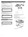
Caution
Use of this manual should be strictly supervised to avoid disclosure of confidential information.
Introduction
Symbols Used
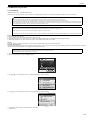
This documentation uses the following symbols to indicate special information:
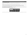
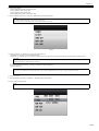
Symbol
Description
Indicates an item of a non-specific nature, possibly classified as Note, Caution, or Warning.
Indicates an item requiring care to avoid electric shocks.
Indicates an item requiring care to avoid combustion (fire).
Indicates an item prohibiting disassembly to avoid electric shocks or problems.
Indicates an item requiring disconnection of the power plug from the electric outlet.
Indicates an item intended to provide notes assisting the understanding of the topic in question.
Memo
Indicates an item of reference assisting the understanding of the topic in question.
REF.
Provides a description of a service mode.
Provides a description of the nature of an error indication.
Introduction
The following rules apply throughout this Service Manual:
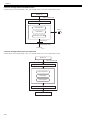
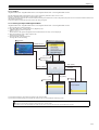
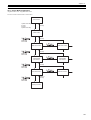
1. Each chapter contains sections explaining the purpose of specific functions and the relationship between electrical and mechanical systems with reference to the timing of operation.
In the diagrams,
represents the path of mechanical drive; where a signal name accompanies the symbol , the arrow
indicates the
direction of the electric signal.
The expression "turn on the power" means flipping on the power switch, closing the front door, and closing the delivery unit door, which results in
supplying the machine with power.
2. In the digital circuits, '1'is used to indicate that the voltage level of a given signal is "High", while '0' is used to indicate "Low".(The voltage value, however, differs from circuit to circuit.) In addition, the asterisk (*) as in "DRMD*" indicates that the DRMD signal goes on when '0'.
In practically all cases, the internal mechanisms of a microprocessor cannot be checked in the field. Therefore, the operations of the microprocessors
used in the machines are not discussed: they are explained in terms of from sensors to the input of the DC controller PCB and from the output of the
DC controller PCB to the loads.
The descriptions in this Service Manual are subject to change without notice for product improvement or other purposes, and major changes will be communicated in the form of Service Information bulletins.
All service persons are expected to have a good understanding of the contents of this Service Manual and all relevant Service Information bulletins and be
able to identify and isolate faults in the machine."
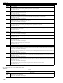
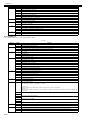
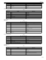
Contents
Contents
Chapter 1 Introduction
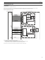
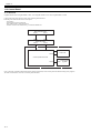
1.1 System Construction ..................................................................................................................................1- 1
1.1.1 System Configuration of Pickup/Delivery Options ................................................................................................... 1- 1
1.1.2 System Configuration of Print/Send Options ........................................................................................................... 1- 2
1.1.3 System Configuration of Print/Send Options ........................................................................................................... 1- 2
1.1.4 Functions of Print/Send Options.............................................................................................................................. 1- 3
1.1.5 Functions of Print/Send Options.............................................................................................................................. 1- 5
1.2 Product Specifications ................................................................................................................................1- 6
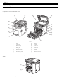
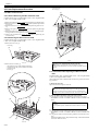
1.2.1 Names of Parts........................................................................................................................................................ 1- 6
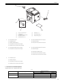
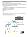
1.2.1.1 External View ........................................................................................................................................................................... 1- 6
1.2.1.2 External View ........................................................................................................................................................................... 1- 7
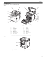
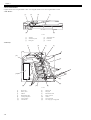
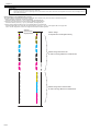
1.2.1.3 Cross Section........................................................................................................................................................................... 1- 8
1.2.2 Using the Machine................................................................................................................................................... 1- 9
1.2.2.1 Turning on the Power Switch ................................................................................................................................................... 1- 9
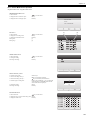
1.2.2.2 Control Panel ......................................................................................................................................................................... 1- 10
1.2.3 User Mode Items ................................................................................................................................................... 1- 11
1.2.3.1 Overview ................................................................................................................................................................................ 1- 11
1.2.3.2 Overview ................................................................................................................................................................................ 1- 11
1.2.3.3 Paper Settings ....................................................................................................................................................................... 1- 11
1.2.3.4 Paper Settings ....................................................................................................................................................................... 1- 11
1.2.3.5 Volume Settings..................................................................................................................................................................... 1- 12
1.2.3.6 Volume Settings..................................................................................................................................................................... 1- 13
1.2.3.7 Common Settings .................................................................................................................................................................. 1- 14
1.2.3.8 Common Settings .................................................................................................................................................................. 1- 15
1.2.3.9 Communications Settings *3.................................................................................................................................................. 1- 16
1.2.3.10 Communications Settings ................................................................................................................................................... 1- 18
1.2.3.11 Address Book Settings......................................................................................................................................................... 1- 20
1.2.3.12 Address Book Settings......................................................................................................................................................... 1- 22
1.2.3.13 Printer Settings..................................................................................................................................................................... 1- 24
1.2.3.14 Printer Settings..................................................................................................................................................................... 1- 26
1.2.3.15 Timer Settings ...................................................................................................................................................................... 1- 30
1.2.3.16 Timer Settings ...................................................................................................................................................................... 1- 31
1.2.3.17 Adjustment/Cleaning ............................................................................................................................................................ 1- 32
1.2.3.18 Adjustment/Cleaning ............................................................................................................................................................ 1- 32
1.2.3.19 Report Settings .................................................................................................................................................................... 1- 32
1.2.3.20 Report Settings .................................................................................................................................................................... 1- 34
1.2.3.21 System Management Set..................................................................................................................................................... 1- 35
1.2.3.22 System Management Settings ............................................................................................................................................. 1- 43
1.2.4 Maintenance by the User....................................................................................................................................... 1- 53
1.2.4.1 Cleaning................................................................................................................................................................................. 1- 53
1.2.4.2 Cleaning................................................................................................................................................................................. 1- 56
1.2.5 Safety .................................................................................................................................................................... 1- 59
1.2.5.1 Points to note at disassembly/assembly ................................................................................................................................ 1- 59
1.2.5.2 CDRH Regulations................................................................................................................................................................. 1- 59
1.2.5.3 Safety of the Laser Light ........................................................................................................................................................ 1- 59
1.2.5.4 Handling the Laser Unit ......................................................................................................................................................... 1- 59
1.2.5.5 Safety of Toner ...................................................................................................................................................................... 1- 60
1.2.5.6 Notes when handling a battery .............................................................................................................................................. 1- 60
1.2.6 Product Specifications ........................................................................................................................................... 1- 61
1.2.6.1 Main Body Specifications....................................................................................................................................................... 1- 61
1.2.6.2 Main Body Specifications....................................................................................................................................................... 1- 62
1.2.6.3 ADF Specifications................................................................................................................................................................. 1- 64
1.2.6.4 ADF Specifications................................................................................................................................................................. 1- 65
1.2.6.5 FAX Specifications................................................................................................................................................................. 1- 66
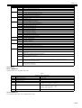
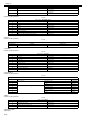
Contents
1.2.6.6 FAX Specifications................................................................................................................................................................. 1- 67
1.2.7 Function List...........................................................................................................................................................1- 68
1.2.7.1 Print Speed ............................................................................................................................................................................ 1- 68
1.2.7.2 Print Speed ............................................................................................................................................................................ 1- 69
1.2.7.3 Paper Type ............................................................................................................................................................................ 1- 70
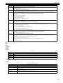
Chapter 2 Installation
2.1 Making Pre-Checks .................................................................................................................................... 2- 1
2.1.1 Checking Installation Environment...........................................................................................................................2- 1
2.1.2 Points to Note Before Installation.............................................................................................................................2- 1
2.1.3 Checking Contents...................................................................................................................................................2- 2
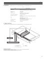
2.2 Unpacking and Installation ......................................................................................................................... 2- 3
2.2.1 Unpacking ................................................................................................................................................................2- 3
2.2.2 Installation................................................................................................................................................................2- 4
2.2.3 Installing Others .......................................................................................................................................................2- 5
2.2.4 Securing Product .....................................................................................................................................................2- 5
2.2.5 Cassette Settings.....................................................................................................................................................2- 6
2.2.6 Points to Note When Turning OFF Host Machine....................................................................................................2- 6
2.2.7 Connecting Cables...................................................................................................................................................2- 6
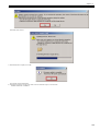
2.2.8 Auto Gradation Adjustment......................................................................................................................................2- 6
2.3 Checking the Connection to the Network ................................................................................................... 2- 7
2.3.1 Setting Up the Network ............................................................................................................................................2- 7
2.3.2 Procedure for Ping Operation ..................................................................................................................................2- 7
2.3.3 Checking with Remote Host Address ......................................................................................................................2- 7
2.3.4 Troubleshooting Network Connection......................................................................................................................2- 7
2.3.5 Checking with Loopback Address............................................................................................................................2- 8
2.3.6 Checking with Local Host Address ..........................................................................................................................2- 8
2.4 Checking the Images/Operations ............................................................................................................... 2- 8
2.4.1 Checking Image Operation ......................................................................................................................................2- 8
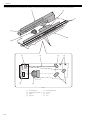
2.5 Installing the Card Reader.......................................................................................................................... 2- 8
2.5.1 Notice At Installation ................................................................................................................................................2- 8
2.5.2 Checking the Contents.............................................................................................................................................2- 8
2.5.3 Turning OFF the Power of the Host Machine ..........................................................................................................2- 9
2.5.4 Installation Procedure ..............................................................................................................................................2- 9
2.5.5 Card ID Registration ..............................................................................................................................................2- 10
2.5.6 Installation Procedure in the imageWARE Accounting Manager (hereinafter referred to iWAM) Environment.....2- 12
2.6 Installing the Hand Set ............................................................................................................................. 2- 12
2.6.1 Points to Note At Installation..................................................................................................................................2- 12
2.6.2 Checking the Contents...........................................................................................................................................2- 12
2.6.3 Turning OFF the Power of the Host Machine ........................................................................................................2- 12
2.6.4 Installation Procedure ............................................................................................................................................2- 12
2.7 Installing the Memory ............................................................................................................................... 2- 13
2.7.1 Checking the Contents...........................................................................................................................................2- 13
2.7.2 Checking Before Memory Expansion.....................................................................................................................2- 14
2.7.3 Turning OFF the Power of the Host Machine ........................................................................................................2- 14
2.7.4 Installation Procedure ............................................................................................................................................2- 14
2.7.5 Checking After Memory Expansion........................................................................................................................2- 14
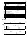
Chapter 3 Basic Operation
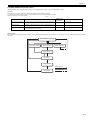
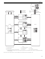
3.1 Construction ............................................................................................................................................... 3- 1
3.1.1 Functional Configuration ..........................................................................................................................................3- 1
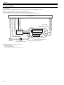
3.1.2 Connecting the Main PCBs......................................................................................................................................3- 2
3.2 Basic Sequence ......................................................................................................................................... 3- 3
3.2.1 Basic Sequence of Operation ..................................................................................................................................3- 3
Contents
3.2.2 Power-On Sequence ............................................................................................................................................... 3- 4
Chapter 4 Main Controller
4.1 Overview/Configuration ..............................................................................................................................4- 1
4.1.1 Overview.................................................................................................................................................................. 4- 1
4.1.2 Configurations/functions .......................................................................................................................................... 4- 2
4.2 Set-Up Sequence .......................................................................................................................................4- 4
4.2.1 Overview.................................................................................................................................................................. 4- 4
4.2.2 Startup Sequence.................................................................................................................................................... 4- 5
4.3 Image Processing .......................................................................................................................................4- 6
4.3.1 Overview of the Image Flow .................................................................................................................................... 4- 6
4.3.2 Construction of the Image Processing Module........................................................................................................ 4- 6
4.3.3 Reader Unit Input Image Processing....................................................................................................................... 4- 7
4.3.4 Compression/ Extesion/ Editing Block..................................................................................................................... 4- 7
4.3.5 Printer unit Output Image Processing...................................................................................................................... 4- 8
4.4 Image Data Flow ........................................................................................................................................4- 9
4.4.1 Flow of Image Data According to Copy Functions .................................................................................................. 4- 9
4.4.2 Flow of Image Data for the SEND Function .......................................................................................................... 4- 10
4.4.3 Flow of Image Data for the Fax Transmission....................................................................................................... 4- 10
4.4.4 Flow of Image Data for the Fax Reception Function ............................................................................................. 4- 11
4.4.5 Flow of Image Data for the PDL Function ............................................................................................................. 4- 11
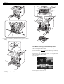
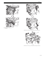
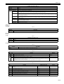
4.5 Parts Replacement Procedure .................................................................................................................4- 12
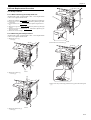
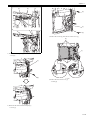
4.5.1 Main Controller PCB.............................................................................................................................................. 4- 12
4.5.1.1 Before Removing the Main Controller PCB ........................................................................................................................... 4- 12
4.5.1.2 Removing the Main Controller PCB ....................................................................................................................................... 4- 12
4.5.1.3 Procedure after Replacing the Main Controller PCB ............................................................................................................. 4- 12
Chapter 5 Original Exposure System
5.1 Basic Construction......................................................................................................................................5- 1
5.1.1 Overview.................................................................................................................................................................. 5- 1
5.1.2 Major Components .................................................................................................................................................. 5- 1
5.2 Basic Sequence..........................................................................................................................................5- 3
5.2.1 Basic Sequence of Operation at Power-on ............................................................................................................. 5- 3
5.2.2 Basic Sequence of Operation in Response to a Press on the Start Key (book)...................................................... 5- 4
5.2.3 Basic Sequence of Operation in Response to a Press on the Start Key (book)...................................................... 5- 5
5.3 Various Control ...........................................................................................................................................5- 6
5.3.1 Lamp Control ........................................................................................................................................................... 5- 6
5.3.1.1 Overview .................................................................................................................................................................................. 5- 6
5.3.2 Enlargement/Reduction ........................................................................................................................................... 5- 7
5.3.2.1 Overview .................................................................................................................................................................................. 5- 7
5.3.3 Detecting the Size of Originals ................................................................................................................................ 5- 7
5.3.3.1 Overview .................................................................................................................................................................................. 5- 7
5.3.4 Dirt Sensor Control .................................................................................................................................................. 5- 8
5.3.4.1 Overview .................................................................................................................................................................................. 5- 8
5.3.4.2 Stream Reading Position Shift ................................................................................................................................................. 5- 8
5.4 Parts Replacement Procedure ...................................................................................................................5- 9
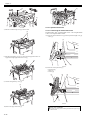
5.4.1 ADF Unit + Reader Unit........................................................................................................................................... 5- 9
5.4.1.1 Before Removing the ADF Unit + Reader Unit ........................................................................................................................ 5- 9
5.4.1.2 Removing the ADF Unit + Reader Unit .................................................................................................................................... 5- 9
5.4.1.3 Procedure after Replacing the ADF Unit................................................................................................................................ 5- 11
5.4.1.4 Procedure after Replacing the Reader Unit ........................................................................................................................... 5- 11
5.4.2 Reader Unit ........................................................................................................................................................... 5- 11
5.4.2.1 Before Removing the Reader Unit ......................................................................................................................................... 5- 11
5.4.2.2 Removing the Reader Unit..................................................................................................................................................... 5- 11
5.4.2.3 Procedure after Replacing the Reader Unit ........................................................................................................................... 5- 12
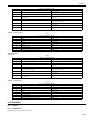
Contents
Chapter 6 Original Feeding System
6.1 Basic Construction ..................................................................................................................................... 6- 1
6.1.1 Overview ..................................................................................................................................................................6- 1
6.2 Basic Operation .......................................................................................................................................... 6- 3
6.2.1 Operation Mode .......................................................................................................................................................6- 3
6.2.2 Document Size Detection ........................................................................................................................................6- 5
6.3 Detection Jams........................................................................................................................................... 6- 6
6.3.1 Overview ..................................................................................................................................................................6- 6
6.4 ADF/DADF ................................................................................................................................................. 6- 7
6.4.1 ADF/DADF ...............................................................................................................................................................6- 7
6.4.1.1 Removing the ADF unit............................................................................................................................................................ 6- 7
6.4.1.2 Procedure after Replacing the ADF Unit.................................................................................................................................. 6- 8
6.4.2 Pickup Feed Unit......................................................................................................................................................6- 8
6.4.2.1 Removing the ADF Pickup Feed Unit ...................................................................................................................................... 6- 8
6.4.3 Pick-up Roller.........................................................................................................................................................6- 10
6.4.3.1 Removing the ADF Pickup Roller .......................................................................................................................................... 6- 10
6.4.4 Separation Roller ...................................................................................................................................................6- 11
6.4.4.1 Removing the ADF Separation Roller.................................................................................................................................... 6- 11
6.4.5 Pick-up Motor.........................................................................................................................................................6- 12
6.4.5.1 Before Removing the ADF Pickup Motor ............................................................................................................................... 6- 12
6.4.5.2 Removing the ADF Pickup Motor........................................................................................................................................... 6- 12
6.4.6 Pick-up Solenoid ....................................................................................................................................................6- 13
6.4.6.1 Before Removing the ADF Pickup Solenoid .......................................................................................................................... 6- 13
6.4.6.2 Removing the ADF Pickup Solenoid...................................................................................................................................... 6- 13
6.4.7 Separation Pad ......................................................................................................................................................6- 14
6.4.7.1 Removing the ADF Separation Pad....................................................................................................................................... 6- 14
Chapter 7 Laser Exposure
7.1 Overview/Configuration .............................................................................................................................. 7- 1
7.1.1 Overview ..................................................................................................................................................................7- 1
7.1.2 Overview ..................................................................................................................................................................7- 3
7.2 Controlling the Laser .................................................................................................................................. 7- 5
7.2.1 Overview ..................................................................................................................................................................7- 5
7.2.2 Overview ..................................................................................................................................................................7- 6
7.2.3 Laser Light Emission Control ...................................................................................................................................7- 7
7.2.4 Laser Light Intensity Control ....................................................................................................................................7- 7
7.2.5 Laser Light Intensity Control ....................................................................................................................................7- 7
7.2.6 Image Masking Control ............................................................................................................................................7- 7
7.2.7 Failure Detection......................................................................................................................................................7- 7
7.3 Controlling the Laser Scanner Motor.......................................................................................................... 7- 8
7.3.1 Overview ..................................................................................................................................................................7- 8
7.3.2 Failure Detection......................................................................................................................................................7- 8
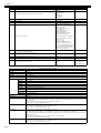
7.4 Parts Replacement Procedure ................................................................................................................... 7- 9
7.4.1 Laser/Scanner Unit ..................................................................................................................................................7- 9
7.4.1.1 Before Removing the Laser Scanner Unit ............................................................................................................................... 7- 9
7.4.1.2 Removing the Laser Scanner Unit ........................................................................................................................................... 7- 9
Chapter 8 Image Formation
8.1 Overview/Configuration .............................................................................................................................. 8- 1
8.1.1 Overview ..................................................................................................................................................................8- 1
8.1.2 Print Process............................................................................................................................................................8- 2
8.1.3 Electrostatic Latent Image Formation Block ............................................................................................................8- 3
8.1.4 Development Block ..................................................................................................................................................8- 4
8.1.5 Transfer Block..........................................................................................................................................................8- 4
Contents
8.1.6 Fixing Block ............................................................................................................................................................. 8- 6
8.1.7 Cleaning Block......................................................................................................................................................... 8- 6
8.2 Image Stabilization Control.........................................................................................................................8- 7
8.2.1 Overview.................................................................................................................................................................. 8- 7
8.2.2 Environmental Change Corrective Control .............................................................................................................. 8- 8
8.2.3 D-half Control .......................................................................................................................................................... 8- 9
8.2.4 Color Displacement Corrective Control ................................................................................................................. 8- 11
8.2.5 Auto Gradation Correction Control ........................................................................................................................ 8- 13
8.3 Toner Cartridge ........................................................................................................................................8- 14
8.3.1 Overview................................................................................................................................................................ 8- 14
8.3.2 Toner Level Detection ........................................................................................................................................... 8- 15
8.3.3 Memory Tag Control.............................................................................................................................................. 8- 15
8.3.4 Toner Cartridge Detection ..................................................................................................................................... 8- 15
8.3.5 New Toner Cartridge Detection ............................................................................................................................. 8- 16
8.3.6 Developing Cylinder Engagement/disengagement Control................................................................................... 8- 17
8.4 Transfer Unit .............................................................................................................................................8- 18
8.4.1 ETB Unit ................................................................................................................................................................ 8- 18
8.4.2 Automatic Bias Control .......................................................................................................................................... 8- 19
8.4.3 ETB Cleaning ........................................................................................................................................................ 8- 20
8.4.4 Transfer Roller Engagement/disengagement Control ........................................................................................... 8- 21
8.5 Parts Replacement Procedure .................................................................................................................8- 25
8.5.1 Drum Motor............................................................................................................................................................ 8- 25
8.5.1.1 Before Removing the Drum Motor ......................................................................................................................................... 8- 25
8.5.1.2 Removing the Drum Motor..................................................................................................................................................... 8- 25
8.5.2 Main Drive Unit ...................................................................................................................................................... 8- 25
8.5.2.1 Before Removing the Main Drive Unit.................................................................................................................................... 8- 25
8.5.2.2 Removing the Main Drive Unit ............................................................................................................................................... 8- 25
8.5.2.3 Point to Note When Installing the Main Drive Unit ................................................................................................................. 8- 27
8.5.3 Developing Estrangement Solenoid ...................................................................................................................... 8- 29
8.5.3.1 Before Removing the Developing Disengage Solenoid ......................................................................................................... 8- 29
8.5.3.2 Removing the Developing Disengage Solenoid..................................................................................................................... 8- 29
8.5.3.3 Points to Note When Installing the Developing Disengage Solenoid..................................................................................... 8- 30
8.5.4 ETB Unit ................................................................................................................................................................ 8- 30
8.5.4.1 Removing the ETB Unit ......................................................................................................................................................... 8- 30
8.5.5 ETB Motor ............................................................................................................................................................. 8- 31
8.5.5.1 Before Removing the ETB Motor ........................................................................................................................................... 8- 31
8.5.5.2 Removing the ETB Motor....................................................................................................................................................... 8- 31
8.5.6 ETB Estrangement Solenoid ................................................................................................................................. 8- 32
8.5.6.1 Before Removing the ETB Disengage Solenoid .................................................................................................................... 8- 32
8.5.6.2 Removing the ETB Disengage Solenoid................................................................................................................................ 8- 32
8.5.7 Color Displacement/Image Density Sensor ........................................................................................................... 8- 33
8.5.7.1 Before Removing the Color Displacement/Density Sensor ................................................................................................... 8- 33
8.5.7.2 Removing the Color Displacement/Density Sensor ............................................................................................................... 8- 33
Chapter 9 Pickup and Feed System
9.1 Overview/Configuration ..............................................................................................................................9- 1
9.1.1 Overview.................................................................................................................................................................. 9- 1
9.1.2 Interval Speed Increase Control .............................................................................................................................. 9- 3
9.1.3 Interval Speed Increase Control .............................................................................................................................. 9- 4
9.2 Other Control ..............................................................................................................................................9- 5
9.2.1 Cassette Pickup Mechanism ................................................................................................................................... 9- 5
9.2.2 Manual Feed Pickup Mechanism ............................................................................................................................ 9- 6
9.2.3 Skew Correction ...................................................................................................................................................... 9- 7
9.2.4 Throughput-down Control........................................................................................................................................ 9- 8
9.2.5 Throughput-down Control........................................................................................................................................ 9- 9
9.2.6 Feeding Speed Control.......................................................................................................................................... 9- 10
Contents
9.2.7 Feeding Speed Control ..........................................................................................................................................9- 10
9.2.8 Warp Control..........................................................................................................................................................9- 10
9.2.9 Delivery ..................................................................................................................................................................9- 12
9.3 Detection Jams......................................................................................................................................... 9- 14
9.3.1 Jam Detection Outline............................................................................................................................................9- 14
9.3.1.1 Overview ................................................................................................................................................................................ 9- 14
9.3.2 Delay Jams ............................................................................................................................................................9- 14
9.3.2.1 Pickup Delay JAM.................................................................................................................................................................. 9- 14
9.3.2.2 Delivery Delay JAM................................................................................................................................................................ 9- 14
9.3.2.3 Duplexing Pickup Delay JAM................................................................................................................................................. 9- 14
9.3.2.4 Duplexing Reverse Unit Delay JAM....................................................................................................................................... 9- 14
9.3.3 Stationary Jams .....................................................................................................................................................9- 15
9.3.3.1 Pickup Stationary JAM........................................................................................................................................................... 9- 15
9.3.3.2 Delivery Stationary JAM......................................................................................................................................................... 9- 15
9.3.4 Other Jams ............................................................................................................................................................9- 15
9.3.4.1 Wrapping JAM ....................................................................................................................................................................... 9- 15
9.3.4.2 Residual JAM......................................................................................................................................................................... 9- 15
9.3.4.3 Door Open JAM ..................................................................................................................................................................... 9- 15
9.3.4.4 Automatic Delivery Function .................................................................................................................................................. 9- 15
9.4 Duplex Feeding ........................................................................................................................................ 9- 16
9.4.1 Overview ................................................................................................................................................................9- 16
9.4.2 Duplexing Feed Control .........................................................................................................................................9- 17
9.4.3 Duplexing Pickup Operation ..................................................................................................................................9- 20
9.5 Parts Replacement Procedure ................................................................................................................. 9- 21
9.5.1 Pickup Feed Unit....................................................................................................................................................9- 21
9.5.1.1 Before Removing the Pickup Feed Unit................................................................................................................................. 9- 21
9.5.1.2 Removing the Pickup Feed Unit ............................................................................................................................................ 9- 21
9.5.2 Cassette Pickup Roller...........................................................................................................................................9- 22
9.5.2.1 Before Removing the Cassette Pickup Roller........................................................................................................................ 9- 22
9.5.2.2 Removing the Cassette Pickup Roller ................................................................................................................................... 9- 22
9.5.3 Pickup Motor ..........................................................................................................................................................9- 23
9.5.3.1 Before Removing the Pickup Motor ....................................................................................................................................... 9- 23
9.5.3.2 Removing the Pickup Motor................................................................................................................................................... 9- 23
9.5.4 Cassette Pickup Solenoid ......................................................................................................................................9- 24
9.5.4.1 Before Removing the Cassette Pickup Solenoid ................................................................................................................... 9- 24
9.5.4.2 Removing the Cassette Pickup Solenoid............................................................................................................................... 9- 24
9.5.5 Cassette Separation Pad .......................................................................................................................................9- 26
9.5.5.1 Removing the Cassette Separation Pad................................................................................................................................ 9- 26
9.5.6 Manual Pickup Roller .............................................................................................................................................9- 26
9.5.6.1 Before Removing the Manual Feed Pickup Roller ................................................................................................................. 9- 26
9.5.6.2 Removing the Manual Feed Pickup Roller............................................................................................................................. 9- 26
9.5.7 Manual Pickup Solenoid ........................................................................................................................................9- 26
9.5.7.1 Before Removing the Manual Feed Pickup Solenoid ............................................................................................................ 9- 26
9.5.7.2 Removing the Manual Feed Pickup Solenoid ........................................................................................................................ 9- 26
9.5.8 Manual Separation Roller ......................................................................................................................................9- 28
9.5.8.1 Before Removing the Manual Feed Separation Pad ............................................................................................................. 9- 28
9.5.8.2 Removing the Manual Feed Separation Pad ......................................................................................................................... 9- 28
9.5.9 Duplexing Feed Motor............................................................................................................................................9- 29
9.5.9.1 Before Removing the Duplex Feed Motor.............................................................................................................................. 9- 29
9.5.9.2 Removing the Duplex Feed Motor ......................................................................................................................................... 9- 29
9.5.10 Reverse Unit ........................................................................................................................................................9- 29
9.5.10.1 Before Removing the Reversal Unit..................................................................................................................................... 9- 29
9.5.10.2 Removing the Reversal Unit ................................................................................................................................................ 9- 29
9.5.11 Reverse Motor......................................................................................................................................................9- 31
9.5.11.1 Before Removing the Reversal Motor .................................................................................................................................. 9- 31
9.5.11.2 Removing the Reversal Motor.............................................................................................................................................. 9- 31
9.5.12 Reverse Solenoid.................................................................................................................................................9- 31
9.5.12.1 Before Removing the Reversal Solenoid ............................................................................................................................. 9- 31
9.5.12.2 Removing the Reversal Solenoid......................................................................................................................................... 9- 31
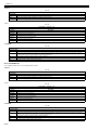
Contents
Chapter 10 Fixing System
10.1 Overview/Configuration ..........................................................................................................................10- 1
10.1.1 Overview.............................................................................................................................................................. 10- 1
10.2 Various Control Mechanisms ..................................................................................................................10- 2
10.2.1 Controlling the Temperature of the Fixing Unit .................................................................................................... 10- 2
10.2.1.1 Fixing Temperature Control ................................................................................................................................................. 10- 2
10.2.1.2 Throughput Down Control .................................................................................................................................................... 10- 3
10.2.2 Fixing Pressurizing/Release Control.................................................................................................................... 10- 4
10.2.2.1 Fixing Sleeve Pressuring/releasing Control ......................................................................................................................... 10- 4
10.2.2.2 Fixing Sleeve Pressuring/releasing Control ......................................................................................................................... 10- 5
10.3 Protection Function .................................................................................................................................10- 7
10.3.1 Overview.............................................................................................................................................................. 10- 7
10.3.2 Failure Detection.................................................................................................................................................. 10- 7
10.4 Parts Replacement Procedure................................................................................................................10- 8
10.4.1 Fixing Unit............................................................................................................................................................ 10- 8
10.4.1.1 Removing the Fixing Assembly............................................................................................................................................ 10- 8
10.4.2 Fixing Sleeve Unit................................................................................................................................................ 10- 8
10.4.2.1 Before Removing the Fixing Sleeve Unit ............................................................................................................................. 10- 8
10.4.2.2 Removing the Fixing Sleeve Unit ......................................................................................................................................... 10- 8
10.4.3 Fixing Drive Unit ................................................................................................................................................ 10- 12
10.4.3.1 Before Removing the Fixing Drive Unit .............................................................................................................................. 10- 12
10.4.3.2 Removing the Fixing Drive Unit.......................................................................................................................................... 10- 12
10.4.4 Fixing Motor ....................................................................................................................................................... 10- 14
10.4.4.1 Before Removing the Fixing Motor..................................................................................................................................... 10- 14
10.4.4.2 Removing the Fixing Motor ................................................................................................................................................ 10- 15
Chapter 11 External and Controls
11.1 DC Controller ..........................................................................................................................................11- 1
11.1.1 Overview.............................................................................................................................................................. 11- 1
11.1.2 Operation of Each Block ...................................................................................................................................... 11- 2
11.1.3 Fan/Motor Control................................................................................................................................................ 11- 2
11.1.4 Drum motor failure detection ............................................................................................................................... 11- 3
11.1.5 ETB motor failure detection ................................................................................................................................. 11- 3
11.1.6 Fixing motor failure detection............................................................................................................................... 11- 3
11.1.7 Main Unit Fan Failure Detection .......................................................................................................................... 11- 3
11.1.8 Duplex Fan Failure Detection .............................................................................................................................. 11- 3
11.2 Control Panel ..........................................................................................................................................11- 4
11.2.1 Overview.............................................................................................................................................................. 11- 4
11.3 Counter ...................................................................................................................................................11- 5
11.3.1 Overview.............................................................................................................................................................. 11- 5
11.3.2 Overview.............................................................................................................................................................. 11- 6
11.3.3 Timing of Increasing the Count............................................................................................................................ 11- 6
11.4 Power Supply..........................................................................................................................................11- 7
11.4.1 Power Supply....................................................................................................................................................... 11- 7
11.4.1.1 Low-voltage Power Unit ....................................................................................................................................................... 11- 7
11.4.2 Protection Function.............................................................................................................................................. 11- 8
11.4.2.1 Protective Function .............................................................................................................................................................. 11- 8
11.4.2.2 Safety ................................................................................................................................................................................... 11- 8
11.4.3 Energy-Saving Function ...................................................................................................................................... 11- 8
11.4.3.1 Overview .............................................................................................................................................................................. 11- 8
11.5 Parts Replacement Procedure..............................................................................................................11- 10
11.5.1 Front Cover........................................................................................................................................................ 11- 10
11.5.1.1 Before Removing the Front Cover Unit .............................................................................................................................. 11- 10
11.5.1.2 Removing the Front Cover Unit.......................................................................................................................................... 11- 10
11.5.2 Front Upper Cover 1 .......................................................................................................................................... 11- 11
11.5.2.1 Before Removing Front upper Cover 1 .............................................................................................................................. 11- 11
Contents
11.5.2.2 Removing Front Upper Cover 1 ......................................................................................................................................... 11- 11
11.5.3 Rear Cover.........................................................................................................................................................11- 12
11.5.3.1 Removing the Rear Cover Unit .......................................................................................................................................... 11- 12
11.5.4 Right Cover ........................................................................................................................................................11- 12
11.5.4.1 Before Removing the Right Cover ..................................................................................................................................... 11- 12
11.5.4.2 Removing the Right Cover ................................................................................................................................................. 11- 12
11.5.5 Left Cover...........................................................................................................................................................11- 14
11.5.5.1 Before Removing the Left Cover........................................................................................................................................ 11- 14
11.5.5.2 Removing the Left Cover ................................................................................................................................................... 11- 14
11.5.6 Delivery Tray Cover ...........................................................................................................................................11- 15
11.5.6.1 Before Removing the Delivery Tray Cover......................................................................................................................... 11- 15
11.5.6.2 Removing the Delivery Tray Cover .................................................................................................................................... 11- 15
11.5.7 Power Station Cover ..........................................................................................................................................11- 16
11.5.7.1 Before Removing the Electrical Components Cover.......................................................................................................... 11- 16
11.5.7.2 Removing the Electrical Components Cover ..................................................................................................................... 11- 16
11.5.8 Controller Box ....................................................................................................................................................11- 16
11.5.8.1 Before Removing the Controller Box.................................................................................................................................. 11- 16
11.5.8.2 Removing the Controller Box ............................................................................................................................................. 11- 16
11.5.9 Laser Scanner Cover .........................................................................................................................................11- 17
11.5.9.1 Before Removing the Laser Scanner Cover ...................................................................................................................... 11- 17
11.5.9.2 Removing the Laser Scanner Cover .................................................................................................................................. 11- 17
11.5.10 Upper Frame Unit.............................................................................................................................................11- 20
11.5.10.1 Before Removing the Upper Frame Unit .......................................................................................................................... 11- 20
11.5.10.2 Removing the Upper Frame Unit...................................................................................................................................... 11- 20
11.5.11 Operation Panel Unit ........................................................................................................................................11- 22
11.5.11.1 Removing the Control Panel Unit ..................................................................................................................................... 11- 22
11.5.11.2 Procedure after Replacing the Control Panel................................................................................................................... 11- 23
11.5.12 NCU Board .......................................................................................................................................................11- 23
11.5.12.1 Before Removing the NCU PCB ...................................................................................................................................... 11- 23
11.5.12.2 Removing the NCU PCB .................................................................................................................................................. 11- 23
11.5.13 DC Controller PCB ...........................................................................................................................................11- 24
11.5.13.1 Before Removing the DC Controller PCB ........................................................................................................................ 11- 24
11.5.13.2 Removing the DC Controller PCB .................................................................................................................................... 11- 24
11.5.13.3 Procedure after Replacing the DC controller PCB ........................................................................................................... 11- 24
11.5.14 Memory Controller PCB ...................................................................................................................................11- 24
11.5.14.1 Before Removing the Memory Controller PCB................................................................................................................. 11- 24
11.5.14.2 Removing the Memory Controller PCB ............................................................................................................................ 11- 24
11.5.15 Duplexing Driver PCB ......................................................................................................................................11- 25
11.5.15.1 Before Removing the Duplex Driver PCB ........................................................................................................................ 11- 25
11.5.15.2 Removing the Duplex Driver PCB .................................................................................................................................... 11- 25
11.5.16 Low-voltage Power Supply PCB ......................................................................................................................11- 25
11.5.16.1 Before Removing the Low-Voltage Power Supply PCB ................................................................................................... 11- 25
11.5.16.2 Removing the Low Voltage Power Supply PCB............................................................................................................... 11- 25
11.5.17 High-voltage Power Supply PCB......................................................................................................................11- 26
11.5.17.1 Before Removing the High Voltage Power Supply PCB .................................................................................................. 11- 26
11.5.17.2 Removing the High Voltage Power Supply PCB .............................................................................................................. 11- 27
11.5.18 Off Hook PCB...................................................................................................................................................11- 27
11.5.18.1 Before Removing the Off Hook PCB ................................................................................................................................ 11- 27
11.5.18.2 Removing the Off Hook PCB............................................................................................................................................ 11- 27
11.5.19 Cooling Fan ......................................................................................................................................................11- 27
11.5.19.1 Before Removing the Cooling Fan ................................................................................................................................... 11- 27
11.5.19.2 Removing the Cooling Fan............................................................................................................................................... 11- 27
11.5.20 Duplex Fan .......................................................................................................................................................11- 28
11.5.20.1 Before Removing the Duplex Fan .................................................................................................................................... 11- 28
11.5.20.2 Removing the Duplex Fan................................................................................................................................................ 11- 28
Chapter 12 e-Maintenance/imageWARE Remote
12.1 e-Maintenance/imageWARE Remote..................................................................................................... 12- 1
12.1.1 Overview ..............................................................................................................................................................12- 1
Contents
12.1.2 Setting Procedure ................................................................................................................................................ 12- 1
12.1.3 Troubleshooting guide ....................................................................................................................................... 12- 10
12.1.4 Service cautions ................................................................................................................................................ 12- 12
12.1.5 Overview............................................................................................................................................................ 12- 13
12.1.6 Service cautions ................................................................................................................................................ 12- 14
12.1.7 Setting Procedure .............................................................................................................................................. 12- 15
12.1.8 FAQ ................................................................................................................................................................... 12- 28
12.1.9 Troubleshooting ................................................................................................................................................. 12- 29
12.1.10 Error code and strings...................................................................................................................................... 12- 32
Chapter 13 Maintenance and Inspection
13.1 Periodically Replaced Parts ....................................................................................................................13- 1
13.1.1 Periodically Replaced Parts................................................................................................................................. 13- 1
13.2 Consumables ..........................................................................................................................................13- 1
13.2.1 Expected Service Life of Consumable Parts ....................................................................................................... 13- 1
13.3 Periodical Service ...................................................................................................................................13- 1
13.3.1 Periodic Service................................................................................................................................................... 13- 1
Chapter 14 Measurement and Adjustments
14.1 Scanning System ....................................................................................................................................14- 1
14.1.1 Procedure after Replacing the Copyboard Glass ................................................................................................ 14- 1
14.1.2 Procedure after Replacing the Reader Unit......................................................................................................... 14- 1
14.2 Fixing System .........................................................................................................................................14- 1
14.2.1 Checking the Nip Width (fixing pressure roller) ................................................................................................... 14- 1
14.3 Electrical Components ............................................................................................................................14- 1
14.3.1 Procedure after Replacing the DC controller PCB............................................................................................... 14- 1
14.3.2 Procedure after Replacing the Main Controller PCB ........................................................................................... 14- 1
14.3.3 Procedure after Clearing RAM Data .................................................................................................................... 14- 1
14.3.4 Procedure after Replacing the Control Panel ...................................................................................................... 14- 2
14.4 ADF.........................................................................................................................................................14- 2
14.4.1 Outline ................................................................................................................................................................. 14- 2
14.4.1.1 Procedure after Replacing the ADF Unit.............................................................................................................................. 14- 2
Chapter 15 Correcting Faulty Images
15.1 Initial Checkup ........................................................................................................................................15- 1
15.1.1 Initial Check ......................................................................................................................................................... 15- 1
15.2 Test Printing............................................................................................................................................15- 2
15.2.1 Test Printing......................................................................................................................................................... 15- 2
15.3 Outline of Electrical Components............................................................................................................15- 6
15.3.1 Clutch/Solenoid.................................................................................................................................................... 15- 6
15.3.1.1 Solenoids ............................................................................................................................................................................. 15- 6
15.3.2 Motor/Fan ............................................................................................................................................................ 15- 7
15.3.2.1 Motors .................................................................................................................................................................................. 15- 7
15.3.2.2 Fans ..................................................................................................................................................................................... 15- 8
15.3.3 Sensor ................................................................................................................................................................. 15- 9
15.3.3.1 Sensors ................................................................................................................................................................................ 15- 9
15.3.4 Switch ................................................................................................................................................................ 15- 11
15.3.4.1 Switches, Speaker, and Thermistors ................................................................................................................................. 15- 11
15.3.5 PCBs.................................................................................................................................................................. 15- 13
15.3.5.1 PCBs .................................................................................................................................................................................. 15- 13
15.3.6 Location of Convectors ...................................................................................................................................... 15- 15
15.3.6.1 Location of Connectors ...................................................................................................................................................... 15- 15
Contents
Chapter 16 Error Code
16.1 Error Code Table .................................................................................................................................... 16- 1
16.1.1 Error Code Table..................................................................................................................................................16- 1
16.2 Error Code Details .................................................................................................................................. 16- 2
16.2.1 Error Code Details................................................................................................................................................16- 2
16.3 Jam Code ............................................................................................................................................... 16- 8
16.3.1 Jam Code (main body).........................................................................................................................................16- 8
16.3.2 Jam Code (ADF) ..................................................................................................................................................16- 8
16.4 Alarm Code............................................................................................................................................. 16- 9
16.4.1 Alarm Code (ADF)................................................................................................................................................16- 9
16.5 Fax Error Codes ..................................................................................................................................... 16- 9
16.5.1 Outline..................................................................................................................................................................16- 9
16.5.1.1 Error Code Outline ............................................................................................................................................................... 16- 9
16.5.2 User Error Code ...................................................................................................................................................16- 9
16.5.2.1 User Error Code ................................................................................................................................................................... 16- 9
16.5.3 Service Error Code...............................................................................................................................................16- 9
16.5.3.1 Service Error Code............................................................................................................................................................... 16- 9
Chapter 17 Special Management Mode
17.1 Overview................................................................................................................................................. 17- 1
17.1.1 Preface.................................................................................................................................................................17- 1
17.1.2 Entering the Special Management Mode .............................................................................................................17- 1
17.1.3 Menu List..............................................................................................................................................................17- 2
17.2 Troubleshooting ...................................................................................................................................... 17- 3
17.2.1 Pre-Check ............................................................................................................................................................17- 3
17.2.2 User Request .......................................................................................................................................................17- 3
17.2.3 Paper Error...........................................................................................................................................................17- 3
17.2.4 Image error...........................................................................................................................................................17- 3
Chapter 18 Service Mode
18.1 Outline .................................................................................................................................................... 18- 1
18.1.1 Service Mode Configuration.................................................................................................................................18- 1
18.1.2 Service Mode Configuration.................................................................................................................................18- 3
18.1.3 Exiting Service Mode ...........................................................................................................................................18- 5
18.1.4 Exiting Service Mode ...........................................................................................................................................18- 5
18.1.5 Service Mode Backup ..........................................................................................................................................18- 5
18.1.6 Service Mode Backup ..........................................................................................................................................18- 6
18.1.7 Service Mode Screen Operation ..........................................................................................................................18- 7
18.1.8 Service Mode Screen Operation ..........................................................................................................................18- 9
18.2 COPIER ................................................................................................................................................ 18- 11
18.2.1 DISPLAY ............................................................................................................................................................18- 11
18.2.1.1 DISPLAY List ..................................................................................................................................................................... 18- 11
18.2.1.2 DISPLAY List ..................................................................................................................................................................... 18- 11
18.2.2 I/O ......................................................................................................................................................................18- 12
18.2.2.1 R-CON ............................................................................................................................................................................... 18- 12
18.2.2.2 R-CON ............................................................................................................................................................................... 18- 12
18.2.3 ADJUST .............................................................................................................................................................18- 12
18.2.3.1 ADJUST List....................................................................................................................................................................... 18- 12
18.2.3.2 ADJUST List....................................................................................................................................................................... 18- 17
18.2.4 FUNCTION.........................................................................................................................................................18- 21
18.2.4.1 FUNCTION List .................................................................................................................................................................. 18- 21
18.2.4.2 FUNCTION List .................................................................................................................................................................. 18- 26
18.2.4.3 Adjustment of the ACS identification level ......................................................................................................................... 18- 32
18.2.4.4 Adjustment of the ACS identification level ......................................................................................................................... 18- 33
Contents
18.2.5 OPTION ............................................................................................................................................................. 18- 33
18.2.5.1 OPTION List....................................................................................................................................................................... 18- 33
18.2.5.2 OPTION List....................................................................................................................................................................... 18- 43
18.2.6 COUNTER ......................................................................................................................................................... 18- 53
18.2.6.1 COUNTER List................................................................................................................................................................... 18- 53
18.2.6.2 COUNTER List................................................................................................................................................................... 18- 54
18.3 FEEDER ...............................................................................................................................................18- 56
18.3.1 ADJUST............................................................................................................................................................. 18- 56
18.3.1.1 ADJUST List....................................................................................................................................................................... 18- 56
18.3.1.2 ADJUST List....................................................................................................................................................................... 18- 56
18.3.2 FUNCTION ........................................................................................................................................................ 18- 56
18.3.2.1 FUNCTION List .................................................................................................................................................................. 18- 56
18.3.2.2 FUNCTION List .................................................................................................................................................................. 18- 56
18.4 FAX .......................................................................................................................................................18- 57
18.4.1 SSSW ................................................................................................................................................................ 18- 57
18.4.1.1 SSSW List .......................................................................................................................................................................... 18- 57
18.4.1.2 SSSW List .......................................................................................................................................................................... 18- 58
18.4.2 MENU ................................................................................................................................................................ 18- 59
18.4.2.1 MENU List .......................................................................................................................................................................... 18- 59
18.4.2.2 MENU List .......................................................................................................................................................................... 18- 59
18.4.3 NUM................................................................................................................................................................... 18- 60
18.4.3.1 NUM List ............................................................................................................................................................................ 18- 60
18.4.3.2 NUM List ............................................................................................................................................................................ 18- 60
18.4.4 NCU ................................................................................................................................................................... 18- 61
18.4.4.1 NCU List............................................................................................................................................................................. 18- 61
18.5 TESTMODE ..........................................................................................................................................18- 65
18.5.1 SYSTEM ............................................................................................................................................................ 18- 65
18.5.1.1 SYSTEM List...................................................................................................................................................................... 18- 65
18.5.1.2 SYSTEM List...................................................................................................................................................................... 18- 66
18.5.2 SCAN................................................................................................................................................................. 18- 67
18.5.2.1 SCAN List........................................................................................................................................................................... 18- 67
18.5.2.2 SCAN List........................................................................................................................................................................... 18- 67
18.5.3 PRINT ................................................................................................................................................................ 18- 68
18.5.3.1 PRINT List.......................................................................................................................................................................... 18- 68
18.5.3.2 PRINT List.......................................................................................................................................................................... 18- 69
18.5.4 FAX.................................................................................................................................................................... 18- 69
18.5.4.1 FAX List.............................................................................................................................................................................. 18- 69
18.5.4.2 FAX List.............................................................................................................................................................................. 18- 70
18.5.5 PANEL ............................................................................................................................................................... 18- 71
18.5.5.1 PANEL List......................................................................................................................................................................... 18- 71
18.5.5.2 PANEL List......................................................................................................................................................................... 18- 73
Chapter 19 Upgrading
19.1 Outline ....................................................................................................................................................19- 1
19.1.1 Overview of Upgrade ........................................................................................................................................... 19- 1
19.2 Making Preparations ...............................................................................................................................19- 2
19.2.1 Required System Environment ............................................................................................................................ 19- 2
19.2.2 Before Upgrade ................................................................................................................................................... 19- 2
19.3 Downloading System Software ...............................................................................................................19- 3
19.3.1 Downloading the System Software...................................................................................................................... 19- 3
19.3.1.1 Downloading Procedure....................................................................................................................................................... 19- 3
19.3.1.2 Downloading Procedure....................................................................................................................................................... 19- 7
Chapter 20 Service Tools
20.1 Service Tools ..........................................................................................................................................20- 1
20.1.1 Special Tools ....................................................................................................................................................... 20- 1
Contents
20.1.2 Standard Tools.....................................................................................................................................................20- 1
20.1.3 Special Tools........................................................................................................................................................20- 2
20.1.4 Standard Tools.....................................................................................................................................................20- 2
20.1.5 Solvent/Oil List .....................................................................................................................................................20- 3
20.1.6 Solvent/Oil List .....................................................................................................................................................20- 3
Chapter 1 Introduction
Contents
Contents
1.1 System Construction ......................................................................................................................................................1-1
1.1.1 System Configuration of Pickup/Delivery Options ..................................................................................................................... 1-1
1.1.2 System Configuration of Print/Send Options .............................................................................................................................. 1-2
1.1.3 System Configuration of Print/Send Options .............................................................................................................................. 1-2
1.1.4 Functions of Print/Send Options .................................................................................................................................................. 1-3
1.1.5 Functions of Print/Send Options .................................................................................................................................................. 1-5
1.2 Product Specifications....................................................................................................................................................1-6
1.2.1 Names of Parts ............................................................................................................................................................................. 1-6
1.2.1.1 External View..................................................................................................................................................................................................1-6
1.2.1.2 External View..................................................................................................................................................................................................1-7
1.2.1.3 Cross Section...................................................................................................................................................................................................1-8
1.2.2 Using the Machine ....................................................................................................................................................................... 1-9
1.2.2.1 Turning on the Power Switch..........................................................................................................................................................................1-9
1.2.2.2 Control Panel.................................................................................................................................................................................................1-10
1.2.3 User Mode Items........................................................................................................................................................................ 1-11
1.2.3.1 Overview .......................................................................................................................................................................................................1-11
1.2.3.2 Overview .......................................................................................................................................................................................................1-11
1.2.3.3 Paper Settings................................................................................................................................................................................................1-11
1.2.3.4 Paper Settings................................................................................................................................................................................................1-11
1.2.3.5 Volume Settings ............................................................................................................................................................................................1-12
1.2.3.6 Volume Settings ............................................................................................................................................................................................1-13
1.2.3.7 Common Settings ..........................................................................................................................................................................................1-14
1.2.3.8 Common Settings ..........................................................................................................................................................................................1-15
1.2.3.9 Communications Settings *3.........................................................................................................................................................................1-16
1.2.3.10 Communications Settings ...........................................................................................................................................................................1-18
1.2.3.11 Address Book Settings ................................................................................................................................................................................1-20
1.2.3.12 Address Book Settings ................................................................................................................................................................................1-22
1.2.3.13 Printer Settings ............................................................................................................................................................................................1-24
1.2.3.14 Printer Settings ............................................................................................................................................................................................1-26
1.2.3.15 Timer Settings .............................................................................................................................................................................................1-30
1.2.3.16 Timer Settings .............................................................................................................................................................................................1-31
1.2.3.17 Adjustment/Cleaning...................................................................................................................................................................................1-32
1.2.3.18 Adjustment/Cleaning...................................................................................................................................................................................1-32
1.2.3.19 Report Settings ............................................................................................................................................................................................1-32
1.2.3.20 Report Settings ............................................................................................................................................................................................1-34
1.2.3.21 System Management Set. ............................................................................................................................................................................1-35
1.2.3.22 System Management Settings .....................................................................................................................................................................1-43
1.2.4 Maintenance by the User ........................................................................................................................................................... 1-53
1.2.4.1 Cleaning ........................................................................................................................................................................................................1-53
1.2.4.2 Cleaning ........................................................................................................................................................................................................1-56
1.2.5 Safety ......................................................................................................................................................................................... 1-59
1.2.5.1 Points to note at disassembly/assembly ........................................................................................................................................................1-59
1.2.5.2 CDRH Regulations........................................................................................................................................................................................1-59
1.2.5.3 Safety of the Laser Light...............................................................................................................................................................................1-59
1.2.5.4 Handling the Laser Unit ................................................................................................................................................................................1-59
1.2.5.5 Safety of Toner..............................................................................................................................................................................................1-60
1.2.5.6 Notes when handling a battery ......................................................................................................................................................................1-60
1.2.6 Product Specifications ............................................................................................................................................................... 1-61
1.2.6.1 Main Body Specifications .............................................................................................................................................................................1-61
1.2.6.2 Main Body Specifications .............................................................................................................................................................................1-62
1.2.6.3 ADF Specifications .......................................................................................................................................................................................1-64
1.2.6.4 ADF Specifications .......................................................................................................................................................................................1-65
1.2.6.5 FAX Specifications .......................................................................................................................................................................................1-66
1.2.6.6 FAX Specifications .......................................................................................................................................................................................1-67
Contents
1.2.7 Function List .............................................................................................................................................................................. 1-68
1.2.7.1 Print Speed .................................................................................................................................................................................................... 1-68
1.2.7.2 Print Speed .................................................................................................................................................................................................... 1-69
1.2.7.3 Paper Type .................................................................................................................................................................................................... 1-70
Chapter 1
1.1 System Construction
1.1.1 System Configuration of Pickup/Delivery Options
0019-4882
imageRUNNER C1022 / imageRUNNER C1022i / Color imageRUNNER C1030 / Color imageRUNNER C1030iF
[1]
F-1-1
[1]
Cassette Feeding Unit-AB1
1-1
Chapter 1
1.1.2 System Configuration of Print/Send Options
0019-5668
imageRUNNER C1022 / imageRUNNER C1022i
[3]
[2]
[8]
[1]
[4]
[5]-[7]
F-1-2
[1]
Super G3 Fax Board-AB1
[2]
HANDSET-J1 *1
[3]
Card Reader-E1
Card Reader Attachment Kit-F1
[4]
System Upgrade RAM-A1 *2
[5]
Color Send Kit-W1 *2
[6]
PCL Printer Kit-Y1 *3
[7]
Barcode Printing Kit-C1 *4
[8]
Serial Interface Kit-J1 *5
*1:
For all excluding Europe, KR
*2:
For North America, AUS, KR only
*3:
For all excluding JP, Europe
*4:
Except Japan
*5:
For North America only
1.1.3 System Configuration of Print/Send Options
0025-8493
Color imageRUNNER C1030 / Color imageRUNNER C1030iF
1-2
Chapter 1
[3]
[2]
[7]
[1]
[4]-[6]
F-1-3
*1:
[1]
Super G3 Fax Board-AB1 *1
[2]
HANDSET-J1 *2
[3]
Card Reader-E1
Card Reader Attachment Kit-F1
[4]
PCL Printer Kit-AK1 *3
[5]
PS Printer Kit-AK1 *4
[6]
Barcode Printing Kit-C1
[7]
Serial Interface Kit-J2 *5
iR C1028(CHN,SPL:Option)
*2:
iR C1028(CHN,SPL,HK,South America:Option)
iR C1028i(EUR:Option)
iR C1028iF(AUS:Option)
iR C1028iF(EUR,KOR:Standard)
iR C1030(North America,South America:Option)
iR C1030(North America,South America:Option)
iR C1030iF(North America,South America:Standard)
*3:
iR C1028(CHN,SPL,HK,South America:Option)
*4:
iR C1030(North America,South America:Option)
iR C1028(CHN,SPL,HK,South America:Option)
iR C1028i(EUR:Option)
iR C1028iF(EUR,AUS,KOR:Option)
iR C1030(North America,South America:Option)
iR C1030iF(North America,South America:Option)
*5:
iR C1028i(EUR:Option)
iR C1028iF(EUR:Option)
iR C1030(North America,South America:Option)
iR C1030iF(North America,South America:Option)
1.1.4 Functions of Print/Send Options
0019-5700
imageRUNNER C1022 / imageRUNNER C1022i
T-1-1
Simultaneous Installation
Machine Function
Optional Equipment Needed
Required
Limitations
Send Function
Color Send Kit-W1
-
-
Fax Function
Super G3 Fax Board-AB1
-
-
HANDSET-J1
Super G3 Fax Board-AB1
-
1-3
Chapter 1
Simultaneous Installation
Machine Function
Optional Equipment Needed
Required
1-4
Limitations
Department ID Management
Card Reader-E1
Card Reader Attachment Kit-F1
-
Barcode Printing
Barcode Printing Kit-C1
PCL Printer Kit-Y1
-
512MB expansion DIMM
System Upgrade RAM-A1
-
-
PCL Print
PCL Printer Kit-Y1
-
-
Chapter 1
1.1.5 Functions of Print/Send Options
0025-9006
Color imageRUNNER C1030 / Color imageRUNNER C1030iF
T-1-2
Simultaneous Installation
Machine Function
Optional Equipment Needed
Required
Fax Function
Limitations
Super G3 Fax Board-AB1
-
-
HANDSET-J1
Super G3 Fax Board-AB1
-
Department ID Management
Card Reader-E1
Card Reader Attachment Kit-F1
-
Barcode Printing
Barcode Printing Kit-C1
PCL Printer Kit-AK1
-
PCL Print
PCL Printer Kit-AK1
-
-
PS Print
PS Printer Kit-AK1
-
-
1-5
Chapter 1
1.2 Product Specifications
1.2.1 Names of Parts
1.2.1.1 External View
0019-4884
imageRUNNER C1022 / imageRUNNER C1022i
<Front>
[1]
[2]
[9]
[10]
[8]
[11]
[7]
[12]
[6]
[13]
[3]
[14]
[15]
[5]
[16]
[17]
[4]
[18]
F-1-4
[1]
Feeder
[2]
ADF Tray
[3]
Control Panel
[4]
Cassette 1
[5]
Manual feed tray
[6]
Front Cover
[7]
Delivery tray
[8]
Reader Unit
[9]
Scanning Area
[10]
Platen Glass
[11]
Main Power Switch
[12]
USB Port
[13]
Ethernet Port
[14]
Handset Jack *
[15]
External Device Jack *
[16]
Telephone Line Jack *
[17]
Toner Cartridges
[18]
ETB Unit
*: Can be used in the case that the Super G3FAX board is installed (Pre-installed in FAX model).
<Rear>
[1]
[2]
F-1-5
[1]
1-6
Power Socket
[2]
Jam removal cover
Chapter 1
1.2.1.2 External View
0025-8711
Color imageRUNNER C1030 / Color imageRUNNER C1030iF
<Front>
[1]
[2]
[9]
[10]
[8]
[11]
[7]
[12]
[6]
[13]
[3]
[14]
[15]
[5]
[16]
[17]
[4]
[18]
F-1-6
[1]
Feeder
[2]
ADF Tray
[3]
Control Panel
[4]
Cassette 1
[5]
Manual feed tray
[6]
Front Cover
[7]
Delivery tray
[8]
Reader Unit
[9]
Scanning Area
[10]
Platen Glass
[11]
Main Power Switch
[12]
USB Port
[13]
Ethernet Port
[14]
Handset Jack *
[15]
External Device Jack *
[16]
Telephone Line Jack *
[17]
Toner Cartridges
[18]
ETB Unit
*: Can be used in the case that the Super G3FAX board is installed (Pre-installed in FAX model).
<Rear>
[1]
[2]
F-1-7
[1]
Power Socket
[2]
Jam removal cover
1-7
Chapter 1
1.2.1.3 Cross Section
0019-4885
imageRUNNER C1022 / imageRUNNER C1022i / Color imageRUNNER C1030 / Color imageRUNNER C1030iF
<ADF / Reader>
[1]
[3]
[2]
[4]
[6]
[5]
F-1-8
[1]
ADF unit
[2]
ADF pickup roller
[3]
ADF delivery roller
[4]
Reader unit
[5]
Platen glass
[6]
CCD unit
<Main Body>
[1]
[2]
[3]
[4]
[14]
[5]
[6]
[13]
[7]
[8]
[12]
[11]
[10]
[9]
F-1-9
1-8
[1]
Reverse unit
[2]
Delivery unit
[3]
Delivery roller
[4]
Fixing unit
[5]
ETB unit
[6]
Photosensitive drum
[7]
Manual pickup roller
[8]
Pickup / feed unit
[9]
Cassette pickup roller
[10]
Cassette 1
[11]
Toner Cartridges
[12]
Laser scanner unit
[13]
Controller box
[14]
Low-voltage power supply PCB
Chapter 1
1.2.2 Using the Machine
1.2.2.1 Turning on the Power Switch
0019-4889
imageRUNNER C1022 / imageRUNNER C1022i / Color imageRUNNER C1030 / Color imageRUNNER C1030iF
The machine is equipped with the "main power switch" and "control panel power switch".
- Main power switch:
Used to turns OFF/ON the machine.
- Control panel power switch:
Used to enter the power save mode/low power mode/sleep mode.
[1]
[2]
[3]
F-1-10
[1]
Main power switch
[3]
Main power lamp
[2]
Control panel power switch
MEMO:
Since the machine is not equipped with HDD, the main power can be turned OFF during a period when the progress bar is displayed.
1-9
Chapter 1
1.2.2.2 Control Panel
0020-6125
imageRUNNER C1022 / imageRUNNER C1022i / Color imageRUNNER C1030 / Color imageRUNNER C1030iF
[1] [2] [3]
[4]
[5]
[6]
[25]
[24]
[7]
[8]
[23]
[22] [21] [20] [19]
[18] [17]
[16] [15] [14] [13] [12] [11] [10] [9]
F-1-11
[1]
Custom key 2
[2]
Custom key 1
[3]
Main Menu key
[4]
Display
[5]
Numeric keys
[6]
Power switch (sub power supply)
[7]
USB slot
[8]
Volume control dial
[9]
Clear key
[10]
Log in/out key
[11]
Stop key
[12]
Start key
[13]
Main Power indicator
[14]
Error indicator
[15]
Processing/Data indicator
[16]
Reset key
[17]
OK key
[18]
Scroll wheel
[20]
Back key
[19]
1-10
,
,
,
keys
[21]
Any key
[22]
Status monitor/Cancel key
[23]
Counter check key
[24]
CF card slot
[25]
SD/MS card slot
Chapter 1
1.2.3 User Mode Items
1.2.3.1 Overview
0020-0865
imageRUNNER C1022 / imageRUNNER C1022i
The following are the user mode setting items.
MEMO:
- Drawer 2 is an option cassette.
- Some setting items are displayed by pressing the left/right Any key. Perform operations by referring to the functions of the left/right Any key displayed at the bottom
of the screen.
- Depending on the country of purchase, some settings may not be available.
- The menus described in this section are based on the model Color imageRUNNER C1022i.
- Depending on the model of your machine, some settings may not be available.
1.2.3.2 Overview
0025-8491
Color imageRUNNER C1030 / Color imageRUNNER C1030iF
The following are the user mode setting items.
MEMO:
- Depending on the country of purchase, some settings may not be available.
- The menus described in this section are based on the model Color imageCLASS MF9280Cdn.
- Depending on the model of your machine, some settings may not be available.
1.2.3.3 Paper Settings
0019-4896
imageRUNNER C1022 / imageRUNNER C1022i
*: default settings
*1: Only when the Cassette Feeding Unit-AB1 is attached.
T-1-3
Paper Settings
Item
Stack Bypass Paper (Std.)
Settings
OFF*/ON
Paper Size
Inch Size : LTR, LGL, STMT, EXEC, FLSC, OFI, B-OFI, M-OFI, G-LTR, G-LGL, Custom Size, COM10, Monarch, DL, ISO-C5,
ISO-B5
A/B Size : A4, A5, B5
(*: A4(For all excluding USA, Canada), LTR(Only for USA, Canada))
Paper Type
Plain *, Plain H, Recycled Paper, Color, Bond, Heavy 1, Heavy 2, Transparencies, Labels, Rough
Drawer 1
Paper Size
Inch Size : LTR, LGL, EXEC, FLSC, OFI, B-OFI, M-OFI
A/B Size : A4, A5, B5
(*: A4(For all excluding USA, Canada), LTR(Only for USA, Canada))
Paper Type
Plain *, Plain H, Recycled Paper, Color, Bond, Heavy 1, Rough
Drawer 2 *1
Paper Size
Inch Size : LTR, LGL, EXEC, FLSC, OFI, B-OFI, M-OFI
A/B Size : A4, A5, B5
(*: A4(For all excluding USA, Canada), LTR(Only for USA, Canada))
Paper Type
Plain *, Plain H, Recycled Paper, Color, Bond, Heavy 1, Rough
1.2.3.4 Paper Settings
0025-8727
Color imageRUNNER C1030 / Color imageRUNNER C1030iF
*: default settings
*1: Only when the Cassette Feeding Unit-AB1 is attached.
T-1-4
Paper Settings
Item
Stack Bypass Paper (Std.)
Settings
OFF*/ON
Paper Size
Inch Size : LTR*, LGL, STMT, EXEC, FLSC, OFI, B-OFI, M-OFI, G-LTR, G-LGL, Custom Size, COM10, Monarch, DL, ISO-C5,
ISO-B5
A/B Size : A4, A5, B5
Paper Type
Plain 1, Plain 2*, Recycled Paper, Color, Bond, Heavy 1, Heavy 2, Transparencies, Labels, Envelope
Drawer 1
Paper Size
Inch Size : LTR*, LGL, EXEC, FLSC, OFI, B-OFI, M-OFI
A/B Size : A4, A5, B5
Paper Type
Plain 1, Plain 2*, Recycled Paper, Color, Bond, Heavy 1
Drawer 2 *1
Paper Size
Inch Size : LTR*, LGL, EXEC, FLSC, OFI, B-OFI, M-OFI
A/B Size : A4, A5, B5
Paper Type
Plain 1, Plain 2*, Recycled Paper, Color, Bond, Heavy 1
Custom Size
Size 1/ Size 2
1-11
Chapter 1
1.2.3.5 Volume Settings
0019-4897
imageRUNNER C1022 / imageRUNNER C1022i
*: default settings
*3: Only when the Super G3 FAX Board is attached.
T-1-5
Volume Settings
Item
Monitor Volume Settings *3
Send Tone
Volume
Settings
Volume Key Setting Priority *, Screen Settings Priority
ON*/OFF
1*-3
Audible Tones
Incoming Ring *3
Volume
Entry Tone
Volume
Warning Tone
Volume
TX Done Tone
Volume
Receive Tone *3
Volume
Print Done Tone
Volume
Scan Done Tone
Volume
1-12
ON*/OFF
1*-3
ON*/OFF
1*-3
ON*/OFF
1*-3
ON*/OFF
1*-3
ON*/OFF
1*-3
ON*/OFF
1*-3
ON*/OFF
1*-3
Chapter 1
1.2.3.6 Volume Settings
0025-8488
Color imageRUNNER C1030 / Color imageRUNNER C1030iF
*: default settings
*1: Only for the Color imageRUNNER C1030iF or C1030 with the optional Super G3 FAX Board attached.
T-1-6
Volume Settings
Item
Monitor Volume Settings *1
Settings
Volume Key Setting Priority *, Screen Settings Priority
Audible Tones
Incoming Ring *1
Volume
Entry Tone
Volume
Error Tone
Volume
TX Done Tone
Volume
Receive Done Tone
Volume
Print Done Tone
Volume
Scan Done Tone
Volume
ON*/OFF
1*-3
ON*/OFF
1*-3
ON*/OFF
1*-3
ON*/OFF
1*-3
ON*/OFF
1*-3
ON*/OFF
1*-3
ON*/OFF
1*-3
1-13
Chapter 1
1.2.3.7 Common Settings
0019-4898
imageRUNNER C1022 / imageRUNNER C1022i
*: default settings
*1: Only when the Cassette Feeding Unit-AB1 is attached.
*4: Only when the appropriate optional equipment is attached.
T-1-7
Common Settings
Item
Settings
Initial Function Settings
Select Initial Function
Main Menu *, Copy, Scan to Send, Scan to Store, Direct Print
Set System Monitor to Def.
OFF*/ON
Device Priority
OFF*/ON
Custom Key Registration
Key 1
Copy *, Send/Fax *4, Scan to Send *4, FAX *4, E-mail *4, I-Fax *4, File Server *4, Send Log, Address Book *4,
Favorites *4, One-touch *4, Scan to Store, Store on Memory, Remote Scan, Direct Print
Key 2
Copy, Send/Fax *4, Scan to Send *4, FAX *4, E-mail *4, I-Fax *4, File Server *4, Send Log, Address Book *4,
Favorites *4, One-touch *4, Scan to Store, Store on Memory *, Remote Scan, Direct Print
Brightness Adjustment
1 (Darker) to 5* (Brighter)
Reverse Color Display
OFF* /ON
Auto Clear Settings
Selected Function *, Initial Function
Printer Density Selection
-4 to +4 0*
Inch Entry
OFF*/ON (USA: ON*)
Auto Drawer Selection
Copy
Stack Bypass
OFF*/ON
Drawer 1
OFF/ON*
Drawer 2 *1
OFF/ON*
Printer
Drawer 1
OFF/ON*
Drawer 2 *1
OFF/ON*
Receive *4 (Fax for fax-only machine)
Stack Bypass
OFF*/ON
Drawer 1
OFF/ON*
Drawer 2 *1
OFF/ON*
Other
Stack Bypass
OFF*/ON
Drawer 1
OFF/ON*
Drawer 2 *1
OFF/ON*
Sleep Mode Energy Use
Low *, High
Paper Feed Method Switch
Stack Bypass
Speed Priority *, Print Side Priority
Drawer 1
Speed Priority *, Print Side Priority
Drawer 2 *1
Speed Priority *, Print Side Priority
Language Switch
(Language Switch)
1-14
OFF*/ON
(The list of available languages is displayed.)
Japanese, English, French, German, Italian, Dutch, Spanish, Swedish, Portuguese, Norwegian, Danish, Finnish,
Polish, Hungarian, Czech, Slovenian, Greek, Estonian, Chinese (Simplified), Chinese (Traditional), Korean,
Russian, Slovakian, Rumanian, Croatian, Bulgarian, Turkish, Catalan
(*: Depending on the destination)
Error when Feeder is Dirty
OFF/ON*
K-size/B-size Originals
Use 16K, Use B5 *
Initialize Common Settings
Is it OK to initialize? No Yes
Chapter 1
1.2.3.8 Common Settings
0025-8728
Color imageRUNNER C1030 / Color imageRUNNER C1030iF
*: default settings
*1: Only for the Color imageRUNNER C1030iF or C1030 with the optional Super G3 FAX Board attached.
*2: Only for the Color imageRUNNER C1030 with the optional Super G3 FAX Board not attached.
T-1-8
Common Settings
Item
Settings
Initial Function Settings
Select Initial Function
Main Menu *, Copy, Send/Fax*1, Scan to Send*2, Scan to Store, Direct Print
Set System Monitor to Def.
OFF*/ON
Status Monitor Device
OFF*/ON
Register Custom Key
Key 1
Copy *, Send/Fax *1, Scan to Send *2, FAX *1, E-mail, I-Fax, File Server, Send Log, Address Book, Search
LDAP Server, Favorites, One-touch, Scan to Store, Store on Memory, Remote Scan, Direct Print
Key 2
Copy, Send/Fax *1, Scan to Send *2, FAX *1, E-mail, I-Fax, File Server, Send Log, Address Book, Search LDAP
Server, Favorites, One-touch, Scan to Store, Store on Memory *, Remote Scan, Direct Print
Brightness Adjustment
1 (Darker) to 5* (Brighter)
Reverse Color Display
OFF* /ON
Auto Clear Settings
Selected Function *, Initial Function
Inch Entry
OFF/ON*
Auto Drawer Selection
Copy
Stack Bypass
OFF*/ON
Drawer 1
OFF/ON*
Drawer 2
OFF/ON*
Printer
Stack Bypass
OFF*/ON
Drawer 1
OFF/ON*
Drawer 2
OFF/ON*
Receive
Stack Bypass
OFF*/ON
Drawer 1
OFF/ON*
Drawer 2
OFF/ON*
Other
Stack Bypass
OFF*/ON
Drawer 1
OFF/ON*
Drawer 2 *1
OFF/ON*
Sleep Mode Energy Use
Low *, High
Paper Feed Method Switch
Stack Bypass
Speed Priority *, Print Side Priority
Drawer 1
Speed Priority *, Print Side Priority
Drawer 2
Speed Priority *, Print Side Priority
Language Switch
OFF*/ON
Error when Feeder is Dirty
OFF/ON*
Initialize Common Settings
Is it OK to initialize? No Yes
1-15
Chapter 1
1.2.3.9 Communications Settings *3
0019-4899
imageRUNNER C1022 / imageRUNNER C1022i
Common Settings
*: default settings
**: China only
*3: Only when the Super G3 FAX Board is attached.
*4: Only when the appropriate optional equipment is attached.
T-1-9
Communications Settings*3 > Common Settings
Item
Settings
Send Function Settings
Register Unit Name *4
Max. 24 characters
Data Compression Ratio
High Ratio, Normal *, Low Ratio
Retry Times
0 to 5 (3*)
Change Send Func. Mode
Register, Initialize
Color Mode Settings
Divide Pages
B&W: TIFF * / PDF / PDF (OCR) *4
Color: JPEG / PDF / PDF (Compact) / PDF (OCR) *4 / PDF (Compact + OCR) *4
OFF*/ON
Resolution Settings
100 x 100 dpi, 150 x 150 dpi, 200 x 100 dpi (normal), 200 x 200 dpi (Fine), 200 x 400 dpi (Super Fine), 300 x
300 dpi, 400 x 400 dpi (Ultra Fine), 600 x 600 dpi
(*: 200 x 100 dpi (normal)(only for the FAX only machine), 200 x 200 dpi (Fine)(Others))
Density/Background Removal
-4 (Lighter) to +4 (Darker) 0*
Background
OFF*
Background Removal
Background Fine Adjust.
Yellow
0 to 8 6*
Red
0 to 8 6*
Green
0 to 8 6*
Blue
Original Type
Priority level
2-sided Original Settings
TX Terminal ID *4
Printing Position
Tel. Number Mark
0 to 8 6*
Text/Photo *, Text, Photo
-4 (Text Priority) to +4 (Photo Priority) (0*)
Off *, Book Type Original, Calendar Type Original
OFF/ON *
Inside, Outside *
FAX*/TEL
Color Send Gamma Value
Gamma 1.0, Gamma 1.4, Gamma 1.8 *, Gamma 2.2
Sharpness
-3 (Low) to +3 (High) 0*
PDF (Compact) Img. Quality
Text/Photo, Photo Mode
Data Size Priority, Normal *, Image Quality Priority
Character Mode
Data Size Priority, Normal *, Image Quality Priority
PDF (OCR) Settings (AD) *4
OFF/ON*
Default Screen for Send
Favorites, One-touch, Default Screen *
Initialize TX Settings
Is it OK to initialize? No Yes
RX Settings *4
2-Sided Print
OFF*/ON
Receive Reduction
OFF/ON*
RX Reduction
Reduce %
Reduce Direction
1-16
Auto *, Fixed Reduction
97/95/90*/75 (%)
Vertical and Horizontal, Vertical Only *
Received Page Footer
OFF*/ON
Use K paper **
OFF*/ON
Toner Out Continuous Print
OFF/ON*
YCbCr Receive Gamma Val.
Gamma 1.0, Gamma 1.4, Gamma 1.8 *, Gamma 2.2
Chapter 1
Fax Settings
*: default settings
*3: Only when the Super G3 FAX Board is attached.
*4: only for Japan, China, KR
*5: except AUS
*6: except Singapore
*7: only U.S.A.
*8: only for AUS
*9: The maximum differs depending on the destination.
T-1-10
Communications Settings *3 > Fax Settings
Item
Settings
User Settings
Register Unit Telephone #
Max. 20 characters
Tel. Line Type Selection *5
-
-
-
Manual
120V, 230V: Push (Tone) * / dial (Pulse) 10 PPS / dial (Pulse) 20 PPS *4
100V: dial 20 PPS*4 * / dial 10 PPS / Push
Offhook Alarm *2
OFF*/ON (This function is not available for the external telephone.)
TX Settings
ECM TX
OFF/ON*
Set Pause Time
1 to 15 seconds (2*)
Auto-redial
OFF/ON*
Redial Times
100V: 1 to 15 (2*)
120V, 230V: 1 to 10 (2*)
Redial Time (min.)
2 to 99 minutes (*: 5(China), 4(TW), 2(Others))
TX Error Redial
OFF/ON*
Check Tone Before Sending*6
OFF/ON (*: Depending on the destination)
RX Settings
ECM RX
OFF/ON*
Reception mode Selection
Auto RX *
Fax/Tel Auto Switch
Ring Start Time
4-30 seconds (*: 6(Japan, U.S.A., Canada), 8(Others))
Fax / Tel Ring Time
15-300 seconds (*: 15(Japan, U.S.A., Canada), 17(Others))
Voice Response
OFF*/ON
After Ring Action
Done / Receive *
Manual RX
Answer Mode
DRPD:SELECT FAX *7
DOUBLE RING*./SHORT-SHORT-LONG/SHORT-LONG-SHORT/OTHER RING TYPE/NORMAL RING
NET SWITCH *8
Incoming Ring
Ring Times *9
Remote RX
Remote RX ID
Manual/Auto Switch
Fax / Tel Ring Time
RX Restriction
OFF*/ON
1 to 99 times (*: 1(China), 2(Others))
OFF*/ON
00 to 99 25*
OFF*/ON
1 to 99 seconds (15*)
OFF*/ON
1-17
Chapter 1
1.2.3.10 Communications Settings
0025-8732
Color imageRUNNER C1030 / Color imageRUNNER C1030iF
Common Settings
*: default settings
*1: Only for the Color imageRUNNER C1030iF or C1030 with the optional Super G3 FAX Board attached.
T-1-11
Communications Settings > Common Settings
Item
Settings
TX Settings
Register Unit Name
Max. 24 characters
Data Compression Ratio
High Ratio, Normal *, Low Ratio
Retry Times
0 to 5 (3*)
Change Send Func. Mode
Register, Initialize
TX Terminal ID
OFF/ON *
Printing Position
Tel. Number Mark
Inside, Outside *
FAX*/TEL
Color Send Gamma Value
Gamma 1.0, Gamma 1.4, Gamma 1.8 *, Gamma 2.2
Sharpness
-3 (Low) to +3 (High) 0*
PDF (Compact) Img. Quality
Text/Photo, Photo Mode
Data Size Priority, Normal *, Image Quality Priority
Text Mode
Data Size Priority, Normal *, Image Quality Priority
PDF (OCR) Settings (AD)
OFF/ON*
Default Screen for Send
Favorites, One-touch, Default Screen *
Initialize TX Settings
Is it OK to initialize? No Yes
RX Settings
2-Sided Print
OFF*/ON
Receive Reduction
OFF/ON*
RX Reduction
Reduce %
Reduce Direction
Received Page Footer
1-18
Auto *, Fixed Reduction
97/95/90*/75 (%)
Vertical and Horizontal, Vertical Only *
OFF*/ON
Toner Out Continuous Print
OFF*/ON
YCbCr Receive Gamma Val.
Gamma 1.0, Gamma 1.4, Gamma 1.8 *, Gamma 2.2
Chapter 1
Fax Settings*1
*: default settings
T-1-12
Communications Settings > Fax Settings*1
Item
Settings
User Settings
Register Unit Telephone #
Max. 20 characters
Tel. Line Type Selection
Manual
Offhook Alarm
Pulse / Tone*
OFF/ON* (This function is not available for the external telephone.)
TX Settings
ECM TX
OFF/ON*
Set Pause Time
1 to 15 seconds (2*)
Auto-redial
OFF/ON*
Redial Times
1 to 10 Times (2*)
Redial Interval
2 to 99 minutes (2*)
TX Error Redial
Off/ All Pages/ Error and 1st Page
Check Tone Before Sending
OFF/ON*
RX Settings
ECM RX
OFF/ON*
Reception mode Selection
Auto RX / Fax/Tel Auto Switch / Manual RX / Answer Mode / DRPD: Select Fax
Incoming Ring
Ring Times
Remote RX
Remote RX ID
Manual/Auto Switch
Fax / Tel Ring Time
RX Restriction
OFF/ON*
1 to 99 times (2*)
OFF/ON*
00 to 99 (25*)
OFF*/ON
1 to 99 seconds (15*)
OFF*/ON
1-19
Chapter 1
1.2.3.11 Address Book Settings
0019-4900
imageRUNNER C1022 / imageRUNNER C1022i
*: default settings
*4: Only when the appropriate optional equipment is attached.
T-1-13
Address Book Settings
Item
Settings
Register Address *4
Register New
Fax
Register Name
Max 16 characters
Destination Registration
Max. 120 characters
Option
ECM TX
OFF/ON*
Sending Speed
33600bps*, 14400bps, 9600bps, 4800bps
Long Distance
Domestic *, Long Distance 1, Long Distance 2, Long Distance 3
E-mail
Register Name
Max 16 characters
Destination Registration
Max. 120 characters
I-Fax
Register Name
Max 16 characters
Destination Registration
Max. 120 characters
Register Name
Max 24 characters
File
Destination Registration
FTP *, Windows(SMB), Windows(SMB): Browse
Host Name
Max. 120 characters
Folder Name
Max. 120 characters
User Name
Max. 24 characters
Password
FTP: Max. 24 characters, SMB: Max. 14 characters
Group
Register Name
Max 16 characters
Destination Registration
Max. 299 destinations
Select Fax, E-Mail, I-Fax, RemoteFileSystem, JetSend, Box, LocalPrinter that have been registered in
Address Book.
Edit/Erase
1-20
Dest. Details/Edit
(To display the address details/editing screen.)
Erase Destination
Erase the highlight destination? No/Yes
Chapter 1
T-1-14
Address Book Settings
Item
Settings
Register One-touch *4
(Select the number of available one-touch dial.)
Fax
Register Name
Max. 16 characters
Register One-Touch Name
Max. 12 characters
Destination Registration
Max. 120 characters
ECM TX
OFF/ON*
Sending Speed
33600bps *, 14400bps, 9600bps, 4800bps
Long Distance
Domestic *, Long Distance (1), Long Distance (2), Long Distance (3)
E-Mail
Register Name
Max. 16 characters
Register One-Touch Name
Max. 12 characters
E-mail Address
Max. 120 characters
I-Fax
Register Name
Max. 16 characters
Register One-Touch Name
Max. 12 characters
I-Fax Address
Max. 120 characters
Register Name
Max. 16 characters
File
Register One-Touch Name
Max. 12 characters
Protocol
FTP *, Windows (SMB), Windows (SMB): Browse
Host Name
Max. 120 characters
Folder Name
Max. 120 characters
User Name
Max. 24 characters
Password
FTP: Max. 24 characters, SMB: Max. 14 characters
Group
Register Name
Max. 16 characters
Register One-Touch Name
Max. 12 characters
Destination Registration
Max. 299 destinations
Select Fax, E-Mail, I-Fax, RemoteFileSystem, JetSend, Box, LocalPrinter that have been registered in
Address Book.
(Select the number of registered one-touch dial.)
Details/Edit
(To display the address details/editing screen.)
Erase
Erase the highlight destination? No/Yes
1-21
Chapter 1
1.2.3.12 Address Book Settings
0025-8733
Color imageRUNNER C1030 / Color imageRUNNER C1030iF
*: default settings
*1: Only for the Color imageRUNNER C1030iF or C1030 with the optional Super G3 FAX Board attached.
T-1-15
Address Book Settings
Item
Settings
Register Address
Fax*1
Register Name
Max 16 characters
Destination Registration
Max. 40 characters
ECM TX
OFF/ON*
Sending Speed
33600bps*, 14400bps, 9600bps, 4800bps
Long Distance
Domestic *, Long Distance 1, Long Distance 2, Long Distance 3
E-mail
Register Name
Max 16 characters
Destination Registration
Max. 120 characters
I-Fax
Register Name
Max 16 characters
Destination Registration
Max. 120 characters
File
Register Name
Max 16 characters
Destination Registration
FTP *, Windows(SMB), Windows(SMB): Browse
Host Name
FTP: Max. 47 characters
Windows (SMB): Max. 120 characters
Folder Name
Max. 120 characters
User Name
Max. 24 characters
Password
FTP: Max. 24 characters, Windows(SMB): Max. 14 characters
Group
Register Name
Max 16 characters
Destination Registration
Max. 299 destinations
Search LDAP Server
1-22
Display Name
Max. 16 characters
Display Destination
When a fax number is selected from
the search
results:
Max. 40 characters
When an e-mail address is selected
from the
search results:
Max. 120 characters
ECM TX*1
Off/On*
Sending Speed*1
33600bps, 14400bps, 9600bps,
4800bps
Long Distance*1
Domestic, Long Distance (1), Long
Distance
(2), Long Distance (3)
Chapter 1
T-1-16
Address Book Settings
Item
Settings
Register One-touch
Fax*1
Register Name
Max. 16 characters
Register One-Touch Name
Max. 12 characters
Destination Registration
Max. 40 characters
ECM TX
OFF/ON*
Sending Speed
33600bps *, 14400bps, 9600bps, 4800bps
Long Distance
Domestic *, Long Distance (1), Long Distance (2), Long Distance (3)
E-Mail
Register Name
Max. 16 characters
Register One-Touch Name
Max. 12 characters
E-mail Address
Max. 120 characters
I-Fax
Register Name
Max. 16 characters
Register One-Touch Name
Max. 12 characters
I-Fax Address
Max. 120 characters
File
Register Name
Max. 16 characters
Register One-Touch Name
Max. 12 characters
Protocol
FTP *, Windows (SMB), Windows (SMB): Browse
Host Name
FTP: Max. 47 characters
Windows (SMB): Max. 120 characters
Folder Name
Max. 120 characters
User Name
Max. 24 characters
Password
FTP: Max. 24 characters, Windows (SMB): Max. 14 characters
Group
Register Name
Max. 16 characters
Register One-Touch Name
Max. 12 characters
Destination Registration
Max. 299 destinations
Search LDAP Server
Display Name
Max. 16 characters
Display Destination
When a fax number is selected from the search
results:
Max. 40 characters
When an e-mail address is selected from the
search results:
Max. 120 characters
ECM TX*1
Off/On*
Sending Speed
33600bps, 14400bps, 9600bps, 4800bps
Long Distance
Domestic, Long Distance (1), Long Distance
(2), Long Distance (3)
1-23
Chapter 1
1.2.3.13 Printer Settings
0020-9811
imageRUNNER C1022 / imageRUNNER C1022i
*: default settings
*2: Only when the PCL Printer Kit is attached.
*3: Only when the Barcode Printing Kit is attached.
T-1-17
Printer Settings
Item
Settings
Number of Copies
1 to 999 Copies 1*
2-Sided
1-Sided *, 2-Sided
Paper Feed
Default Paper Size
LTR, LGL, STMT, EXEC, FLSC, OFI, B-OFI, M-OFI, G-LTR, G-LGL, COM10, Monarch, DL, ISO-c5, ISO-B5,
A4, A5, B5
(*: A4(For all excluding USA, Canada), LTR(Only for USA, Canada))
Default Paper Type
Plain *, Plain H, Recycled Paper, Color, Heavy 1, Heavy 2, Transparencies, Labels, Rough, Envelope
Printing Quality
Gradation level
High Gradation 1 *, High Gradation 2
Toner Density
Cyan (C)
-8 (Lighter) to +8 (Darker) (0*)
Magenta (M)
-8 (Lighter) to +8 (Darker) (0*)
Yellow (Y)
-8 (Lighter) to +8 (Darker) (0*)
Black (Bk)
-8 (Lighter) to +8 (Darker) (0*)
Save Toner
OFF*/ON
Line Control
Resolution Priority *, Gradation Priority
Layout
Margin Direction
Long Edge *, Short Edge
Unit of Measure
Millimeter, Inch
(*: Millimeter (For all excluding USA, Canada), Inch(Only for USA, Canada))
Margin
mm: -50.0 to +50.0 mm Width 0.5 mm (0.0)
in: -1.97 to +1.97 inch Width 0.01 inch (0.00)
Auto Error Skip
OFF*/ON
Collate
OFF*/ON
Timeout
OFF/Timeout (5 to 300 Seconds) 15*
Color Mode
Auto Switch *, Color, Black and White
Gradation Settings
Gradation
1-24
OFF*/Smooth 1/Smooth 2
Graphics
OFF/ON*
Image
OFF/ON*
Compressed Image Output
Output *, Display Error Message
Initialize Printer Settings
Initialize settings? (No, Yes)
Chapter 1
T-1-18
Printer Settings
Item
Settings
PCL Settings*2
Paper Save
OFF* / ON
Orientation
Portrait *, Landscape
Font Number
(0 to 91) 0*
4.00 to 999.75 point Width 0.25 point (12*)
Character Size
point (4.00 to 999.75) 12.00* Width 0.25point
No. of Characters
0.44 to 99.99 cpi Width 0.01 cpi (10*)
Rows
5 to 128 Lines (*: 60(U.S.A, Canada), 64(Others))
Character Code
DESKTOP / ISO4 / ISO6 / ISO11 / ISO15 / ISO17 / ISO21 / ISO60 / ISO69 / ISOL1 / ISOL2 / ISOL5 / ISOL6 /
ISOL9 / Legal / MATH8 / MCTEXT / MSPUBL / PC775 / PC8 * / PC850 / PC852 / PC858 / PC8DN / PC8TK /
PC1004 / PIFONT / PSMATH / PSTEXT / ROMAN8 / Roman 9 / VNINTL / VNMATH / VNUS / WIN30 /
WINBALTWINL1 / WINL2 / WINL5
User Paper Size Settings
OFF* / ON
Unit
Millimeter, Inch (*: Millimeter (For all excluding USA, Canada), Inch(Only for USA, Canada))
Width
76.2 to 215.9 mm Width 0.1 mm
3.00 to 8.50 inch Width 0.01 inch
Height
127.0 to 355.6 mm Width 0.1 mm
5.00 to 14.00 inch Width 0.01 inch
Append CR to LF
Yes / No*
A4 Print Area Enlargement
OFF* / ON
Halftones
OFF* / ON
Text
Resolution *, Gradation
Graphics
Resolution, Gradation *
Image
Resolution, Gradation *
RGB Source Profile
Text
sRGB* / Gamma 1.5 / Gamma 1.8 / Gamma 2.4
Graphics
sRGB* / Gamma 1.5 / Gamma 1.8 / Gamma 2.4
Image
sRGB* / Gamma 1.5 / Gamma 1.8 / Gamma 2.4
Output Profile
Text
Normal* / Photo
Graphics
Normal* / Photo
Image
Normal / Photo*
Matching Method
Text
Perceptual, Saturation *, Colorimetric
Graphics
Perceptual *, Saturation, Colorimetric
Image
Perceptual *, Saturation, Colorimetric
Gray Compensation
Text
OFF / ON*
Graphics
OFF / ON*
Image
CMS (Matching) Selection
OFF / ON*
Printer *, Host
CMS (Matching) Gamma
Text
Gamma / CMS*
Graphics
Gamma / CMS*
Image
Gamma / CMS*
Gamma Correction
Text
1.0 / 1.4* / 1.8 / 2.2
Graphics
1.0 / 1.4* / 1.8 / 2.2
Image
1.0 / 1.4* / 1.8 / 2.2
Advanced Smoothing
Advanced Smoothing
OFF / Smooth 1* / Smooth 2
Graphics
OFF* / ON
Text
OFF / ON*
BarDIMM *3
Invalid *, Valid
FreeScape
OFF ~ " # $ / \ ? { } |
1-25
Chapter 1
1.2.3.14 Printer Settings
0025-8736
Color imageRUNNER C1030 / Color imageRUNNER C1030iF
*: default settings
*1: Only for the Color imageRUNNER C1030iF or C1030 with the optional PCL Printer Kit or PS Printer Kit
attached.
*2: Only for the machine with both PCL and PS printing functions activated.
*3:Only for the Color imageRUNNER C1030iF or C1030 with the optional PCL Printer Kit attached.
*4: Only for the machine with the optional PS Printer Kit attached.
1-26
Chapter 1
T-1-19
Printer Settings
Item
Settings
Number of Copies
1 to 999 Copies 1*
2-Sided
1-Sided *, 2-Sided
Paper Feed
Default Paper Size
LTR, LGL, STMT, EXEC, FLSC, OFI, B-OFI, M-OFI, G-LTR, G-LGL, COM10, Monarch, DL, ISO-C5, ISOB5, A4, A5, B5
Default Paper Type
Plain 1, Plain 2*, Recycled Paper, Color, Bond, Heavy 1, Heavy 2, Transparencies, Labels, Envelope
Paper Size Override
OFF*/ON
Printing Quality
Gradation level
High Gradation 1 *, High Gradation 2
Toner Density
Cyan (C)
-8(Lighter) to +8(Darker)(0*)
Magenta (M)
-8(Lighter) to +8(Darker)(0*)
Yellow (Y)
-8(Lighter) to +8(Darker)(0*)
Black (Bk)
-8(Lighter) to +8(Darker)(0*)
Save Toner *1
OFF*/ON
Line Control
Resolution Priority *, Gradation Priority
Layout
Binding Location
Long Edge *, Short Edge
Unit of Measure
Millimeter/ Inch*
Margin
- 1.97 to +1.97 inch (0.00*)
- 50.0 to +50.0 mm (0.0*)
Auto Continue
OFF*/ON
Collate
OFF*/ON
Timeout
OFF/Timeout (5 to 300 Seconds) 15*
Personality*2
Auto*/PS/PCL
Mode Priority*2
OFF*/PS/PCL
Auto Select*2
PS
OFF/ON*
PCL
OFF/ON*
Color Mode
Auto Detect *, Color, Black and White
Gradation Settings
Gradation
OFF*/Smooth 1/Smooth 2
Graphics
OFF/ON*
Image
OFF/ON*
Compressed Image Output
Output *, Display Error
Initialize Printer Settings
Initialize settings? (No, Yes)
T-1-20
Printer Settings
Item
Settings
PCL Settings*3
1-27
Chapter 1
Printer Settings
Item
Paper Save
Settings
OFF* / ON
Orientation
Portrait *, Landscape
Font Number
(0 to 104) 0*
Point Size
4.00 to 999.75 point (12*)
Pitch
0.44 to 99.99 cpi (10*)
Form Lines
5 to 128 Lines (60*)
Symbol Set
ARABIC8, DESKTOP, GREEK8, HEBREW7, HEBREW8, ISO4,
ISO6, ISO11, ISO15, ISO17, ISO21, ISO60, ISO69, ISOCYR,
ISOGRK, ISOHEB, ISOL1, ISOL2, ISOL5, ISOL6, LEGAL,
MATH8, MCTEXT, MSPUBL, PC775, PC8, PC850, PC851,
PC852, PC862, PC864, PC866, PC8DN, PC8GRK, PC8TK,
PC1004, PIFONT, PSMATH, PSTEXT, ROMAN8, VNINTL,
VNMATH, VNUS, WIN30, WINARB, WINBALT, WINCYR,
WINGRK, WINL1, WINL2, WINL5
Custom Paper Size Settings
OFF* / ON
Unit of Measure
Milimeter, Inch*
X dimension
3.00 to 8.50 inch (8.50)
76.2 to 216.0 mm (216.0)
Y dimension
5.00 to 14.00 inch (14.00)
127.0 to 356.0 mm (356.0)
Append CR to LF
Yes / No*
Enlarge A4 Print Width
OFF* / ON
Halftones
OFF* / ON
Text
Resolution *, Gradation
Graphics
Resolution, Gradation *
Image
Resolution, Gradation *
RGB Source Profile
Text
sRGB* / Gamma 1.5 / Gamma 1.8 / Gamma 2.4
Graphics
sRGB* / Gamma 1.5 / Gamma 1.8 / Gamma 2.4
Image
sRGB* / Gamma 1.5 / Gamma 1.8 / Gamma 2.4
Output Profile
Text
Normal* / Photo
Graphics
Normal* / Photo
Image
Normal / Photo*
Matching Method
Text
Perceptual, Saturation *, Colorimetric
Graphics
Perceptual *, Saturation, Colorimetric
Image
Perceptual *, Saturation, Colorimetric
Gray Compensation
Text
OFF / ON*
Graphics
OFF / ON*
Image
CMS (Matching) Selection
OFF / ON*
Printer *, Host
CMS (Matching) Gamma
Text
Gamma / CMS*
Graphics
Gamma / CMS*
Image
Gamma / CMS*
Gamma Correction
Text
1.0 / 1.4* / 1.8 / 2.2
Graphics
1.0 / 1.4* / 1.8 / 2.2
Image
1.0 / 1.4* / 1.8 / 2.2
Advanced Smoothing
Advanced Smoothing
OFF / Smooth 1* / Smooth 2
Graphics
OFF* / ON
Text
OFF / ON*
BarDIMM
Disable / Enable*
FreeScape
OFF ~ " # $ / \ ? { } |
PS Settings*4
1-28
Chapter 1
Printer Settings
Item
Settings
Job Timeout
0 to 3600 seconds (0)
Wait Timeout
0 to 3600 seconds (300)
Print PS Errors
OFF* / ON
RGB Source Profile
sRGB/Gamma 1.5/Gamma 1.8/Gamma 2.4
CMYK Simulation Profile
US Web Ctd(Canon)/Euro Standard
Use Grayscale Profile
OFF* / ON
Output Profile
Normal/ Photo/ TR Normal/ TR Photo
Matching Method
Perceptual/ Saturation/ Colorimetric
RGB Pure Black Process
OFF / ON*
CMYK Pure Blk Process
OFF / ON*
Pure Black Text
OFF / ON*
Halftones
Error Diffusion
OFF* / ON
Text
Resolution/ Gradation
Graphics
Resolution/ Gradation
Image
Resolution/ Gradation
Advanced Smoothing
Advanced Smoothing
Off/ Smooth 1/ Smooth 2
Graphics
OFF* / ON
Text
OFF / ON*
Toner Vol. Adjustment
Normal/ Gradation
1-29
Chapter 1
1.2.3.15 Timer Settings
0019-4902
imageRUNNER C1022 / imageRUNNER C1022i
***: For all excluding Japan, Asia
The following are the items for timer settings.
1. Month
2. Week (1st/2nd/3rd/4th/End)
3. Day of week
4. Time(00 - 23): No setting by minutes
Default: No setting
T-1-21
Timer Settings
Item
Settings
Date/Time Settings
Current Time Settings
YYYY MM / DD --:--
Time Zone Settings
1. GMT-12:00
2. GMT-11:00
3. GMT-10:00
4. GMT-9:00
5. GMT-8:00
6. GMT-7:00
7. GMT-6:00
8. GMT-5:00: Default for North America (EST)
9. GMT-4:00
10. GMT-3:30
11. GMT-3:00
12. GMT-2:00
13. GMT-1:00
14. GMT: Default for Europe/general
15. GMT+1:00
16. GMT+2:00
17. GMT+3:00
18. GMT+3:30
19. GMT+4:00
20. GMT+4:30
21. GMT+5:00
22. GMT+5:30
23. GMT+6:00
24. GMT+7:00
25. GMT+8:00
26. GMT+9:00: Default for Japan
27. GMT+9:30
28. GMT+10:00
29. GMT+11:00
30. GMT+12:00
Daylight Saving Time Set. ***
OFF*/ON
Start date
Month
Week
Day of week
Time
End date
Month
Week
Day of week
Time
Auto Sleep Time
Shift time
Auto Clear Time
1-30
ON/OFF
3 to 240 Minutes 15*
0 = Off, 1 to 9 Minutes (by minutes) 2*
Chapter 1
1.2.3.16 Timer Settings
0025-8483
Color imageRUNNER C1030 / Color imageRUNNER C1030iF
*1: We recommend that you use this option in the default setting.
T-1-22
Timer Settings
Item
Settings
Date/Time Settings
Current Time Settings
MM / DD / YYYY
Time Zone Settings
GMT-12:00 to GMT+12:00 (GMT-5:00)
Daylight Saving Time Set.
Auto Sleep Time *1
Shift time
Auto Clear Time
OFF*/ON
ON/OFF
3 to 240 Minutes 15*
0 = Off, 1 to 9 Minutes 2*
1-31
Chapter 1
1.2.3.17 Adjustment/Cleaning
0019-4903
imageRUNNER C1022 / imageRUNNER C1022i
*: default settings
*1: default: not displayed(IR C1022i / IR C1021I / iRC 1021i / IRC 1022 / iRC 1021 for North America, Europe, and Australia),
displayed(Others)
T-1-23
Adjustment/Cleaning
Item
Auto Gradation Correction
Settings
Full Correction (Test Print 1->Start reading x 3 times)
Quick Correction (No test print-> Start)
Copy Image Collection
Feeder Dirty Auto Correct.
OFF/ON*
First Calibration
OFF*/ON
ACS Function Adjustment *1
Feeder
-3 (Color Priority) to +3 (B&W Priority) 0*
Platen Glass
-3 (Color Priority) to +3 (B&W Priority) 0*
Color Black Char. Process.
Feeder
-3 (Color Priority) to +3 (B&W Priority) 0*
Platen Glass
-3 (Color Priority) to +3 (B&W Priority) 0*
Image Special Processing
OFF*/Level 1/Level 2
Paper Length Confirmation
OFF/ON*
Special Mode P
OFF*/ON
Fixing Unit Cleaning
Start Cleaning
Feeder Cleaning
Start
1.2.3.18 Adjustment/Cleaning
0025-8738
Color imageRUNNER C1030 / Color imageRUNNER C1030iF
*: default settings
T-1-24
Adjustment/Cleaning
Item
Auto Gradation Correction
Settings
Full Correction (Test Print 1)
Quick Correction (Start)
Copy Image Correction (Test Print 1)
Feeder Dirty Auto Correct.
OFF/ON*
First Calibration
OFF*/ON
Color Black Char. Process.
Feeder
-3 (Color Priority) to +3 (B&W Priority) 0*
Platen Glass
-3 (Color Priority) to +3 (B&W Priority) 0*
Image Special Processing
OFF*/Level 1/Level 2
Paper Length Confirmation
OFF/ON*
Special Mode P
OFF*/ON
Fixing Unit Cleaning
Start Cleaning
Feeder Cleaning
Start
1.2.3.19 Report Settings
0019-4904
imageRUNNER C1022 / imageRUNNER C1022i
*: default settings
*4: Only when the appropriate optional equipment is attached.
Settings
T-1-25
Report Settings > Settings
Item
TX Report
Display Send Original
Color Send Original Display *4
Settings
OFF/ON/Only When Error Occurs *
OFF/ON*
OFF/ON*
Activity Report
Auto Print
OFF/ON*
Send/ Receive Separate *4
OFF*/ON
RX Report *4
Print List
1-32
OFF*/ON/Only When Error Occurs
Chapter 1
T-1-26
Report Settings > Print List
Item
Settings
Address Book List *4
Address Book
Do you want to print the address book list? No/Yes
One-touch
Do you want to print the address book list? No/Yes
User’s Data List
Is it OK to print the user's data list? No/Yes
1-33
Chapter 1
1.2.3.20 Report Settings
0025-8480
Color imageRUNNER C1030 / Color imageRUNNER C1030iF
*: default settings
*1: Only for the Color imageRUNNER C1030iF or C1030 with the optional Super G3 FAX Board attached.
Settings
T-1-27
Report Settings > Settings
Item
Settings
TX Report
OFF/ON/Only When Error Occurs *
Display Send Original
OFF/ON*
Color Send Original Display
OFF*/ON
Activity Report
Auto Print
OFF/ON*
Send/ Receive Separate
OFF*/ON
Daily Activity Rep. Time
RX Report
OFF*/ON
OFF*/ON /Only When Error Occurs
Fax Activity Report *1
Auto Print
OFF/ON*
Send/Receive Separate
OFF*/ON
Daily Activity Rep. Time
OFF*/ON
Print List
T-1-28
Report Settings > Print List
Item
Settings
Address Book List
Address Book
Do you want to print the address book list? No/Yes
One-touch
Do you want to print the address book list? No/Yes
User's Data List
1-34
Is it OK to print the user's data list? No/Yes
Chapter 1
1.2.3.21 System Management Set.
0019-4905
imageRUNNER C1022 / imageRUNNER C1022i
*: default settings
*4: Only when the appropriate optional equipment is attached.
System Manager Info. Set.
T-1-29
System Management Set. > System Manager Info. Set.
Item
Settings
System Mgmt. Dept. ID
Max 7 digits
System Mgmt. Password
Max 7 digits
System Manager Name
Max 32 characters
Device Info. Settings
T-1-30
System Management Set. > Device Info. Settings
Item
Settings
Device Name
Max 32 characters (Model name is displayed as default.)
Location Information
Max 32 characters
Dept. ID Management
T-1-31
System Management Set. > Dept. ID Management
Item
(Dept. ID Management)
Settings
OFF*/ON
Register ID/Password
Dept. ID
Max. 7 characters
Password
Max. 7 characters
Limit On/Off & Page Limit
Total Prints
Page Limit
Total Color Print
Page Limit
Total Black
Page Limit
Color Copy
Page Limit
Color Scan
Page Limit
Color Print
Page Limit
Black Copy
Page Limit
Black Scan
Page Limit
Black Print
Page Limit
Page Totals
Select Dept. ID to Edit
ON/OFF*
0*-999999
ON/OFF*
0*-999999
ON/OFF*
0*-999999
ON/OFF*
0*-999999
ON/OFF*
0*-999999
ON/OFF*
0*-999999
ON/OFF*
0*-999999
ON/OFF*
0*-999999
ON/OFF*
0*-999999
Total Prints, Total Color Print, Total Black Prints, Color Copy, Color Scan, Color Print, Black Copy, Black Scan, Black
Print
(Dept. ID list)
Page Total
0-999999
Clear
Clear count? No / Yes
Menu
Print List
All Clear
All, Total Print Only, Color Only, Black Only
Clear all of the count? No / Yes
Allow Unknown ID Printing
OFF/*ON
(Availability of legacy print as print with default ID is displayed. Legacy print is rejected by setting OFF.)
Allow Unknown ID R. Scan
OFF*/ON
Allow Unknown Black Copy
OFF*/ON
1-35
Chapter 1
User ID Management
T-1-32
System Management Set. > User ID Management
Item
Settings
(User ID Management)
OFF*/ON
Card ID Management
T-1-33
System Management Set. > Card ID Management
Item
Settings
Register ID/Password
Dept. ID
Max. 8 characters
Password
Max. 7 characters
Limit On/Off & Page Limit
Total Prints
Page Limit
Total Color Print
Page Limit
Total Black
Page Limit
Color Copy
Page Limit
Color Scan
Page Limit
Color Print
Page Limit
Black Copy
Page Limit
Black Scan
Page Limit
Black Print
Page Limit
Page Totals
Select Dept. ID to Edit
ON/OFF*
0*-999999
ON/OFF*
0*-999999
ON/OFF*
0*-999999
ON/OFF*
0*-999999
ON/OFF*
0*-999999
ON/OFF*
0*-999999
ON/OFF*
0*-999999
ON/OFF*
0*-999999
ON/OFF*
0*-999999
Total Prints, Total Color Print, Total Black Prints, Color Copy, Color Scan, Color Print, Black Copy, Black Scan,
Black Print
(Dept. ID list)
Page Total
0-999999
Clear
Clear count? No / Yes
Menu
1-36
Print List
All, Total Print Only, Color Only, Black Only
All Clear
Clear all of the count? No / Yes
Chapter 1
Network Settings
T-1-34
System Management Set. > Network Settings
Item
Settings
TCP/IP Settings
IPv4 Settings
IP Address Settings
Manual Settings
IP Address
OFF/ON*
IP Address (0.0.0.0*)
Subnet Mask
IP Address (0.0.0.0*)
Gateway Address
IP Address (0.0.0.0*)
Obtain Automatically
OFF*/ON
DHCP
OFF*/ON
BOOTP
OFF*/ON
RARP
OFF*/ON
Confirm Set.
IP Address
IP Address (0.0.0.0*)
Subnet Mask
IP Address (0.0.0.0*)
Gateway Address
IP Address (0.0.0.0*)
PING Command
IP Address
IP Address Range Settings
OFF*/ON
Register
Single Address
Multiple Destinations
Edit / Confirm
Reject / Permit
Max. 10 IPv4 Addresses
IP Address
First Address - Last Address
Max. 10 IPv4 Addresses
Reject */ Permit
Edit
IP Address (Switch Single Address / Multiple Destinations)
Erase
Is it OK to erase? No / Yes
DNS Settings
DNS Server Address
Primary DNS Server
IP Address (0.0.0.0*)
Secondary DN Server
IP Address (0.0.0.0*)
DNS Host/Domain Name
Host Name
Max. 47 characters (*: Canon****** (“******”represents the last six digits of a MAC address))
Domain Name
Max. 47 characters
DNS Dynamic Update Settings
OFF*/ON
1-37
Chapter 1
T-1-35
System Management Set. > Network Settings
Item
Settings
TCP/IP Settings
IPv6 Settings
Use IPv6
Conf. Address
Stateless Address Settings
Conf. Address
OFF*/ON
(Link-Local Address is displayed)
OFF/ON*
(Stateless Address and Prefix Length are displayed)
(Max. 6 IPv6 Addresses)
Manual Address Settings
Use Manual Address
OFF*/ON
Manual Address
IP Address
Prefix Length
0 to 128 *64
Default Router Address
IP Address
Use DHCPv6
Conf. Address
OFF*/ON
(Stateful Address and Prefix Length are displayed)
PING Command
PING Command
IP Address
Host Name
Max. 47 characters
IP Address Range Settings
Register
Single Address
OFF*/ON
(Max. 10 IPv6 Addresses)
IP Address
Multiple Destinations
First Address - Last Address
Prefix Address
IPv6 Prefix
Edit / Confirm
(Max. 10 IPv6 Addresses)
Reject / Permit
Reject */ Permit
Edit
IP Address (Switch Single Address / Multiple Destinations)
Erase
Is it OK to erase? No / Yes
DNS Settings
DNS Server Settings
Primary DNS Server
IP Address
Secondary DNS Server
IP Address
DNS Host/Domain Name
Use Same Host Name/Domain Name as
IPv4
OFF*/ON
Host Name
Max. 47 characters (*: Canon****** (“******”represents the last six digits of a MAC address))
Domain Name
Max. 47 characters
DNS Dynamic Update Set.
1-38
Use DNS Dynamic Update
OFF*/ON
Manual Address Regist.
OFF*/ON
Register Stateful Address
OFF*/ON
Chapter 1
T-1-36
System Management Set. > Network Settings
Item
Settings
TCP/IP Settings
WINS Configuration *4
WINS Resolution
WINS Server Address
OFF*/ON
IP Address (Only when WINS resolution is implemented)
LPD Print Settings
OFF/ON*
RAW Print Settings
OFF/ON*
Use Bidirectional
(0.0.0.0) *
OFF*/ON
WSD Print Settings
Use WSD Print
OFF/ON*
Use WSD Browsing
OFF/ON*
Use Multicast Discovery
OFF/ON*
Use PASV Mode for FTP *4
OFF*/ON
FTP Extension *4
OFF*/ON
Use HTTP
OFF/ON*
Port Number Settings
LPD
0 to 65535 (515*)
RAW
0 to 65535 (9100*)
HTTP
0 to 65535 (80*)
SMTP Receive *4
0 to 65535 (25*)
POP3 Receive *4
0 to 65535 (110*)
FTP Sending *4
0 to 65535 (21*)
SMTP Send *4
0 to 65535 (25*)
SNMP
0 to 65535 (161*)
Proxy Settings
Use Proxy
OFF*/ON
HTTP Proxy Server Address
IP Address or Max. 128 characters (+NULL)
HTTP Proxy Server Port Number
1 to 65535 80*
Use Proxy within the Same Domain
OFF*/ON
Use Proxy Authentication
OFF*/ON
User Name
Max. 24 characters
Password
Max. 24 characters
Receive MAC Address Set.
MAC Address Permit RX Valid
Register
OFF*/ON
MAC Address (Max. 12 characters) (Max 10 addresses)
Edit / Confirm
List of permitted address
Edit
MAC Address (Max. 12 characters)
Erase
Is it OK to erase? No / Yes
SMB Settings *4
Use SMB Client
OFF*/ON
Server Name
Max. 15 characters (NetBIOS name for the machine)
Workgroup Name
Max. 15 characters (Workgroup name assigned)
Comment
48byte
Use LM Announce
OFF*/ON
SNMP Settings
Use SNMP
OFF/ON*
Community Name 1
Max. 15 characters (+NULL) (Public*)
Community Name 2
Max. 15 characters (+NULL)
Writable SNMP 1
OFF/ON*
Writable SNMP 2
OFF*/ON
Printer Mgt. Info from Host
OFF/ON*
Dedicated Port Settings
OFF/ON*
Startup Time Settings
0 to 300 Seconds 0*
Ethernet Driver Settings
Auto Detection
OFF/ON*
(OFF)
Communication Mode
Half Duplex *, Full Duplex
Ethernet Type
10 Base-T*/100 Base-TX
MAC Address
(Display only)
1-39
Chapter 1
T-1-37
System Management Set. > Network Settings
Item
Settings
E-mail/I-Fax *4
SMTP Receive
OFF */ON
POP
OFF */ON
SMTP Sever
Name of superior server of E mail, I-Fax
Max 48 characters
Enter IP address in the case that a DNS server is not provided. In the case that an IP address for the DNS server
is registered, enter a name that the DNS server can understand.
Ex.: mail_server.ccm.canon.co.jp
E-mail Address
Account for sending E mail, I-Fax
Max 64 characters
Ex.: [email protected]
POP Server
POP server name for receiving I-Fax using POP
Max 48 characters
Enter IP address in the case that a DNS server is not provided. In the case that an IP address for the DNS server
is registered, enter a name that the DNS server can understand.
POP Address
Account for receiving I-Fax using POP
Max 32 characters
POP Password
Password for receiving I-Fax using POP
Max 32 characters
POP Interval
0 to 99 Minutes (Transmission with POP is not implemented when 0 is set.) *0
Authentication / Encryption
POP Auth. Before Send
SMTP Authentication
OFF*/ON
OFF*/ON
User Name
Max 64 characters (Can be set when SMTP authentication is ON)
Password
Max 32 characters (Can be set when SMTP authentication is ON)
Communication Settings *4
T-1-38
System Management Set. > Communication Settings *4
Item
Settings
E-mail/I-Fax Settings
Send Data Size Limit
0 to 99MB, in 1MB unit (3MB*)
Divide TX Data Oversize.
OFF*/ON
Default Subject
Max 40 characters (Attached Image*)
Fax Settings
Send Start Speed
33600*/14400/9600/7200/4800/2400 bps
Receive Start Speed
33600*/14400/9600/7200/4800/2400 bps
R-key Setting
PSTN */ PBX Switch method: PREFIX(prefix code), HOOKING
Memory Lock Settings
1-40
Use Memory Lock
OFF*/ON
Memory Lock Password
Max. 7 digits
Report Print
OFF*/ON
Memory Lock Time Settings
Do not Specify *, Specify
Memory Lock Start Settings
Time setting
Memory Lock End Settings
Time setting
Chapter 1
Forwarding Settings *4
T-1-39
System Management Set. > Forwarding Settings *4
Item
Settings
Forwarding Condition Setting
All, Fax, I-Fax *4
Switch Forwarding On / Off
OFF*/ON
Register
Fowarding Cond. Name
Max. 50 characters
Forwarding Condition Setting
Fax *, I-Fax
Forwarding Condition
Destination:
Pull-down (disregard *, Does Not Exist, equals, differs from, begins with, ends with, contains, does not
contain)
(Condition is set to Fax)
Max 20 bytes. Available characters are 0 to 9 (0x30 to 0x39), +(0x2B) , space (0x20)
Destination:
Pull-down (disregard *, Does Not Exist, equals, differs from, begins with, ends with, contains, does not
contain)
Max. 120 characters
Sender:
Pull-down (disregard *, Does Not Exist, equals, differs from, begins with, ends with, contains, does not
contain)
Max. 120 characters
(Condition is set to I-Fax)
Subject:
Pull-down (disregard *, Does Not Exist, equals, differs from, begins with, ends with, contains, does not
contain)
Max. 120 characters
Forwarding destination
When <Fax> is selected in <Forwarding Conditions Settings>:
TIFF *, PDF
File Format
When <I-Fax> is selected in <Forwarding Conditions Settings>:
TIFF(Black)/PDF(Color) *, TIFF(Black)/JEG(Color), PDF, PDF(Black)/JPEG(Color)
Divide Pages
OFF*/ON
Forward w/o Condition
Fax *, I-Fax
Forwarding Destination
Select from the list of registered addresses
When <Fax> is selected in <Forwarding Conditions Settings>:
TIFF *, PDF
File Format
When <I-Fax> is selected in <Forwarding Conditions Settings>:
TIFF(Black)/PDF(Color) *, TIFF(Black)/JEG(Color), PDF, PDF(Black)/JPEG(Color)
Divide Pages
OFF*/ON
Erase
Is it OK to erase? No / Yes
Print List
Do you want to print the forwarding conditions list? No / Yes
Details / Edit
-
Forwarding Error Settings *4
T-1-40
System Management Set. > Forwarding Error Settings *4
Item
Settings
Print Image
OFF/ON*
Store Image in Memory
OFF*/ON
Remote UI
T-1-41
System Management Set. > Remote UI
Item
Settings
(Remote UI)
OFF/ON*
Restrict the Send Function *4
T-1-42
System Management Set. > Send Function Restriction *4
Item
Address Book Password
Settings
7 digits
Limit New Destinations
OFF*/ON
Permit TX from Fax Driver
OFF/ON*
Restrict Recall
OFF*/ON
Confirm Entered Fax No.
OFF*/ON
Restrict Seq. Broadcast
Off *, Broadcast Confirmation, Prohibit Broadcast
1-41
Chapter 1
Auto Online/Offline
T-1-43
System Management Set. > Auto Online/Offline
Item
Settings
Auto Online
OFF*/ON
Auto Offline
OFF*/ON
Job Log Display
T-1-44
System Management Set. > Job Log Display
Item
Settings
(Job Log Display)
OFF/ON*
Memory Media Store Log
T-1-45
System Management Set. > Memory Media Store Log
Item
Settings
(Memory Media Store Log)
Do Not Retain *, Retain
Register License
T-1-46
System Management Set. > Register License
Item
Settings
(Register License)
Start, Backspace
(Enter license key with the numeric pad and press the OK key.: OK)
Use USB Device
T-1-47
System Management Set. > Use USB Device
Item
Settings
(Use USB Device)
OFF/ON*
Dept. ID/User Name Display
T-1-48
System Management Set. > Dept. ID/User Name Display
Item
Settings
(Dept. ID/User Name Display)
OFF*/ON
Page Description Lan.(PnP)
T-1-49
System Management Set. > Page Description Lan.(PnP)
Item
Settings
(Page Description Lan.(PnP))
LIPS LX, PCL5c, PCL6, FAX, LIPS LX (XPS)
Update Firmware
T-1-50
System Management Set. > Update Firmware
Item
(Update Firmware)
Settings
OFF*/ON
Setup Guide Start
T-1-51
System Management Set. > Setup Guide Start
Item
(Setup Guide Start)
1-42
Settings
Start the startup guide? No, Yes
Chapter 1
1.2.3.22 System Management Settings
0025-8739
Color imageRUNNER C1030 / Color imageRUNNER C1030iF
*: default settings
*1: Only for the Color imageRUNNER C1030iF or C1030 with the optional Super G3 FAX Board attached.
*2: Only when Authentication at Send is activated.
System Manager Info. Setting
T-1-52
System Management Set. > System Manager Info. Setting
Item
Settings
System Mgmt. Dept. ID
Max 7 digits (7654321*)
System Mgmt. Password
Max 7 digits (7654321*)
System Manager Name
Max 32 characters
Device Info. Settings
T-1-53
System Management Set. > Device Info. Settings
Item
Settings
Device Name
Max 32 characters
Location Information
Max 32 characters
Dept. ID Management
T-1-54
System Management Set. > Dept. ID Management
Item
(Dept. ID Management)
Settings
OFF*/ON
Register Dept. ID/Pass.
Register
Dept. ID
Max. 7 characters
Password
Max. 7 characters
Limit On/Off & Page Limit
Total Prints
Page Limit
ON/OFF*
0*-999999
Total Color Print
ON/OFF*
Page Limit
0*-999999
Total Black
Page Limit
Color Copy
Page Limit
Color Scan
Page Limit
Color Print
Page Limit
Black Copy
Page Limit
Black Scan
Page Limit
Black Print
Page Limit
Page Totals
ON/OFF*
0*-999999
ON/OFF*
0*-999999
ON/OFF*
0*-999999
ON/OFF*
0*-999999
ON/OFF*
0*-999999
ON/OFF*
0*-999999
ON/OFF*
0*-999999
Total Prints, Total Color Print, Total Black Prints, Color Copy, Color Scan, Color Print, Black Copy, Black
Scan, Black Print
Print List
All, Total Print Only, Color Only, Black Only
All Clear
Clear all of the count? No / Yes
Allow Unknown ID Printing
OFF/*ON
Allow Unknown ID R. Scan
OFF*/ON
Allow Black Copy Jobs
OFF*/ON
1-43
Chapter 1
User ID Management
T-1-55
System Management Set. > User ID Management
Item
(User ID Management)
1-44
Settings
OFF*/ON
Chapter 1
Network Settings
T-1-56
System Management Set. > Network Settings
Item
Settings
TCP/IP Settings
IPv4 Settings
IP Address Settings
Manual Settings
IP Address
OFF/ON*
IP Address (0.0.0.0*)
Subnet Mask
IP Address (0.0.0.0*)
Gateway Address
IP Address (0.0.0.0*)
Obtain Automatically
DHCP / BOOTP / RARP
PING Command
IP Address (0.0.0.0*)
IP Address Range Settings
OFF*/ON
Register
Single Address
IP Address (0.0.0.0*)
Multiple Destinations
Max. 10 IPv4 Addresses
DNS Settings
DNS Server Settings
Primary DNS Server
IP Address (0.0.0.0*)
Secondary DN Server
IP Address (0.0.0.0*)
DNS Host/Domain Name
Host Name
Max. 47 characters (*: Canon****** ("******"represents the last six digits of a MAC address))
Domain Name
Max. 47 characters
DNS Dynamic Update Set
OFF*/ON
1-45
Chapter 1
T-1-57
System Management Set. > Network Settings
Item
Settings
TCP/IP Settings
IPv6 Settings
Use IPv6
OFF*/ON
Stateless Address Settings
OFF/ON*
Manual Address Settings
OFF*/ON
Manual Address
IP Address
Prefix Length
0 to 128 *64
Default Router Address
Use DHCPv6
IP Address
OFF*/ON
PING Command
IPv6 address
IP Address
Host Name
Max. 47 characters
IP Address Range Settings
OFF*/ON
Register
Single Address
IP Address
Multiple Destinations
Max. 10 IPv6 Addresses
Prefix Address
IP Address
DNS Settings
DNS Server Settings
Primary DNS Server
IP Address
Secondary DNS Server
IP Address
DNS Host/Domain Name
Use Same Host /Domain as IPv4
OFF*/ON
Host Name
Max. 47 characters (*: Canon****** ("******"represents the last six digits of a MAC address))
Domain Name
DNS Dynamic Update Set.
1-46
Max. 47 characters
OFF*/ON
Manual Address Regist.
OFF*/ON
Register Stateful Address
OFF*/ON
Chapter 1
T-1-58
System Management Set. > Network Settings
Item
Settings
TCP/IP Settings
WINS Configuration
WINS Server Address
OFF*/ON
IP Address (0.0.0.0) *
LPD Print Settings
OFF/ON*
RAW Print Settings
OFF/ON*
Use Bidirectional
OFF/ON*
WSD Print Settings
Use WSD Print
OFF*/ON
Use WSD Browsing
OFF*/ON
Use Multicast Discovery
SNTP Settings
Polling Interval
OFF*/ON
OFF*/ON
1 to 48 hours (24)
NTP Server Address
Max. 47 characters
NTP Server Check
Start
Use PASV Mode for FTP
OFF*/ON
FTP Extension
OFF*/ON
Certificate Settings
Key and Certificate List
Certificate Details
Displays Version, Serial No., Signature
Algorithm, Issue Destination, Validity
Start, Validity End, Issuer, Public Key, Cert
Thumbprint
Erase
No/Yes
Display Use Location
Displays what the key pair is being used for
CA Certificate List
Certificate Details
Displays Version, Serial No., Signature
Algorithm, Issue Destination, Validity
Start, Validity End, Issuer, Public Key, Cert
Thumbprint
Erase
No/Yes
Register Key and Cert.
Register
Key Name
Max. 24 characters
Password
Max. 24 characters
Erase
No/Yes
CA Cert. Registration
Register
Erase
Use HTTP
No/Yes
No/Yes
OFF/ON*
Port Number Settings
LPD
0 to 65535 (515*)
RAW
0 to 65535 (9100*)
HTTP
0 to 65535 (80*)
SMTP Receive
0 to 65535 (25*)
POP3 Receive
0 to 65535 (110*)
FTP Sending
0 to 65535 (21*)
SMTP Send
0 to 65535 (25*)
SNMP
0 to 65535 (161*)
WSD
1 to 65535 (3702*)
Proxy Settings
OFF*/ON
HTTP Proxy Server Address
Max. 128 characters
HTTP Proxy Server Port Number
1 to 65535 80*
Use Proxy in Same Domain
OFF*/ON
Use Proxy Authentication
OFF*/ON
User Name
Max. 24 characters
Password
Max. 24 characters
Receive MAC Address
Confirm Dept. ID Password
SMB Settings
OFF*/ON
OFF/ON*
OFF/ON*
Server Name
Max. 15 characters
Workgroup Name
Max. 15 characters
Comment
Max. 48 characters
Use LM Announce
SNMP Settings
OFF*/ON
OFF/ON*
1-47
Chapter 1
System Management Set. > Network Settings
Item
Settings
Community Name 1
Max. 15 characters (Public*)
Community Name 2
Max. 15 characters
Writable SNMP 1
OFF/ON*
Writable SNMP 2
OFF*/ON
Printer Mgt. Info from Host
OFF/ON*
Dedicated Port Settings
OFF/ON*
Startup Time Settings
0 to 300 Seconds 0*
Ethernet Driver Settings
Auto Detect
1-48
OFF/ON*
Communication Mode
Half Duplex *, Full Duplex
Ethernet Type
10 Base-T*/100 Base-TX
Chapter 1
T-1-59
System Management Set. > Network Settings
Item
Settings
E-mail/I-Fax
SMTP Receive
OFF */ON
POP
OFF */ON
SMTP Sever
Max. 47 characters
E-mail Address
Max 64 characters
POP Server
Max. 47 characters
POP Address
Max 32 characters
POP Password
Max 32 characters
POP Interval
0 to 99 Minutes *0
Authentication / Encryption
POP Auth. Before Send
OFF*/ON
SMTP Authentication
OFF*/ON
Display
Authentication
Screen*2
OFF/ON*
Carry Over
Authentication*2
OFF*/ON
User Name
Max 64 characters
Password
Max 32 characters
IEEE802.1X Settings
OFF*/ON
Login Name
Max. 24 characters
Use TLS
OFF*/ON
Key and Certificate
Set as Default Key
No/Yes
Certificate Details
Displays Version, Serial No., Signature
Algorithm, Issue Destination, Validity
Start, Validity End, Issuer, Public Key, Cert
Thumbprint
Display Use Location
Displays what the key pair is being used for
Use TTLS
OFF*/ON
TTLS Set. (TTLS Internal
Protocol)
MSCHAPv2/PAP
Use PEAP
OFF*/ON
LoginName as UserName
OFF*/ON
User Name
Max. 24 characters
Password
Max. 24 characters
Communication Settings
T-1-60
System Management Set. > Communication Settings
Item
Settings
E-mail/I-Fax Settings
Send Data Size Limit
0 to 99MB (3MB*)
Divide TX Data Oversize.
OFF*/ON
Default Subject
Max 40 characters (Attached Image*)
Fax Settings*1
Send Start Speed
33600*/14400/9600/7200/4800/2400 bps
Receive Start Speed
33600*/14400/9600/7200/4800/2400 bps
Memory Lock Settings
OFF*/ON
Memory Lock Password
Max. 7 digits
Report Print
OFF*/ON
Memory Lock Time Settings
Select Country/Region
Do not Specify *, Specify
Brazil, Canada, United States, Mexico, Others
1-49
Chapter 1
Forwarding Settings
T-1-61
System Management Set. > Forwarding Settings
Item
Settings
Register
Fowarding Cond. Name
Max. 50 characters
Forwarding Condition Setting
Fax *, I-Fax
Forwarding Condition
disregard, Do Not Exist*, equals, differs from,
begins with, ends with, contains, does not
contain
* Only when <Fax> is selected in <Forwarding
Conditions Settings>.
Forwarding destination
Select from the list of registered addresses
When <Fax> is selected in <Forwarding Conditions Settings>:
TIFF *, PDF
File Format
When <I-Fax> is selected in <Forwarding Conditions Settings>:
TIFF(Black)/PDF(Color) *, TIFF(Black)/JPEG(Color), PDF, PDF(Black)/JPEG(Color)
Divide Pages
OFF*/ON
Forward w/o Condition
Fax*/I-Fax
Forwarding Destination
Select from the list of registered addresses
When <Fax> is selected in <Forwarding Conditions Settings>:
TIFF *, PDF
File Format
When <I-Fax> is selected in <Forwarding Conditions Settings>:
TIFF(Black)/PDF(Color) *, TIFF(Black)/JPEG(Color), PDF, PDF(Black)/JPEG(Color)
Divide Pages
OFF*/ON
Erase
Is it OK to erase? No / Yes
Print List
Do you want to print the forwarding conditions list? No / Yes
Details / Edit
Same as <Register>
Store/Print When Fwding
T-1-62
System Management Set. > Store/Print When Fwding.
Item
Settings
Print Image
OFF/ON* Only When Error Occurs
Store Image to Memory
Do Not Store*/ Only When Error Occurs
Remote UI
T-1-63
System Management Set. > Remote UI
Item
Settings
(Remote UI)
OFF/ON*
Restrict the Send Function
T-1-64
System Management Set. > Send Function Restriction
Item
1-50
Settings
Address Book Password
Max. 7 digits
Restrict New Addresses
OFF*/ON
Allow Fax Driver TX*1
OFF/ON*
Restrict Sending From
Log
OFF*/ON
Confirm Entered Fax No.*1
OFF*/ON
Restrict Seq. Broadcast
Off *, Broadcast Confirmation, Prohibit Broadcast
Chapter 1
Auto Online/Offline
T-1-65
System Management Set. > Auto Online/Offline
Item
Settings
Auto Online
OFF*/ON
Auto Offline
OFF*/ON
Register LDAP Server
T-1-66
System Management Set. > Auto Online/Offline
Item
Settings
Register
Server Name
Max. 24 characters
Server Address
Max. 47 characters
Loc. to Start Search
Max. 120 characters
Port Number
1 to 65535 (389)
Search Dest. Limit
1 to 1000 (100)
Search Timeout
30 to 300 seconds (60)
Login Information
Do Not Use
Server
Ver. 3 (UTF-8)* / Ver. 2 (UTF-8) / Ver. 2 (SJIS) / Ver. 2 (EUC) / Ver. 2 (JIS) / Ver. 2 (ISO8859)
LDAP
Version and
Char.
Code
Use
Carry Over
Send
Auth.*2
OFF*/ON
User Name
Max. 120 characters
Password
Max. 24 characters
Display
Auth.
Screen
OFF*/ON
Server
Ver. 3 (UTF-8)* / Ver. 2 (UTF-8) / Ver. 2 (SJIS) / Ver. 2 (EUC) / Ver. 2 (JIS) / Ver. 2 (ISO8859)
LDAP
Version and
Char.
Code
Use (Sec. Auth.): Ver 3 (UTF-8)
Carry Over
Send
Auth.*2
OFF*/ON
User Name
Max. 120 characters
Password
Max. 24 characters
Domain
Name
Max. 120 characters
Display
Auth.
Screen
Details/Edit
OFF*/ON
Same as <Register>
Erase
No/Yes
Print List
No/Yes
Reg/Edit LDAP Search Attributes
Not Registered 1
Display Name
Max. 11 characters
Attribute Name
Max. 64 characters
Not Registered 2
Display Name
Max. 11 characters
Attribute Name
Max. 64 characters
Job Log Display
T-1-67
System Management Set. > Job Log Display
Item
(Job Log Display)
Settings
OFF/ON*
Memory Media Store Log
1-51
Chapter 1
T-1-68
System Management Set. > Memory Media Store Log
Item
Settings
(Memory Media Store Log)
Do Not Retain *, Retain
Register License
T-1-69
System Management Set. > Register License
Item
Settings
Enter a license key
(Register License)
USB Device
T-1-70
System Management Set. > Use USB Device
Item
Settings
(USB Device)
OFF/ON*
Dept. ID/User Name Display
T-1-71
System Management Set. > Dept. ID/User Name Display
Item
(Dept. ID/User Name Display)
Settings
OFF/ON*
PDL Selection (PnP)
Memory Media Settings
Store on Memory Media
Direct Print
1-52
OFF*/ON
OFF*/ON
Update Firmware
This function is used only when it is necessary to update the firmware.
Start Setup Guide
No/Yes
Chapter 1
1.2.4 Maintenance by the User
1.2.4.1 Cleaning
0019-5678
imageRUNNER C1022 / imageRUNNER C1022i
If the original is not copied clearly, clean the machine. For high-quality printouts, we recommend cleaning the machine once or twice a month.
- Do not use alcohol, benzene, paint thinner, or other solvents for cleaning. Doing so may result in damage to the plastic parts.
- Do not use tissue paper, paper towels, or similar materials for cleaning; they can stick to the components or generate static charges.
- Disconnect the power cord from the power outlet regularly, and clean the area around the base of the power plug’s metal pins and the power outlet with a dry cloth
to ensure that all dust and grime is removed. If the power cord is connected for a long period of time in a damp, dusty, or smoky location, dust can build up around
the power plug and become damp. This may cause a short circuit and result in a fire.
MEMO:
- You cannot send or receive documents when the main power switch is turned off or the power cord is disconnected.
- If the main power switch is turned ON, all jobs waiting in the print queue will be erased.
- Documents received into memory and documents stored for delayed send will be retained for approximately 60 minutes after the power cord has been disconnected.
Exterior
Clean the exterior of the machine.
1) Turn OFF the main power switch and disconnect the power cord.
2) Wipe the machine’s exterior with a clean, soft, lint-free cloth dampened with water or diluted dishwashing detergent solution.
3) Wait for the machine to dry, then reconnect the power cord and turn ON the main power switch.
Interior
Clean the machine’s print area periodically to prevent toner powder and paper dust from accumulating inside.
Cleaning the Fixing Unit
If black streaks appear on printed output, the fixing unit may be dirty. Also, you should use the Fixing Unit Cleaning procedure every time the toner cartridge is
replaced. Print the cleaning pattern on LTR paper for cleaning the fixing unit.
MEMO:
- As cleaning paper, LTR or A4 paper must be loaded in the paper drawer or the stack bypass tray.
- Cleaning the fixing unit takes approximately 60 seconds.
1) Press (Main Menu).
2) Press the right Any key to select <Additional Func>.
F-1-12
3) Use [ ], [ ], or (Scroll Wheel) to select <Adjustment/Cleaning>, then press [OK].
F-1-13
4) Use [ ], [ ], or (Scroll Wheel) to select <Fixing Unit Cleaning>, then press [OK].
F-1-14
5) Confirm that <Start Cleaning> is displayed, then press [OK].
Printing starts.
1-53
Chapter 1
F-1-15
The display returns to the Adjustment/Cleaning screen.
MEMO:
- Discard the cleaning sheet after use.
- The cleaning process cannot be canceled. Please wait until it is completed.
6) Press (Main Menu) to return to the Main Menu screen.
Scanning Area
Keep the scanning area clean to avoid dirty copies or faxes to be sent.
Cleaning the Platen Glass
Clean the platen glass and the underside of the feeder by following the procedure below.
When cleaning the machine, first turn OFF the main power switch, and disconnect the power cord. Failure to observe these steps may result in a fire or electrical shock.
1) Open the feeder.
F-1-16
2) Clean the platen glass and the underside of the feeder with a cloth dampened with water. Then, wipe the area with a soft, dry cloth.
F-1-17
MEMO:
Do not dampen the cloth too much, as this may tear the document or damage the machine.
3) Close the feeder.
F-1-18
Cleaning the Feeder Automatically
If your originals have black streaks or appear dirty after scanning them through the feeder, clean the rollers of the feeder.
MEMO:
- Use LTR or A4 paper as cleaning paper.
- It takes approximately 30 seconds to clean the feeder.
1-54
Chapter 1
1) Press (Main Menu).
2) Press the right Any key to select <Additional Func>.
F-1-19
3) Use [ ], [ ], or (Scroll Wheel) to select <Adjustment/Cleaning>, then press [OK].
F-1-20
4) Use [ ], [ ], or (Scroll Wheel) to select <Feeder Cleaning>, then press [OK].
F-1-21
5) Place 10 sheets of blank paper into the feeder.
F-1-22
6) Confirm that <Start> is displayed, then press [OK].
F-1-23
The display returns to the Adjustment/Cleaning screen.
MEMO:
- Discard the cleaning sheet after use.
- The cleaning process cannot be canceled. Please wait until it is completed.
7) Press (Main Menu) to return to the Main Menu screen.
1-55
Chapter 1
1.2.4.2 Cleaning
0025-8495
Color imageRUNNER C1030 / Color imageRUNNER C1030iF
If the original is not copied clearly, clean the machine. For high-quality printouts, we recommend cleaning the machine once or twice a month.
- Do not use alcohol, benzene, paint thinner, or other solvents for cleaning. Doing so may result in damage to the plastic parts.
- Do not use tissue paper, paper towels, or similar materials for cleaning; they can stick to the components or generate static charges.
- Disconnect the power cord from the power outlet regularly, and clean the area around the base of the power plug’s metal pins and the power outlet with a dry cloth
to ensure that all dust and grime is removed. If the power cord is connected for a long period of time in a damp, dusty, or smoky location, dust can build up around
the power plug and become damp. This may cause a short circuit and result in a fire.
MEMO:
- You cannot send or receive documents when the main power switch is turned off or the power cord is disconnected.
- If the main power switch is turned ON, all jobs waiting in the print queue will be erased.
- Documents received into memory and documents stored for delayed send will be retained for approximately 60 minutes after the power cord has been disconnected.
Exterior
Clean the exterior of the machine.
1) Turn OFF the main power switch and disconnect the power cord.
2) Wipe the machine’s exterior with a clean, soft, lint-free cloth dampened with water or diluted dishwashing detergent solution.
3) Wait for the machine to dry, then reconnect the power cord and turn ON the main power switch.
Interior
Clean the machine’s print area periodically to prevent toner powder and paper dust from accumulating inside.
Cleaning the Fixing Unit
If black streaks appear on printed output, the fixing unit may be dirty. Also, you should use the Fixing Unit Cleaning procedure every time the toner cartridge is
replaced. Print the cleaning pattern on LTR paper for cleaning the fixing unit.
MEMO:
- As cleaning paper, LTR or A4 paper must be loaded in the paper drawer or the stack bypass tray.
- Cleaning the fixing unit takes approximately 60 seconds.
1) Press (Main Menu).
2) Press the right Any key to select <Additional Func>.
F-1-24
3) Use [ ], [ ], or (Scroll Wheel) to select <Adjustment/Cleaning>, then press [OK].
F-1-25
4) Use [ ], [ ], or (Scroll Wheel) to select <Fixing Unit Cleaning>, then press [OK].
F-1-26
5) Confirm that <Start Cleaning> is displayed, then press [OK].
Printing starts.
1-56
Chapter 1
F-1-27
The display returns to the Adjustment/Cleaning screen.
MEMO:
- Discard the cleaning sheet after use.
- The cleaning process cannot be canceled. Please wait until it is completed.
6) Press (Main Menu) to return to the Main Menu screen.
Scanning Area
Keep the scanning area clean to avoid dirty copies or faxes to be sent.
Cleaning the Platen Glass
Clean the platen glass and the underside of the feeder by following the procedure below.
When cleaning the machine, first turn OFF the main power switch, and disconnect the power cord. Failure to observe these steps may result in a fire or electrical shock.
1) Open the feeder.
F-1-28
2) Clean the platen glass and the underside of the feeder with a cloth dampened with water. Then, wipe the area with a soft, dry cloth.
F-1-29
MEMO:
Do not dampen the cloth too much, as this may tear the document or damage the machine.
3) Close the feeder.
F-1-30
Cleaning the Feeder Automatically
If your originals have black streaks or appear dirty after scanning them through the feeder, clean the rollers of the feeder.
MEMO:
- Use LTR or A4 paper as cleaning paper.
- It takes approximately 30 seconds to clean the feeder.
1-57
Chapter 1
1) Press (Main Menu).
2) Press the right Any key to select <Additional Func>.
F-1-31
3) Use [ ], [ ], or (Scroll Wheel) to select <Adjustment/Cleaning>, then press [OK].
F-1-32
4) Use [ ], [ ], or (Scroll Wheel) to select <Feeder Cleaning>, then press [OK].
F-1-33
5) Place 10 sheets of blank paper into the feeder.
F-1-34
6) Confirm that <Start> is displayed, then press [OK].
F-1-35
The display returns to the Adjustment/Cleaning screen.
MEMO:
- Discard the cleaning sheet after use.
- The cleaning process cannot be canceled. Please wait until it is completed.
7) Press (Main Menu) to return to the Main Menu screen.
1-58
Chapter 1
1.2.5 Safety
1.2.5.1 Points to note at disassembly/assembly
0019-4906
imageRUNNER C1022 / imageRUNNER C1022i / Color imageRUNNER C1030 / Color imageRUNNER C1030iF
Make sure to follow the instruction below at disassembly/assembly.
1. At disassembly/assembly, be sure to unplug the power plug for safety reason.
2. At assembly, execute the operation in the reverse order of disassembly procedure.
3. Take care not to make a mistake in the type of screws (length/diameter) and their usage locations in assembly.
4. To check the electrical continuity, a screw with washer is used for the grounding wire and the varistor etc. Make sure to use this screw when attaching them.
5. Do not operate the machine without any part.
6. At disassembly, do not remove the screw with bond lock.
1.2.5.2 CDRH Regulations
0018-9076
imageRUNNER C1022 / imageRUNNER C1022i / Color imageRUNNER C1030 / Color imageRUNNER C1030iF
The Center for Devices and Radiological Health of the US Food and Drum Administration put into force regulations concerning laser products on August 2, 1976.
These regulations apply to laser products manufactured on and after August 1, 1976, and the sale of laser products not certified under the regulations is banned
within the Untied States. The label shown here indicates compliance with the CDRH regulations, and its attachment is required on all laser products that are sold
in the United States.
F-1-36
A different description may be used for a different product.
1.2.5.3 Safety of the Laser Light
0018-9077
imageRUNNER C1022 / imageRUNNER C1022i / Color imageRUNNER C1030 / Color imageRUNNER C1030iF
Laser light can prove to be hazardous to the human body. The machine's laser unit is fully enclosed in a protective housing and external covers so that its light will
not escape outside as long as the machine is used normally.
1.2.5.4 Handling the Laser Unit
0018-9078
imageRUNNER C1022 / imageRUNNER C1022i / Color imageRUNNER C1030 / Color imageRUNNER C1030iF
The laser/scanner unit emits invisible laser beam. DO NOT disassemble the unit as the laser beam can possibly damage your eyes. The unit cannot be adjusted in
the field. The following label is attached to the plate behind the unit:
F-1-37
1-59
Chapter 1
1.2.5.5 Safety of Toner
0018-9079
imageRUNNER C1022 / imageRUNNER C1022i / Color imageRUNNER C1030 / Color imageRUNNER C1030iF
About Toner
The machine’s toner is a non-toxic material made of plastic, iron, and small amounts of dye.
Do not throw toner into fire. It may cause explosion.
Toner on Clothing or Skin
1. If your clothing or skin has come into contact with toner, wipe it off with tissue; then, wash it off with water.
2. Be sure to use water at room temperature for cleaning toner on clothing; Using warm water may cause the toner to jell and fuse permanently with the fibers of
the cloth.
3. Do not bring toner into contact with plastic material. It tends to react easily.
Storage of copy/print output
Do not use transparent polyvinyl case.
If printed side contact with the surface of case, toner melts and the paper may be adhered with a case.
1.2.5.6 Notes when handling a battery
0018-9080
imageRUNNER C1022 / imageRUNNER C1022i / Color imageRUNNER C1030 / Color imageRUNNER C1030iF
RISK OF EXPLOSION IF BATTERY IS REPLACED BY AN INCORRECT TYPE.
DISPOSE OF USED BATTERIES ACCORDING TO THE INSTRUCTIONS.
The following warnings are given to comply with Safety Principles (EN60950).
Wenn mit dem falschen Typ ausgewechselt, besteht Explosionsgefahr.
Gebrauchte Batterien gemäß der Anleitung beseitigen.
1-60
Chapter 1
1.2.6 Product Specifications
1.2.6.1 Main Body Specifications
0019-4951
imageRUNNER C1022 / imageRUNNER C1022i
Copyboard
Fixed copyboard
Body
Desktop
Light source type
Cold-cathode tube
Lens type
Fixed focal length lens
Photosensitive medium
OPC drum (24 mm dia)
Image reading method
CCD
Exposure method
2-polygon 4-laser (2-beam/laser)
Charging method
Roller charging
Development method
Contact development
Attraction method
Roller attraction
Transfer method
Direct transfer (ETB: Electrostatic Transportation Belt)
Separation method
Curvature separation
Cassette pickup method
Duplo (Center line)
Multifeeder pickup method
Duplo (Center line)
Drum cleaning method
Cleaning blade
Transfer cleaning method
Electrostatic cleaning
Fixing method
On-demand fixing
Delivery method
Face down
Toner level detection function
Provided
Toner type
Nonmagnetic 1-component toner
Toner supply type
All-in-one cartridge
Toner save mode
Provided
Original type
Sheet, book, 3-D object (Up to 2kg)
Maximum original size
A4/ LTR/ LGL
Original size detection function
Not provided
Reproduction ratio
50% to 200% (incremented by 1%), 50%, 70%, 81%, 86%, 100%, 115%,
122%, 141%, 200%
Warm-up time
Less than approx. 60 sec
(Temperature: 20 degC, Humidity: 65%, from when the machine is
turned on to when the standby screen is displayed)
Print area
At printing
Paper other than envelope: Inside of the circumference of 5 mm
Envelope: Inside of the circumference of 10 mm
At copying
Inside of the lead edge of 5 mm, both sides of 3 mm, and trailing edge of
5 mm
At the time of printing a received message
Inside of the lead edge of 5 mm, both sides of 3 mm, and trailing edge of
6 mm
Maximum non-image width
(main scanning direction)
Less than +/- 0.5%
(At stream reading: Not specified)
Maximum non-image width (sub Less than +/- 0.5%
scanning direction)
(At stream reading: Less than +/- 1.0%)
Image margin (leading edge)
0 +/- 1.5 mm
Image margin (left/right)
Left edge: 0 +/- 1.5 mm
(The right side is not detected.)
Non-image width (leading edge)
Less than 5.0 +/- 2.0 mm (When ADF is used (incl. stream reading): Less
than 5.0 +/- 2.0 mm)
Non-image width (left/right)
Left edge: Less than 3.0 +/- 2.0 mm (When ADF is used (incl. stream
reading): Less than 3.0 +/- 2.0 mm)
Gradation
256 gradation
Reading resolution
600 x 600 dpi
Reading speed
Fixed reading: Not specified
Stream reading: Single-sided: 20.8ipm/LTR (600dpi), 19.7ipm/A4
(600dpi)
Double-sided: Approx. 7ipm
Copying resolution
600 x 600dpi (ADF, copyboard)
Printing resolution
600 x 600 dpi
First copy time
(See "Print Speed")
Fixed reading: Less than 12.5 sec (A4/LTR)
Stream reading: Less than 18.5 sec (A4/LTR)
First print time
Less than 12.5 sec
Print speed
(See "Print Speed")
Print speed (A4)
21 ppm
Print speed(LTR)
22 ppm
Paper type
(See "Paper Type")
1-61
Chapter 1
Cassette paper size
LTR, LGL, EXEC, FLSC, OFI, B-OFI, M-OFI, A4, A5, B5
Multifeeder paper size
LTR, LGL, STMT, EXEC, FLSC, OFI, B-OFI, M-OFI, G-LTR, G-LGL,
A4, A5, B5, Custom Size, COM10, Monarch, DL, ISO-C5, ISO-B5
Cassette paper type
Plain, Recycled Paper, Color, Bond, Heavy, Rough
Multifeeder tray paper type
Plain, Recycled Paper, Color, Bond, Heavy, Rough, Transparencies,
Labels
Cassette capacity
Paper cassette: 250 sheets Cassette Feeding Unit-AB1 (optional): 500
sheets (80g/m2)
Multifeeder tray capacity
100 sheets
Auto 2-sided printing
Provided
Duplex method
Automatic double-sided printing
Delivery tray stack
250 sheets (64 to 80g/m2)
Continuous reproduction
1 to 99 sheets
Memory
Main Unit RAM
- 256MB: iR C1022/ iR C1021/ MF9330C
- 768MB: iR C1022i/ iR C1021i/ iR C2110F/ iR C2110N/ MF9370C/
MF9340C
Optional RAM (System Upgrade RAM-A1)
- 512 MB: for iR C1022/ iR C1021/ MF9330C only
Hard disk
No (without options)
Sleep mode
Provided
Operating environment
(temperature range)
10 to 30 degC
Operating environment
(humidity range)
Humidity equivalent to 10 to 80%
Noise
At standby:
- Less than 43dB (Sound power level)
At copying:
- B&W: 66.35dB
- Color: 67.3dB
Power supply rating
Rated input voltage: 100 to 127V (100V model)/220 to 240V (200V
model)
Rated input frequency: 50/60Hz
Power consumption (maximum) Less than 929W (Main unit only)
Less than 949W (When Cassette Unit AB1/AC1 (optional) is installed)
Power consumption
At standby: Less than 28W
At sleep mode: Less than 1W (100V model), Less than 1.2W (200V
model)
Ozone
At initial use: Less than 0.01ppm, After service life: Less than 0.035ppm
B&W: 1.5mg/hr
Color: 3.0mg/hr
Dimensions
Dimension:
546 mm x 527 mm x 627 mm (Main unit only)
546 mm x 527 mm x 930 mm (When Cassette Feeding Unit-AB1
(optional) is installed)
Installation space (Jam removal cover and ADF opened, Cassette pulled
out):
546 mm x 1140 mm x 792 mm
546 mm x 1140 mm x 1095 mm (When Cassette Feeding Unit-AB1
(optional) is installed)
Weight
Approx. 44kg (incl. toner cartridge)
Option
See "System Configuration".
1.2.6.2 Main Body Specifications
0025-8447
Color imageRUNNER C1030 / Color imageRUNNER C1030iF
1-62
Copyboard
Fixed copyboard
Body
Desktop
Light source type
Cold-cathode tube
Lens type
Fixed focal length lens
Photosensitive medium
OPC drum (24 mm dia)
Image reading method
CCD
Exposure method
2-beam/laser (2-beam,4-polygon)
Charging method
Roller charging
Development method
Contact development
Attraction method
Roller attraction
Transfer method
Direct transfer (ETB: Electrostatic Transportation Belt)
Separation method
Curvature separation
Cassette pickup method
Duplo (Center line)
Multifeeder pickup method
Duplo (Center line)
Drum cleaning method
Cleaning blade
Chapter 1
Transfer cleaning method
Electrostatic cleaning
Fixing method
On-demand fixing
Delivery method
Face down
Toner level detection function
Provided
Toner type
Nonmagnetic 1-component toner
Toner supply type
All-in-one cartridge
Toner save mode
Provided
Original type
Sheet, book, 3-D object (Up to 2kg)
Maximum original size
A4/ LGL
Original size detection function
Not provided
Reproduction ratio
1: 1 ±1.0%,1: 2.00,1:1.29,1:0.78,1:0.64,1:0.50
Zoom 0.50 to 2.00 (incremented by 1%)
Warm-up time
Less than approx. 60 sec
(Temperature: 20 degC, Humidity: 65%, from when the machine is
turned on to when the standby screen is displayed)
* Warm-up time may differ depending on the condition and environment
of the
machine.
Print area
At printing
Paper other than envelope: Inside of the circumference of 5 mm
Envelope: Inside of the circumference of 10 mm
At copying
Inside of the lead edge of 5 mm, both sides of 3 mm, and trailing edge of
5 mm
At the time of printing a received message
Inside of the lead edge of 5 mm, both sides of 3 mm, and trailing edge of
6 mm
Maximum non-image width
(main scanning direction)
Less than +/- 0.5%
(At stream reading: Not specified)
Maximum non-image width (sub Less than +/- 0.5%
scanning direction)
(At stream reading: Less than +/- 1.0%)
Image margin (leading edge)
0 +/- 1.5 mm
Image margin (left/right)
Left edge: 0 +/- 1.5 mm
(The right side is not detected.)
Non-image width (leading edge)
Less than 5.0 +/- 2.0 mm (When ADF is used (incl. stream reading): Less
than 5.0 +/- 2.0 mm)
Non-image width (left/right)
Left edge: Less than 3.0 +/- 2.0 mm (When ADF is used (incl. stream
reading): Less than 3.0 +/- 2.0 mm)
Gradation
256 gradation
Reading resolution
600 x 600 dpi
Reading speed
Fixed reading: Not specified
Stream reading: Single-sided: 20.8ipm/LTR (600dpi), 19.7ipm/A4
(600dpi)
Double-sided: Approx. 7ipm
Copying resolution
600 x 600 dpi
Printing resolution
600 x 600 dpi
First copy time
Color
Fixed reading: Less than 12.5 sec (A4/LTR)
Stream reading: Less than 18.5 sec (A4/LTR)
BW
Fixed reading: Less than 12.0 sec (A4/LTR)
Stream reading: Less than 18.0 sec (A4/LTR)
Print speed
(See "Print Speed")
Print speed (A4)
BW: 28ppm,Color: 21ppm
Print speed(LTR)
BW: 30ppm,Color: 22ppm
Paper type
(See "Paper Type")
Cassette paper size
A4,A5,B5,LTR,LGL,EXEC,FLSC,OFI,B-OFI,M-OFI
Multifeeder paper size
LTR, LGL, STMT, EXEC, FLSC, OFI, B-OFI, M-OFI, G-LTR, G-LGL,
A4, A5, B5, Custom Size, COM10, Monarch, DL, ISO-C5, ISO-B5
Cassette paper type
Plain, Recycled Paper, Color, Heavy
Multifeeder tray paper type
Plain, Recycled Paper, Color, Heavy, Transparencies, Labels
Cassette capacity
Paper cassette: 250 sheets
Cassette Feeding Unit-AB1 (optional): 500 sheets (80g/m2)
Multifeeder tray capacity
100 sheets
Auto 2-sided printing
Provided
Duplex method
Automatic double-sided printing
Delivery tray stack
250 sheets (64 to 80g/m2)
Continuous reproduction
1 to 99 sheets
Memory
768 MB (On-board: 256 MB,Expansion: 512 MB)
Hard disk
No (without options)
Sleep mode
Provided
Operating environment
(temperature range)
10 to 30 degC
Operating environment
(humidity range)
Humidity equivalent to 10 to 80%
1-63
Chapter 1
Noise
At standby:
- Less than 43dB (Sound power level)
At copying:
- B&W: 68.8dB
- Color: 67.3dB
Power supply rating
Rated input voltage: 110 to 127V (120V model)/220 to 240V (200V
model)
Rated input frequency: 50/60Hz
Power consumption (maximum) Less than 1300W (Main unit only)
Less than 1350W (When Cassette Unit AB1 (optional) is installed)
Power consumption
At standby: Less than 32W
At sleep mode: Less than 1W(100V model)
At sleep mode: Less than 1.2W(200V model)
Ozone
At initial use: Less than 0.01ppm, After service life: Less than 0.035ppm
B&W: 1.5mg/hr
Color: 3.0mg/hr
Dimensions
Dimension:
546 mm x 527 mm x 632 mm (Main unit only)
546 mm x 527 mm x 936 mm (When Cassette Feeding Unit-AB1
(optional) is installed)
Installation space (with drawer pulled out and with back cover and feeder
open):
546 mm x 1140 mm x 792 mm
546 mm x 1140 mm x 1095 mm (with optional Cassette Feeding UnitAB1 attached, drawer pulled out, and back cover and feeder open)
Weight
Approx. 44kg (incl. toner cartridge)
Option
See "System Configuration".
1.2.6.3 ADF Specifications
0020-0876
imageRUNNER C1022 / imageRUNNER C1022i
Paper size
AB type: A4R, B5R, A5R, A5, B6 (B6: Horizontal feeding only)
Inch type: LGL, LTRR, STMTR, STMT
(Length: 128 mm to 355.6 mm, Width: 139.7 mm to 215.9 mm)
1-64
Duplex paper size
A4R/B5R/A5R/A5/B6/LTRR/LGL/STMTR
(B6: Horizontal feeding only)
Original type
Sheet document
Original orientation
Face-up
Original position
Center line
Original processing mode
Single-sided/Double-sided
Original reading
Stream reading
Stack
[J/J] A4/LTR: 50 sheets, LGL: 30 sheets
[LL/HH] A4/LTR: 30 sheets, LGL: 15 sheets
Mixed original sizes
Enabled
Original AE detection
Provided
Chapter 1
1.2.6.4 ADF Specifications
0025-8457
Color imageRUNNER C1030 / Color imageRUNNER C1030iF
Paper size
AB type: A4R, B5R, A5R, A5, B6 (B6: Horizontal feeding only)
Inch type: LGL, LTRR, STMTR, STMT
(Length: 128 mm to 355.6 mm, Width: 139.7 mm to 215.9 mm)
Duplex paper size
A4R/ LTRR/ LGL
Original type
Sheet document
Original orientation
Face-up
Original position
Center line
Original processing mode
Single-sided/Double-sided
Original reading
Stream reading
Stack
[J/J] A4/LTR: 50 sheets, LGL: 30 sheets
[LL/HH] A4/LTR: 30 sheets, LGL: 15 sheets
Mixed original sizes
Enabled
Original AE detection
Provided
1-65
Chapter 1
1.2.6.5 FAX Specifications
0020-0877
imageRUNNER C1022 / imageRUNNER C1022i
Applicable lines
Public Switched Telephone Network (PSTN)
* PSTN currently supports the modem speed of up to 28.8Kbps. It,
however, differs depending on the telephone line condition.
Number of lines connected: 1
Transmission method
G3
Modulation method
Image modulation: V.34/V.17/V.29/V.27ter
Transmission procedure: V.21
Transmission speed
Transmission speed:
Approx. 3 sec per page ECM-JBIG, Transmitted from memory at
33.6Kbps
* Based on the JBIG standard mode with ITU-T standard chart No. 1
Modem speed:
33,600bps, Automatic fallback
Coding
Compression method: JBIG, MMR, MR, MH
Error correction
ECM
Scanning line density
Reading: 8x 3.85/7.7/15.4 16x15.4
Recording: 600 x 600dpi
Scanning density adjustment
9 levels, manual adjustment
Half tone
256 gradation
Printing resolution
Resolution conversion: Provided
<200 x 100dpi>: 8 pixels/mm x 3.85 lines/mm
<200 x 200dpi>: 8 pixels/mm x 7.7 lines/mm
<200 x 400dpi>: 8 pixels/mm x 15.4 lines/mm
<400 x 400dpi>: 16 pixels/mm x 15.4 lines/mm
Reduction for reception
Automatic reduction of an image received: 75 to 100% (incremented by
1%)
FAX/TEL switching
Provided
Remote reception
Provided
Memory reception
Send/Receive memory: More than 1000 pages (Total number of sent/
received pages)
*Based on the JBIG standard mode with ITU-T standard chart No. 1
Memory reception: Provided
Redial
Automatic redialing: Provided
Memory backup
Number of memories which can be accumulated: 1236 sheets
Memory backup time: 1 hour
Time
Within 60 sec per month (Zone A)
Within 90 sec per month (Zone B)
Others
Dialing method
- Address book (300 destinations)
Group dialing (299 destinations)
(incl. One-touch button (200 destinations))
- Regular dialing (by numeric keys)
- Automatic redialing, manual redialing (specified from the calling
record)
- Broadcast transmission (301 destinations)
Output of reports
- Communication management report (Automatically printed for every
40 calls)
- Transmission result report / Reception result report
Reception method
- Automatic reception
- Remote reception by a telephone set (Initial setting ID: 25)
1-66
Chapter 1
1.2.6.6 FAX Specifications
0025-8460
Color imageRUNNER C1030 / Color imageRUNNER C1030iF
Applicable lines
Public Switched Telephone Network (PSTN)
* PSTN currently supports the modem speed of up to 28.8Kbps. It,
however, differs depending on the telephone line condition.
Number of lines connected: 1
Transmission method
G3
Modulation method
Image modulation: V.34/V.17/V.29/V.27ter
Transmission procedure: V.21
Transmission speed
Transmission speed:
Approx. 3 sec per page ECM-JBIG, Transmitted from memory at
33.6Kbps
* Based on the JBIG standard mode with ITU-T standard chart No. 1
Modem speed:
33,600bps, Automatic fallback
Coding
Compression method: JBIG, MMR, MR, MH
Error correction
ECM
Scanning line density
Reading: 8x 3.85/7.7/15.4 16x15.4
Recording: 600 x 600dpi
Scanning density adjustment
9 levels, manual adjustment
Half tone
256 gradation
Printing resolution
Resolution conversion: Provided
<200 x 100dpi>: 8 pixels/mm x 3.85 lines/mm
<200 x 200dpi>: 8 pixels/mm x 7.7 lines/mm
<200 x 400dpi>: 8 pixels/mm x 15.4 lines/mm
<400 x 400dpi>: 16 pixels/mm x 15.4 lines/mm
Reduction for reception
Automatic reduction of an image received: 75 to 100% (incremented by
1%)
FAX/TEL switching
Provided
Remote reception
Provided
Memory reception
Send/Receive memory: More than 1000 pages (Total number of sent/
received pages)
*Based on the JBIG standard mode with ITU-T standard chart No. 1
Memory reception: Provided
Redial
Automatic redialing: Provided
Memory backup
Number of memories which can be accumulated: 1236 sheets
Memory backup time: 1 hour
Time
Within 60 sec per month (Zone A)
Within 90 sec per month (Zone B)
Others
Dialing method
- Address book (100 destinations)
- Group dialing (299 destinations)
- One-touch button (200 destinations))
- Regular dialing (by numeric keys)
- Automatic redialing, manual redialing (specified from the calling
record)
- Broadcast transmission (332 destinations)
Output of reports
- Communication management report (Automatically printed for every
40 calls)
- Transmission result report / Reception result report
- FAX communication management report (Automatically printed for
every 40 calls)
Reception method
- Automatic reception
- Remote reception by a telephone set (Initial setting ID: 25)
1-67
Chapter 1
1.2.7 Function List
1.2.7.1 Print Speed
0019-4886
imageRUNNER C1022 / imageRUNNER C1022i
First copy time
The following standard is defined with "35 seconds" after printing 90 sheets of A4-size plain paper in the mode of "1 vs. multiple copies" *1 at copyboard reading.
(Unit: second)
T-1-72
Mode/Pickup position
Size
Single-sided printing
Cassette/Optional cassette
Plain paper
Thick paper
Manual feed tray
A4R
12.5
12.5
LGL
16.3
16.3
LTRR
12.5
12.5
A4R
-
15.7
LGL
-
-
LTRR
-
15.7
Print speed
(Unit: ppm)
T-1-73
Mode/Pickup position
1 vs. multiple copies *1
(Fixed reading)
Size
Single-sided
Cassette/
Optional
cassette
A4R
Plain paper LGL
LTRR
Thick
paper
Double-sided
Single-sided
Manual feed
tray
Cassette/
Optional
cassette
Manual feed
tray
21.0
21.0
10
10
17.9
17.9
5
5
Cassette/
Optional
cassette
Double-sided
Manual feed
tray
Cassette/
Optional
cassette
19.7
19.7
7
7
17.9
17.9
5
5
Manual feed
tray
22.0
22.0
11
11
20.8
20.8
7
7
A4R
17
17
8.4
8.4
16.8
16.8
7
7
LGL
14.3
14.3
4
4
14.3
14.3
4
4
17
17
8.8
8.8
17.6
17.6
7
7
LTRR
1-68
1 vs. 1 copy *1
(Stream reading)
Transparency *2
-
3.6 to 1.8
-
-
-
3.6 to 1.8
-
-
Postcard *2
-
10.1 to 2.5
-
-
-
10.1 to 2.5
-
-
Envelopes
-
3.2
-
-
-
3.2
-
-
*1:
1 vs. multiple copies:
1 vs. 1 copy:
For example, make 10 copies of one sheet of document.
For example, make one copy of one sheet of document.
*2:
At the continuous print, printing speed may decelerate depending on the conditions.
Chapter 1
1.2.7.2 Print Speed
0025-8463
Color imageRUNNER C1030 / Color imageRUNNER C1030iF
First copy time
T-1-74
Mode/Delivery /Pickup
Size
A4R
Plain paper
LTRR
FC
Fixed reading
Stream reading
Face-down delivery
Face-down delivery
Cassette feeding
Cassette feeding
less than 12.5 sec.
less than 18.5 sec.
BW
less than 12.0 sec.
less than 18.0 sec.
FC
less than 12.5 sec.
less than 18.5 sec.
BW
less than 12.0 sec.
less than 18.0 sec.
<Measurement condition>
Fixed reading with Copyboard CL: Copy time in full-color mode is measured "for 35 sec." after feeding 90 sheets of A4 size plain paper with 1 to N copy in fullcolor mode.
Fixed reading with Copyboard BW: Copy time in B&W mode is measured "for 35 sec." after feeding 1 sheet of A4 size plain paper with 1 to N copy in B&W mode.
Copy with Copyboard CL: Copy time in full-color mode is measured "for 3 min. 30 sec." after feeding 90 sheets of A4 size plain paper with 1 to N copy in fullcolor mode.
Copy with Copyboard BW: Copy time in B&W mode is measured "for 3 min. 30 sec." after feeding 1 sheet of A4 size plain paper with 1 to N copy in B&W mode.
* It is the measurement in A-zone environment.
* During the measurement under the precondition and condition, it is assumed that maintenance function such as "calibration", "toner ejection sequence", "toner
level detection sequence", etc. is not performed.
Print speed
(Unit: ppm)
T-1-75
Mode/Pickup position
Fixed reading 1toN
Single-sided
Size
A4R
Plain
paper
LGL
Double-sided
Single-sided
Cassette/
Optional
cassette
Manual feed
tray
Cassette/
Optional
cassette
Manual feed
tray
FC
20.9
20.9
10
10
BW
28.5
28.5
14
14
FC
17.9
17.9
5
5
BW
24.5
24.5
7
7
Cassette/
Optional
cassette
Manual feed
tray
19.7
19.7
16.9
16.9
20.8
20.8
Double-sided *2
(Unit: number of sheets/
minute)
Cassette/
Optional
cassette
Manual feed
tray
7
7
5
5
7
7
FC
22
22
11
11
BW
30
30
15
15
A4R
16.8
16.8
16.8
8.4
8.4
16.8
16.8
-
-
LGL
14.3
14.3
14.3
4
4
14.3
14.3
-
-
LTRR
17.6
17.6
17.6
8.8
8.8
17.6
17.6
-
-
LTRR
Heavy
paper
Stream reading 1to1
*1:
The number of prints per minute must be between +10% and -0% from the specified value.
*2:
Copy speed for 2-sided print at stream reading is reference value because it depends on duplex reading speed of ADF.
1-69
Chapter 1
1.2.7.3 Paper Type
0020-5103
imageRUNNER C1022 / imageRUNNER C1022i
Paper Type
Supported paper types are shown below:
A: available
-: not available
T-1-76
Type
Weight
Cassette/
Optional cassette
Manual feed tray
Plain
From 19 to 24 lb (70 to 90 g/m2)
A
A
Plain H
From 20 to 28 lb (75 to 105 g/m2)
A
A
Color
From 19 to 24 lb (70 to 90 g/m2)
A
A
Recycled
From 19 to 24 lb (70 to 90 g/m2)
A
A
Heavy 1
From 28 to 32 lb (106 to 120 g/m2)
A
A
Heavy 2
From 32 to 47 lb (121 to 176 g/m2)
-
A
Bond
20 lb (75 g/m2)
A
A
Transparency *
-
-
A
A
Labels
-
-
Envelopes
-
-
A
Rough
-
A
A
*: Use only LTR transparencies made especially for this machine.
Paper Size
Supported paper sizes are shown below.
T-1-77
Cassette/Optional cassette
Size (W x L)
MEMO:
The default paper size is LTR. If you use a different paper size, you must change the paper size settings.
1-70
Manual feed tray
Legal, Letter, Officio, M-Officio, B-Offficio, Executive, Foolscap, 3" x 5" to Legal (8 1/2" x 14") (76.2 x 127 to 215.9 mm x 355.6 mm)
A4, B5, A5
(Always set vertically.)
Chapter 2 Installation
Contents
Contents
2.1 Making Pre-Checks........................................................................................................................................................2-1
2.1.1 Checking Installation Environment ............................................................................................................................................. 2-1
2.1.2 Points to Note Before Installation................................................................................................................................................ 2-1
2.1.3 Checking Contents ....................................................................................................................................................................... 2-2
2.2 Unpacking and Installation ............................................................................................................................................2-3
2.2.1 Unpacking .................................................................................................................................................................................... 2-3
2.2.2 Installation.................................................................................................................................................................................... 2-4
2.2.3 Installing Others........................................................................................................................................................................... 2-5
2.2.4 Securing Product .......................................................................................................................................................................... 2-5
2.2.5 Cassette Settings .......................................................................................................................................................................... 2-6
2.2.6 Points to Note When Turning OFF Host Machine ...................................................................................................................... 2-6
2.2.7 Connecting Cables ....................................................................................................................................................................... 2-6
2.2.8 Auto Gradation Adjustment ......................................................................................................................................................... 2-6
2.3 Checking the Connection to the Network ......................................................................................................................2-7
2.3.1 Setting Up the Network ............................................................................................................................................................... 2-7
2.3.2 Procedure for Ping Operation ...................................................................................................................................................... 2-7
2.3.3 Checking with Remote Host Address .......................................................................................................................................... 2-7
2.3.4 Troubleshooting Network Connection......................................................................................................................................... 2-7
2.3.5 Checking with Loopback Address ............................................................................................................................................... 2-8
2.3.6 Checking with Local Host Address ............................................................................................................................................. 2-8
2.4 Checking the Images/Operations ...................................................................................................................................2-8
2.4.1 Checking Image Operation .......................................................................................................................................................... 2-8
2.5 Installing the Card Reader..............................................................................................................................................2-8
2.5.1 Notice At Installation ................................................................................................................................................................... 2-8
2.5.2 Checking the Contents ................................................................................................................................................................. 2-8
2.5.3 Turning OFF the Power of the Host Machine ............................................................................................................................. 2-9
2.5.4 Installation Procedure .................................................................................................................................................................. 2-9
2.5.5 Card ID Registration .................................................................................................................................................................. 2-10
2.5.6 Installation Procedure in the imageWARE Accounting Manager (hereinafter referred to iWAM) Environment .................... 2-12
2.6 Installing the Hand Set .................................................................................................................................................2-12
2.6.1 Points to Note At Installation..................................................................................................................................................... 2-12
2.6.2 Checking the Contents ............................................................................................................................................................... 2-12
2.6.3 Turning OFF the Power of the Host Machine ........................................................................................................................... 2-12
2.6.4 Installation Procedure ................................................................................................................................................................ 2-12
2.7 Installing the Memory ..................................................................................................................................................2-13
2.7.1 Checking the Contents ............................................................................................................................................................... 2-13
2.7.2 Checking Before Memory Expansion........................................................................................................................................ 2-14
2.7.3 Turning OFF the Power of the Host Machine ........................................................................................................................... 2-14
2.7.4 Installation Procedure ................................................................................................................................................................ 2-14
2.7.5 Checking After Memory Expansion .......................................................................................................................................... 2-14
Chapter 2
2.1 Making Pre-Checks
2.1.1 Checking Installation Environment
0019-0625
imageRUNNER C1022 / imageRUNNER C1022i / Color imageRUNNER C1030 / Color imageRUNNER C1030iF
The followings are the condition for installation environment.
It is better to see the planned location of installation before carrying the machine in the user site.
1) Installation environment must be with in the following range. Avoid the close location to the faucet, water heater, humidifier or refrigerator.
Assured range of operation/image: temperature 10.0 to 30.0 deg C, humidity 20 to 80%
2) Avoid fire, dusty place and the location where ammonia gas is generated. Also, if the machine receives direct sunlight at installation location, it is recommended
to put curtains on the window.
3) The ozone amount that is generated during operation with this machine does not cause a hazard to human health; however, its odor may be recognized if the
machine is used for many hours in the poor ventilated location. Thus, provide adequate ventilation to keep the operation environment comfortable.
4) Make sure that the foot of the host machine does not float, and also, the machine is leveled.
5) Install the machine in well-ventilated location; however, do not install this machine near the air inlet of a room.
6) Allocate enough space for service operation of this machine.
1,140mm
100mm or more
100mm or more
546mm
634mm
F-2-1
* When the optional Card Reader is attached.
2.1.2 Points to Note Before Installation
0019-0627
imageRUNNER C1022 / imageRUNNER C1022i / Color imageRUNNER C1030 / Color imageRUNNER C1030iF
Make sure to note the followings before installing the machine.
1) If moving the machine from the cold place to a warm place abruptly, dew condensation is generated inside machine and it may cause various image failures.
Thus unpack and place the machine in warm place for 2 hours or more to accustom the machine to room temperature before installation.
(Condensation: condensation commonly occurs when a vapor is cooled to a liquid. For example, when metals are moved from a cool place to a warm place,
vapors around metals are cooled into a liquid and attaches to metals.)
2) Since this machine weighs approx. 44kg make sure to lift it with 2 people or more and also lift it in a horizontal position.
2-1
Chapter 2
2.1.3 Checking Contents
0020-1445
imageRUNNER C1022 / imageRUNNER C1022i / Color imageRUNNER C1030 / Color imageRUNNER C1030iF
NOTE:
Make sure that the toner cartridges (Bk, Y, C, M) are installed in the host machine.
Make sure to remove the contents inside the cassette.
[2]
[1]
[3]
[4]
[5]
2
[1]
Power code
1 pc.
[2]*1
Telephone code
1 pc.
[3]
Main power supply label
1 pc.
[4]*2
Customize Label
1 pc.
Copy Inhibit Label
1 pc.
[5]
*1 Only for iR C1022i and Color imageRUNNER C1030iF.
*2 Since users will use this label, make sure to give it to users.
2-2
1
Chapter 2
Refer to the following for Guides / CDs.
[1]
[2]
T-2-1
iR C1022
iR C1022i
Color
imageRUNN
ER C1030
Color
imageRUN
NER
C1030iF
Starter Guide
Yes
Yes
Yes
Basic Guide
Yes
Yes
Yes
Yes
Yes
User Software CD
Yes
Yes
Yes
Yes
Manual CD
Yes
Yes
Yes
Yes
Warranty Note
Yes
Yes
Yes
Yes
CRG Warranty Nofte
Yes
Yes
Yes
Yes
Registration Card
Yes
Yes
Yes
Yes
PCL Driver CD
Not
Yes
Not
Yes
notice for Win7
Yes
Yes
Not
Not
Yes: Included, - : Not included
F-2-3
2.2 Unpacking and Installation
2.2.1 Unpacking
0019-0633
imageRUNNER C1022 / imageRUNNER C1022i / Color imageRUNNER
C1030 / Color imageRUNNER C1030iF
NOTE:
When installing the Cassette Feeding Unit, put the host machine on the
Cassette Feeding Unit. (Refer to the instruction sheet included with the
cassette pedestal when installing the cassette pedestal.)
1) Unpack the host machine.
2) Hold the 4 grips [1], and lift down the host machine from the palette [2].
CAUTION:
Since this machine weighs 44kg at the maximum, make sure to lift it with 2
people or more. In addition, lift it in a horizontal position.
[1]
[1]
[2]
F-2-2
3) Remove all tapes and fixing members on the host machine.
4) Remove the A5 paper [2] on the feeder [1].
2-3
Chapter 2
2.2.2 Installation
0019-0635
imageRUNNER C1022 / imageRUNNER C1022i / Color imageRUNNER
C1030 / Color imageRUNNER C1030iF
1) Open the front cover [1].
[1]
[A]
F-2-4
2) Place 2 sheets of A4 paper [1] on ETB side-by-side.
CAUTION: Points to note when installing/removing the toner
cartridge
- To protect ETB, make sure to place the paper on ETB when handing it.
- Be careful not to damage or scratch the ETB unit. (It causes a pickup
failure or lowers the print quality.
[1]
F-2-6
4) Hold the Bk toner cartridge [1] as below with both hands and shake it 5 to
6 times in the direction of the arrow to even the toner.
[1]
[1]
F-2-5
3) Hold the grip [A] and remove the Bk toner cartridge [1].
F-2-7
5) With holding the Bk toner cartridge [1], lift the tab [2] in the [A] direction
and pull it out in the [B] direction.
[1]
[A]
[2]
[3]
[B]
F-2-8
6) With holding the Bk toner cartridge [1], lift the tab [2] in the [A] direction
and pull out the sealing tape [3] in [B] direction.
2-4
Chapter 2
[1]
[A]
[1]
[2]
[B]
F-2-9
7) Hold the grip [A] of the Bk toner cartridge [1] and install it in the direction
of the arrow.
[1]
F-2-12
<Copy Inhibit Label>
1) Open the feeder, and attach the copy inhibit label [1] in the language
matching to the location over the label attached at shipment. (A label in
english is attached at shipment.)
[1]
[A]
F-2-10
8) Repeat the step 3) to step 7) to install Y, C, M toner cartridges.
F-2-13
2.2.4 Securing Product
0019-0665
imageRUNNER C1022 / imageRUNNER C1022i / Color imageRUNNER
C1030 / Color imageRUNNER C1030iF
[1]
<When Cassette Feeding Unit is installed>
1) Move the host machine in the installation location and fix the 4 casters [1]
of Cassette Feeding Unit with the 4 fixing levers [2].
F-2-11
9) Remove the paper on the ETB.
10) Close the front cover.
2.2.3 Installing Others
0020-1446
imageRUNNER C1022 / imageRUNNER C1022i / Color imageRUNNER
C1030 / Color imageRUNNER C1030iF
<Main power label>
1) Put the main power label [1] in the appropriate language on the host machine's right cover.
2-5
Chapter 2
[1]
[2]
[1]
[1]
F-2-16
3) Pick the paper guide unlock lever [1] and adjust the paper guide [2] to the
required paper size.
[1]
[2]
[2]
F-2-14
2.2.5 Cassette Settings
0019-0668
imageRUNNER C1022 / imageRUNNER C1022i / Color imageRUNNER
C1030 / Color imageRUNNER C1030iF
CAUTION: Points to note when setting the paper
Make sure to remove the cassette when setting the paper.
F-2-17
4) After loading the paper on the cassette, close the cassette.
1) Remove the cassette [1].
2.2.6 Points to Note When Turning OFF Host Machine
0019-0653
imageRUNNER C1022 / imageRUNNER C1022i / Color imageRUNNER
C1030 / Color imageRUNNER C1030iF
NOTE:
Since this machine is not equipped with a hard disk, the main power can be
turned off without shutdown sequence.
2.2.7 Connecting Cables
0019-0650
imageRUNNER C1022 / imageRUNNER C1022i / Color imageRUNNER
C1030 / Color imageRUNNER C1030iF
[1]
F-2-15
2) Pick the unlock lever [1] of the paper guide and adjust the paper guide [2]
to the required paper size.
1) Connect the host machine's power plug into the outlet.
2) Turn ON the main power switch.
2.2.8 Auto Gradation Adjustment
0019-0673
imageRUNNER C1022 / imageRUNNER C1022i / Color imageRUNNER
C1030 / Color imageRUNNER C1030iF
CAUTION:
Make sure to set a test print correctly. If a test print cannot be read correctly,
the adjustments of gradation, density and color cannot be performed
appropriately.
1) Open the feeder.
2) Clean the copyboard glass of the host machine.
3) Set A4 or LTR paper on the cassette. (Refer to the cassette settings.)
4) Close the feeder.
5) Specify the full adjustment in additional function mode.
[Additional Func] > [Adjustment/Cleaning] > [Auto Gradation
2-6
Chapter 2
Correction] > [Full Correction]
6) When 'Test Print1' is displayed, press [OK].
Test Print 1 is output. (It takes approx, 3min.)
7) Follow the instruction on a control panel and set the test print 1 on the copyboard glass.
8) Close the feeder.
9) Press [OK].
Test Print 1 is read.
10) When 'Test Print 2' is displayed, press [OK].
Test Print 2 is displayed.
11) Follow the instruction on a control panel and set the test print 2 on the copyboard glass.
12) Close the feeder.
13) Press [OK].
Test Print 2 is read.
14) When the auto adjustment window is displayed, remove the test print 2 from the copyboard glass.
15) Exit [Additional Func].
2.3 Checking the Connection to the Network
2.3.1 Setting Up the Network
0019-0679
imageRUNNER C1022 / imageRUNNER C1022i / Color imageRUNNER C1030 / Color imageRUNNER C1030iF
CAUTION:
Perform this item only when connecting to the network.
1) Turn OFF the main power switch.
2) Connect the network cable with the host machine to turn ON the main power switch.
3) Inform the system administrator at the installation site that the host machine installation is complete and request the network settings of the host machine.
4) When the network settings are complete, turn OFF and then ON the main power to enable the settings.
2.3.2 Procedure for Ping Operation
0019-0680
imageRUNNER C1022 / imageRUNNER C1022i / Color imageRUNNER C1030 / Color imageRUNNER C1030iF
CAUTION:
Make the following setting only in the case of a user network environment
is TCP/IP.
NOTE:
Check to see that the Ping setting is normally made with the Ping function.
1) Select the PING command in additional function mode.
[Additional Func] > [System Management] > [Network Settings] > [TCP/IP Settings] > [IPv4 Settings] > [PING Command]
2) Using the control panel keypad, enter the PING command and press [OK].
Enter the IP address of the connected PC in PING command.
The message to indicate presence/absence of reply from the host is displayed.
2.3.3 Checking with Remote Host Address
0019-0682
imageRUNNER C1022 / imageRUNNER C1022i / Color imageRUNNER C1030 / Color imageRUNNER C1030iF
NOTE:
You can check whether the connection to the network is successful or failed
by executing Ping with the remote host address. Remote host address: the IP
address of the PC terminal connecting/operating with the TCP/IP network
environment that connects the host machine.
1) Inform the system administrator that you will check the network connection using Ping.
2) Check the remote host address with the system administrator.
3) Enter the remote host address to Ping.
- In the case of 'Reply from the host', connection to the network is working.
- In the case of 'No reply from the host', connection to the network is not working so execute the troubleshooting in the following section.
2.3.4 Troubleshooting Network Connection
0019-0683
imageRUNNER C1022 / imageRUNNER C1022i / Color imageRUNNER C1030 / Color imageRUNNER C1030iF
CAUTION:
Perform this item only when connecting the host machine to the network.
In the case of connection failure to the network, there can be the following causes:
a. The connection between the network and the main controller PCB is faulty
2-7
Chapter 2
b. TCP/IP setting of the machine is faulty
c. There is a fault in the main controller PCB, or in the installation of the PCB
d. User network is faulty
C1030 / Color imageRUNNER C1030iF
< Card Reader-E1 >
2.3.5 Checking with Loopback Address
[1]
0019-0685
imageRUNNER C1022 / imageRUNNER C1022i / Color imageRUNNER
C1030 / Color imageRUNNER C1030iF
[2]
[3]
NOTE:
Because the loopback address is returned just before the main controller
PCB, you can check whether the TCP/IP setting of the machine is successful
or failed by executing Ping with this loopback address.
1) Enter the loopback address (127.0.0.1) to Ping.
- In the case of 'NG', check the TCP/IP setting of the machine again, and
then execute Ping again.
- In the case of 'OK', go through the following check for local host
address.
2.3.6 Checking with Local Host Address
[4]
0019-0687
imageRUNNER C1022 / imageRUNNER C1022i / Color imageRUNNER
C1030 / Color imageRUNNER C1030iF
NOTE:
Local host address is the IP address of the machine. Thus, you can check
whether the PCB is working or faulty by executing Ping with this local host
address since the reply is returned from the main controller PCB.
F-2-18
[1]
Card Reader
1pc
[2]*
Screw (TP; M3X12)
1pc
[3]*
Toothed washer
1pc
[4]*
IP-card reader cable
1pc
* Not used for this equipment.
1) Enter the IP address of the machine to Ping.
- In the case of 'NG', check and perform the following to execute Ping
again.
a. Faulty IP address of the machine:
Check the IP address setting of the machine again/Check with the
system administrator that the allocated IP address is valid
b. Connection failure of the main controller PCB:
Check the connection of the main controller PCB connector
c. Faulty main controller PCB:
Replace the main controller PCB
- In the case of 'OK', the user's network environment can be the problem,
so inform the status to the system administrator and ask for a measure.
< Copy Card Reader-F1 >
[1]
[2]
[3]
2.4 Checking the Images/Operations
2.4.1 Checking Image Operation
0019-0697
imageRUNNER C1022 / imageRUNNER C1022i
1) Place a test chart on the copyboard glass, make a copy from each pickup
inlet and check the followings.
- Check that there is no abnormal noise generated.
- Check the image quality in each magnification.
- Check that the number of sheet set is properly applied.
2) Specify the additional function mode items (date, time etc.) when required
by users.
3) Specify the mechanical specification settings related to users when required by users.
- Enter the Service mode.(Main Menu > 2 > 8 > Main Menu)
- COPIER > OPTION > USER
4) If changing a setting in service mode, turn OFF/ON the main power
switch.
2.5 Installing the Card Reader
2.5.1 Notice At Installation
0019-8625
imageRUNNER C1022 / imageRUNNER C1022i / Color imageRUNNER
C1030 / Color imageRUNNER C1030iF
CAUTION:
Installation of this equipment needs 'Card Reader Attachment Kit-F1'.
2.5.2 Checking the Contents
0019-8626
imageRUNNER C1022 / imageRUNNER C1022i / Color imageRUNNER
2-8
F-2-19
[1]
Card Reader
1pc
[2]*
Screw (RS tight; M4X10)
1pc
[3]*
Toothed washer
1pc
* Not used for this equipment.
< Card Reader Attachment Kit-F1 >
Chapter 2
[1]
[1]
[2]
[3]
F-2-20
[1]
Card reader cable
1pc
[2]
Screw (TP; M4X8)
1pc
[3]
Case connector
2pc
F-2-22
3) Install the card reader [1].
- 2 embosses [2]
- 1 screw (TP; M4X8) [3]
2.5.3 Turning OFF the Power of the Host Machine
0019-8704
imageRUNNER C1022 / imageRUNNER C1022i / Color imageRUNNER
C1030 / Color imageRUNNER C1030iF
1) Turn OFF the main power.
2) Remove the power plug (for outlet).
[1]
[3]
2.5.4 Installation Procedure
0019-8629
imageRUNNER C1022 / imageRUNNER C1022i / Color imageRUNNER
C1030 / Color imageRUNNER C1030iF
NOTE:
Although model with the Card Reader-E1 is used for illustration in this
procedure, the same procedure is applied to model with the Copy Card
Reader-F1.
[2]
1) When installing the Card Reader-E1, remove the jumper [1] from the connector of the Card Reader Unit. (The removed jumper will not be used.)
CAUTION:
In the case of Copy Card Reader-F1, do not remove the jumper [1].
F-2-23
4) Remove the panel mount cover [1].
- 1 screw [2]
[1]
[1]
[2]
F-2-21
2) Remove the face seal [1] at the right side of the host machine. (The removed face seal is not used.)
F-2-24
5) Install the 2 connectors [1] of the card reader cable.
2-9
Chapter 2
7) Install the 2 case connectors [1].
CAUTION:
When installing the case connectors, be sure to place the tie-wraps [2]
inside of the case connectors [1].
[1]
[1]
F-2-25
[1]
6) Install the panel mount cover [1] removed in step 4.
- 1 claw [2]
- 1 screw [3] (The screw removed in step 4 is used.)
[2]
[2]
CAUTION:
Be sure to route the card reader cable [4] through the cut-off [5] of the panel
mount cover to prevent the cable from being caught.
[1]
[5]
F-2-27
2.5.5 Card ID Registration
0019-8712
imageRUNNER C1022 / imageRUNNER C1022i / Color imageRUNNER
C1030 / Color imageRUNNER C1030iF
CAUTION:
Be sure to enter the card number to use in service mode of the host machine
after installing the Card Reader. If the number is not entered, the card is not
recognized when being inserted.
[4]
NOTE:
When "System Manager Information Settings" is set, be sure to follow the
direction of user administrator in order to log in as an administrator.
[1]
[3]
1) Connect the power plug to the power outlet and turn on the main power
switch.
2) Specify the first number of the card ID to register.
- COPIER > OPTION > ACC > CARD
- The serial numbers beginning the specified one are automatically
registered in Dept. ID for 1000 cards.
- Exit service mode after registration.
3)-1. Select the following; [Additional Func.] > [System Management Set.]
> [Dept. ID Management] > ON, and press the OK key.
NOTE:
Implement the procedure below to check the registration although card ID
registration is complete by performing step 1 to 3.
[2]
F-2-26
2-10
3)-2. Press 'Back' key or 'Done' key to display the [System Mgmt. Dept. ID
and Password] screen.
3)-3. Select [System Mgmt. Dept. ID:], press the OK key, enter the numeric
characters registered in step 2, and then press the OK key.
Chapter 2
3)-4. Press [ID] key when [System Mgmt. Password] is displayed.
- When the registration is complete, the display automatically returns to
the main screen.
4) Turn off and then on the main power switch.
5) Check to see that 'Set the control card' is displayed.
2-11
Chapter 2
2.5.6 Installation Procedure in the imageWARE
Accounting Manager (hereinafter referred to iWAM)
Environment
[1]
[2]
[3]
0020-3780
imageRUNNER C1022 / imageRUNNER C1022i / Color imageRUNNER
C1030 / Color imageRUNNER C1030iF
1) Select "ON" in [Additional Func.] > [System Management Set.] > [Dept.
ID Management] and press [Set] key.
Check to see that "0000001 to 0001000" has been created in [Register
Dept. ID/Pass.]. (In the case that "1" is entered as the first number in the
following item: Service Mode > COPIER > OPTION > ACC > CARD.)
2) Press 'Back' key or 'Done' key to exit [Additional Func.].
3) Make the setting for network in [Additional Func.] > [System Management Set.] > [Network Settings] > [TCP/IP Settings] > [IPv4 Settings] >
[IP Address Settings].
NOTE:
Pressing [Network Settings] displays the following message. Press [Done]
key to exit the screen that displays this message.
[Changes become effective after the main power switch is turned OFF and
ON again.]
[4]
[5]
F-2-28
- In the case of [Manual Settings], make the setting of [IP Address],
[Subnet Mask], [Gateway Address] according to the environment of user.
- In the case of [Obtain Automatically], select either of the following;
[DHCP], [BOOTP], [RARP].
4) Press 'Back' key or 'Done' key to exit [Additional Func.].
5) Turn off and then on the main power switch.
6) Enter a number for [System Mgmt. Dept. ID] and [System Mgmt. Password] in [Additional Func.] > [System Management Set.] > [System
Manager Info. Set.], and then press [Register] key.
[1]
Handset
1pc
[2]
Handset rest
1pc
[3]
Handset adapter
1pc
[4]
Plasti rivet
4pc
[5]
Wire saddle
3pc
2.6.3 Turning OFF the Power of the Host Machine
CAUTION:
Note that 'Registration of card to the device' cannot be executed in setting
of iWAM unless [Additional Func.] > [System Management Set.] >
[System Manager Info. Set.] is selected and [System Mgmt. Dept. ID] and
[System Mgmt. Password] are registered.
0020-0538
imageRUNNER C1022 / imageRUNNER C1022i
1) Turn OFF the main power.
2) Remove the power plug (for outlet).
2.6.4 Installation Procedure
0020-0539
imageRUNNER C1022 / imageRUNNER C1022i / Color imageRUNNER
C1030 / Color imageRUNNER C1030iF
7) Press 'Back' key or 'Done' key to exit [Additional Func.].
1) Remove the 2 face seals [1]. (The removed face seals are not used.)
2.6 Installing the Hand Set
2.6.1 Points to Note At Installation
0020-1359
imageRUNNER C1022 / imageRUNNER C1022i / Color imageRUNNER
C1030 / Color imageRUNNER C1030iF
CAUTION:
When installing this equipment, make sure that the FAX board is installed
first.
2.6.2 Checking the Contents
0020-0535
imageRUNNER C1022 / imageRUNNER C1022i / Color imageRUNNER
C1030 / Color imageRUNNER C1030iF
[1]
<Handset-J1>
F-2-29
2) Install the handset adapter [1].
- 2 plasti rivets [2]
2-12
Chapter 2
[2]
[1]
F-2-30
[1]
[2]
[1]
3) Install the handset rest [1].
- 2 plasti rivets [2]
F-2-33
6) Connect the terminal [1] of the cord to the modular terminal "
host machine.
[2]
[1]
[1]
"[2]of the
[2]
F-2-31
4) Put the handset [1] on the handset rest.
[1]
F-2-34
7) Turn on the main power switch.
8) Check that you can hear the dial tone through the handset.
2.7 Installing the Memory
2.7.1 Checking the Contents
0019-6871
F-2-32
5) Install the 3 wire saddles [1] and secure the route cord part [2] of the hand
set with the 3 wire saddles [1].
imageRUNNER C1022 / imageRUNNER C1022i / Color imageRUNNER
C1030 / Color imageRUNNER C1030iF
<System Upgrade RAM-A1>
2-13
Chapter 2
3) In the case that the LED [1] at the main controller PCB is turned on, press
the SW3 [2] to turn off the LED [1].
[1]
[1]
[2]
F-2-35
[1]
Expansion memory
1pc.
2.7.2 Checking Before Memory Expansion
0020-1946
imageRUNNER C1022 / imageRUNNER C1022i / Color imageRUNNER
C1030 / Color imageRUNNER C1030iF
1) Enter service mode and output the spec report.
COPIER > FUNCTION > MISC-P > OUTPUT > SPEC
2) Check the memory capacity before installing the extension RAM with
'TOTAL MEMORY' of the spec report.
3) Exit service mode.
2.7.3 Turning OFF the Power of the Host Machine
0019-6883
imageRUNNER C1022 / imageRUNNER C1022i / Color imageRUNNER
C1030 / Color imageRUNNER C1030iF
1) Turn OFF the main power.
2) Remove the power plug (for outlet).
F-2-38
CAUTION:
Be sure to install the extension RAM after checking that the LED is turned
off.
When the LED is turned on, the backup battery works. If installing the
extension RAM with the LED turned on, the main controller PCB and the
extension RAM may be broken.
4) Install the expansion RAM [2] on the DIMM stopper [1] on the main controller PCB.
2.7.4 Installation Procedure
0019-6885
imageRUNNER C1022 / imageRUNNER C1022i / Color imageRUNNER
C1030 / Color imageRUNNER C1030iF
1) Remove the cover plate [1] at the rear cover.
- 1 claw [2]
[2]
[1]
F-2-39
5) Install the face plate and the cover plate of the rear cover.
6) Insert the power plug into the power outlet.
7) Turn on the main power switch.
2.7.5 Checking After Memory Expansion
[2]
0020-1947
[1]
imageRUNNER C1022 / imageRUNNER C1022i / Color imageRUNNER
C1030 / Color imageRUNNER C1030iF
F-2-36
2) Remove the face plate [1].
- 1 screw [2]
1) Enter service mode and output the spec report.
COPIER > FUNCTION > MISC-P > OUTPUT > SPEC
2) Check that the memory capacity is increased after installing the extension
RAM with 'TOTAL MEMORY' of the spec report.
3) Exit service mode.
[2]
F-2-37
2-14
[1]
Chapter 3 Basic Operation
Contents
Contents
3.1 Construction ...................................................................................................................................................................3-1
3.1.1 Functional Configuration ............................................................................................................................................................. 3-1
3.1.2 Connecting the Main PCBs.......................................................................................................................................................... 3-2
3.2 Basic Sequence ..............................................................................................................................................................3-3
3.2.1 Basic Sequence of Operation ....................................................................................................................................................... 3-3
3.2.2 Power-On Sequence..................................................................................................................................................................... 3-4
Chapter 3
3.1 Construction
3.1.1 Functional Configuration
0019-5071
imageRUNNER C1022 / imageRUNNER C1022i / Color imageRUNNER C1030 / Color imageRUNNER C1030iF
This machine's functions are divided into 8 blocks.
Original feed system
Main controller
Original exposure system
Laser exposure system
Image formation system
External/auxiliary
control system
Pickup/feed system
Fixing system
F-3-1
3-1
Chapter 3
3.1.2 Connecting the Main PCBs
0019-9009
imageRUNNER C1022 / imageRUNNER C1022i / Color imageRUNNER C1030 / Color imageRUNNER C1030iF
PCB8
J3004
J3012
J3016
J1004
J801
J8125
J8129
J201
J209
PCB9
J1006
J3013
J1022
J801
J202
J406
PCB2
J8120
J1024
J1023
J8113
J1002
J2001
PCB6
J1009
J2002
J1019
J6151
J6101
J6001A
PCB5
PCB14
J6028
J401
PCB1
J1001
PCB13
J8501
J8103
J204A
J205A
J8114
J104A
J201A
PCB17
J202A
PCB18
J8502
PCB11
J9102
J105A
PCB15
J101A
J8112
J101
PCB7
J1010
J102
J3
J8127
J1
J1012
J8128
PCB4
PCB24
J232
J8134
J1020
PCB29
PCB27
J281
J8002
PCB28
PCB19
/PCB21
J4
J2
J301
J8151
J1018
J503L
J7002
J503L
PCB30
J7001
PCB3
J1014
J7002
F-3-2
3-2
PCB1:
DC controller PCB
PCB2:
PCB3:
Pickup relay PCB
PCB4:
Memory controller PCB
PCB5:
Fixing relay PCB
PCB6:
High-voltage power PCB
PCB12
Driver PCB
PCB7:
Laser driver PCB
PCB8:
Low-voltage power PCB
PCB9:
Reverse driver PCB
PCB11:
CCD PCB
PCB12:
Inverter PCB
PCB13:
CCD relay PCB
PCB14:
ADF relay PCB
PCB15:
Control panel main PCB
PCB16:
Control panel jog PCB
PCB17:
Control panel relay PCB
PCB18:
Main controller PCB
PCB19:
Modular PCB
PCB24:
NCU PCB
PCB21:
Modular PCB
PCB27:
Off hook PCB
PCB28:
Environment sensor
PCB29:
Color displacement/density sensor (right)
PCB30:
Color displacement/density sensor (left)
J201B
PCB16
Chapter 3
3.2 Basic Sequence
3.2.1 Basic Sequence of Operation
0019-5072
imageRUNNER C1022 / imageRUNNER C1022i / Color imageRUNNER C1030 / Color imageRUNNER C1030iF
The operational sequence of a printer is controlled by the microcomputer (CPU) on the DC controller.
The purposes of each period, from power-ON until the inverter motor stops after the completion of printing, are listed below.
T-3-1
Operation
Interval
Description
Remarks
WAIT
(Wait)
From either power switch is turned ON or To clear drum surface potential, to adjust
front cover is closed until each drum phase each drum phase, and to clean the ETB.
adjustment is completed.
The machine detects the toner level, cartridge presence,
new cartridge, and environmental status during the
period.
It also executes the calibration (color displacement
correction and image stability control) as required.
STBY
(Stand-by)
From end of WAIT or LSTR period until To keep the machine ready to print.
either the print command is input from the
main controller or power switch is turned
OFF.
The machine goes into sleep mode when a sleep
command is sent from the main controller.
It executes the color displacement correction and the
image stability control when each command is sent.
INTR
From the print command is input by the
(Initial rotation) main controller until paper is picked up.
To stabilize the photosensitive drum
sensitivity in preparation for printing.
PRINT
(Print)
From /TOP signal is sent to the main
controller after INTR period until the
fixing delivery sensor detects trailing edge
of paper.
To form image on the photosensitive drum The printer executes the image stabilization control in
based on the video signals sent from the
every specified number of prints or specified time
main controller and to transfer the toner
elapsed after the power is turned ON.
image onto paper.
LSTR
(Last rotation)
From the end of PRINT period until the
inverter motor stops.
To deliver the last paper out of the
machine.
The machine returns to the INTR period as soon as
another print command is sent from the main controller.
3-3
Chapter 3
3.2.2 Power-On Sequence
0019-5073
imageRUNNER C1022 / imageRUNNER C1022i / Color imageRUNNER C1030 / Color imageRUNNER C1030iF
Power-on sequence is to reset the machine's status and to check that there is no JAM or failure.
The sequences from power-ON until the stand-by status are as below.
Power-ON
Initialize CPU
Initialize ASIC
Start-up fans
Video interface communication start
Internal communication start
Check residual jam
Fixing unit pressurized
Engaged
Developing cylinder
disengagement check
Disengaged
Developing cylinder disengaged
Check environment
Initial drive for motors
Toner cartridge detection
Check residual paper
Initial drive for scanner
Transfer roller position detection
Out of home position
Shift home position
Home position
ETB cleaning
Each drum phase adjustment
Color displacement correction control
*1
Image stability control
Standby
F-3-3
*1 Items surrounding with dotted line are functioning only when needed.
3-4
Chapter 4 Main Controller
Contents
Contents
4.1 Overview/Configuration ................................................................................................................................................4-1
4.1.1 Overview...................................................................................................................................................................................... 4-1
4.1.2 Configurations/functions.............................................................................................................................................................. 4-2
4.2 Set-Up Sequence ............................................................................................................................................................4-4
4.2.1 Overview...................................................................................................................................................................................... 4-4
4.2.2 Startup Sequence.......................................................................................................................................................................... 4-5
4.3 Image Processing ...........................................................................................................................................................4-6
4.3.1 Overview of the Image Flow ....................................................................................................................................................... 4-6
4.3.2 Construction of the Image Processing Module ............................................................................................................................ 4-6
4.3.3 Reader Unit Input Image Processing ........................................................................................................................................... 4-7
4.3.4 Compression/ Extesion/ Editing Block ........................................................................................................................................ 4-7
4.3.5 Printer unit Output Image Processing .......................................................................................................................................... 4-8
4.4 Image Data Flow ............................................................................................................................................................4-9
4.4.1 Flow of Image Data According to Copy Functions ..................................................................................................................... 4-9
4.4.2 Flow of Image Data for the SEND Function ............................................................................................................................. 4-10
4.4.3 Flow of Image Data for the Fax Transmission .......................................................................................................................... 4-10
4.4.4 Flow of Image Data for the Fax Reception Function ................................................................................................................ 4-11
4.4.5 Flow of Image Data for the PDL Function ................................................................................................................................ 4-11
4.5 Parts Replacement Procedure.......................................................................................................................................4-12
4.5.1 Main Controller PCB ................................................................................................................................................................. 4-12
4.5.1.1 Before Removing the Main Controller PCB .................................................................................................................................................4-12
4.5.1.2 Removing the Main Controller PCB.............................................................................................................................................................4-12
4.5.1.3 Procedure after Replacing the Main Controller PCB....................................................................................................................................4-12
Chapter 4
4.1 Overview/Configuration
4.1.1 Overview
0020-0204
imageRUNNER C1022 / imageRUNNER C1022i / Color imageRUNNER C1030 / Color imageRUNNER C1030iF
The machine's main controller mainly consists of the following parts.
T-4-1
No.
PCB Name
Function
[1]
Main controller PCB
System control, memory control, image processing control, interface control
[2]
Extended RAM DIMM
Memory for image storage
Memory for work (image processing and data analysis, etc.)
[A]
[B]
[1]
[C]
[2]
F-4-1
[A] Reader unit
[B] DC controller PCB
[C] Printer unit
4-1
Chapter 4
4.1.2 Configurations/functions
0019-8989
imageRUNNER C1022 / imageRUNNER C1022i / Color imageRUNNER C1030 / Color imageRUNNER C1030iF
J8131
J8140
J8125
J8120 J8121
J8113
J8129
J8117
J8103
J8114
J8133
J8109
J8118 J8119
IC13
J8112
IC6
J8110
IC7
JP1
J8132 JP2
SW1
SW4
J8104
IC28
IC27
IC24
SW2
J8111
SW3
IC30
IC31
IC33
IC32
J8106
IC34 IC35
IC37
IC42
J8123
IC38
BAT1
J8130
J8102
J8101 J8128
J8127
F-4-2
T-4-2
4-2
IC
Function
IC6
Control panel screen transfer
IC7, IC27
Read image process
IC13, IC28
Record image process
IC24
Universal port
IC30
Ethernet controller
IC31, IC33, IC37, IC42
DDR SDRAM (main memory)
IC32
Main CPU, main image process
IC34
BOOT ROM
IC35
Main program ROM
IC38
FAX modem
J8134
J8126
J8124
Chapter 4
T-4-3
Jack No.
Function
Connect to
J8101
Serial interface for debug
-
J8102
Not implemented
-
J8103
USB on a control panel, Connect to a media card reader
Control panel relay PCB
J8104
USB device connector
USB device
J8106
RAM DIMM connector
RAM DIMM for expansion
J8109
SRAM connector for debug
-
J8110
On-board SD card interface
SD card
J8111
LAN connector
LAN
J8112
Video signal, engine command
DC controller PCB
J8113
CCD read image signal, lamp power/control signal
CCD relay PCB
J8114
Control panel screen image signal, key signal
Control panel relay PCB
J8117
CCVI interface
CC-VI
J8118
Serial interface
Coin vendor (100V, 230V)
Serial I/F PCB (120V)
J8119
Card reader interface
Card reader-E1
J8120
Motor for ADF, solenoid, sensor signal
ADF relay PCB
J8121
Reader motor control signal
Reader motor (M12)
J8123
Not implemented
-
J8124
Secondary battery for memory backup
Secondary battery
J8125
Power source
Low-voltage power PCB
J8126
Pseudo CI signal
Pseudo CI PCB
J8127
NCU control signal (digital)
NCU PCB
J8128
NCU control signal (analog)
NCU PCB
J8129
Power control signal
Low-voltage power PCB
J8130
Not implemented
-
J8131
CCD unit HP signal
Reader HP sensor (SR717)
J8132
For debug
-
J8133
Front cover open/close detection signal
Front cover sensor (SR720)
J8134
Power for pseudo CI
Pseudo CI PCB/off hook PCB
J8140
Power for serial I/F
Serial I/F PCB
4-3
Chapter 4
4.2 Set-Up Sequence
4.2.1 Overview
0020-8294
imageRUNNER C1022 / imageRUNNER C1022i / Color imageRUNNER C1030 / Color imageRUNNER C1030iF
The system software controlling the machine is stored in the main program ROM in the main controller PCB.
At the time of startup, the CPU reads the system software from the main program ROM into the main memory (DDR-SDRAM) according to the boot program in
the BOOT ROM.
While the CPU is reading the system software and initializing memory, etc., the following screen is displayed in the control panel, where the progress status is
displayed in the progress bar.
Progress bar
F-4-3
4-4
Chapter 4
4.2.2 Startup Sequence
0020-8295
imageRUNNER C1022 / imageRUNNER C1022i / Color imageRUNNER C1030 / Color imageRUNNER C1030iF
1. Boot Program
Executed by the CPU in the main controller PCB when the main power switch is turned on.
Check the status of the image memory (DDR-SDRAM).
Load the control program from the main program ROM to the memory if the status is normal.
Display an error code when a fault is detected.
2. Control Program 1
1) Perform checking and initialization of each device (each hardware device in the main controller PCB).
2) Perform recovery of the system file as necessary when the previous shutdown was not executed normally.
In this case, it takes longer time than a normal case to start up the program.
3) Initialize each program module.
3. Control Program 2
1) Perform initialization of each software module and communication with a printer.
2) When the printer is detected normally, the startup sequence is completed.
If it is not detected normally, an error code "E197" is displayed after a connection timeout occurs.
- When Executing the Control Program
- When Executing the Boot Program
Image memory (DDR-SD
RAM)
System
area
Image memory (DDR-SD
RAM)
Image data
area
System
area
Image data
area
System
software
CPU
System
software
CPU
Main program
ROM
Main program
ROM
Self
diagnostic
program
Self
diagnostic
program
Boot
program
Boot
program
BootROM
BootROM
Main controller PCB
: accessto the program at time of execution.
: accessto the program at time of execution.
F-4-4
When the startup sequence is completed, it becomes possible to receive a job. (The operation screen is displayed in the control panel, and the color of the LED of
the start key is changed from red to green.)
4-5
Chapter 4
4.3 Image Processing
4.3.1 Overview of the Image Flow
0020-0950
imageRUNNER C1022 / imageRUNNER C1022i / Color imageRUNNER C1030 / Color imageRUNNER C1030iF
Other iR machine
Original
A
Copy
Scan
A
Print output
A
Image data
-SEND
-FAX
-PullScan
-E-Mail
-PDL Print
PC
F-4-5
4.3.2 Construction of the Image Processing Module
0020-0951
imageRUNNER C1022 / imageRUNNER C1022i / Color imageRUNNER C1030 / Color imageRUNNER C1030iF
Image processing is mainly executed by the main controller PCB.
The configuration of related modules is shown below.
Reader Unit
Main controller PCB
DC controller PCB
Reader unit input image
processing block
Printer unit output image processing block
Processes the image data
read by the reader unit.
Processes image data for output
to the printer unit.
F-4-6
4-6
Chapter 4
4.3.3 Reader Unit Input Image Processing
0020-0952
imageRUNNER C1022 / imageRUNNER C1022i / Color imageRUNNER C1030 / Color imageRUNNER C1030iF
The main controller PCB performs image processing to the image data read by the CCD.
Reader unit
Main controller PCB
Enlargement/reduction
Edge emphasis
To compression/expansion/editing block
F-4-7
4.3.4 Compression/ Extesion/ Editing Block
0020-0953
imageRUNNER C1022 / imageRUNNER C1022i / Color imageRUNNER C1030 / Color imageRUNNER C1030iF
In this processing, compression/extension/editing are performed.
Main controller PCB
Reader image
processing block
PDL image
processing block
Enlargement/
reduction
Compression
Rotation
Expansion
Integration
to printer unit output image processing block
F-4-8
4-7
Chapter 4
4.3.5 Printer unit Output Image Processing
0020-0954
imageRUNNER C1022 / imageRUNNER C1022i / Color imageRUNNER C1030 / Color imageRUNNER C1030iF
The main controller PCB performs image processing to perform printing to the image data received from the reader unit.
Main controller PCB
Compression/expansion/editing block
-intensify-to-density conversion
-density adjustment (F adjustment)
-gamma correction
Binary processing (error diffusion)
Binary density conversion
Enlargement/reduction
Smoothing
To DC controller PCB
F-4-9
4-8
Chapter 4
4.4 Image Data Flow
4.4.1 Flow of Image Data According to Copy Functions
0020-0955
imageRUNNER C1022 / imageRUNNER C1022i / Color imageRUNNER C1030 / Color imageRUNNER C1030iF
Reader unit
Main controller PCB
Image processing block for reader unit
Data rotation
Data compression
Data expansion
Image processing block for printer unit
(row data)
DC controller PCB
F-4-10
4-9
Chapter 4
4.4.2 Flow of Image Data for the SEND Function
0020-0956
imageRUNNER C1022 / imageRUNNER C1022i / Color imageRUNNER C1030 / Color imageRUNNER C1030iF
Reader unit
Main controller PCB
Image processing block for reader unit
Data expansion
USB1.1
Data rotation
Resolution conversion
Ethernet port
(compression data)
To network
F-4-11
4.4.3 Flow of Image Data for the Fax Transmission
0020-0957
imageRUNNER C1022 / imageRUNNER C1022i / Color imageRUNNER C1030 / Color imageRUNNER C1030iF
Reader unit
Main controller PCB
Image processing block for reader unit
Data compression
Data rotation
Data expansion
Image processing block for FAX
Modem board
F-4-12
4-10
Chapter 4
4.4.4 Flow of Image Data for the Fax Reception Function
0020-0958
imageRUNNER C1022 / imageRUNNER C1022i / Color imageRUNNER C1030 / Color imageRUNNER C1030iF
Modem board
Main controller PCB
Image processing block for fax
Data rotation
Data compression
Data expansion
Image processing block for printer unit
DC controller PCB
F-4-13
4.4.5 Flow of Image Data for the PDL Function
0020-0959
imageRUNNER C1022 / imageRUNNER C1022i / Color imageRUNNER C1030 / Color imageRUNNER C1030iF
Ethernet
Main controller PCB
PDL
Rendering processing block
Compression/expansion/editing
block
Processing block for printer unit
DC controller PCB
F-4-14
4-11
Chapter 4
3) Remove the Main controller PCB [1].
- 2 connectors [2]
- 10 screws [3]
4.5 Parts Replacement Procedure
[3]
4.5.1 Main Controller PCB
4.5.1.1 Before Removing the Main Controller PCB
0020-3324
imageRUNNER C1022 / imageRUNNER C1022i / Color imageRUNNER
C1030 / Color imageRUNNER C1030iF
1) Remove the ETB unit.(page 8-30)Reference [Removing the ETB Unit]
2) Remove the rear cover unit.(page 11-12)Reference [Removing the Rear
Cover Unit]
3) Remove the left cover.(page 11-14)Reference [Removing the Left Cover]
4) Remove the right cover.(page 11-12)Reference [Removing the Right
Cover]
5) Remove the Electrical Components Cover.(page 11-16)Reference [Removing the Electrical Components Cover]
6) Remove the Controller Box.(page 11-16)Reference [Removing the
Controller Box]
[1]
[2]
[4]
4.5.1.2 Removing the Main Controller PCB
0020-3325
imageRUNNER C1022 / imageRUNNER C1022i / Color imageRUNNER
C1030 / Color imageRUNNER C1030iF
1) Remove the face cover [1].
- 1 screw [2]
[1]
[2]
[3]
F-4-17
T-4-4
F-4-15
Points to Note When Replacing the Main Controller
- If the RAM [4] is installed in the main controller PCB, remove it.
- If a RAM is not installed in the new main controller, install the removed
RAM [4].
2) Remove the NCU frame [1].
- 1 flat cable [2] (only of the machine with FAX)
- 1 connectors [3] (only of the machine with FAX)
- 1 connectors [4]
- 6 screws [5]
4.5.1.3 Procedure after Replacing the Main Controller
PCB
0021-0348
imageRUNNER C1022 / imageRUNNER C1022i / Color imageRUNNER
C1030 / Color imageRUNNER C1030iF
After replacing the main controller PCB with new one, perform the following procedure.
1. Backup the user data
Import the user data using the remote UI.
The machine does not support "Import/export via USB" (provided in the
following service SW) because it supports network as standard function.
# COPIER->FUNCTION->PARAM->SYS-SW->Bit Switch->SW 02 Bit6
[5]
[4]
[5]
[5]
2. Enter the flicker adjustment value of the control panel
1) Using the service mode, check the flicker value of the control panel.
TESTMODE> PANEL> FLICKER CHECK START> FLICKER ADJUST
MEMO:
The flicker adjustment value can be also checked in the spec list (FLICKER
ADJ PRM).
How to output the spec list: COPIER> FUNCTION> MISC-P> OUTPUT>
SPEC
[1]
2) Replace the main controller PCB.
3) Using the service mode, enter the adjustment value checked in Step 1).
TESTMODE> PANEL> FLICKER CHECK START> FLICKER ADJUST
4) Using the user mode, execute automatic gradation correction (full correction).
Initial Setting/Registration> Adjustment/Cleaning> Automatic Gradation
Correction> Full Correction
[3]
[2]
F-4-16
4-12
Chapter 5 Original Exposure System
Contents
Contents
5.1 Basic Construction .........................................................................................................................................................5-1
5.1.1 Overview...................................................................................................................................................................................... 5-1
5.1.2 Major Components....................................................................................................................................................................... 5-1
5.2 Basic Sequence ..............................................................................................................................................................5-3
5.2.1 Basic Sequence of Operation at Power-on................................................................................................................................... 5-3
5.2.2 Basic Sequence of Operation in Response to a Press on the Start Key (book) ........................................................................... 5-4
5.2.3 Basic Sequence of Operation in Response to a Press on the Start Key (book) ........................................................................... 5-5
5.3 Various Control..............................................................................................................................................................5-6
5.3.1 Lamp Control ............................................................................................................................................................................... 5-6
5.3.1.1 Overview .........................................................................................................................................................................................................5-6
5.3.2 Enlargement/Reduction................................................................................................................................................................ 5-7
5.3.2.1 Overview .........................................................................................................................................................................................................5-7
5.3.3 Detecting the Size of Originals .................................................................................................................................................... 5-7
5.3.3.1 Overview .........................................................................................................................................................................................................5-7
5.3.4 Dirt Sensor Control ...................................................................................................................................................................... 5-8
5.3.4.1 Overview .........................................................................................................................................................................................................5-8
5.3.4.2 Stream Reading Position Shift ........................................................................................................................................................................5-8
5.4 Parts Replacement Procedure.........................................................................................................................................5-9
5.4.1 ADF Unit + Reader Unit.............................................................................................................................................................. 5-9
5.4.1.1 Before Removing the ADF Unit + Reader Unit..............................................................................................................................................5-9
5.4.1.2 Removing the ADF Unit + Reader Unit .........................................................................................................................................................5-9
5.4.1.3 Procedure after Replacing the ADF Unit ......................................................................................................................................................5-11
5.4.1.4 Procedure after Replacing the Reader Unit...................................................................................................................................................5-11
5.4.2 Reader Unit ................................................................................................................................................................................ 5-11
5.4.2.1 Before Removing the Reader Unit ................................................................................................................................................................5-11
5.4.2.2 Removing the Reader Unit............................................................................................................................................................................5-11
5.4.2.3 Procedure after Replacing the Reader Unit...................................................................................................................................................5-12
Chapter 5
5.1 Basic Construction
5.1.1 Overview
0019-8961
imageRUNNER C1022 / imageRUNNER C1022i / Color imageRUNNER C1030 / Color imageRUNNER C1030iF
T-5-1
Item
Function/Method
Lamp
Cold-cathode tube
Document scan
Book mode: Scanning by movement of the CCD unit
Reading resolution
600 dpi x 600 dpi
ADF: Scanning in stream reading mode with CCD unit fixed
Gradation
256 gradation
Productivity (ADF)
Single-sided: 20.8 ipm (LTR), 19.7 ipm (A4)
Double-sided: Approx. 7 ipm (A4/LTR)
Detection of the carriage position
Reader HP sensor (SR717)
Magnification change (Zoom)
50 to 200 %
(Sub scanning direction only. Image processing by the main controller PCB)
Lens
Fixed focus lens
CCD
Number of lines: 1 line each for RGB
Pixels: 5400 pixels/color
Maximum document reading width: Equivalent to LTR
CCD unit drive control
Drive control by the reader motor (M12)
Document lamp
Lighting control by the inverter circuit
Document size detection
Not provided
5.1.2 Major Components
0019-8963
imageRUNNER C1022 / imageRUNNER C1022i / Color imageRUNNER C1030 / Color imageRUNNER C1030iF
[2]
Reader HP signal
CCD relay PCB
Reader motor control signal
[1]
[5]
[3]
Main controller PCB
[4]
F-5-1
[1]
Reader motor (M12)
[2]
CCD unit
[3]
Guide shaft
[4]
Carriage belt
[5]
Reader HP sensor (SR717)
Reading on the copyboard
The document loaded on the copyboard is read by the CCD unit, which moves in the horizontal direction.
The CCD unit is driven by the reader motor (M12).
The CCD unit home position is detected by the reader HP sensor (SR717).
5-1
Chapter 5
Constitution of the CCD unit
The light illuminated from the 2 document lamps (LAMP1, 2) is reflected to the original and reaches to the CCD via the 4 mirrors and the lenses.
[1]
[2]
[3]
[5]
[4]
[6]
[5]
[5]
[7]
[8]
[5]
[6]
[5]
F-5-2
5-2
[3]
[1]
CCD PCB (PCB11)
[2]
Inverter PCB (PCB12)
[3]
Document lamps (LAMP1, 2)
[4]
CCD unit
[5]
Mirrors
[6]
Lenses
[7]
Light path
[8]
CCD
Chapter 5
5.2 Basic Sequence
5.2.1 Basic Sequence of Operation at Power-on
0019-8965
imageRUNNER C1022 / imageRUNNER C1022i / Color imageRUNNER C1030 / Color imageRUNNER C1030iF
HP shift
HP shift
Pre-scan operation *1
WAIT
Reader motor
(M12)
Document lamp
(LAMP1,2)
Reader HP sensor
(SR717)
HP
End position of pre-scan
HP
: Motor forward
: Motor reverse
: Document lamp ON
: Reader HP sensor ON
F-5-3
*1: Pre-scan operation: the machine drives the A4R-long scan operation (motor drive only) to smooth the drive belt and grease.
Home position
End position of pre-scan
1. Document lamp ON
2. HP shift
3. Pre-scan operation
4. HP shift
F-5-4
5-3
Chapter 5
5.2.2 Basic Sequence of Operation in Response to a Press on the Start Key (book)
0019-8966
imageRUNNER C1022 / imageRUNNER C1022i
Move shading correction *2
Book Position shift
Scan movement
Start key ON Gain correction *1
HP shift
HP shift
SREADY
STBY
Reader motor
(M12)
Document lamp
(LAMP1,2)
Reader HP sensor
(SR717)
HP
Book Position
Read end position
HP
: Motor forward
: Motor reverse
: Document lamp ON
: Reader HP sensor ON
F-5-5
*1 Gain correction: The gain ratio of the analog video signal output from CCD is adjusted to be a fixed value.
*2 Move shading correction: Even when the document density is constant, the CCD output level does not become constant due to the following reasons.
- Variation in pixels for CCD
- Difference of the transmitted light intensity between the center and the surrounding of the lens
- Difference of the light intensity between the center and the surrounding of the document lamp
- Deterioration of the document lamp
Shading correction is performed to correct unevenness of the CCD output level.
Book Position *
Home position
(Shading position)
1. Document lamp ON
(At lamp OFF only)
2. Gain correction
3. Move shading correction
4. Original scanning
F-5-6
* Book Position: the position at which the motor is accelerated to prepare for reading.
5-4
Read start position
Read end position
Chapter 5
5.2.3 Basic Sequence of Operation in Response to a Press on the Start Key (book)
0025-8938
Color imageRUNNER C1030 / Color imageRUNNER C1030iF
Move shading correction *2
Book Position shift
Scan movement
Start key ON Gain correction *1
HP shift
HP shift
SREADY
STBY
Reader motor
(M12)
Document lamp
(LAMP1,2)
Reader HP sensor
(SR717)
HP
Book Position
Read end position
HP
: Motor forward
: Motor reverse
: Document lamp ON
: Reader HP sensor ON
F-5-7
*1 Gain correction: The gain ratio of the analog video signal output from CCD is adjusted to be a fixed value.
*2 Move shading correction: Even when the document density is constant, the CCD output level does not become constant due to the following reasons.
- Variation in pixels for CCD
- Difference of the transmitted light intensity between the center and the surrounding of the lens
- Difference of the light intensity between the center and the surrounding of the document lamp
- Deterioration of the document lamp
Shading correction is performed to correct unevenness of the CCD output level.
Book Position *
Home position
(Shading position)
Read start position
Read end position
1. Document lamp ON
(At lamp OFF only)
2. Gain offset correction
3. Move shading correction
4. Original scanning
F-5-8
* Book Position: the position at which the motor is accelerated to prepare for reading.
5-5
Chapter 5
5.3 Various Control
5.3.1 Lamp Control
5.3.1.1 Overview
0020-0963
imageRUNNER C1022 / imageRUNNER C1022i / Color imageRUNNER C1030 / Color imageRUNNER C1030iF
Advance lamp activation control
It takes 9 to 25 sec (which varies depending on the surrounding temperature) from when the cold-cathode tube lamp, which is used as a document lamp, is activated
to when the light intensity reaches the target intensity.
If the document lamp is deactivated immediately after the scan job is completed, it takes time until the light intensity becomes stable next time when the lamp is
activated, causing productivity to decrease.
The machine deactivates the document lamp when five minutes elapse after the scan job is completed.
If the next job is started within five minutes after the scan job is completed, reading can be performed immediately because the document lamp has been activated.
Even in the condition where the document lamp has been deactivated, if the next job is started within five minutes (within 10 minutes after the previous job is
completed), the temperature of the document lamp tube is relatively high, and the time required until reading is enabled can be reduced.
Even after five minutes elapse, the document lamp is activated in advance when any of the following operations is performed. The machine reduces the wait time
by activating the document lamp before the scan job is started.
- Pressing a button on the control panel
- Inserting a USB memory into the USB slot
- Inserting a memory card into the card slot
- Opening/closing the front cover or reverse assembly cover
- Opening/closing the cassette
- Setting paper in the empty cassette
- Setting paper in the empty manual feed tray
- Setting paper in the empty document tray
Overdrive control
When starting activation of the document lamp, the machine applies a voltage higher than the one applied at reading. The machine reduces the time required until
the light intensity of the document lamp reaches the target intensity (overdrive time) as much as possible by controlling the voltage.
The overdrive time varies depending on the tube temperature at the time when activation of the lamp is started. The tube temperature is affected by the previous
activation time, time that elapsed after deactivation, and temperature detected by the environment sensor (PCB28).
The wait time until the activation of the document lamp is completed is calculated by totaling the overdrive time and wait time until the light intensity becomes
stable.
In the case that the document lamp is activated when five minutes or more elapse after being deactivated.
Target intensity
Lamp light
intensity
Lamp tube
temperature
0
Deactivated
Time
Activation started
Activation completed
Overdrive time
Five min or more
Wait time
until the light intensity
becomes stable
In the case that the document lamp is activated within five minutes after being deactivated.
Target intensity
Lamp light
intensity
Lamp tube
temperature
0
Deactivated
Time
Activation started
Five min or less
Activation completed
Overdrive time
Wait time
until the light intensity
becomes stable
F-5-9
5-6
Chapter 5
5.3.2 Enlargement/Reduction
5.3.2.1 Overview
0019-8967
imageRUNNER C1022 / imageRUNNER C1022i / Color imageRUNNER C1030 / Color imageRUNNER C1030iF
The machine does not perform optical magnification change. It always reads a document at 100 % (original size).
However, the main controller has a function to perform digital magnification change at 50 to 200 %, and the magnification can be set in increments/decrements of
1 %.
5.3.3 Detecting the Size of Originals
5.3.3.1 Overview
0019-8968
imageRUNNER C1022 / imageRUNNER C1022i / Color imageRUNNER C1030 / Color imageRUNNER C1030iF
The machine does not perform document size detection. (The machine is not equipped with the document size sensor.)
The machine performs reading in the size specified on the control panel when reading the document.
5-7
Chapter 5
5.3.4 Dirt Sensor Control
5.3.4.1 Overview
0019-8969
imageRUNNER C1022 / imageRUNNER C1022i / Color imageRUNNER C1030 / Color imageRUNNER C1030iF
The machine performs dust detection control when stream reading is performed on the ADF.
When dust is adhered to the scanning glass surface, the correction is made to remove the dust from the scanned image.
Dust detection control is executed for all documents for which stream reading is performed regardless of the mode.
Dust detection
When the CCD scans the leading edge of the document, if there is the object with the width of less than 6 pixels (0.254 mm), length of 24 pixels and the density
from 16/255 to 188/255 in the area of 1.0 to 2.0 mm (equivalent to 24 pixels) from the leading edge of the document, the machine determines that "dust is adhered
to the scanning glass surface".
2.0 mm
Document
1.0 mm
0.254 mm
(Area equivalent
to 6 pixels)
Feed direction
Dust detection area
Area equivalent to 24 pixels
F-5-10
However, since the dust detection control system is designed to perform detection for A4-size document, it is only applied in the area of 103 mm at both sides (=
206 mm) based on the center line. For a document of which width is larger than A4-size, there is an area at both edges where dust detection control is not performed.
Dust correction
When dust is detected, the correction of removing the dust is automatically performed based on the scanned data.
However, when a document does not have a margin or it has an image on the margin, the machine determines that dust is adhered to the scanning glass surface,
which may cause incorrect correction to be performed. In such a case, disabling of the correction can be set in the user mode.
Adjustment/Cleaning > Automatic correction of feeder dust
ON: Perform automatic correction (initial setting)
OFF: Do not perform automatic correction.
5.3.4.2 Stream Reading Position Shift
0019-9722
imageRUNNER C1022 / imageRUNNER C1022i / Color imageRUNNER C1030 / Color imageRUNNER C1030iF
When dust is detected at the final document in the job, the stream reading position is shifted to prevent dust lines from being printed in the subsequent job.
There are three stream reading positions, and the position is shifted sequentially every time dust is detected when the job is completed ([A] --> [B] --> [C]).
When dust is detected at the 3rd detection, the stream reading position returns to the original position ([C] --> [A]).
0.3 mm
C
0.3 mm
B
2nd
detection
A
1st
detection
3rd detection
F-5-11
When dust is detected in three jobs consecutively, the alarm message "The scanning assembly is dirty" is displayed in a pop-up window on the control panel.
The alarm message disappears when pressing the [OK] button displayed in the pop-up window.
When the subsequent job is started or the power is turned OFF/ON, information such as the number of times dust was detected or scanning positions is reset.
Disabling of display of the alarm message can be set in the user mode.
Common specification settings > Display of the error for feeder dust
ON: Display the alarm message. (Initial setting)
OFF: Do not display the alarm message (It is possible to set the dust detection function only.)
5-8
Chapter 5
[1]
5.4 Parts Replacement Procedure
5.4.1 ADF Unit + Reader Unit
5.4.1.1 Before Removing the ADF Unit + Reader Unit
0020-0717
imageRUNNER C1022 / imageRUNNER C1022i / Color imageRUNNER
C1030 / Color imageRUNNER C1030iF
1) Remove the rear cover unit.(page 11-12)Reference [Removing the Rear
Cover Unit]
5.4.1.2 Removing the ADF Unit + Reader Unit
0019-5945
imageRUNNER C1022 / imageRUNNER C1022i / Color imageRUNNER
C1030 / Color imageRUNNER C1030iF
1) Open the ADF upper cover [1].
[1]
[3]
[B]
[A]
[3]
[2]
[2]
F-5-14
4) Open the ADF tray [1] to the position indicated in the figure below to remove it upward.
F-5-12
2) While pushing the claw [1], remove the ADF upper front cover [2].
[2]
[1]
[1]
F-5-15
5) Remove the ADF upper rear cover [1].
- 1 screw [2]
- 1 boss [3]
[2]
F-5-13
3) Open the ADF tray [1] to the position indicated in the figure below. Using
a flat-blade screwdriver, press the hook [2] in the direction of the arrow
[A] and release the claw [3] to remove the ADF tray in the direction of
the arrow [B].
5-9
Chapter 5
nect the flat cable [3].
[3]
[2]
[1]
[3]
[1]
[2]
F-5-16
6) Close the ADF upper cover [1].
[1]
F-5-19
9) Open the ADF unit + reader unit [1].
[1]
F-5-17
7) Remove the ADF unit communication cable [1].
- 1 screw [2]
- 1 connector [3]
- 1 wire saddle [4]
[1]
[3]
F-5-20
Points to note at work
Be sure not to close the ADF unit + reader unit hastily. If closing the ADF
unit + reader unit hastily, the impact can cause damage.
Also be careful not to get your hands caught between the ADF unit + reader
unit and the host machine.
10) Remove the 2 hinge stoppers [1].
- 2 screws (binding) [2]
[2]
[4]
F-5-18
8) Disconnect the 2 connectors [1]. Open the connector holder [2] to discon-
5-10
Points to Note When Removing the Hinge Stopper
When removing both the left and right hinge stoppers, the ADF + the reader
unit close under their own weight, in which your hand may be caught. Be
sure to perform the operation while holding them with one hand.
Chapter 5
After replacing the ADF unit, execute automatic detection of the CCD reading position at ADF stream reading in the following service mode.
COPIER> FUNCTION> INSTALL> STRD-POS
[Operation]
Adjust the reading position by moving the scanner in increments of 0.1
mm.
[Time]
When the lamp is turned on: Adjustment time; 10 seconds
When the lamp is not turned on: Lamp adjustment time; 10 to 30 seconds
+ Adjustment time; 10 seconds
5.4.1.4 Procedure after Replacing the Reader Unit
0021-0346
imageRUNNER C1022 / imageRUNNER C1022i / Color imageRUNNER
C1030 / Color imageRUNNER C1030iF
After replacing the reader unit, execute automatic detection of the CCD reading position at ADF stream reading in the following service mode.
COPIER> FUNCTION> INSTALL> STRD-POS
[Operation]
Adjust the reading position by moving the scanner in increments of 0.1
mm.
[Time]
When the lamp is turned on: Adjustment time; 10 seconds
When the lamp is not turned on: Lamp adjustment time; 10 to 30 seconds
+ Adjustment time; 10 seconds
[2]
[1]
[1]
5.4.2 Reader Unit
[2]
5.4.2.1 Before Removing the Reader Unit
F-5-21
0019-5782
imageRUNNER C1022 / imageRUNNER C1022i / Color imageRUNNER
C1030 / Color imageRUNNER C1030iF
11) Bring the 2 hinges [1] down.
1) Remove the ADF unit + reader unit.(page 5-9)Reference [Removing the
ADF Unit + Reader Unit]
5.4.2.2 Removing the Reader Unit
0019-5784
imageRUNNER C1022 / imageRUNNER C1022i / Color imageRUNNER
C1030 / Color imageRUNNER C1030iF
1) Open the ADF unit [1].
[1]
[1]
F-5-22
12) Open the ADF unit + reader unit [1] to the position indicated in the figure
below to remove it upward.
[1]
F-5-24
2) Remove the ADF unit [2] from the Reader Unit [1].
F-5-23
5.4.1.3 Procedure after Replacing the ADF Unit
0021-0351
imageRUNNER C1022 / imageRUNNER C1022i / Color imageRUNNER
C1030 / Color imageRUNNER C1030iF
5-11
Chapter 5
[2]
[1]
F-5-25
MEMO:
The CCD unit in the reader unit cannot be replaced in the field. If the CCD
unit is broken, replace the reader unit.
5.4.2.3 Procedure after Replacing the Reader Unit
0021-0345
imageRUNNER C1022 / imageRUNNER C1022i / Color imageRUNNER
C1030 / Color imageRUNNER C1030iF
After replacing the reader unit, execute automatic detection of the CCD reading position at ADF stream reading in the following service mode.
COPIER> FUNCTION> INSTALL> STRD-POS
[Operation]
Adjust the reading position by moving the scanner in increments of 0.1
mm.
[Time]
When the lamp is turned on: Adjustment time; 10 seconds
When the lamp is not turned on: Lamp adjustment time; 10 to 30 seconds
+ Adjustment time; 10 seconds
5-12
Chapter 6 Original Feeding System
Contents
Contents
6.1 Basic Construction .........................................................................................................................................................6-1
6.1.1 Overview...................................................................................................................................................................................... 6-1
6.2 Basic Operation..............................................................................................................................................................6-3
6.2.1 Operation Mode ........................................................................................................................................................................... 6-3
6.2.2 Document Size Detection ............................................................................................................................................................ 6-5
6.3 Detection Jams ...............................................................................................................................................................6-6
6.3.1 Overview...................................................................................................................................................................................... 6-6
6.4 ADF/DADF....................................................................................................................................................................6-7
6.4.1 ADF/DADF.................................................................................................................................................................................. 6-7
6.4.1.1 Removing the ADF unit ..................................................................................................................................................................................6-7
6.4.1.2 Procedure after Replacing the ADF Unit ........................................................................................................................................................6-8
6.4.2 Pickup Feed Unit.......................................................................................................................................................................... 6-8
6.4.2.1 Removing the ADF Pickup Feed Unit ............................................................................................................................................................6-8
6.4.3 Pick-up Roller ............................................................................................................................................................................ 6-10
6.4.3.1 Removing the ADF Pickup Roller ................................................................................................................................................................6-10
6.4.4 Separation Roller ....................................................................................................................................................................... 6-11
6.4.4.1 Removing the ADF Separation Roller ..........................................................................................................................................................6-11
6.4.5 Pick-up Motor ............................................................................................................................................................................ 6-12
6.4.5.1 Before Removing the ADF Pickup Motor ....................................................................................................................................................6-12
6.4.5.2 Removing the ADF Pickup Motor ................................................................................................................................................................6-12
6.4.6 Pick-up Solenoid ........................................................................................................................................................................ 6-13
6.4.6.1 Before Removing the ADF Pickup Solenoid ................................................................................................................................................6-13
6.4.6.2 Removing the ADF Pickup Solenoid ............................................................................................................................................................6-13
6.4.7 Separation Pad ........................................................................................................................................................................... 6-14
6.4.7.1 Removing the ADF Separation Pad ..............................................................................................................................................................6-14
Chapter 6
6.1 Basic Construction
6.1.1 Overview
0019-8971
imageRUNNER C1022 / imageRUNNER C1022i / Color imageRUNNER C1030 / Color imageRUNNER C1030iF
[6]
[7]
[5]
[8]
[3]
[4]
[9]
[2]
[1]
[11]
[10]
[12]
F-6-1
[1]
ADF tray
[2]
Slide guide
[3]
ADF delivery roller
[4]
ADF pickup roller
[5]
ADF separation roller
[6]
ADF pickup motor (M13)
[7]
CCD unit
[8]
ADF feed roller
[9]
Reading glass surface
[10]
ADF separation pad
[11]
ADF delivery solenoid (SL5016)
[12]
ADF delivery tray
Reading at ADF
1) When the ADF paper sensor (SR718) detects the document on the document tray, the ADF pickup motor (M13) works and the ADF pickup roller descends to
the surface of the document.
2) A document set on the document ray is transported to the ADF separation roller by the ADF pickup roller while being pressed by the slide guide so that it does
not skew.
3) Only one sheet of document is separated by the ADF separation roller and the ADF separation pad.
4) The document is transported to the reading glass surface by the ADF feed roller.
The ADF paper trailing edge sensor (SR719) detects the leading edge of the document.
5) While being transported by the ADF feed roller, the document is read by the CCD unit.
6) The document is delivered on the ADF delivery tray by the ADF delivery roller.
A 2-sided original with its first side read is delivered to the reading position again with the reversal path.
SR718
: Feeding path
SR719
: Reversal path
F-6-2
6-1
Chapter 6
All the ADF rollers are driven by the ADF pickup motor.
Main controller PCB
ADF delivery solenoid signal
ADF paper signal
ADF pickup motor control signal
ADF paper trailing edge signal
ADF relay PCB
M13
SR718
SL5016
SR719
F-6-3
6-2
Chapter 6
6.2 Basic Operation
6.2.1 Operation Mode
0019-8972
imageRUNNER C1022 / imageRUNNER C1022i / Color imageRUNNER C1030 / Color imageRUNNER C1030iF
Single-sided continuous pickup
The following shows the operation sequence when two sheets of single-sided documents are set on the document tray.
1) The ADF paper sensor (SR718) detects the document loaded on the document tray, and sends a signal indicating "paper exists" to the main controller.
2) The ADF pickup motor (M13) rotates forward.
Driven by the ADF pickup motor, the ADF pickup roller moves down until it reaches the document, and then feeds the document.
In this condition, one sheet of the upper-side document is picked up by the ADF separation roller and ADF separation pad.
M13
SL5016
ADF separation roller
SR718
ADF separation pad
ADF pickup roller
F-6-4
3) When the lead edge of the document reaches the ADF feed roller, the feed speed becomes approximately 1.2 times (which is the same as the reading speed).
If no 'stop' request is sent from the main controller when the lead edge of the document reaches in front of the reading position, reading operation starts.
M13
Reading position
ADF feed roller
F-6-5
4) When reading is completed, the document is delivered to the ADF delivery tray by the ADF delivery roller.
When a specified period of time elapses after the trailing edge of the first page passes through the ADF separation roller, the second page is picked up by the
ADF pickup roller.
Because the ADF feed roller rotates faster than the ADF separation roller, a specified interval is secured between the first and second pages.
ADF separation roller
ADF feed roller
ADF pickup roller
M13
ADF delivery roller
ADF delivery tray
F-6-6
6-3
Chapter 6
5) When the trailing edge of the second page passes through the ADF paper trailing edge sensor (SR719), the ADF paper sensor detects presence/absence of the
paper.
When no document is detected, the document is considered to be the last page.
SR718
SR719
F-6-7
6) When a specified period of time (time until the trailing edge of the document passes through the ADF delivery roller) elapses after the trailing edge of the document passes through the ADF paper trailing edge sensor, the ADF pickup motor stops and then the ADF pickup roller moves up to a specified position.
ADF pickup roller
ADF delivery roller
SR719
M13
F-6-8
Double-sided document reading
The procedure of reading a double-sided document is the same as that of reading a single-sided document until the step where the lead edge of the document reaches
the ADF paper trailing edge sensor. The following shows the operational sequence afterwards.
1) When the ADF paper trailing edge sensor detects the lead edge of the document, the ADF pickup motor stops and then the ADF pickup roller moves up.
When the ADF pickup roller moves up, feeding of the second and later pages stops.
As soon as receiving a drive signal from the main controller, the ADF pickup motor restarts feeding.
M13
ADF pickup roller
SR719
F-6-9
2) When the trailing edge of the document is transported until it is caught between the ADF delivery rollers, the ADF pickup motor stops.
ADF delivery roller
M13
F-6-10
6-4
Chapter 6
3) The ADF pickup motor rotates in reverse. The document is fed through the reverse path.
When the ADF paper trailing edge sensor detects the lead edge of the document, the ADF pickup motor stops.
As soon as receiving a drive signal from the main controller, the ADF pickup motor rotates forward. In this condition, the ADF delivery rollers are disengaged
by driving the ADF pickup solenoid (SL5016) so that the document is not pulled.
Reverse path
SL5016
SR719
M13
ADF delivery roller
F-6-11
4) When the trailing edge of the document passes through the ADF delivery roller, the ADF pickup solenoid is turned OFF and the ADF delivery rollers are engaged.
5) When a specified period of time (time until the trailing edge of the document passes through the ADF delivery roller) elapses after the trailing edge of the document passes through the ADF paper trailing edge sensor, the ADF pickup motor stops.
In the case of double-sided document reading, the ADF pickup roller has already moved up to a specified position.
ADF pickup roller
ADF delivery roller
SL5016
SR719
M13
F-6-12
6.2.2 Document Size Detection
0019-8973
imageRUNNER C1022 / imageRUNNER C1022i / Color imageRUNNER C1030 / Color imageRUNNER C1030iF
The machine does not perform document size detection. (The machine is not equipped with the document size sensor.)
The machine performs reading in the size specified on the control panel when reading the document.
6-5
Chapter 6
6.3 Detection Jams
6.3.1 Overview
0019-8974
imageRUNNER C1022 / imageRUNNER C1022i / Color imageRUNNER C1030 / Color imageRUNNER C1030iF
Jam detection
T-6-1
Jam Code
0001H
0002H
Jam Type
Jam Condition
Single-sided
Reading
Double-sided
Reading
Yes
-
Delay jam
The leading edge of paper does not reach the ADF paper trailing edge sensor within 1.8
sec after the trailing edge of precedent page passes through the ADF paper trailing edge
sensor in 1-sided multiple jobs.
The leading edge of paper does not reach the ADF paper trailing edge sensor within 1.2
sec after reverse operation starts in 2-sided job.
-
Yes
The trailing edge of paper does not passes through the ADF paper trailing edge sensor
within 3.4 sec after the leading edge of paper reaches the ADF paper trailing edge
sensor in 1-sided job.
Yes
-
The trailing edge of paper does not passes through the ADF paper trailing edge sensor
within 3.5 sec after the leading edge of paper reaches the ADF paper trailing edge
sensor in 2-sided job.
-
Yes
Yes
Yes
Yes
Yes
Residual jam
0094H
In-body residual jam
(initial residual)
0095H
Pickup NG
The ADF paper trailing edge sensor detects paper at power-ON.
The paper is removed from the document tray during the pickup operation (within 0.1
sec after the start key is pressed).
Jam removal
To remove a jam, open the ADF upper cover, remove a jammed sheet, and then set a document on the document tray.
However, a jam is not removed when the ADF paper trailing edge sensor detects the presence of paper (when residual paper exists).
6-6
Chapter 6
[1]
6.4 ADF/DADF
6.4.1 ADF/DADF
6.4.1.1 Removing the ADF unit
0018-9058
imageRUNNER C1022 / imageRUNNER C1022i / Color imageRUNNER
C1030 / Color imageRUNNER C1030iF
1) Open the ADF upper cover [1].
[1]
[3]
[B]
[A]
F-6-13
[3]
2) While pushing the claw [1], remove the ADF upper front cover [2].
[2]
[2]
[2]
[1]
F-6-15
4) Open the ADF tray [1] to the position indicated in the figure below to remove it upward.
[1]
F-6-16
5) Remove the ADF upper rear cover [1].
- 1 screw [2]
- 1 boss [3]
[2]
F-6-14
3) Open the ADF tray [1] to the position indicated in the figure below. Using
a flat-blade screwdriver, press the hook [2] in the direction of the arrow
[A] and release the claw [3] to remove the ADF tray in the direction of
the arrow [B].
6-7
Chapter 6
[1]
[3]
[2]
[1]
F-6-17
6) Close the ADF upper cover [1].
[1]
F-6-20
9) Remove the ADF unit [1].
[1]
F-6-18
7) Remove the ADF unit communication cable [1].
- 1 screw [2]
- 1 connector [3]
- 1 wire saddle [4]
[1]
[3]
F-6-21
6.4.1.2 Procedure after Replacing the ADF Unit
0021-0352
[2]
[4]
imageRUNNER C1022 / imageRUNNER C1022i / Color imageRUNNER
C1030 / Color imageRUNNER C1030iF
After replacing the ADF unit, execute automatic detection of the CCD reading position at ADF stream reading in the following service mode.
COPIER> FUNCTION> INSTALL> STRD-POS
[Operation]
Adjust the reading position by moving the scanner in increments of 0.1
mm.
[Time]
When the lamp is turned on: Adjustment time; 10 seconds
When the lamp is not turned on: Lamp adjustment time; 10 to 30 seconds
+ Adjustment time; 10 seconds
6.4.2 Pickup Feed Unit
6.4.2.1 Removing the ADF Pickup Feed Unit
0019-5863
F-6-19
8) Open the ADF unit [1].
6-8
imageRUNNER C1022 / imageRUNNER C1022i / Color imageRUNNER
C1030 / Color imageRUNNER C1030iF
Chapter 6
1) Open the ADF upper cover [1].
[1]
[1]
F-6-22
2) While pushing the claw [1], remove the ADF upper front cover [2].
[3]
[2]
[1]
[B]
[A]
[3]
[2]
[2]
F-6-24
4) Open the ADF tray [1] to the position indicated in the figure below to remove it upward.
[1]
[2]
F-6-23
3) Open the ADF tray [1] to the position indicated in the figure below. Using
a flat-blade screwdriver, press the hook [2] in the direction of the arrow
[A] and release the claw [3] to remove the ADF tray in the direction of
the arrow [B].
F-6-25
5) Remove the ADF upper rear cover [1].
- 1 screw [2]
- 1 boss [3]
6-9
Chapter 6
- 4 screws [2]
[3]
[2]
[2]
[1]
[2]
[2]
[2]
[1]
F-6-26
6) Close the ADF upper cover [1].
[1]
F-6-29
6.4.3 Pick-up Roller
6.4.3.1 Removing the ADF Pickup Roller
0018-9174
imageRUNNER C1022 / imageRUNNER C1022i / Color imageRUNNER
C1030 / Color imageRUNNER C1030iF
1) Open the ADF upper cover [1].
[1]
F-6-27
7) Remove the ADF unit communication cable [1].
- 1 screw [2]
- 1 connector [3]
- 1 wire saddle [4]
[1]
[3]
F-6-30
2) Remove the ADF pickup roller unit [1].
[2]
F-6-28
8) Remove the ADF pickup feed unit [1].
6-10
[4]
Chapter 6
[3]
[1]
F-6-31
3) Remove the ADF pickup roller [2] from the ADF pickup roller shaft [1].
[2]
[2]
[2]
[1]
[1]
[1]
F-6-34
3) Release the claw [1] to remove the gear [2].
[2]
[1]
F-6-32
6.4.4 Separation Roller
6.4.4.1 Removing the ADF Separation Roller
0019-5919
imageRUNNER C1022 / imageRUNNER C1022i / Color imageRUNNER
C1030 / Color imageRUNNER C1030iF
1) Open the ADF upper cover [1].
[1]
F-6-35
4) Remove the 4 grip-rings [1], the bushing [2] and the bushing [3].
F-6-33
2) While pressing the shaft retainer [1], release the 2 shafts [2] and remove
the ADF upper cover [3].
6-11
Chapter 6
7) Fit the groove [1] of the ADF separation roller cover with the projection
[2] of the ADF separation roller shaft to remove the ADF separation roller
shaft [3].
[1]
[1]
[2]
[3]
[1]
F-6-36
[2]
5) Move the ADF separation roller unit [1] in the direction of the arrow [A]
to remove it from the ADF upper cover in the direction of the arrow [B].
Do not loose the spring [2] when removing the ADF separation roller unit
[1].
[1]
[A]
[3]
F-6-39
8) Remove the ADF separation roller [1].
[1]
[1]
F-6-40
6.4.5 Pick-up Motor
6.4.5.1 Before Removing the ADF Pickup Motor
0018-9069
[B]
imageRUNNER C1022 / imageRUNNER C1022i / Color imageRUNNER
C1030 / Color imageRUNNER C1030iF
1) Remove the ADF pickup feed unit.(page 6-8)Reference [Removing the
ADF Pickup Feed Unit]
6.4.5.2 Removing the ADF Pickup Motor
0018-9071
imageRUNNER C1022 / imageRUNNER C1022i / Color imageRUNNER
C1030 / Color imageRUNNER C1030iF
[2]
F-6-37
1) Disconnect the 3 connectors [1] and free the harness [3] from the harness
guide [2].
6) Remove the parallel pin [1] and the bushing [2].
[2]
[1]
F-6-38
6-12
Chapter 6
[1]
[2]
[1]
[3]
[1]
[2]
F-6-41
F-6-44
2) Remove the claw [1] to remove the harness guide [2].
6) Remove the fixing plate [2] from the ADF pickup motor [1].
- 2 screws [3]
[1]
[2]
[1]
[3]
F-6-45
6.4.6 Pick-up Solenoid
6.4.6.1 Before Removing the ADF Pickup Solenoid
0018-9066
imageRUNNER C1022 / imageRUNNER C1022i / Color imageRUNNER
C1030 / Color imageRUNNER C1030iF
[2]
F-6-42
1) Remove the ADF pickup feed unit.(page 6-8)Reference [Removing the
ADF Pickup Feed Unit]
3) Remove the ADF pickup motor unit [1].
-3 screws [2]
6.4.6.2 Removing the ADF Pickup Solenoid
0018-9067
imageRUNNER C1022 / imageRUNNER C1022i / Color imageRUNNER
C1030 / Color imageRUNNER C1030iF
1) Remove the grip-ring [1] and disconnect the connector [2].
[2]
[2]
[2]
[2]
[1]
F-6-43
4) Turn over the ADF pickup motor unit.
5) Remove the ADF pickup motor [1].
- 2 screws [2]
[1]
F-6-46
2) Remove the ADF pickup solenoid unit [1].
-2 screws [2]
6-13
Chapter 6
[1]
[1]
[2]
[2]
F-6-47
3) Remove the ADF pickup solenoid [2] from the ADF pickup solenoid unit
[1].
-2 screws [3]
[2]
[1]
F-6-50
3) Remove the 2 screws [1].
4) Push the 2 claws [2] in the direction of the arrow [A] to remove the ADF
separation claw cover [3].
[1]
[3]
[3]
F-6-48
6.4.7 Separation Pad
6.4.7.1 Removing the ADF Separation Pad
0018-9134
[2]
imageRUNNER C1022 / imageRUNNER C1022i / Color imageRUNNER
C1030 / Color imageRUNNER C1030iF
F-6-51
5) Close the inner guide [1].
1) Open the ADF upper cover [1].
[1]
[1]
F-6-49
2) Open the inner guide [1].
F-6-52
6) Remove the spring [1].
Be careful not to lose the removed spring [1].
6-14
Chapter 6
[1]
[2]
[1]
[3]
F-6-56
F-6-53
7) Open the inner guide [1].
[1]
F-6-54
8) Remove the ADF separation pad unit [1].
[1]
F-6-55
9) Remove the separation pad fixing pin [1] and the sheet [2], and then remove the ADF separation pad [3].
6-15
Chapter 7 Laser Exposure
Contents
Contents
7.1 Overview/Configuration ................................................................................................................................................7-1
7.1.1 Overview...................................................................................................................................................................................... 7-1
7.1.2 Overview...................................................................................................................................................................................... 7-3
7.2 Controlling the Laser .....................................................................................................................................................7-5
7.2.1 Overview...................................................................................................................................................................................... 7-5
7.2.2 Overview...................................................................................................................................................................................... 7-6
7.2.3 Laser Light Emission Control ...................................................................................................................................................... 7-7
7.2.4 Laser Light Intensity Control....................................................................................................................................................... 7-7
7.2.5 Laser Light Intensity Control....................................................................................................................................................... 7-7
7.2.6 Image Masking Control ............................................................................................................................................................... 7-7
7.2.7 Failure Detection.......................................................................................................................................................................... 7-7
7.3 Controlling the Laser Scanner Motor.............................................................................................................................7-8
7.3.1 Overview...................................................................................................................................................................................... 7-8
7.3.2 Failure Detection.......................................................................................................................................................................... 7-8
7.4 Parts Replacement Procedure.........................................................................................................................................7-9
7.4.1 Laser/Scanner Unit....................................................................................................................................................................... 7-9
7.4.1.1 Before Removing the Laser Scanner Unit ......................................................................................................................................................7-9
7.4.1.2 Removing the Laser Scanner Unit ..................................................................................................................................................................7-9
Chapter 7
7.1 Overview/Configuration
7.1.1 Overview
0019-5006
imageRUNNER C1022 / imageRUNNER C1022i
The laser exposure system forms latent images on the photosensitive drum according to the video signals with the control by the DC controller.
The laser exposure system consists of the laser scanner unit.
The 2 laser driver PCBs, the 2 scanner motors, and the 2 polygon mirrors are installed on the laser scanner unit.
There are two (two colors of) laser diodes for one laser driver PCB. The laser beams of two colors emitted from the laser diode are reflected by one polygon mirror.
In this machine, the process speed varies according to the print mode. The rotational speed of the scanner motor and the laser light intensity are switched according
to the process speed.
Main controller PCB
LDPWRH
LDPWRH
/BD1I
LD1PDOUT, LD2PDOUT
/BD3I
LD3PDOUT, LD4PDOUT
LDCTRL, VIDEO
LDCTRL, VIDEO
/SCNM2ACC, /SCNM2DEC
/SCNM1ACC, /SCNM1DEC
DC controller PCB
Laser driver PCB
Photosensitive drum
BD sensor
Focusing lens
Reflective mirror
Polygon mirror (Four-faced)
Scanner motor
F-7-1
7-1
Chapter 7
The following is the operational sequence at printing.
1) Upon reception of a print command from the main controller, the DC controller rotates the 2 scanner motors.
The 2 polygon mirrors rotate in conjunction with the scanner motors.
2) The DC controller allows the laser diode on the laser driver PCB to emit light.
The light of the laser diode (laser beam) is reflected by the polygon mirror and received by the BD sensor on the laser driver PCB.
3) The laser driver PCB outputs the /BD input signals (/BD1I, /BD3I) to the DC controller PCB.
4) The DC controller monitors the rotational speed of the scanner motor with the /BDI signals input timing to control the scanner motor to rotate at constant speed.
When the scanner motor rotates at constant speed, the DC controller outputs the video signals sent from the main controller to the laser driver PCB.
5) In the laser driver PCB, the laser diode is emitted depending on the video signals and the laser beam is radiated.
6) The laser beams are reflected by the polygon mirror rotating at the constant speed, and reach the photosensitive drum via the focusing lens and the reflection
mirror.
The focusing lens corrects the route of the laser beam to maintain the constant scanning speed on the photosensitive drum.
7) When the photosensitive drum rotates at constant speed and the laser beams scan vertically to its rotation, a latent image is formed on the drum.
MEMO:
- Only one /BDI signal is generated per scanner motor.
The /BDI signals of the scanner motor for M/C is generated based on the M laser reflected light, and the /BDI signals of the scanner motor for Y/Bk is generated
based on the Y laser reflected light.
The DC controller generates the /BDI signals for four colors according to these /BDI signals and send them to the main controller.
- The machine scans two lines with one polygon mirror. Therefore the scanning direction depends on the color. (The direction for M/Y is right-end write start
scanning direction and that for C/Bk is left-end write start scanning direction relative to the print side of paper.)
7-2
Chapter 7
7.1.2 Overview
0025-8929
Color imageRUNNER C1030 / Color imageRUNNER C1030iF
The laser exposure system forms latent images on the photosensitive drum according to the video signals with the control by the DC controller.
The laser exposure system consists of the laser scanner unit.
The 2 laser driver PCBs, the 2 scanner motors, and the 2 polygon mirrors are installed on the laser scanner unit.
There are two (two colors of) laser diodes for one laser driver PCB. The laser beams of two colors emitted from the laser diode are reflected by one polygon mirror.
In this machine, the process speed varies according to the print mode. The rotational speed of the scanner motor and the laser light intensity are switched according
to the process speed.
Main controller PCB
LD_PWM
LD_PWM
/BD1I
LD1PDOUT, LD2PDOUT
/BD3I
LD3PDOUT, LD4PDOUT
LDCTRL, VIDEO
LDCTRL, VIDEO
/SCNM2ACC, /SCNM2DEC
/SCNM1ACC, /SCNM1DEC
DC controller PCB
Laser driver PCB
Photosensitive drum
BD sensor
Focusing lens
Reflective mirror
Polygon mirror (Four-faced)
Scanner motor
F-7-2
7-3
Chapter 7
The following is the operational sequence at printing.
1) Upon reception of a print command from the main controller, the DC controller rotates the 2 scanner motors.
The 2 polygon mirrors rotate in conjunction with the scanner motors.
2) The DC controller allows the laser diode on the laser driver PCB to emit light.
The light of the laser diode (laser beam) is reflected by the polygon mirror and received by the BD sensor on the laser driver PCB.
3) The laser driver PCB outputs the /BD input signals (/BD1I, /BD3I) to the DC controller PCB.
4) The DC controller monitors the rotational speed of the scanner motor with the /BDI signals input timing to control the scanner motor to rotate at constant speed.
When the scanner motor rotates at constant speed, the DC controller outputs the video signals sent from the main controller to the laser driver PCB.
5) In the laser driver PCB, the laser diode is emitted depending on the video signals and the laser beam is radiated.
6) The laser beams are reflected by the polygon mirror rotating at the constant speed, and reach the photosensitive drum via the focusing lens and the reflection
mirror.
The focusing lens corrects the route of the laser beam to maintain the constant scanning speed on the photosensitive drum.
7) When the photosensitive drum rotates at constant speed and the laser beams scan vertically to its rotation, a latent image is formed on the drum.
MEMO:
- Only one /BDI signal is generated per scanner motor.
The /BDI signals of the scanner motor for M/C is generated based on the M laser reflected light, and the /BDI signals of the scanner motor for Y/Bk is generated
based on the Y laser reflected light.
The DC controller generates the /BDI signals for four colors according to these /BDI signals and send them to the main controller.
- The machine scans two lines with one polygon mirror. Therefore the scanning direction depends on the color. (The direction for M/Y is right-end write start
scanning direction and that for C/Bk is left-end write start scanning direction relative to the print side of paper.)
7-4
Chapter 7
7.2 Controlling the Laser
7.2.1 Overview
0019-5007
imageRUNNER C1022 / imageRUNNER C1022i
The laser control is to allow the laser driver to turn the laser diode ON/OFF according to the laser control signals sent from the DC controller.
There are two laser driver PCBs: one is for M/C and the other is for Y/Bk. The configurations of both PCBs are identical.
In the case of the laser driver for M/C
DC controller PCB
Laser driver PCB
+5V
Cyan laser driver circuit
LDPWRH
Light intensity
switching
circuit
LD2CTRL0
LD2CTRL1
LD2CTRL2
VDO21,/VDO21
VDO22,/VDO22
IC2
LD2PDOUT
LD2
LD1
PD
LD2
C14
Magenta laser driver circuit
+5V
LD1
LD1CTRL0
LD1CTRL1
LD1CTRL2
VDO11,/VDO11
VDO12,/VDO12
IC1
LD1PDOUT
BD circuit
LD1
PD
LD2
C8
/BD1I
F-7-3
The DC controller sends the following signals to each laser driver IC (IC1, IC2).
- video signals (VDO, /VDO) for the image formation
- laser control signals (CTRL 0 to 2) for switching the operational mode of the laser driver circuit
- laser light intensity switch signal (LDPWRH) for switching the laser light intensity
The laser driver IC controls the laser according to the combination of the laser control signals.
7-5
Chapter 7
7.2.2 Overview
0025-8724
Color imageRUNNER C1030 / Color imageRUNNER C1030iF
The laser control is to allow the laser driver to turn the laser diode ON/OFF according to the laser control signals sent from the DC controller.
There are two laser driver PCBs: one is for M/C and the other is for Y/Bk. The configurations of both PCBs are identical.
In the case of the laser driver for M/C
DC controller PCB
Laser driver PCB
+5V
Cyan laser driver circuit
LD_PWM
Light intensity
switching
circuit
LD2CTRL0
LD2CTRL1
LD2CTRL2
VDO21,/VDO21
VDO22,/VDO22
IC2
LD2PDOUT
LD2
LD1
PD
LD2
C14
Magenta laser driver circuit
+5V
LD1
LD1CTRL0
LD1CTRL1
LD1CTRL2
VDO11,/VDO11
VDO12,/VDO12
IC1
LD1PDOUT
LD1
PD
LD2
C8
/BD1I
F-7-4
The DC controller sends the following signals to each laser driver IC (IC1, IC2).
- video signals (VDO, /VDO) for the image formation
- laser control signals (CTRL 0 to 2) for switching the operational mode of the laser driver circuit
- laser light intensity switch signal (LD_PWM) for switching the laser light intensity
The laser driver IC controls the laser according to the combination of the laser control signals.
7-6
BD circuit
Chapter 7
7.2.3 Laser Light Emission Control
0020-0857
imageRUNNER C1022 / imageRUNNER C1022i / Color imageRUNNER C1030 / Color imageRUNNER C1030iF
In this machine, the laser diode ON/OFF is controlled according to the laser light emission mode.
The laser light emission mode is determined based on the combination of the laser control signals (LD_CTL 0 to 2) that is output by the DC controller.
The laser driver IC receives the laser control signals from the DC controller and emits the laser diode according to the laser light emission mode.
7.2.4 Laser Light Intensity Control
0020-0858
imageRUNNER C1022 / imageRUNNER C1022i
In this machine, the laser light intensity is switched according to the rotational speed of the scanner motor.
The laser light intensity switch signal (LDPWRH) that is output by the DC controller controls switching the laser light intensity.
The laser driver IC receives the laser light intensity switch signal from the DC controller and switches the laser light intensity.
MEMO:
The process speed varies according to the paper type. (See 'Feed Speed Control' in Pickup and Feed System.)
When changing the process speed, the rotational speed of the scanner motor needs to be changed. If not switching the laser light intensity, a fault in image density
may occur.
7.2.5 Laser Light Intensity Control
0025-8935
Color imageRUNNER C1030 / Color imageRUNNER C1030iF
In this machine, the laser light intensity is switched according to the rotational speed of the scanner motor.
The laser light intensity switch signal (LD_PWM) that is output by the DC controller controls switching the laser light intensity.
The laser driver IC receives the laser light intensity switch signal from the DC controller and switches the laser light intensity.
MEMO:
The process speed varies according to the paper type. (See 'Feed Speed Control' in Pickup and Feed System.)
When changing the process speed, the rotational speed of the scanner motor needs to be changed. If not switching the laser light intensity, a fault in image density
may occur.
7.2.6 Image Masking Control
0019-5008
imageRUNNER C1022 / imageRUNNER C1022i / Color imageRUNNER C1030 / Color imageRUNNER C1030iF
/BDI
T1
Right/Left margin
masking
Y/M Image masking
/BDI
/TOP
C/Bk Image masking
Top/Bottom
margin masking
In the DC controller, the image masking control is performed to regulate laser beam emission in non-image area that BD detection is not performed on.
The DC controller puts the laser driver circuit into LD forced OFF mode while the laser beam scans the non-image area that BD detection is not performed on. This
is called the image masking status, and the laser diode does not emit light even if the video signals are sent because it is forcedly OFF in LD forced Off mode.
The timing to start the image masking control depends on the paper size information that DC controller receives from the main controller. (There is no cassette
paper size detection function in this equipment.)
T3
Right/Left margin
masking
T2
T2
2 mm
Scanning direction
2 mm
2 mm
T5
Scanning direction
2 mm
T4
2 mm
2 mm
2 mm
2 mm
F-7-5
- The colored area indicates the area where an image can be scanned by the laser beam.
- The times T1, T2, T3, T4 and T5 depend on the paper size.
- The T1 time depends on the color.
- If the main controller does not specify the paper size with a paper size command at manual feed pickup operation, the printer cannot detect the paper width. In
such a case, the T1 to T3 are automatically set for letter size but T5 is set according to the paper length detected by the manual feed paper sensor (SR707).
7.2.7 Failure Detection
0019-5009
imageRUNNER C1022 / imageRUNNER C1022i / Color imageRUNNER C1030 / Color imageRUNNER C1030iF
In the DC controller, the failure in the laser diode is detected.
The laser driver IC converts the laser current of the laser diodes into voltage value (laser current output signal: PDOUT) during the initial APC period and sends it
to the DC controller.
If the voltage value equivalent to the laser current output signal is below the specified value, the DC controller presumes the laser diode failure, stops the printer
engine, and displays "E100 (optical unit failure)" on the control panel.
7-7
Chapter 7
7.3 Controlling the Laser Scanner Motor
7.3.1 Overview
0019-5010
imageRUNNER C1022 / imageRUNNER C1022i / Color imageRUNNER C1030 / Color imageRUNNER C1030iF
In the DC controller, the scanner motor control is performed to emit the laser beam at the correct position on the photosensitive drum.
The scanner motor control is to rotate the scanner motor at its specified speed and phase.
- Speed control
The scanner motor is rotated at a specified speed.
- Phase control
The phase difference of the 2 polygon mirrors is adjusted while the scanner motor is rotating at a low speed to eliminate line displacement attributed to the
rotation and prevent color displacement in the sub scanning direction.
There are two scanner motors: one is for M/C and the other is for Y/Bk. The configurations of both motors are identical.
DC controller PCB
Laser driver PCB
/BD1I
+24VA
BD circuit
+24VA
Scanner driver IC
/SCNMACC
Frequency
comparator
/SCNMDEC
Integration
circuit
Drive
circuit
Scanner motor
M
CPU
(IC1001)
Reference
clock
X1001
Oscillator
Scanner motor drive PCB for M/C
ASIC (IC1010)
F-7-6
The DC controller PCB generates the reference clock based on the oscillation frequency of the oscillator (X1001).
It compares the intervals between the reference clock and the BD input signal (/BD1I) sent from the laser driver PCB with the frequency comparator, and monitors
the rotational counter of the scanner motor.
It controls the rotational speed of the scanner motor by sending the scanner motor acceleration signal (/SCNMACC) or the scanner motor deceleration signal (/
SCNMDEC) to the scanner motor driver based on the detected rotational speed.
7.3.2 Failure Detection
0019-5011
imageRUNNER C1022 / imageRUNNER C1022i / Color imageRUNNER C1030 / Color imageRUNNER C1030iF
In the DC controller, the fault in the scanner motor is detected.
The CPU (IC1001) monitors the frequency comparator in the ASIC (IC1010) and determines whether the scanner motor rotates at its specified rotational speed or
not.
When the CPU encounters the following conditions, it determines the scanner motor failure, stops the printer engine, and displays 'E100 (optical unit failure)" on
the control panel.
- Abnormal scanner motor
The scanner motor does not enter scanner ready mode within 5 seconds of scanner motor start-up.
- BD error
- The /BDI signal cannot be detected within 1.5 seconds of once the scanner motor reached at its specified rotational speed.
- The interval of the /BDI signal goes out of the tolerance for 0.5 second continuously after the scanner motor once reached at its specified rotational speed.
7-8
Chapter 7
7.4 Parts Replacement Procedure
- Do not disassemble the laser scanner unit in the field.
Disassembling it may cause a functional fault.
- When holding the laser scanner unit, be careful not to touch the laser PCB
[1] and the lens [2].
7.4.1 Laser/Scanner Unit
7.4.1.1 Before Removing the Laser Scanner Unit
0020-3356
imageRUNNER C1022 / imageRUNNER C1022i / Color imageRUNNER
C1030 / Color imageRUNNER C1030iF
1) Remove the ETB unit.(page 8-30)Reference [Removing the ETB Unit]
2) Remove the rear cover unit.(page 11-12)Reference [Removing the Rear
Cover Unit]
3) Remove the left cover.(page 11-14)Reference [Removing the Left Cover]
4) Remove the right cover.(page 11-12)Reference [Removing the Right
Cover]
5) Remove the Electrical Components Cover.(page 11-16)Reference [Removing the Electrical Components Cover]
6) Remove the Controller Box.(page 11-16)Reference [Removing the
Controller Box]
7) Remove the Off Hook PCB. (only of the machine with FAX)(page 1127)Reference [Removing the Off Hook PCB]
8) Remove the DC Controller PCB.(page 11-24)Reference [Removing the
DC Controller PCB]
9) Remove the Laser Scanner Cover.(page 11-17)Reference [Removing
the Laser Scanner Cover]
7.4.1.2 Removing the Laser Scanner Unit
0018-9193
imageRUNNER C1022 / imageRUNNER C1022i / Color imageRUNNER
C1030 / Color imageRUNNER C1030iF
1) Free the cable from the wire saddle [1].
F-7-7
2) Remove the laser scanner unit [1].
- 2 flat cables [2]
- 5 screws [3]
F-7-8
3) Disconnect the 2 connectors [1]
F-7-9
7-9
Chapter 8 Image Formation
Contents
Contents
8.1 Overview/Configuration ................................................................................................................................................8-1
8.1.1 Overview...................................................................................................................................................................................... 8-1
8.1.2 Print Process................................................................................................................................................................................. 8-2
8.1.3 Electrostatic Latent Image Formation Block ............................................................................................................................... 8-3
8.1.4 Development Block ..................................................................................................................................................................... 8-4
8.1.5 Transfer Block ............................................................................................................................................................................. 8-4
8.1.6 Fixing Block................................................................................................................................................................................. 8-6
8.1.7 Cleaning Block............................................................................................................................................................................. 8-6
8.2 Image Stabilization Control ...........................................................................................................................................8-7
8.2.1 Overview...................................................................................................................................................................................... 8-7
8.2.2 Environmental Change Corrective Control ................................................................................................................................. 8-8
8.2.3 D-half Control .............................................................................................................................................................................. 8-9
8.2.4 Color Displacement Corrective Control .................................................................................................................................... 8-11
8.2.5 Auto Gradation Correction Control ........................................................................................................................................... 8-13
8.3 Toner Cartridge ............................................................................................................................................................8-14
8.3.1 Overview.................................................................................................................................................................................... 8-14
8.3.2 Toner Level Detection ............................................................................................................................................................... 8-15
8.3.3 Memory Tag Control ................................................................................................................................................................. 8-15
8.3.4 Toner Cartridge Detection ......................................................................................................................................................... 8-15
8.3.5 New Toner Cartridge Detection................................................................................................................................................. 8-16
8.3.6 Developing Cylinder Engagement/disengagement Control....................................................................................................... 8-17
8.4 Transfer Unit ................................................................................................................................................................8-18
8.4.1 ETB Unit .................................................................................................................................................................................... 8-18
8.4.2 Automatic Bias Control ............................................................................................................................................................. 8-19
8.4.3 ETB Cleaning............................................................................................................................................................................. 8-20
8.4.4 Transfer Roller Engagement/disengagement Control................................................................................................................ 8-21
8.5 Parts Replacement Procedure.......................................................................................................................................8-25
8.5.1 Drum Motor ............................................................................................................................................................................... 8-25
8.5.1.1 Before Removing the Drum Motor ...............................................................................................................................................................8-25
8.5.1.2 Removing the Drum Motor ...........................................................................................................................................................................8-25
8.5.2 Main Drive Unit ......................................................................................................................................................................... 8-25
8.5.2.1 Before Removing the Main Drive Unit.........................................................................................................................................................8-25
8.5.2.2 Removing the Main Drive Unit.....................................................................................................................................................................8-25
8.5.2.3 Point to Note When Installing the Main Drive Unit .....................................................................................................................................8-27
8.5.3 Developing Estrangement Solenoid........................................................................................................................................... 8-29
8.5.3.1 Before Removing the Developing Disengage Solenoid................................................................................................................................8-29
8.5.3.2 Removing the Developing Disengage Solenoid ...........................................................................................................................................8-29
8.5.3.3 Points to Note When Installing the Developing Disengage Solenoid...........................................................................................................8-30
8.5.4 ETB Unit .................................................................................................................................................................................... 8-30
8.5.4.1 Removing the ETB Unit................................................................................................................................................................................8-30
8.5.5 ETB Motor ................................................................................................................................................................................. 8-31
8.5.5.1 Before Removing the ETB Motor.................................................................................................................................................................8-31
8.5.5.2 Removing the ETB Motor.............................................................................................................................................................................8-31
8.5.6 ETB Estrangement Solenoid...................................................................................................................................................... 8-32
8.5.6.1 Before Removing the ETB Disengage Solenoid...........................................................................................................................................8-32
8.5.6.2 Removing the ETB Disengage Solenoid.......................................................................................................................................................8-32
8.5.7 Color Displacement/Image Density Sensor ............................................................................................................................... 8-33
8.5.7.1 Before Removing the Color Displacement/Density Sensor..........................................................................................................................8-33
8.5.7.2 Removing the Color Displacement/Density Sensor......................................................................................................................................8-33
Chapter 8
8.1 Overview/Configuration
8.1.1 Overview
0019-5012
imageRUNNER C1022 / imageRUNNER C1022i / Color imageRUNNER C1030 / Color imageRUNNER C1030iF
The image formation system forms a toner image on paper, which is controlled by the DC controller. It consists of four toner cartridges and the ETB unit, etc.
The DC controller controls the laser scanner unit, and forms an electrostatic latent image on the photosensitive drum based on the video signal received from the
main controller. At the same time, it controls the high-voltage power PCB, makes toner adhere to the electrostatic latent image, and then transfers it on paper.
A memory tag, which saves cartridge data, is built in the toner cartridge for each color. The DC controller detects the use condition of the toner cartridge by reading/
writing the memory tag.
Toner cartridge
Laser scanner unit
Pre-exposure LED
Laser beam
To primary
charging roller
To developing
blade
To developing
cylinder
Main
controller
PCB
Video signals
DC controller PCB
PREEXP
TR
Attraction roller
ATT
Memory tag
PRI
BL
DEV
Cartridge data
Video data
ETB unit
High-voltage power PCB
F-8-1
8-1
Chapter 8
8.1.2 Print Process
0019-5013
imageRUNNER C1022 / imageRUNNER C1022i / Color imageRUNNER C1030 / Color imageRUNNER C1030iF
The print process is performed in 10 steps with five blocks.
A toner image is formed on paper when the steps in each block are executed in sequence.
1. Electrostatic latent image formation block
To form an electrostatic latent image on the photosensitive drum
Step 1: Pre-exposure
Step 2: Primary charging
Step 3: Laser beam exposure
2. Development block
To make the electrostatic latent image visible on the photosensitive drum surface with the contact development method
Step 4: Development
3. Transfer block
To transfer toner on the photosensitive drum to paper
Step 5: Attraction
Step 6: Transfer
Step 7: Drum separation
Step 8: ETB separation
4. Fixing block
To fix toner on paper
Step 9: Fixing
5. Cleaning block
To remove the residual toner on the photosensitive drum
Step 10: Drum cleaning
Fixing
9. Fixing
Delivery
8. ETB separation
Bk
Photosensitive
drum
7. Drum separation
6. Transfer
Y
Photosensitive
drum
7. Drum separation
6. Transfer
Transfer
C
Photosensitive
drum
Electrostatic latent
image formation
7. Drum separation
6. Transfer
Cleaning
1. Pre-exposure
10. Drum cleaning
2. Primary charging
3. Laser beam exposure
: Block
: Step
Print paper path
Direction of rotation
M
Photosensitive
drum
4. Development
7. Drum separation
6. Transfer
5. Attraction
Registration
Development
Cassette pickup
F-8-2
8-2
ETB
Manual tray pickup
Chapter 8
8.1.3 Electrostatic Latent Image Formation Block
0019-5014
imageRUNNER C1022 / imageRUNNER C1022i / Color imageRUNNER C1030 / Color imageRUNNER C1030iF
In this block, an electrostatic latent image is formed on the photosensitive drum by following three steps.
When a laser beam scans the photosensitive drum charged with a negative potential, an image with negative charge is formed on the photosensitive drum. This
image is called "an electrostatic latent image" because it is invisible to human eyes.
Step 1: Pre-exposure
As a preparation for the primary charging, the LED light of the pre-exposure LED is exposed on the photosensitive drum surface. This eliminates the residual charge
on the drum surface in order to avoid image density unevenness.
LED
Photosensitive drum
F-8-3
Step 2: Primary charging
As a preparation for the latent image formation, the surface of the photosensitive drum is changed with a uniform negative potential.
The machine charges the photosensitive drum with negative charge directly from the primary charging roller, which is interlocked with the drum.
The primary charging roller is made of a conductive rubber, and a negative DC bias is applied to the roller.
Primary charging roller
Photosensitive drum
DC bias
F-8-4
Step 3: Laser beam exposure
The latent image is formed on the photosensitive drum by a laser beam.
When a laser beam is exposed on the photosensitive drum, the potential on the exposed area (light area) is neutralized and the negative potential is removed from
the drum surface. This area forms electrostatic latent images. A negative potential remains in the area where a laser beam was not exposed (dark area).
Laser beam
light area
dark area
F-8-5
8-3
Chapter 8
8.1.4 Development Block
0019-5015
imageRUNNER C1022 / imageRUNNER C1022i / Color imageRUNNER C1030 / Color imageRUNNER C1030iF
In this block, toner is adhered to the electrostatic latent image on the photosensitive drum to make it visible by the contact development method.
In the contact development method, the developing cylinder is closely engaged with the photosensitive drum. Development is performed when toner is transferred
from the developing cylinder to the photosensitive drum.
The toner (developer) used in the machine is a non-magnetic single-component toner, composed of resins, etc.
Step 4: Development
On the surface of the developing cylinder, toner is leveled by the developing blade to make an even layer of toner.
In this condition, the toner is charged negative due to the friction between the developing blade and the rotating developing cylinder, and the surface of the developing cylinder is charged negative.
Since the potential on the developing cylinder surface is lower than the light area on the photosensitive drum, the toner is separated from the developing cylinder
at the area where the photosensitive drum is engaged with the developing cylinder, and is adhered to the light area of the photosensitive drum. This makes the
electrostatic latent image on the photosensitive drum visible.
Since the potential in the dark area on the photosensitive drum is lower than the potential on the developing cylinder surface, the toner is not separated from the
developing cylinder.
Photosensitive drum
light area
dark area
dark area
De
ve
lo
pi
ng
bl
ad
e
light area
Developing cylinder
F-8-6
8.1.5 Transfer Block
0019-5016
imageRUNNER C1022 / imageRUNNER C1022i / Color imageRUNNER C1030 / Color imageRUNNER C1030iF
In this block, the toner on the photosensitive drum is transferred to paper, following four steps.
Step 5: Attraction
Paper is adhered to the ETB.
Since the machine transports paper upward, the paper is attracted to the ETB by electrostatic force so that it is not displaced from the feed path.
The fed paper is charged positive by the attraction roller, and is transported while being adhered to the ETB.
A positive DC bias is applied to the attraction roller.
ETB
Attraction roller
ETB engaged roller
DC bias
Paper
F-8-7
8-4
Chapter 8
Step 6: Transfer
The toner on the photosensitive drum is transferred to paper.
The transfer roller is located at the opposite side of the photosensitive drum across the ETB. A positive DC bias is applied to the transfer roller.
Since the ETB is charged positive by the transfer roller, the negative-charged toner on the photosensitive drum is transferred to the paper.
This process is executed in the order of M, C, Y, and Bk.
ETB
Paper
Transfer roller
DC bias
Photosensitive drum
F-8-8
Step 7: Drum separation
The paper is separated from the photosensitive drum by its own elastic force (curvature separation).
There is also a static charge eliminator at the downstream of the transfer roller. It decreases the static charge on the ETB to stabilize paper feed operation.
ETB
Static charge eliminator
Paper
Transfer roller
DC bias
Photosensitive drum
F-8-9
Step 8: ETB separation
The paper is separated from the ETB by the elasticity of paper and the curvature of the ETB feed roller.
ETB
Paper
ETB feed roller
F-8-10
8-5
Chapter 8
8.1.6 Fixing Block
0019-5017
imageRUNNER C1022 / imageRUNNER C1022i / Color imageRUNNER C1030 / Color imageRUNNER C1030iF
In this block, a toner image is fixed on paper.
The toner image transferred to the paper can be smeared easily by hands since it is only attracted to the paper by a static electricity.
When pressure and heat are applied to the paper and toner image, the toner image melts with mixed colors and becomes a permanent printed image (on-demand
fixing).
Step 9: Fixing
When the paper with toner is transported between the fixing sleeve and the pressure roller, the toner is melted by heat and fixed to the paper by pressure.
For the fixing heater, the machine uses a ceramic heater with lower heat, which warms up quickly. The feature of this heater is that the wait time is short and thus
energy saving is realized.
Pressure roller
Fixing heater
Paper
Fixing sleeve
Toner
F-8-11
8.1.7 Cleaning Block
0019-5018
imageRUNNER C1022 / imageRUNNER C1022i / Color imageRUNNER C1030 / Color imageRUNNER C1030iF
In this block, the residual toner on the photosensitive drum is removed.
When transfer is performed, a part of the toner image on the photosensitive drum is not sometimes transferred and remains on the drum. This remaining toner is
called residual toner.
Removing the residual toner keeps a clear image in the subsequent print operation.
Step 10: Drum cleaning
The residual toner on the photosensitive drum is scraped by the cleaner blade, and then collected into the waste toner container.
residual toner
Waste toner container
Photosensitive
drum
Cleaner blade
F-8-12
8-6
Chapter 8
8.2 Image Stabilization Control
8.2.1 Overview
0019-5019
imageRUNNER C1022 / imageRUNNER C1022i / Color imageRUNNER C1030 / Color imageRUNNER C1030iF
The quality of a printed image is affected by changes in environmental condition where the machine is installed or changes in the characteristics of the photosensitive
drum and toner.
The machine performs the following controls according to necessity to stabilize print operation.
- Environmental change corrective control
To correct values of primary charging biases and developing biases based on the result of detection performed by the environment sensor. This is comparable
to a conventional D-max control.
- D-half control
To correct the gradation data in the main controller PCB based on the result of detection performed by the color displacement/density sensor
- Color displacement corrective control
To correct the timing of sending a video signal based on the result of detection performed by the color displacement/density sensor.
- Auto gradation correction control
To make a stable gradation density feature of image, customers need to execute any of full correction, quick correction or copy image correction.
Timing of execution of each control
T-8-1
No.
1
Execution timing
Replacement of the
cartridge
Operation time
Environmental
change corrective
control
D-half control
Color
displacement
corrective control
Remarks
Approx. 3 min
Yes
Yes
Yes
Executed at the time of multiple initial rotations after poweron or door closing
Approx. 2.5 min
Yes
Yes
-
Temperature and humidity by the environment sensor
2
Environmental change
3
After a specified period
Approx. 2.5 min
of time is passed
Yes
Yes
-
Executed 24 hours after the drum motor stops. The control is
not however executed during sleep mode.
4
Recovery from sleep
mode
Approx. 2.5 min
Yes
Yes
-
Executed 24 hours after the drum motor stops.
5
After a specified
number of sheets is
printed
Approx. 3 min
Yes *
Yes *
Yes
(Every 1000
prints)
6
Full correction
(PASCAL)
Approx. 5 min
Yes
Yes
-
Executed by user's operation.
Approx. 2.5 min
Yes
Yes
-
Executed by user's operation.
Approx. 4 min
Yes
Yes
-
Executed by user's operation.
7
Quick correction
8
Copy image correction
Executed after a job is completed.
*: Executed when 120 sheets are printed after the initial implementation
Executed when 500 sheets are printed after the 2nd implementation
Executed when 1000 sheets are printed after the 3rd implementation
Executed when 1000 sheets are printed thereafter
8-7
Chapter 8
8.2.2 Environmental Change Corrective Control
0019-5020
imageRUNNER C1022 / imageRUNNER C1022i / Color imageRUNNER C1030 / Color imageRUNNER C1030iF
This control corrects values of primary charging biases and developing biases to obtain an optimum image under the detected environmental condition.
Explanation of operation
The environment sensor sends detected temperature and humidity to the DC controller as a temperature signal and a humidity signal.
The DC controller detects the printer's installation environment based on these two signals.
The DC controller requests the main controller to send a command to execute environment related corrective control at the following timing.
- After power-on
- When the front cover is closed after the replacement of the toner cartridge
- When a specified period of time elapses after the execution of this control
- When a specified number of prints are completed after the execution of the previous job or after the replacement of the toner cartridge
- When a specified level of environmental change (temperature/humidity) has been made after the execution of this control
- When the DC controller received the execution command from the main controller
The DC controller executes the following measures to prevent an image failure after the execution of this control.
- Change the primary charging bias value.
- Change the developing bias.
- Request the main controller to execute image gradation collective control.
Main controller PCB
Humidity signal
Temperature signal
DC controller PCB
Environment sensor
F-8-13
Error Codes:
E066
8-8
Environment sensor error alert
If the temperature detected by the environment sensor is out of the specified range, the host machine is stopped and an error code will be displayed.
Chapter 8
8.2.3 D-half Control
0019-5021
imageRUNNER C1022 / imageRUNNER C1022i / Color imageRUNNER C1030 / Color imageRUNNER C1030iF
This control corrects the gradation data based on the halftone density in order to obtain ideal image gradation.
The DC controller executes this control following the command sent from the main controller.
Explanation of operation
1) When receiving a command of executing density measurement from the main controller, the DC controller forms a pattern image for image gradation correction
for each color on the ETB.
The pattern image for image gradation correction is formed with the specified density for each color (low at the left side and high at the right side), using the
optimum developing bias determined by the environment related corrective control.
2) The DC controller sends a color displacement/density LED drive signal and flashes the light emitter (LED) of the color displacement/density sensor.
The color displacement/density sensor is a reflection type sensor located on the upper side of the ETB. It consists of the light emitter (LED) and light receiver
(PD).
3) The light emitted from the light emitter is reflected at the pattern image for image gradation correction and received at the light receiver of the color displacement/
density sensor.
The intensity of the reflected light varies depending on the toner density.
4) The color displacement/density sensor converts the received light into a voltage, and sends it to the DC controller as a density detection signal (analog value).
5) The DC controller converts the received density detection signal into density data, and sends it to the main controller.
6) The main controller performs gradation correction based on the received density data in order to obtain an ideal halftone image.
Main controller PCB
DC controller PCB
Light emitter (LED)
Color displacement/density
sensor (right)
Color displacement/density signal
Light receiver (PD)
Color displacement/density LED
drive signal
Color displacement/density sensor (left)
ETB
Pattern image for image gradation correction
F-8-14
Error Codes:
E020
Warning: color displacement/density sensor abnormality
When light could not be received by the light receiver, the machine sets an initial value for the image density correction value and displays the error code
on the control panel.
8-9
Chapter 8
A pattern image for image gradation correction
Image gradation correction pattern is formed on the position away from ETB center to right and left in the following order.
ETB 1st round
1) Pattern image for adjustment of LED light intensity
Y, C, M pattern is printed on the left side only.
This pattern is to adjust the light intensity of the LED for the color displacement/image density sensor (left).
2) Pattern for timing reference
Bk pattern is printed on the same position at right and left.
This pattern is to measure the timing of step 3), 4) and 5).
3) ETB base
The machine measures the ETB base condition of the same position with the halftone patch that is measured at the 2nd round of ETB.
This is to measure the density of halftone patch accurately. The timing is determined with using the pattern printed at step 2).
ETB 2nd round
4) Pattern for density condition
Halftone patch of Bk, Y, C, M is printed on the left side only.
Measures the density condition of each color. The timing is determined with using the pattern printed at step 2).
5) Pattern for turn-on density detection
Halftone patch of Bk, Y, C, M is printed on the right side only.
This is to detect the turn-on density of each color (the printable minimum density). The timing is determined with using the pattern printed at step 2).
Vertical synchronous
signal position
Vertical synchronous
signal position
1) Pattern image for adjustment
of LED light intensity
The pattern printed
at ETB 1st round
4) Pattern for
density condition
F-8-15
8-10
5) Pattern for turn-on
density detection
ETB 2nd round
3) ETB base
ETB 1st round
2) Pattern for timing reference
Chapter 8
8.2.4 Color Displacement Corrective Control
0019-5022
imageRUNNER C1022 / imageRUNNER C1022i / Color imageRUNNER C1030 / Color imageRUNNER C1030iF
This control corrects color displacement which occurs due to individual difference of the laser scanner unit and toner cartridge.
Since this machine uses a different toner cartridge for each color, a difference may occur in the position or the size of an image depending on the color.
The machine performs correction by calculating the degree of color displacement based on the position of the pattern image for color displacement correction
formed on the ETB and controlling a video signal for each color.
The DC controller executes this control according to the command sent from the main controller.
Corrective control is performed for the following three points.
- Main scanning start position
- Main scanning magnification *
- Sub scanning start position
* This is an image size ratio in the main scanning direction. Since there is individual difference in the toner cartridge for each color, the position of the
photosensitive drum and the laser optical path length vary depending on the color. Since the range of an image in the scanning direction also varies
depending on the color, color displacement occurs at the edge of an image.
The color displacement corrective control is executed at the following timing.
- At power-on after the replacement of the toner cartridge
- When the front cover is closed after the replacement of the toner cartridge
- When a specified number of prints are completed
- When the execution command is received from the main controller
Explanation of operation
1) The DC controller forms a pair of pattern images for color displacement correction (one is on the left side and the other is on the right side) with four colors on
the ETB.
2) The DC controller sends a color displacement/density LED drive signal so that the light emitter (LED) of the color displacement/density sensor emits light.
The color displacement/density sensor is a reflection type sensor located on the upper side of the ETB. It consists of the light emitter (LED) and light receiver
(PD).
3) The light emitted from the emitter is reflected at the ETB and received by the light receiver of the color displacement/density sensor.
The intensity of this reflected light varies depending on whether toner exists or not.
4) The color displacement/density sensor converts the received light into a voltage, and sends it to the DC controller as a color displacement detection signal.
5) The DC controller determines the position of the pattern image based on the timing when the color displacement detection signal changes, and calculates the
degree of color displacement for each color based on the position.
6) The degree of color displacement calculated for each color is sent to the main controller.
7) The main controller controls a video signal for each color based on the degree of color displacement of each color received, and makes adjustments of the main
scanning start position, main scanning magnification, and sub scanning start position.
Main controller PCB
DC controller PCB
Light emitter (LED)
Color displacement/density
sensor (right)
Light receiver (PD)
Color displacement/density signal
Color displacement/density LED
drive signal
Color displacement/density sensor (left)
ETB
Pattern image for
color displacement correction
Color displacement signal
F-8-16
8-11
Chapter 8
Error Codes:
E020
Warning: color displacement/density sensor abnormality
When light could not be received by the light receiver, the machine sets an initial value for the color displacement corrective value, and displays the error
code on the control panel.
Pattern image for color displacement correction
The pattern images are formed on both sides of the ETB certain distance away from the center in the following order.
1) Pattern image for adjustment of LED light intensity
Printed in order of yellow (Y), cyan (C), black (Bk), and magenta (M).
2) Pattern image with slant bars for main-scanning difference measurement
Printed in order of yellow (Y), cyan (C), black (Bk), and magenta (M).
3) Pattern image with horizontal bars for sub-scanning difference measurement
Printed in black (Bk) only on the left side, and in order of yellow (Y), cyan (C), and magenta (M) on the right side.
This is for the comparison of each color registration based on the black position.
Vertical
synchronous
signal position
Pattern image
for adjustment of LED light intensity
ETB 1 rotation
Pattern image with slant bars
for main-scanning difference measurement
Pattern image with horizontal bars
for sub-scanning difference measurement
F-8-17
8-12
Chapter 8
8.2.5 Auto Gradation Correction Control
0020-9652
imageRUNNER C1022 / imageRUNNER C1022i / Color imageRUNNER C1030 / Color imageRUNNER C1030iF
Overview
Auto gradation correction control is to stabilize the gradation density features of image.
To execute, select [Adjustment/Cleaning > Auto Gradation Correction] in additional function mode.
It has the following 3 correction controls.
T-8-2
Item
Number of test
pattern sheet
Description
Full Correction (PASCAL) This correction outputs a test pattern and the reader scans its gradation
density to adjust the gradation.
2
Quick Correction
This correction adjusts the gradation by means of D-half control instead
of outputting a test pattern.
-
Copy Image Correction
This correction outputs a test pattern and the reader scans its gradation to
mainly adjust the gradation of copy image.
1
Type of test pattern
1st sheet: T-MIC
2nd sheet: high/low screen rulings
T-MIC
Operation flow
Following flow shows the operation of correction control when any of full correction, quick correction or copy image correction is selected from the auto gradation
correction.
Auto Gradation Correction
Copy Image Correction
Full Correction
Quick Correction
Test Printing 1
Scanning 1
Test Printing 2
Full Correction
Copy Image Correction
Scanning 2
Quick Correction
F-8-18
8-13
Chapter 8
8.3 Toner Cartridge
8.3.1 Overview
0019-5023
imageRUNNER C1022 / imageRUNNER C1022i / Color imageRUNNER C1030 / Color imageRUNNER C1030iF
The toner cartridge enables to form a toner image on the photosensitive drum.
It consists of the photosensitive drum, primary charging roller, and developing cylinder, etc.
There are four kinds of print cartridges: Magenta, Cyan, Yellow, and Black, having nearly identical structure.
Drum motor
Memory tag
Photosensitive drum
Waste toner container
Memory
controller
PCB
Primary charging roller
Light receiver
Developing cylinder
Light emitter
Toner container
New cartridge sensor
M1
Fixing motor
SL
Developing
disengagement solenoid
Developing disengagement cam
Developing disengagement sensor
F-8-19
The toner cartridge executes the following four controls.
- Memory tag control
- Toner cartridge detection
- New toner cartridge detection
- Developing cylinder engagement/disengagement control
8-14
Drum motor drive signal
Cartridge data
Toner level signal
Developing disengagement signal
Developing disengagement solenoid drive signal
Fixing motor control signal
DC controller PCB
M
Chapter 8
8.3.2 Toner Level Detection
0020-8176
imageRUNNER C1022 / imageRUNNER C1022i / Color imageRUNNER C1030 / Color imageRUNNER C1030iF
The machine uses a transparent toner level detection method.
With this method, light goes through the toner cartridge while the toner is stirred driven by the drum motor.
The DC controller detects the toner level by monitoring how long it takes for the light to go through the cartridge.
Explanation of operation
The DC controller illuminates the LED on the memory controller PCB.
The light emitted from the LED enters into the toner cartridge via the light-receiving light guide.
Since the stirred toner blocks the light, how long it takes for the light to go through the cartridge differs depending on the toner volume.
The light that went through the toner cartridge goes out from the light-sending light guide and is received at the memory controller PCB.
The toner level is detected based on the length of the time it took for the main controller to receive the light. The higher the toner level is, the shorter time is taken
to receive light. On the other hand, the lower the toner level is, the longer time is taken.
When the light-receiving time becomes longer than the specified value, the DC controller judges that the toner level is low and displays "Toner level is low" in the
control panel.
Toner level
signal
DC controller PCB
Toner cartridge
Light-sending light guide
Light receiver
Memory controller PCB
Light emitter (LED)
Light-receiving light guide
F-8-20
8.3.3 Memory Tag Control
0019-5024
imageRUNNER C1022 / imageRUNNER C1022i / Color imageRUNNER C1030 / Color imageRUNNER C1030iF
The DC controller detects the use condition of the toner cartridge by reading/writing data saved in the memory tag.
When the machine is placed in the following condition, the DC controller determines that it is a communication error of the memory tag and notifies the main
controller of "Warning: cartridge memory abnormality".
- Access abnormality: When reading/writing failed
- Data abnormality: When a fault was found in the data which was read/written
Memory tag
DC controller
PCB
Memory
controller
PCB
Toner cartridge
F-8-21
8.3.4 Toner Cartridge Detection
0019-5025
imageRUNNER C1022 / imageRUNNER C1022i / Color imageRUNNER C1030 / Color imageRUNNER C1030iF
The time required until the rotating drum motor stops varies depending on the presence/absence of the toner cartridge. When the toner cartridge is present, the load
applied to the drum motor increases, which shortens the stop time.
The DC controller detects the presence/absence of the toner cartridge based on the stop time of the drum motors (M6 to 9) after the initial drive of the drum motors
when the power is turned ON or the front cover is closed.
When it is determined that the toner cartridge is absent, the DC controller stops the machine's operation and displays "No toner cartridge" on the control panel.
8-15
Chapter 8
8.3.5 New Toner Cartridge Detection
0020-0794
imageRUNNER C1022 / imageRUNNER C1022i / Color imageRUNNER C1030 / Color imageRUNNER C1030iF
It is detected whether the protection material has been removed from the new cartridge.
At the time of shipment, a toner cartridge with a protection material (sealing tape) has been inserted into the machine. This protection material needs to be removed
when the machine is installed.
When the power is turned ON without removing the protection material, the new cartridge sensor flag is pressed by the protection material, so a new cartridge sensor
(SR716) detects the presence of the protection material. In this condition, the machine determines that the protection material is not removed from the toner cartridge, stops the operation, and then displays a message prompting an operator to remove the protection material.
Laser scanner unit
Toner cartridge
PCB4
SR716
Protection material
New cartridge sensor flag
a. In the case of the toner cartridge being used
F-8-22
8-16
b. In the case of the new toner cartridge
Chapter 8
8.3.6 Developing Cylinder Engagement/disengagement Control
0019-5026
imageRUNNER C1022 / imageRUNNER C1022i / Color imageRUNNER C1030 / Color imageRUNNER C1030iF
In the machine, the developing cylinder is engaged with or disengaged from the photosensitive drum as necessary for the following purposes.
- To reduce the color photosensitive drum consumption at the time of monochrome printing
- To prevent lines of the photosensitive drum due to engagement with the developing cylinder
- To prevent toner transfer when printing is not performed
MEMO:
The machine uses a contact development method, in which the developing cylinder is engaged with the photosensitive drum.
- At color printing, developing cylinders of all colors are engaged with the photosensitive drum, but, at monochrome printing, only the black-color developing
cylinder is engaged with it. By disengaging developing cylinders of colors other than black from the drum, the machine reduces the color photosensitive drum
consumption at monochrome printing.
- When the machine stops for a long period of time, lines occur in the area where the developing cylinder and the photosensitive drum come into contact. To prevent
this symptom, the developing cylinder is disengaged from the photosensitive drum.
- When printing is not performed, the toner on the developing cylinder adheres to the photosensitive drum. To prevent this symptom, the developing cylinder is
disengaged from the photosensitive drum.
- This control works with the transfer roller engagement/disengagement operation. For details, refer to "Transfer Roller Engagement/disengagement Control".
The developing cylinder engagement/disengagement control is executed at the following timing.
- Multiple initial rotations at power-on
- Image stabilization control
- Printing operation
The status of engagement/disengagement during printing operation differs depending on the printing mode (monochrome or color mode).
T-8-3
Color mode
Developing cylinder
Color printing
Drum motor drive
All color cylinders are engaged.
Monochrome printing
Plain paper, Transparency
All color motors are driven.
Only the black color cylinder is engaged.
Others*
Only the black color motor is driven.
All color motors are driven.
Power-off/standby
All color cylinders are disengaged.
Stopped
*: Thick paper, envelope, rough paper, small-size paper, thin paper (H/H environment), thin paper (when thin paper/rough paper is specified in the
special control mode)
Explanation of operation
The toner cartridge consists of the upper part where the photosensitive drum is attached and the lower part where the developing cylinder is attached (developing
assembly).
When the developing disengagement solenoid (Bk: SL5015, YMC: SL5014) is turned OFF, the developing disengagement cam moves up the rear side of the developing assembly, so the developing cylinder is disengaged from the photosensitive drum with the principle of leverage.
When the DC controller turns ON the developing disengagement solenoid, the drive of the fixing motor (M1) is sent to the developing disengagement cam, causing
the cam to rotate. When the radius of the developing disengagement cam becomes shorter than the distance between the cam and the developing assembly, the
developing cylinder is engaged with the photosensitive drum by the power of a spring.
The engagement/disengagement condition is detected by the developing disengagement sensor (Bk: SR711, YMC: SR712) based on the direction of the developing
disengagement cam.
Toner cartridge
Photosensitive drum
Developing cylinder
Developing
disengagement cam
Developing assembly
Spring
a. When being engaged
b. When being disengaged
F-8-23
Error Codes:
E015
Developing disengagement abnormality
When the machine is placed in the following condition, it stops operation and displays the error code on the control panel.
- The direction of the developing disengagement cam does not change from the home position after a specified period of time when the developing cylinder
is disengaged from the drum.
- The direction of the developing disengagement cam does not return to the home position after a specified period of time when the developing cylinder is
engaged with the drum.
8-17
Chapter 8
8.4 Transfer Unit
8.4.1 ETB Unit
0019-8976
imageRUNNER C1022 / imageRUNNER C1022i / Color imageRUNNER C1030 / Color imageRUNNER C1030iF
The ETB unit transfers toner into paper while feeding the paper.
The ETB unit consists of the ETB, ETB tension roller, ETB feed roller, ETB slave roller, attraction roller, and transfer roller.
The ETB motor (M5) rotates the ETB feed roller, and this drive rotates the ETB. All of other rollers are driven by the ETB.
At the time of printing, the fed paper is attracted to the ETB by the attraction roller, and transported according to the rotation of the ETB. During transportation,
toner is transferred by the photosensitive drum and transfer roller of each color. After the toner is transferred, the paper is separated from the ETB by the ETB feed
roller.
Especially at the time of color printing, high accuracy is requested for paper feeding by the ETB because one image is formed with four color toners overlapped.
The ETB is also used for image stabilization control. When image gradation corrective control or color displacement corrective control is executed, the pattern
image for color displacement or image gradation correction is written on the ETB.
The ETB unit executes the following three major controls.
- Automatic bias control
- ETB cleaning
- Transfer roller engagement/disengagement control
ETB motor
control signal
DC controller PCB
ETB
M5
ETB feed roller
ETB motor
Transfer rollers
Photosensitive
drum
ETB tension roller
Transfer roller
Attraction roller
ETB engaged roller
F-8-24
8-18
Chapter 8
8.4.2 Automatic Bias Control
0019-8977
imageRUNNER C1022 / imageRUNNER C1022i / Color imageRUNNER C1030 / Color imageRUNNER C1030iF
Depending on the individual difference or deterioration condition of the transfer roller, attraction roller, and ETB, differences and changes occur in the resistance
value of each unit. In this condition, a transfer failure may occur when an expected level of bias is not applied to each roller.
This control is executed to apply the optimum level of bias to each roller based on the measured voltage of each roller.
The DC controller sends a constant current to the transfer roller (Bk) and attraction roller when starting print operation and measures the voltage at that point. Based
on the measured voltage, it extracts the optimum transfer and attraction biases.
In the subsequent print operation, the optimum transfer and attraction biases are applied to stabilize the image quality.
ETB
Current
Transfer roller (Bk)
ETB engaged roller
ETB
Current
Attraction roller
Constant current
V Voltage
detection
Constant current
V Voltage
detection
Photosensitive drum (Bk)
b. Attraction roller voltage detection
a. Transfer roller voltage detection
F-8-25
8-19
Chapter 8
8.4.3 ETB Cleaning
0019-8978
imageRUNNER C1022 / imageRUNNER C1022i / Color imageRUNNER C1030 / Color imageRUNNER C1030iF
The ETB is used not only to transfer the toner on the photosensitive drum to the paper but also to write a pattern image for correction for image stabilization control.
If the toner which is not transferred to the paper remains on the ETB, it causes stain on the back of paper.
In this control, the ETB surface is cleaned by placing the residual toner on the ETB back to the photosensitive drum electrostatically.
The ETB cleaning is executed by the DC controller at the following timing.
- At power-on
- Before and after the execution of color displacement corrective control
- Before and after the execution of image gradation corrective control
- When the front cover is closed
- After printing is performed when the universal-size paper is specified
Negative charged toner and positive charged toner remain on the ETB.
When ETB cleaning starts, the DC controller sets the potential of the photosensitive drums for magenta (M) and yellow (Y) to 0, using the bias of the primary
charging roller. The photosensitive drums for cyan (C) and black (Bk) are changed negative.
For the transfer roller for each color, a positive or negative DC bias is applied as shown in the figure below.
Since potential difference occurs between each photosensitive drum and ETB, the residual toner is reverse-transferred to the photosensitive drum. The negative
charged toner is adhered to the photosensitive drums for magenta (M) and yellow (Y), and the positive charged toner is adhered to the photosensitive drums for
cyan (C) and black (Bk).
The toner adhered to the photosensitive drum is scraped by the cleaner blade and collected into the waste toner container.
Positive potential waste toner
Negative potential waste toner
Bk toner cartridge
Y toner cartridge
C toner cartridge
DC positive bias
M toner cartridge
DC negative bias
DC
DC negative bias
F-8-26
8-20
Chapter 8
8.4.4 Transfer Roller Engagement/disengagement Control
0019-8979
imageRUNNER C1022 / imageRUNNER C1022i / Color imageRUNNER C1030 / Color imageRUNNER C1030iF
Overview
In the machine, the transfer roller is engaged with or disengaged from the photosensitive drum via the ETB to reduce the color photosensitive drum consumption
at monochrome printing.
The transfer roller engagement/disengagement control is executed at the following timing.
- Multiple initial rotations at power-on
- Multiple initial rotations at door closing
- Image stabilization control
- Printing operation
The status of engagement/disengagement during printing operation differs depending on the printing mode (monochrome or color mode).
This control works with the developing cylinder engagement/disengagement operation.
T-8-4
Color mode
Color printing
Monochrome printing
Power-off/standby
Transfer roller
Developing cylinder
All color cylinders are engaged.
All color cylinders are engaged.
Plain paper, Transparency
Only the black color cylinder is engaged.
Only the black color cylinder is engaged.
Others*
All color cylinders are engaged.
All color cylinders are disengaged.
All color cylinders are disengaged.
*: Thick paper, envelope, rough paper, small-size paper, thin paper (H/H environment), thin paper (when thin paper/rough paper is specified in the
special control mode)
MEMO:
- The photosensitive drum consumption is affected by the drum rotation time.
At monochrome printing of plain paper or transparency, the photosensitive drums of Y, M, and C are disengaged from the ETB so that they do not rotate. In this
condition, the sheet is attracted to the ETB by an attraction bias and fed to the black color photosensitive drum.
However, when feeding thick paper and envelopes, the photosensitive drums of Y, M, and C are engaged with the ETB because the absorption power by the
attraction bias is weak for such media.
- This control is executed every time the printing mode is switched. When mixed printing of color and monochrome is performed, the print speed is reduced due to
engagement/disengagement of the transfer roller.
Service mode:
To prevent reduction of the print speed at mixed printing of color and monochrome, set the transfer roller to color mode (in which all color transfer rollers are engaged
with the photosensitive drum).
COPIER> FUNCTION> SPLMAN> SPL53649
However, when this setting is made, the color photosensitive drum is consumed even at the time of monochrome printing.
8-21
Chapter 8
Explanation of operation
When the DC controller turns ON the ETB disengagement solenoid (SL5011), the drive of the ETB motor (M5) is sent to the transfer roller disengagement slider
via the transfer roller disengagement cam. The transfer roller is engaged with/disengaged from the ETB by working with the transfer roller disengagement slider.
Transfer roller
Bk toner cartridge
Y toner cartridge
SL5011
ETB motor drive signal
ETB disengagement solenoid
drive signal
DC controller PCB
M5
ETB motor
ETB disengagement solenoid
Transfer roller disengagement cam
C toner cartridge
Transfer roller disengagement slider
Transfer roller holder
M toner cartridge
F-8-27
The transfer roller for each color is attached to the transfer roller holder.
When the pin on the transfer roller holder is hooked to the slope of the transfer roller disengagement slider, the transfer roller holder follows the operation of the
transfer roller disengagement slider.
When the transfer roller disengagement slider moves up and down, the pin moves along the slope, and the transfer roller is engaged with or disengaged from the
transfer roller.
Holder
movement
Transfer roller
Transfer roller holder
Pin
Slope
Bk
Transfer roller disengagement slider
Upper
Photosensitive drum
Slider movement
ETB
Lower
Slope
Y(C,M)
F-8-28
8-22
Chapter 8
(a) Standard position (All colors' transfer rollers are engaged)
When the transfer roller disengagement slider is placed at the standard position, all the transfer roller holders are placed at the lowest position of the slope, so
the all colors' transfer rollers are engaged with the ETB.
At the time of color printing or monochrome printing of the specified thick paper, all the transfer rollers are engaged with the ETB, so the transfer roller
disengagement slider is considered to be at the standard position.
Transfer roller
Transfer roller holder
Slope
Bk
Transfer roller disengagement slider
Photosensitive drum
ETB
Slope
Y(C,M)
F-8-29
(b) Downward position (Only black transfer roller is engaged)
When the transfer roller disengagement slider is placed at the downward position, the yellow (Y) transfer roller holder moves to the highest position along the
slope 1, so the transfer roller is disengaged from the ETB. The same applies to cyan (C) and magenta (M).
The black (Bk) transfer holder stays at the lowest position because the transfer roller disengagement slider has no slope. As a result, the transfer roller is engaged
with the ETB.
At monochrome printing, only the black (Bk) transfer roller is engaged with the ETB, so the transfer roller disengagement slider is placed at the downward
position.
Transfer roller
Transfer roller holder
Bk
Transfer roller disengagement slider
Photosensitive drum
ETB
Slope1
Y(C,M)
F-8-30
8-23
Chapter 8
(c) Upward position (All colors' transfer rollers are disengaged)
When the transfer roller disengagement slider is placed at the upward position, the transfer roller holder moves to the highest position along the slope 2, so the
all colors' transfer rollers are disengaged from the ETB.
Transfer roller
Slope2
Transfer roller holder
Bk
Photosensitive drum
Transfer roller disengagement slider
ETB
Slope2
Y(C,M)
F-8-31
Detection of the condition
The engagement/disengagement condition of the transfer roller is detected when the power is turned ON or when the front cover is closed.
The DC controller measures the voltage of the transfer rollers for magenta (M) and black (Bk), and detects the engagement/disengagement condition of the transfer
rollers based on the measurement result.
If the change of engagement/disengagement could not be confirmed when the engagement/disengagement condition of the transfer rollers was detected again after
the transfer roller disengagement slider was moved, the DC controller measures the voltage of the transfer rollers again (retry control).
Error Codes:
E078
8-24
Transfer disengagement mechanism abnormality
When the engagement/disengagement condition could not be detected correctly after retry control was executed, the machine stops operation and displays
the error code on the control panel.
Chapter 8
[2]
8.5 Parts Replacement Procedure
[2]
8.5.1 Drum Motor
8.5.1.1 Before Removing the Drum Motor
0020-5298
imageRUNNER C1022 / imageRUNNER C1022i / Color imageRUNNER
C1030 / Color imageRUNNER C1030iF
[1]
[2]
[2]
1) Remove the ETB unit. (page 8-30)Reference[Removing the ETB Unit]
2) Remove the rear cover unit. (page 11-12)Reference[Removing the Rear
Cover Unit]
3) Remove the right cover. (page 11-12)Reference[Removing the Right
Cover]
[1]
[2]
[1]
8.5.1.2 Removing the Drum Motor
0020-5299
[2]
imageRUNNER C1022 / imageRUNNER C1022i / Color imageRUNNER
C1030 / Color imageRUNNER C1030iF
1) Disconnect the connector [1].
8.5.2 Main Drive Unit
[1]
8.5.2.1 Before Removing the Main Drive Unit
0020-5295
imageRUNNER C1022 / imageRUNNER C1022i / Color imageRUNNER
C1030 / Color imageRUNNER C1030iF
1) Remove the ETB unit. (page 8-30)Reference[Removing the ETB Unit]
2) Remove the toner cartridge.
3) Remove the rear cover unit. (page 11-12)Reference[Removing the Rear
Cover Unit]
4) Remove the right cover. (page 11-12)Reference[Removing the Right
Cover]
5) Remove the drum motor. (page 8-25)Reference[Removing the Drum
Motor]
8.5.2.2 Removing the Main Drive Unit
0020-5296
imageRUNNER C1022 / imageRUNNER C1022i / Color imageRUNNER
C1030 / Color imageRUNNER C1030iF
1) Disconnect the 4 connectors [1] and free the harness [3] from the 2 harness
guides [2].
F-8-32
2) Remove the durm motor (Bk) [1].
- 3 screws [2]
[2]
[1]
[3]
[2]
[1]
[2]
[1]
[2]
[1]
[3]
F-8-34
2) Remove the duplex feed motor [1].
- 2 screws [2]
F-8-33
MEMO:
When removing the drum motors of other colors, remove the following parts
in the same way as the drum motor (Bk).
- 3 connectors [1]
- 9 screws [2]
8-25
Chapter 8
[2]
[1]
[2]
F-8-39
7) Free the cable from the cable guide [1].
F-8-35
3) Free the harness [2] from the wire saddle [1].
F-8-40
8) Remove the cable guide [1].
- 1 claw [2]
[2]
[1]
F-8-36
4) Remove the screw [1], remove the hook [2] in the direction of the arrow
[A], and remove the interlock switch unit [3] in the direction of the arrow
[B].
[2]
F-8-41
[A]
9) Remove the link [1] from the shaft [2].
[B]
[3]
[1]
F-8-37
5) Slide the cable guide [1] to remove.
- 1 claw [2]
F-8-42
10) Fit the link [1] with the cutoff of the shaft [2] to remove the link.
F-8-38
6) Slide the cable guide [1] to remove.
- 1 claw [2]
F-8-43
11) Free the cable from the cable guide [1].
8-26
Chapter 8
F-8-44
F-8-48
12) Remove the cable guide [1].
- 1 screw [2]
- 2 claws [3]
Following shows the procedure:
1) Align the gear [5]'s elongate hole [2] with the triangle [1].
2) Interlock the teeth of the gears [5] and [6] so that the holes [3] of the
gears will lie right next to each other.
3) Interlock the teeth of the gears [6] and [7] so that the holes [4] of the
gears will lie right next to each other.
[2]
[1]
[5]
[3]
[6]
F-8-45
13) Remove the plate [1].
- 3 screws [2]
[7]
[4]
F-8-49
4) Interlock the teeth of the gears [3] and [4] so that the holes [1] of the
gears will lie right next to each other.
5) Interlock the teeth of the gears [4] and [5] so that the holes [2] of the
gears will lie right next to each other.
F-8-46
14) Remove the main drive unit [1].
- 1 connector [2]
- 4 screws [3]
[3]
[1]
[4]
F-8-47
[5]
Do not disassemble the main drive unit in the field.
Disassembling it may cause a functional fault.
[2]
8.5.2.3 Point to Note When Installing the Main Drive Unit
F-8-50
0020-8715
imageRUNNER C1022 / imageRUNNER C1022i / Color imageRUNNER
C1030 / Color imageRUNNER C1030iF
1. Alignment of the gears in the main drive unit
When installing the main drive unit, the corresponding gears of the host
machine [A] need to be interlocked in order starting from the top of the 5
gears.
When interlocking the gears [A], the teeth of the gears must be aligned
completely.
2. Alignment of the main drive unit as Service Parts
When removing the shipping lock that is attached with the main drive unit
as a Service Parts, or when removing the main drive unit for servicing, the
8-27
Chapter 8
main drive unit must be aligned before installing to the host machine.
1) Shift the 4 levers [1] of the main drive unit [2] upward.
F-8-55
F-8-51
2) Turn the gear [1] and align the holes [2] and the circles [3] each in 2
locations.
Since 5 interlocked gears [A] on the host machine are easy to disengage, be
careful not to displace the alignment of gears when installing the main drive
unit to the host machine.
6) Confirm that the gear positions are properly aligned by checking from
the 2 windows [1].
F-8-52
3) Turn the gear [1] and align the holes [2] and the circles [3] each in 2
locations.
F-8-56
Alignment is adjusted properly if the elongate holes of the gears [1]
and [2] and the plate [3] are aligned in a straight line as shown in the
figure below.
[1]
F-8-53
4) Lift the drawer connector [1] and move the shutter arm [2] to upper.
[2]
[3]
F-8-57
[1]
[2]
7) Install the plate [1].
- 3 screws [2]
F-8-54
5) Align the 3 positioning parts [1] and install the main drive unit [2] with
parallel to the side of the host machine.
- 4 screws [3]
F-8-58
8-28
Chapter 8
Move the drawer connector [1] at the right side to check that the couplings
[2] and the lock [3] of the toner cartridge for the four colors; BK, Y, C, and
M work with each other.
[3]
[2]
F-8-60
3) Disconnect the 2 connectors [1] and free the harness [4] from the harness
guide [2] and the wire saddle [3].
[1]
8.5.3 Developing Estrangement Solenoid
F-8-61
4) Remove the developing disengage drive unit [1].
- 3 screws [2]
8.5.3.1 Before Removing the Developing Disengage
Solenoid
0019-6128
imageRUNNER C1022 / imageRUNNER C1022i / Color imageRUNNER
C1030 / Color imageRUNNER C1030iF
1) Remove the ETB unit.(page 8-30)Reference [Removing the ETB Unit]
2) Remove the rear cover unit.(page 11-12)Reference [Removing the Rear
Cover Unit]
3) Remove the right cover.(page 11-12)Reference [Removing the Right
Cover]
8.5.3.2 Removing the Developing Disengage Solenoid
0019-6129
imageRUNNER C1022 / imageRUNNER C1022i / Color imageRUNNER
C1030 / Color imageRUNNER C1030iF
F-8-62
1) Remove the claw [2] to move the cable guide [1] toward the left.
5) Remove the plate [1].
- 3 screws [2]
F-8-59
2) Remove the plate [1].
- 3 screws [2]
F-8-63
6) Remove the 2 developing disengage solenoids [1].
- 2 screws [2]
8-29
Chapter 8
[1]. Make sure that the small-toothed gear is aligned with the elongate
hole [2] (home position). Also, as shown in the figure [4], make sure that
the triangle and the elongate hole of the gear lie right next to each other.
[4]
[2]
[3]
[1]
F-8-64
8.5.3.3 Points to Note When Installing the Developing
Disengage Solenoid
0019-6131
imageRUNNER C1022 / imageRUNNER C1022i / Color imageRUNNER
C1030 / Color imageRUNNER C1030iF
Alignment of Developing Disengage Drive Unit
1. Alignment in assembling the developing disengage drive unit
Turn the gear [2] of the developing disengage drive unit [1] in the
direction of the arrow, and align the solenoid claw [3] with the cutoff [5]
in the gear (home position).
F-8-68
Confirming the alignment of the gear [5]
There is a small-toothed gear [3] in the developing disengage drive unit
[1]. Make sure that the small-toothed gear is aligned with the elongate
hole [2] (home position). Also, as shown in the figure [4], make sure that
the triangle and the elongate hole of the gear lie right next to each other.
F-8-65
[2]
[3]
F-8-66
When the developing disengage drive unit is properly set to its home
position, the gear [4] does not rotate if turning the gear [2], and there will
be no sense of resistance when rotating the gear [2].
2. Alignment in installing the developing disengage drive unit
When installing the developing disengage drive unit while the main drive
unit is removed, the corresponding gears of the host machine need to be
aligned (interlocked).
Tighten the 2 screws [1] to the developing disengage drive unit [3] and
tighten the screw [2] halfway to confirm the alignment of the gear [4] and
the gear [5].
[4]
[1]
F-8-69
8.5.4 ETB Unit
8.5.4.1 Removing the ETB Unit
0019-5793
imageRUNNER C1022 / imageRUNNER C1022i / Color imageRUNNER
C1030 / Color imageRUNNER C1030iF
1) Open the front cover [1].
F-8-67
Confirming the alignment of the gear [4]
There is a small-toothed gear [3] in the developing disengage drive unit
8-30
Chapter 8
[1]
When closing the front cover with the ETB unit removed and then and
opening it, the drawer connector [1] faces upward. The drawer connector
facing upward may cause the following symptoms; and therefore, be sure to
put down the 2 drawer connectors [1] if necessary.
- When the toner cartridge is not removed
The shutter of the toner cartridge is opened, resulting in deteriorated
sensitivity of the photosensitive drum.
- When the toner cartridge is removed
The coupling [2] and lock mechanism [3] of the toner cartridge works
together and the toner cartridge cannot be installed.
F-8-70
[3]
2) While pushing the ETB lock lever [1] (2 points at left and right), remove
the ETB unit [2].
[2]
Points to Note At Handling
Be careful not to touch the surface of the ETB belt or damage it.
Dirts or small cuts on the belt may cause image faults.
[1]
[1]
[1]
8.5.5 ETB Motor
[2]
8.5.5.1 Before Removing the ETB Motor
0019-5795
imageRUNNER C1022 / imageRUNNER C1022i / Color imageRUNNER
C1030 / Color imageRUNNER C1030iF
1) Remove the ETB unit.(page 8-30)Reference [Removing the ETB Unit]
8.5.5.2 Removing the ETB Motor
0019-5798
imageRUNNER C1022 / imageRUNNER C1022i / Color imageRUNNER
C1030 / Color imageRUNNER C1030iF
1) Remove the duplex delivery assembly [1].
- 4 screws [2]
[1]
F-8-71
F-8-72
2) Remove the ETB right cover [1]
-3 screws [2]
-5 claws [3]
8-31
Chapter 8
F-8-73
F-8-77
2) Remove the ETB right cover [1].
- 3 screws [2]
- 5 claws [3]
F-8-74
F-8-78
F-8-75
3) Remove the ETB motor [1].
- 1 connector [2]
F-8-79
F-8-76
8.5.6 ETB Estrangement Solenoid
8.5.6.1 Before Removing the ETB Disengage Solenoid
0019-5800
imageRUNNER C1022 / imageRUNNER C1022i / Color imageRUNNER
C1030 / Color imageRUNNER C1030iF
1) Remove the ETB unit.(page 8-30)Reference [Removing the ETB Unit]
8.5.6.2 Removing the ETB Disengage Solenoid
0019-5803
imageRUNNER C1022 / imageRUNNER C1022i / Color imageRUNNER
C1030 / Color imageRUNNER C1030iF
1) Remove the duplex delivery assembly [1].
- 4 screws [2]
8-32
F-8-80
3) Remove the ETB disengage solenoid [1].
- 1 connector [2]
- 1 screw [3]
Chapter 8
F-8-81
8.5.7 Color Displacement/Image Density Sensor
8.5.7.1 Before Removing the Color Displacement/Density
Sensor
0019-5788
imageRUNNER C1022 / imageRUNNER C1022i
1) Remove the ETB unit.(page 8-30)Reference [Removing the ETB Unit]
8.5.7.2 Removing the Color Displacement/Density
Sensor
0019-5790
imageRUNNER C1022 / imageRUNNER C1022i
1) Remove the duplex delivery assembly [1].
- 2 screws [2]
F-8-82
2) Remove the cover [1] and the stay [2].
- 1 screw [3]
F-8-83
3) Remove the color displacement/density sensor [1].
- 1 claw [2]
F-8-84
8-33
Chapter 9 Pickup and Feed System
Contents
Contents
9.1 Overview/Configuration ................................................................................................................................................9-1
9.1.1 Overview...................................................................................................................................................................................... 9-1
9.1.2 Interval Speed Increase Control................................................................................................................................................... 9-3
9.1.3 Interval Speed Increase Control................................................................................................................................................... 9-4
9.2 Other Control .................................................................................................................................................................9-5
9.2.1 Cassette Pickup Mechanism ........................................................................................................................................................ 9-5
9.2.2 Manual Feed Pickup Mechanism................................................................................................................................................. 9-6
9.2.3 Skew Correction........................................................................................................................................................................... 9-7
9.2.4 Throughput-down Control ........................................................................................................................................................... 9-8
9.2.5 Throughput-down Control ........................................................................................................................................................... 9-9
9.2.6 Feeding Speed Control............................................................................................................................................................... 9-10
9.2.7 Feeding Speed Control............................................................................................................................................................... 9-10
9.2.8 Warp Control ............................................................................................................................................................................. 9-10
9.2.9 Delivery...................................................................................................................................................................................... 9-12
9.3 Detection Jams .............................................................................................................................................................9-14
9.3.1 Jam Detection Outline................................................................................................................................................................ 9-14
9.3.1.1 Overview .......................................................................................................................................................................................................9-14
9.3.2 Delay Jams ................................................................................................................................................................................. 9-14
9.3.2.1 Pickup Delay JAM ........................................................................................................................................................................................9-14
9.3.2.2 Delivery Delay JAM .....................................................................................................................................................................................9-14
9.3.2.3 Duplexing Pickup Delay JAM ......................................................................................................................................................................9-14
9.3.2.4 Duplexing Reverse Unit Delay JAM ............................................................................................................................................................9-14
9.3.3 Stationary Jams .......................................................................................................................................................................... 9-15
9.3.3.1 Pickup Stationary JAM .................................................................................................................................................................................9-15
9.3.3.2 Delivery Stationary JAM ..............................................................................................................................................................................9-15
9.3.4 Other Jams ................................................................................................................................................................................. 9-15
9.3.4.1 Wrapping JAM..............................................................................................................................................................................................9-15
9.3.4.2 Residual JAM................................................................................................................................................................................................9-15
9.3.4.3 Door Open JAM ............................................................................................................................................................................................9-15
9.3.4.4 Automatic Delivery Function........................................................................................................................................................................9-15
9.4 Duplex Feeding ............................................................................................................................................................9-16
9.4.1 Overview.................................................................................................................................................................................... 9-16
9.4.2 Duplexing Feed Control............................................................................................................................................................. 9-17
9.4.3 Duplexing Pickup Operation...................................................................................................................................................... 9-20
9.5 Parts Replacement Procedure.......................................................................................................................................9-21
9.5.1 Pickup Feed Unit........................................................................................................................................................................ 9-21
9.5.1.1 Before Removing the Pickup Feed Unit .......................................................................................................................................................9-21
9.5.1.2 Removing the Pickup Feed Unit ...................................................................................................................................................................9-21
9.5.2 Cassette Pickup Roller ............................................................................................................................................................... 9-22
9.5.2.1 Before Removing the Cassette Pickup Roller ...............................................................................................................................................9-22
9.5.2.2 Removing the Cassette Pickup Roller...........................................................................................................................................................9-22
9.5.3 Pickup Motor ............................................................................................................................................................................. 9-23
9.5.3.1 Before Removing the Pickup Motor .............................................................................................................................................................9-23
9.5.3.2 Removing the Pickup Motor .........................................................................................................................................................................9-23
9.5.4 Cassette Pickup Solenoid ........................................................................................................................................................... 9-24
9.5.4.1 Before Removing the Cassette Pickup Solenoid...........................................................................................................................................9-24
9.5.4.2 Removing the Cassette Pickup Solenoid.......................................................................................................................................................9-24
9.5.5 Cassette Separation Pad ............................................................................................................................................................. 9-26
9.5.5.1 Removing the Cassette Separation Pad.........................................................................................................................................................9-26
9.5.6 Manual Pickup Roller ................................................................................................................................................................ 9-26
9.5.6.1 Before Removing the Manual Feed Pickup Roller .......................................................................................................................................9-26
9.5.6.2 Removing the Manual Feed Pickup Roller ...................................................................................................................................................9-26
Contents
9.5.7 Manual Pickup Solenoid ............................................................................................................................................................ 9-26
9.5.7.1 Before Removing the Manual Feed Pickup Solenoid................................................................................................................................... 9-26
9.5.7.2 Removing the Manual Feed Pickup Solenoid............................................................................................................................................... 9-26
9.5.8 Manual Separation Roller .......................................................................................................................................................... 9-28
9.5.8.1 Before Removing the Manual Feed Separation Pad ..................................................................................................................................... 9-28
9.5.8.2 Removing the Manual Feed Separation Pad................................................................................................................................................. 9-28
9.5.9 Duplexing Feed Motor............................................................................................................................................................... 9-29
9.5.9.1 Before Removing the Duplex Feed Motor ................................................................................................................................................... 9-29
9.5.9.2 Removing the Duplex Feed Motor ............................................................................................................................................................... 9-29
9.5.10 Reverse Unit............................................................................................................................................................................. 9-29
9.5.10.1 Before Removing the Reversal Unit ........................................................................................................................................................... 9-29
9.5.10.2 Removing the Reversal Unit....................................................................................................................................................................... 9-29
9.5.11 Reverse Motor.......................................................................................................................................................................... 9-31
9.5.11.1 Before Removing the Reversal Motor ........................................................................................................................................................ 9-31
9.5.11.2 Removing the Reversal Motor .................................................................................................................................................................... 9-31
9.5.12 Reverse Solenoid ..................................................................................................................................................................... 9-31
9.5.12.1 Before Removing the Reversal Solenoid.................................................................................................................................................... 9-31
9.5.12.2 Removing the Reversal Solenoid................................................................................................................................................................ 9-31
Chapter 9
9.1 Overview/Configuration
9.1.1 Overview
0019-5027
imageRUNNER C1022 / imageRUNNER C1022i / Color imageRUNNER C1030 / Color imageRUNNER C1030iF
The pickup/feed system picks up and feeds paper.
The machine has two pickup inlets; a cassette and a manual feed tray, and the paper is delivered to the delivery tray.
The pickup/feed system consists of the motor, solenoid, and feed roller, etc.
The reverse unit and duplexing feed assembly are controlled by the reverse driver PCB. Other motors, solenoids, and feed rollers are controlled by the DC controller.
Manual pickup solenoid drive signal
Pickup motor control signal
Duplexing feed motor
control signal
Duplexing solenoid
drive signal
ETB motor control signal
Reverse driver PCB
Reverse motor
control signal
Holding roller 2
Cassette pickup solenoid
drive signal
Reverse roller
Fixing motor control signal
Y drum motor control signal
Bk drum motor control signal
C drum motor control signal
M drum motor control signal
DC controller PCB
M11
Holding roller 1
M1
SL5017
Fixing delivery roller
Fixing pressure roller
M5
Fixing sleeve
M10
M9
Photosensitive drum
Bk toner cartridge
M8
Driver PCB
Photosensitive drum
Y toner cartridge
ETB unit
M7
Photosensitive drum
C toner cartridge
M4
SL5013
M6
Photosensitive drum
M toner cartridge
Manual feed pickup roller
Registration shutter
SL5012
Registration roller
Cassette pickup roller
F-9-1
M1:
Fixing motor
M4:
Pickup motor
M5:
ETB motor
M6-9:
Drum motors (magenta, cyan, yellow, black)
M10:
Duplexing feed motor
M11:
Reverse motor
SL5012:
Cassette pickup solenoid
SL5013:
Manual pickup solenoid
SL5017:
Duplexing solenoid
9-1
Chapter 9
The cassette detection switch (SW2) detects the presence/absence of the cassette.
The manual feed paper sensor (SR707) and the cassette paper sensor (SR709) detect the presence/absence of the paper in the manual feed tray and the cassette.
The reverse sensor (SR706), pre-registration sensor (SR708), registration sensor (SR710), paper loop sensor (SR6001), and fixing delivery sensor (SR6005) detect
the arrival and passage of the paper on the feed path.
The delivery paper full-level sensor (SR713) and delivery sensor (SR715) detect the condition of the delivery outlet.
The machine also has the paper displacement sensor (SR714).
When reverse operation is performed to feed paper for printing of the second page during duplexing printing, the machine controls the duplexing solenoid (SL5017)
and uses the registration sensor (SR710).
DC controller PCB
Driver PCB
Delivery paper
full-level signal
Delivery signal
Reverse signal
Reverse driver PCB
Paper loop signal
Fixing delivery signal
Fixing relay PCB
SR713
SR715
SR706
SR6005
SR6001
SR707
SR714
SR708
SR710
Pickup relay PCB
DC controller PCB
F-9-2
9-2
SR706:
Reverse sensor
SR707:
Manual feed paper sensor
SR708:
Pre-registration sensor
SR709:
Cassette paper sensor
SR710:
Registration sensor
SR713:
Delivery paper full-level sensor
SR714:
Paper displacement sensor
SR715:
Delivery sensor(Reverse sensor2)
SR6001:
Paper loop sensor
SR6005:
Fixing delivery sensor
Manual feed paper signal
Pre-registration signal
Registration signal
Cassette paper signal
Paper displacement signal
SR709
Chapter 9
9.1.2 Interval Speed Increase Control
0020-8556
imageRUNNER C1022 / imageRUNNER C1022i
To increase printing speed, the machine increases the speed in an interval which does not affect image formation.
The DC controller increases the process speed four times faster when the paper is fed to the reverse assembly. It also increases the process speed of duplex printing
four times faster at the duplex feed assembly.
T-9-1
Timing
Single-sided printing
Duplex printing
Timing of increasing the speed
After the trailing edge of the paper passes through the After the trailing edge of the paper passes through the
fixing delivery roller
fixing delivery roller
Timing of decreasing the speed
After the trailing edge of the paper passes through the When the leading edge of the paper reaches the preholding roller 2
registration sensor
Holding roller 2
Reverse assembly
Duplexing feed assembly
Increasing the speed
Increasing
the speed
Fixing delivery roller
SR708
Decreasing
the speed
F-9-3
SR708: pre-registration sensor
9-3
Chapter 9
9.1.3 Interval Speed Increase Control
0025-8950
Color imageRUNNER C1030 / Color imageRUNNER C1030iF
When paper is fed to the Reverse Assembly, DC Controller accelerates process speed approx. 4 times faster for color and 3 times faster for B&W.In addition, process
speed is accelerated approx. 4 times faster for both color and B&W at Delivery Assembly. In the case of 2-sided print, process speed is accelerated approx. 4 times
faster for color and 5 times faster for B&W at Duplex Feed Assembly.
T-9-2
Timing
Single-sided printing
Duplex printing
Timing of increasing the speed
After the trailing edge of the paper passes through the After the trailing edge of the paper passes through the
fixing delivery roller
fixing delivery roller
Timing of decreasing the speed
After the trailing edge of the paper passes through the When the leading edge of the paper reaches the preholding roller 2
registration sensor
Holding roller 2
Reverse assembly
Duplexing feed assembly
Increasing the speed
Increasing
the speed
Fixing delivery roller
SR708
Decreasing
the speed
F-9-4
SR708: pre-registration sensor
9-4
Chapter 9
9.2 Other Control
9.2.1 Cassette Pickup Mechanism
0019-5028
imageRUNNER C1022 / imageRUNNER C1022i / Color imageRUNNER C1030 / Color imageRUNNER C1030iF
The cassette pickup is a mechanism to pick up and feed the paper loaded in the cassette into the machine one by one.
The pickup condition is detected by the following sensors or switch.
- Cassette detection switch (SW2): Detects the presence/absence of the cassette.
- Cassette paper sensor (SR709): Detects the presence/absence of the paper in the cassette.
- Registration sensor (SR710): Detects the lead edge of the fed paper.
- Paper displacement sensor (SR714): Detects the paper displacement.
Cassette pickup operation
1) The main controller sends a print command to the DC controller.
2) The DC controller drives the pickup motor (M4).
3) The DC controller turns ON the cassette pickup solenoid (SL5012).
When the drive is sent from the pickup motor, the cassette pickup roller rotates.
In this condition, double-fed paper is removed by using the mechanism of oblique surface separation and the separation pad, and the paper is fed one by one.
4) The paper is transported to the ETB unit after the skew is corrected by the registration roller and registration shutter.
Pickup motor control signal
Cassette pickup solenoid drive signal
Paper displacement signal
Registration signal
Cassette detection signal
Cassette paper signal
DC controller PCB
M4
SR714
Registration shutter
SW2
SR709
Cassette pickup roller
SR710
SL5012
Registration
roller
Separation pad
F-9-5
9-5
Chapter 9
9.2.2 Manual Feed Pickup Mechanism
0019-5029
imageRUNNER C1022 / imageRUNNER C1022i / Color imageRUNNER C1030 / Color imageRUNNER C1030iF
The manual feed pickup is a mechanism to pick up and feed the paper loaded on the manual feed tray into the machine one by one.
The pickup condition is detected by the following sensors or switch.
- Cassette detection switch (SW2): Detects the presence/absence of the cassette.
- Manual feed paper sensor (SR707): Detects the presence/absence of the paper on the manual feed tray.
- Registration sensor (SR710): Detects the lead edge of the fed paper.
- Paper displacement sensor (SR714): Detects the paper displacement.
MEMO:
Since a cassette is included in the feed path for manual feed pickup, it is necessary to attach the cassette when manual feed pickup is performed.
Up to 100 sheets of paper (75 g/m2) can be fed from the manual feed pickup inlet.
Manual feed pickup operation
1) The main controller sends a print command to the DC controller.
2) The DC controller drives the pickup motor (M4).
3) The DC controller turns ON the manual feed pickup solenoid (SL5013).
When the drive is sent from the pickup motor, the manual feed pickup roller rotates.
In this condition, double-fed paper is removed by the separation pad, and the paper is fed one by one.
4) The paper is transported to the ETB unit after the skew is corrected by the registration roller and registration shutter.
Manual feed paper signal
Manual pickup solenoid drive signal
Pickup motor control signal
Paper displacement signal
Registration signal
DC controller PCB
M4
Manual feed pickup roller
SL5013
SR714
Registration shutter
SR707
SR710
Registration roller
Separation pad
F-9-6
9-6
Chapter 9
9.2.3 Skew Correction
0019-5030
imageRUNNER C1022 / imageRUNNER C1022i / Color imageRUNNER C1030 / Color imageRUNNER C1030iF
Before the paper fed from the cassette or manual feed tray is transported to the ETB unit, a skew is corrected.
1) The fed paper comes into contact with the registration shutter at the registration roller assembly.
The lead edge of the paper comes into contact with the registration shutter so that the right and left edges of the paper are aligned.
2) The paper is warped because the paper path is obstructed by the registration shutter.
Since the registration shutter is pressed by springs, the registration shutter does not move only with the power of the sheet trying to move ahead.
When the paper is warped, the stiffness of the paper is applied in addition to the power of trying to move ahead, which increases the power of lifting up the
registration shutter.
3) When the power exceeding a specified level is applied to the paper, the registration shutter is lifted up.
In this condition, the paper is transported while keeping the right and left edges being aligned, and the skew is corrected.
Registration shutter
Paper feed direction
Registration shutter
Paper
Paper
F-9-7
9-7
Chapter 9
9.2.4 Throughput-down Control
0020-0387
imageRUNNER C1022 / imageRUNNER C1022i
The machine prevents an abnormal temperature increase at the edge of the fixing sleeve by increasing an interval between sheets while keeping the paper feeding
speed as needed.
Control of the fixing assembly is performed to keep the temperature of the fixing heater higher than the target temperature while the paper is transported so that the
target fixing temperature is maintained (print temperature control).
When the paper is displaced to one side, the paper does not pass a certain area at the edge of the fixing sleeve. In this area, no heat is transported to the paper, causing
temperature increase every time the paper passes the area.
Even when the temperature of the fixing heater is set lower than the target temperature between sheets (control of temperature between sheets), the effect of temperature increase is reinforced when continuous printing is performed, and therefore an abnormal temperature increase occurs at the edge of the fixing sleeve.
To prevent an abnormal temperature increase, the machine increases an interval between sheets when the paper is fed displaced to one side, and promotes a temperature decrease between sheets.
The machine uses the paper displacement sensor (SR714) located at the right side of the registration shutter in order to detect the paper displacement.
The sensor detects whether the paper width is smaller than the specified paper width or whether the paper is displaced to the left side of the feed path.
Whether the paper width is smaller than the specified paper width or whether the paper is displaced to the right side of the feed path can be detected by the fixing
sub thermistor (TH2) because an abnormal temperature increase occurs at the left edge of the fixing sleeve.
TH2
Fixing sleeve
The paper is displaced to the right.
The paper is not displaced.
The paper width is smaller.
The paper is displaced to the left.
Paper
Registration shutter
SR714
F-9-8
Different throughput-down controls are executed depending on the result of detection performed by the paper displacement sensor and fixing sub thermistor.
T-9-3
Paper displacement
Paper displacement detection
sensor (SR714)
The paper is displaced
to the left side
The paper width is
smaller *1
No paper detection is performed
The paper is not
displaced
The paper is displaced
to the right side
Paper detection is performed
Fixing sub thermistor (TH2)
Lower than the
specified temperature
Higher than the
specified temperature
Lower than the
specified temperature
Higher than the
specified temperature
Throughput-down control
Instantly executed (the
lowest value)
Executed step by step
No throughput-down
control performed
No throughput-down
control performed *2
*1: For the universal-size paper or the paper of which width is smaller than A4-size, an interval between sheets is changed step by step according to the
temperature detected by the fixing sub thermistor.
*2: Although throughput-down control is not performed, a restriction is applied to the power supplied to the fixing heater.
9-8
Chapter 9
Print speed when the throughput down control is executed
When the throughput down control is ON, print speed is switched step by step depending on the paper type or the temperature on the edge of the fixing sleeve etc.
Following shows the print speed list in case of the minimum throughput.
T-9-4
Paper
Type
Print speed (ppm)
Size
1st level
2nd level
3rd level
Last level
Plain paper/Plain paper H/Recycled paper/Color paper
B5R/A5R/EXECR
20.2
4.6
3.5
2.86
Heavy paper 1/Heavy paper 2/Rough paper
B5R/A5R/EXECR
16.1
4.4
3.4
2.76
3
2.5
Transparency
-
3.6
2.4
Postcard/Return postal card
-
10.1
3.8
-
1.8
9.2.5 Throughput-down Control
0025-8942
Color imageRUNNER C1030 / Color imageRUNNER C1030iF
The machine prevents an abnormal temperature increase at the edge of the fixing sleeve by increasing an interval between sheets while keeping the paper feeding
speed as needed.
Control of the fixing assembly is performed to keep the temperature of the fixing heater higher than the target temperature while the paper is transported so that the
target fixing temperature is maintained (print temperature control).
When the paper is displaced to one side, the paper does not pass a certain area at the edge of the fixing sleeve. In this area, no heat is transported to the paper, causing
temperature increase every time the paper passes the area.
Even when the temperature of the fixing heater is set lower than the target temperature between sheets (control of temperature between sheets), the effect of temperature increase is reinforced when continuous printing is performed, and therefore an abnormal temperature increase occurs at the edge of the fixing sleeve.
To prevent an abnormal temperature increase, the machine increases an interval between sheets when the paper is fed displaced to one side, and promotes a temperature decrease between sheets.
The machine uses the paper displacement sensor (SR714) located at the right side of the registration shutter in order to detect the paper displacement.
The sensor detects whether the paper width is smaller than the specified paper width or whether the paper is displaced to the left side of the feed path.
Whether the paper width is smaller than the specified paper width or whether the paper is displaced to the right side of the feed path can be detected by the fixing
sub thermistor (TH2) because an abnormal temperature increase occurs at the left edge of the fixing sleeve.
TH2
Fixing sleeve
The paper is displaced to the right.
The paper is not displaced.
The paper width is smaller.
The paper is displaced to the left.
Paper
Registration shutter
SR714
F-9-9
Different throughput-down controls are executed depending on the result of detection performed by the paper displacement sensor and fixing sub thermistor.
9-9
Chapter 9
T-9-5
The paper is displaced
to the left side
Paper displacement
Paper displacement detection
sensor (SR714)
The paper width is
smaller *1
The paper is not
displaced
No paper detection is performed
The paper is displaced
to the right side
Paper detection is performed
Fixing sub thermistor (TH2)
Lower than the
specified temperature
Higher than the
specified temperature
Lower than the
specified temperature
Higher than the
specified temperature
Throughput-down control
Instantly executed (the
lowest value)
Executed step by step
No throughput-down
control performed
No throughput-down
control performed *2
*1: For the universal-size paper or the paper of which width is smaller than A4-size, an interval between sheets is changed step by step according to the
temperature detected by the fixing sub thermistor.
*2: Although throughput-down control is not performed, a restriction is applied to the power supplied to the fixing heater.
Print speed when the throughput down control is executed
When the throughput down control is ON, print speed is switched step by step depending on the paper type or the temperature on the edge of the fixing sleeve etc.
Following shows the print speed list in case of the minimum throughput.
T-9-6
Paper
Print speed (ppm)
Type
Size
1st level
Plain paper/Plain paper H/
Recycled paper/Color paper
(7/5 speed mono color)
B5R/A5R/EXECR
Plain paper/Plain paper H/
Recycled paper/Color paper
(1/1 speed color, mono color)
B5R/A5R/EXECR
Heavy paper 1/Heavy paper 2/
Rough paper
B5R/A5R/EXECR
Transparency
-
2nd level
3rd level
Last level
23.9
4.8
3.6
2.9
20.2
4.6
3.5
2.9
16.1
4.4
3.4
2.8
3.6
2.4
-
1.8
9.2.6 Feeding Speed Control
0019-5031
imageRUNNER C1022 / imageRUNNER C1022i
The machine switches the paper feeding speed depending on the type of paper fed in order to prevent a fixing failure.
The DC controller switches the paper feeding speed over 4 settings (1/1 speed, 4/5 speed, 1/2 speed, 2/5 speed) depending on the paper type specified by the main
controller.
T-9-7
Paper
Grammage
Paper type
Paper feeding speed
Plain paper
60 to 105 g/m2
Plain paper
1/1
Thick paper
105 to 120 g/m2
Thick paper 1
4/5
Thick paper
121 to 176 g/m2
Thick paper 2
4/5
Postcard
up to 190 g/m2
Postcard
1/2
Rough paper
-
Rough
2/5
Label
-
Label
4/5
Envelope
-
Envelope
4/5
Transparency
-
Transparency
2/5
9.2.7 Feeding Speed Control
0025-8946
Color imageRUNNER C1030 / Color imageRUNNER C1030iF
The machine switches the paper feeding speed depending on the type of paper fed in order to prevent a fixing failure.
The DC controller switches the paper feeding speed over 3 settings (1/1 speed, 4/5 speed, 5/7 speed) depending on the paper type specified by the main controller.
T-9-8
Paper
Plain paper 1
Paper feeding
speed
BW
Light
7/5
CL/BW
Light
1/1
Plain paper 2
(Def)
BW
Normal
7/5
CL/BW
Normal
1/1
Recycled
paper
BW
Normal
7/5
CL/BW
Normal
1/1
Grammage
60 to 70g/m2
64 to 105g/m2
64 to 105g/m2
BW
Normal
7/5
CL/BW
Normal
1/1
Heavy paper 1
CL/BW
Heavy1
4/5
106 to 120g/m2
Heavy paper 2
CL/BW
Heavy2
4/5
121 to 163g/m2
Transparency
CL/BW
OHP
4/5
Label
CL/BW
Label
4/5
Envelope
CL/BW
Envelope
4/5
Bond
CL/BW
Rough
4/5
Color paper
9-10
Paper type
CL/BW
64 to 105g/m2
75 to 105g/m2
Chapter 9
9.2.8 Warp Control
0019-5032
imageRUNNER C1022 / imageRUNNER C1022i / Color imageRUNNER C1030 / Color imageRUNNER C1030iF
To prevent an image failure, it is necessary to keep the paper warped at an appropriate level between the fixing assembly and the ETB.
When the paper transport speed of the pressure roller is slower than that of the ETB, the paper warp increases, and an image defect or paper crease occurs. Conversely, the speed is faster than that of the ETB, the paper is pulled by the pressure roller, and a color displacement occurs in the sub-scanning direction.
The machine controls the rotational speed of the fixing motor (M1), which drives the pressure roller, to keep an appropriate level of paper warp.
When the paper is warped, the paper loop flag is pressed up, and the paper loop sensor (SR6001) is turned ON. In this case, the DC controller increases the rotational
speed of the fixing motor.
When the paper loop sensor is turned OFF, the DC controller determines that the level of paper warp is small and decreases the rotational speed of the fixing motor.
Fixing sleeve
Fixing pressure roller
Paper loop sensor
Paper loop flag
Paper
ETB
Fixing pressure roller rotational speed is faster
than ETB feeding speed.
Fixing pressure roller rotational speed is slower
than ETB feeding speed.
F-9-10
MEMO:
If there are appropriate distance between the transfer unit and the fixing assembly in the product, this control is not necessary to make paper warped.
However, since the machine performs vertical feeding and it is necessary to minimize its height, no distance can be secured between the transfer unit and the fixing
assembly. Therefore, it is necessary to perform warp control.
9-11
Chapter 9
9.2.9 Delivery
0020-0766
imageRUNNER C1022 / imageRUNNER C1022i / Color imageRUNNER C1030 / Color imageRUNNER C1030iF
Delivery is a mechanism to deliver the paper transported from the fixing assembly to the delivery tray.
The following sensors detect the paper condition.
- Fixing delivery sensor (SR6005): Detect the paper delivered from the fixing unit.
- Reverse sensor (SR706): Detect the paper transported to the reverse assembly.
- Delivery sensor (SR715): Detect the paper transported to the delivery tray.
- Delivery paper full-level sensor (SR713): Detect the stack volume of paper delivered to the delivery tray.
Delivery operation
1) The fixed paper is delivered from the fixing unit.
2) When a certain period of time elapses after the fixing delivery sensor (SR6005) detects the lead edge of the paper, the duplexing feed motor (M10) and the reverse
motor (M11) rotate forward.
The paper moves to the reverse assembly while pressing up the self-weight flapper.
Self-weight flapper
M11
M10
M1
SR6005
Paper
F-9-11
3) When a certain period of time elapses after the reverse sensor (SR706) detects the lead edge of the paper, the reverse motor (M11) stops.
This certain period of time varies depending on the paper length.
The paper which passed through the reverse roller before the reverse motor stopped is temporarily stored at the back of the machine.
4) The reverse motor rotates in reverse.
When the reverse motor rotates in reverse, the paper is transported to the opposite direction.
M11
M10
Reverse roller
SR706
F-9-12
9-12
Chapter 9
5) The paper is transported to the delivery tray by the delivery roller.
Since the duplexing/delivery flapper is turned down at this point, the feed path toward the duplexing feed assembly is closed.
Whether or not the paper has been delivered to the delivery tray is detected by the delivery sensor (SR715).
When the paper in the delivery tray reaches the full level, the delivery paper full-level flag comes into contact with the paper, and the full level is detected by
the delivery paper full-level sensor (SR713).
Delivery roller
Delivery full-level flag
M11
SR713
SR715
F-9-13
9-13
Chapter 9
9.3 Detection Jams
9.3.1 Jam Detection Outline
9.3.1.1 Overview
0019-5034
imageRUNNER C1022 / imageRUNNER C1022i / Color imageRUNNER C1030 / Color imageRUNNER C1030iF
The machine is provided with several paper sensors at specified positions on the feed path to detect whether the paper exists or whether the paper is transported
normally or not.
When the machine determines that a jam has occurred based on the result of detection performed by each sensor, it stops print operation and displays an error message indicating that a jam occurred on the control panel at the same time.
T-9-9
JAM code
0104
JAM type
JAM condition
Pickup delay JAM
If the registration sensor (SR710) cannot detect the leading edge of the paper after 3 times retry within the specified
time from turning on of cassette pickup solenoid (SL5012) or manual pickup solenoid (SL5013).
Reverse sensor2 delay JAM
The Reverse Sensor 2 cannot detect the leading edge of paper from the moment the moment reverse starts to the moment
the jam detection time is reached.
0208
Pickup stationary JAM
If the registration sensor (SR710) cannot detect the trailing edge of paper within approx. 3.2 sec after it detects the
leading edge of paper.
010c
Delivery delay JAM
If the fixing delivery sensor (SR6005) cannot detect the leading edge of paper within approx. 3.0 sec after the
registration sensor (SR710) detects the leading edge of paper.
0210
Delivery stationary JAM
If the fixing delivery sensor (SR6005) continues to detect the paper after the theoretical time plus time for feeding paper
by 45 mm (approx. 3.1 sec) elapsed after the registration sensor (SR710) detects the leading edge of paper.
0214
Residual JAM
If any of the registration sensor (SR710), paper loop sensor (SR6001), fixing delivery sensor (SR6005) or reverse sensor
(SR706) detects the paper during initial sequence.
1118
Door open JAM
If the front cover sensor (SR720) detects that the front door is open during the paper feeding.
0221
Reverse assembly JAM
If the paper length that is detected by the reverse sensor (SR706) is approx. 50 mm or more longer than the paper length
that is detected by the delivery sensor (SR715). (When the double-fed paper drops on the back of the machine.)
0228
Duplexing re-pickup assembly JAM The machine determines the reverse re-pickup jam if the registration sensor (SR710) cannot detect the presence of paper
within the specified time* after the duplexing pickup starts.
0124
*: Specified time differs depending on the feed speed.
1/1 speed: approx. 2.0 sec
4/5 speed: approx. 2.5 sec
1/2 speed: approx. 4.0 sec
9.3.2 Delay Jams
9.3.2.1 Pickup Delay JAM
0019-5035
imageRUNNER C1022 / imageRUNNER C1022i / Color imageRUNNER C1030 / Color imageRUNNER C1030iF
The machine performs the retry control, which executes the pickup operation up to three times, in order to retrieve the pickup delay jam caused by the pickup failure.
The machine determines that the pickup delay jam has occurred when the registration sensor (SR710) cannot detect the lead edge of the paper within a specified
period of time after the cassette pickup solenoid (SL5012) or manual feed pickup solenoid (SL5013) is turned ON for the third pickup operation.
T-9-10
Time
Cassette
Manual feed tray
Approx. 1.3 sec
Approx. 2.2 sec
9.3.2.2 Delivery Delay JAM
0019-5036
imageRUNNER C1022 / imageRUNNER C1022i / Color imageRUNNER C1030 / Color imageRUNNER C1030iF
The machine determines that the delivery delay jam has occurred when the fixing delivery sensor (SR6005) cannot detect the lead edge of the paper even when
approximately 3.0 seconds elapsed after the registration sensor (SR710) detected the lead edge of the paper.
9.3.2.3 Duplexing Pickup Delay JAM
0019-5037
imageRUNNER C1022 / imageRUNNER C1022i / Color imageRUNNER C1030 / Color imageRUNNER C1030iF
The machine determines that the duplexing pickup delay jam has occurred when the lead edge of the paper does not reach the registration sensor (SR710) within
approximately 2.0 seconds after the duplexing feed motor (M10) started feeding the paper placed in standby at the duplexing re-pickup position.
9.3.2.4 Duplexing Reverse Unit Delay JAM
0019-5038
imageRUNNER C1022 / imageRUNNER C1022i / Color imageRUNNER C1030 / Color imageRUNNER C1030iF
The machine determines that the duplexing reverse unit delay jam has occurred when the reverse sensor (SR706) does not detect the absence of paper in the period
from the start of duplexing reverse to the detection of the duplexing pickup delay jam.
9-14
Chapter 9
9.3.3 Stationary Jams
9.3.3.1 Pickup Stationary JAM
0019-5039
imageRUNNER C1022 / imageRUNNER C1022i / Color imageRUNNER C1030 / Color imageRUNNER C1030iF
The machine determines that the pickup stationary jam has occurred when the registration sensor (SR710) cannot detect the trailing edge of the paper even when
approximately 3.2 seconds elapsed after it detected the lead edge of the paper.
9.3.3.2 Delivery Stationary JAM
0019-5040
imageRUNNER C1022 / imageRUNNER C1022i / Color imageRUNNER C1030 / Color imageRUNNER C1030iF
The machine detects the delivery stationary jam after determining that the wrapping jam did not occur.
The machine determines that the delivery stationary jam has occurred when the fixing delivery sensor (SR6005) detects the presence of paper even when the time
equivalent to theoretical time plus 45 mm (approximately 3.1 seconds) after the registration sensor (SR710) detects the trailing edge of the paper.
9.3.4 Other Jams
9.3.4.1 Wrapping JAM
0019-5041
imageRUNNER C1022 / imageRUNNER C1022i / Color imageRUNNER C1030 / Color imageRUNNER C1030iF
The machine detects the wrapping jam after determining that the delivery delay jam did not occur.
The machine determines that the wrapping jam has occurred when the fixing delivery sensor (SR6005) detects the absence of paper before the time equivalent to
the paper length detected by the registration sensor (SR710) minus 50 mm (approximately 1.9 seconds) elapses after the sensor detects the lead edge of the paper.
9.3.4.2 Residual JAM
0019-5042
imageRUNNER C1022 / imageRUNNER C1022i / Color imageRUNNER C1030 / Color imageRUNNER C1030iF
The machine determines that the residual jam has occurred when any of the registration sensor (SR710), paper loop sensor (SR6001), fixing delivery sensor
(SR6005), or reverse sensor (SR706) detects the paper at the initial sequence.
9.3.4.3 Door Open JAM
0019-5043
imageRUNNER C1022 / imageRUNNER C1022i / Color imageRUNNER C1030 / Color imageRUNNER C1030iF
The machine determines that the door open jam has occurred when the front cover sensor (SR720) detects that the front cover is opened during paper feeding.
9.3.4.4 Automatic Delivery Function
0019-5045
imageRUNNER C1022 / imageRUNNER C1022i / Color imageRUNNER C1030 / Color imageRUNNER C1030iF
When the registration sensor (SR710) detects the presence of paper after detecting the absence of paper at the initial sequence after the power was turned on or the
front cover was closed, the machine drives the motors and solenoids in the feeding system and delivers the residual paper automatically.
9-15
Chapter 9
9.4 Duplex Feeding
9.4.1 Overview
0019-8980
imageRUNNER C1022 / imageRUNNER C1022i / Color imageRUNNER C1030 / Color imageRUNNER C1030iF
The paper fed from the fixing assembly to the reverse unit is sent to the reverse assembly.
When delivery is performed, the paper is transported to the delivery tray. When duplexing printing is performed, the paper is sent to the duplexing feed assembly
where transfer and fixing are performed for the second side.
The duplexing feed assembly corrects paper skew and the position to start writing an image in the main scanning direction for the second side.
Reverse assembly
Duplexing feed assembly
F-9-14
The reverse driver PCB controls the operational sequence of the reverse assembly and duplexing feed assembly using an 8-bit CPU (IC801).
The reverse driver PCB performs serial communication with the DC controller. It drives each load according to the signal sent from the DC controller.
Reverse sensor
Delivery paper full-level sensor
+3.3V
Delivery sensor
+24V
+24V
Driver PCB
+3.3V
Reverse
driver PCB
DC
controller
PCB
M
Reverse motor
SL
Duplexing solenoid
M
Duplexing feed motor
FAN Duplex fan
+5V
+3.3V
Pickup
relay PCB
Pre-registration sensor
F-9-15
9-16
Chapter 9
9.4.2 Duplexing Feed Control
0019-8981
imageRUNNER C1022 / imageRUNNER C1022i / Color imageRUNNER C1030 / Color imageRUNNER C1030iF
In duplexing printing, the machine reverses the paper printed on the first side and again transports it to the pickup position to print the second side.
Paper reverse is driven by the reverse motor (M11) and duplexing solenoid (SL5017).
The duplexing feed assembly feeds the paper by rotating two skew rollers by the duplexing feed motor (M10).
When the registration sensor (SR710) detects the lead edge of the paper, it sends a signal to the DC controller. The reverse driver PCB detects whether the paper
has been transported to the pickup position or not by monitoring the signal.
Driver PCB
Pickup relay PCB
Duplexing feed motor control signal
Delivery paper full-level signal
Delivery signal
Duplexing solenoid drive signal
Reverse motor control signal
Reverse signal
Reverse driver PCB
Pre-registration signal
Registration signal
DC controller PCB
M11
M10
SL5017
SR713
SR715
Duplexing feed
assembly
SR706
Skew rollers
SR710
SR708
F-9-16
M10:
Duplexing feed motor
SR708:
Pre-registration sensor
M11:
Reverse motor
SR710:
Registration sensor
SL5017:
Duplexing solenoid
SR713:
Delivery paper full-level sensor
SR706:
Reverse sensor
SR715:
Delivery sensor
9-17
Chapter 9
Duplexing feed sequence
1) The feed roller driven by the fixing motor (M1) delivers the paper in which fixing was performed on the first side from the fixing unit.
2) When a specified period of time elapses after the fixing delivery sensor (SR6005) detects the lead edge of the paper, the duplexing feed motor (M10) and the
reverse motor (M11) rotate forward.
The paper moves to the reverse assembly while pressing up the self-weight flapper.
Self-weight flapper
M11
M10
M1
SR6005
Paper
F-9-17
3) When a specified period of time elapses after the reverse sensor (SR706) detects the lead edge of the paper, the reverse motor (M11) stops.
This specified period of time varies depending on the paper length.
The paper which passed through the reverse roller before the reverse motor stops is temporarily stored at the back of the machine.
4) The reverse motor rotates in reverse.
When the reverse motor rotates in reverse, the paper is transported to the opposite direction.
M11
M10
Reverse roller
SR706
F-9-18
9-18
Chapter 9
5) When a specified period of time elapses after the reverse motor rotates in reverse, the duplexing solenoid (SL5017) is turned ON.
When the duplexing/delivery flapper moves up, the feed path toward the duplexing feed assembly is secured. The paper is transported through the duplexing
feed assembly.
M11
Duplexing/delivery flapper
M10
SL5017
Skew rollers
F-9-19
6) The paper is transported while being pressed to the left edge guide when it is transported by the skew roller of the duplexing feed assembly.
During this operation, the paper skew and horizontal registration of the second side is corrected.
Paper
Skew rollers
Left edge guide
F-9-20
7) When a specified period of time elapses after the pre-registration sensor (SR708) detects the lead edge of the paper, the duplexing feed motor stops.
This specified period of time varies depending on the paper length.
The paper stops at the re-pickup position.
8) The main controller sends the print command for the second side to the DC controller.
9) The DC controller drives the pickup motor (M4) at the timing when duplexing re-pickup can be performed.
The paper skew is corrected by the registration shutter, and the paper is transported to the ETB unit.
10) After the above-mentioned procedures, the machine delivers the paper to the delivery tray, following the procedure of delivery operation.
In this condition, the duplexing/delivery flapper is turned down, so the feed path toward the duplexing feed assembly is closed.
9-19
Chapter 9
9.4.3 Duplexing Pickup Operation
0019-8982
imageRUNNER C1022 / imageRUNNER C1022i / Color imageRUNNER C1030 / Color imageRUNNER C1030iF
The machine performs three types of duplexing printing operation depending on the paper size and printing mode.
- Single sheet mode: Duplexing print operation of a sheet at one by one
- Dual sheet mode: Duplexing print operation of two sheets at once
- Alternating complex mode: Duplexing print operation in the condition where three sheets remain in the machine
T-9-11
Paper size
Duplexing print operation
A4/LTR
Single sheet mode
Dual sheet mode
Alternating complex mode
Legal
Single sheet mode
Each duplexing print operation can be specified by the main controller.
However, duplexing print operation cannot be specified for the cases other than the printable paper size (A4, LTR, and legal) and the specified print mode (Plain
paper, Thick paper 1, Gloss paper 1) for duplexing printing.
9-20
Chapter 9
9.5 Parts Replacement Procedure
9.5.1 Pickup Feed Unit
9.5.1.1 Before Removing the Pickup Feed Unit
0019-5825
imageRUNNER C1022 / imageRUNNER C1022i / Color imageRUNNER
C1030 / Color imageRUNNER C1030iF
[1]
[2]
1) Remove the ETB unit.(page 8-30)Reference [Removing the ETB Unit]
2) Remove the rear cover unit.(page 11-12)Reference [Removing the Rear
Cover Unit]
3) Remove the left cover.(page 11-14)Reference [Removing the Left Cover]
4) Remove the right cover.(page 11-12)Reference [Removing the Right
Cover]
5) Remove the Front Cover Unit.(page 11-10)Reference [Removing the
Front Cover Unit]
6) Remove the Toner Cartridge.
9.5.1.2 Removing the Pickup Feed Unit
0019-5824
imageRUNNER C1022 / imageRUNNER C1022i / Color imageRUNNER
C1030 / Color imageRUNNER C1030iF
[2]
1) Remove the cover [1].
- 1 screw [2]
F-9-23
4) Disconnect the 4 connectors [1].
[1]
[2]
[1]
F-9-21
2) Remove the 2 plates [1]
- 2 screws [2]
[2]
F-9-24
5) Remove the relay connector [2] and the harness [3] from the harness guide
[1].
[1]
F-9-22
3) Remove the PCB cover [1]
- 2 claws [2]
9-21
Chapter 9
[2]
[2]
[2]
[2]
[1]
[2]
[3]
[1]
F-9-25
6) Disconnect the connector [1] and free the harness [2] from the harness
guide [3].
[3]
F-9-27
9.5.2 Cassette Pickup Roller
[2]
9.5.2.1 Before Removing the Cassette Pickup Roller
0020-1875
imageRUNNER C1022 / imageRUNNER C1022i / Color imageRUNNER
C1030 / Color imageRUNNER C1030iF
1) Remove the ETB unit.(page 8-30)Reference [Removing the ETB Unit]
9.5.2.2 Removing the Cassette Pickup Roller
0018-9207
imageRUNNER C1022 / imageRUNNER C1022i / Color imageRUNNER
C1030 / Color imageRUNNER C1030iF
1) Open the cover [1].
[1]
F-9-26
7) Remove the pickup feed unit [1].
- 4 screws [2]
9-22
F-9-28
2) Remove the cassette pickup roller [1].
- 2 claws [2]
Chapter 9
F-9-29
F-9-32
4) Free the cable from the cable guide [1].
9.5.3 Pickup Motor
9.5.3.1 Before Removing the Pickup Motor
0019-5826
imageRUNNER C1022 / imageRUNNER C1022i / Color imageRUNNER
C1030 / Color imageRUNNER C1030iF
1) Remove the ETB unit.(page 8-30)Reference [Removing the ETB Unit]
2) Remove the rear cover unit.(page 11-12)Reference [Removing the Rear
Cover Unit]
3) Remove the right cover.(page 11-12)Reference [Removing the Right
Cover]
9.5.3.2 Removing the Pickup Motor
0019-5829
imageRUNNER C1022 / imageRUNNER C1022i / Color imageRUNNER
C1030 / Color imageRUNNER C1030iF
F-9-33
5) Disconnect the 3 connectors [1].
1) Open the front cover [1].
[1]
F-9-34
F-9-30
6) Remove the cable guide [1].
- 1 screw [2]
- 2 claws [3]
2) Remove the link [1] from the shaft [2].
F-9-35
F-9-31
3) Fit the link [1] with the cutoff of the shaft [2] to remove the link.
7) Remove the rod [1].
- 1 claw [2]
F-9-36
9-23
Chapter 9
8) Fit the rod [1] with the cutoff of the shaft [2] to remove the rod.
[1]
[2]
F-9-37
9) Remove the pickup motor [1].
- 2 screws [2]
F-9-38
9.5.4 Cassette Pickup Solenoid
9.5.4.1 Before Removing the Cassette Pickup Solenoid
0018-9293
imageRUNNER C1022 / imageRUNNER C1022i / Color imageRUNNER
C1030 / Color imageRUNNER C1030iF
1) Remove the ETB unit.(page 8-30)Reference [Removing the ETB Unit]
2) Remove the fixing assembly.(page 10-8)Reference [Removing the Fixing Assembly]
3) Remove the rear cover unit.(page 11-12)Reference [Removing the Rear
Cover Unit]
4) Remove the ADF Unit + Reader Unit.(page 5-9)Reference [Removing
the ADF Unit + Reader Unit]
5) Remove the left cover.(page 11-14)Reference [Removing the Left Cover]
6) Remove the right cover.(page 11-12)Reference [Removing the Right
Cover]
7) Remove the Control Panel Unit.(page 11-22)Reference [Removing the
Control Panel Unit]
8) Remove the Front Upper Cover 1.(page 11-11)Reference [Removing
Front Upper Cover 1]
9) Remove the Front Cover Unit.(page 11-10)Reference [Removing the
Front Cover Unit]
10) Remove the Pickup Feed Unit.(page 9-21)Reference [Removing the
Pickup Feed Unit]
F-9-39
2) Remove the cassette guide [1].
- 1 claw [2]
F-9-40
3) Remove the right hinge [1].
- 1 screw [2]
9.5.4.2 Removing the Cassette Pickup Solenoid
0018-9294
imageRUNNER C1022 / imageRUNNER C1022i / Color imageRUNNER
C1030 / Color imageRUNNER C1030iF
1) Remove the right arm cover [1].
- 4 claws [2]
F-9-41
4) Fit the link [1] with the cutoff of the shaft [2] to remove the link.
9-24
Chapter 9
9) Fit the rod [1] with the cutoff of the shaft [2] to remove the rod.
F-9-42
F-9-47
5) Free the cable from the cable guide [1].
10) Remove the holder [1].
- 2 screws [2]
F-9-43
6) Disconnect the 3 connectors [1].
F-9-48
11) Remove the plate [1].
- 1 screw [2]
F-9-44
7) Remove the cable guide [1].
- 1 screw [2]
- 2 claws [3]
F-9-49
12) Remove the 4 screws [1]
F-9-45
F-9-50
8) Remove the rod [1].
- 1 claw [2]
13) Put the right side of the host machine downward to slide the bottom plate
[1] for about 30mm from the pickup drive unit [2].
F-9-46
9-25
Chapter 9
9.5.6.2 Removing the Manual Feed Pickup Roller
0018-9209
imageRUNNER C1022 / imageRUNNER C1022i / Color imageRUNNER
C1030 / Color imageRUNNER C1030iF
1) Remove the manual feed pickup roller [1].
- 2 claws [2]
F-9-51
14) Remove the pickup drive unit [1].
- 2 screws [2]
F-9-55
9.5.7 Manual Pickup Solenoid
9.5.7.1 Before Removing the Manual Feed Pickup
Solenoid
0018-9308
imageRUNNER C1022 / imageRUNNER C1022i / Color imageRUNNER
C1030 / Color imageRUNNER C1030iF
1) Remove the ETB unit.(page 8-30)Reference [Removing the ETB Unit]
2) Remove the fixing assembly.(page 10-8)Reference [Removing the Fixing Assembly]
3) Remove the rear cover unit.(page 11-12)Reference [Removing the Rear
Cover Unit]
4) Remove the ADF Unit + Reader Unit.(page 5-9)Reference [Removing
the ADF Unit + Reader Unit]
5) Remove the left cover.(page 11-14)Reference [Removing the Left Cover]
6) Remove the right cover.(page 11-12)Reference [Removing the Right
Cover]
7) Remove the Control Panel Unit.(page 11-22)Reference [Removing the
Control Panel Unit]
8) Remove the Front Upper Cover 1.(page 11-11)Reference [Removing
Front Upper Cover 1]
9) Remove the Front Cover Unit.(page 11-10)Reference [Removing the
Front Cover Unit]
10) Remove the Pickup Feed Unit.(page 9-21)Reference [Removing the
Pickup Feed Unit]
F-9-52
15) Remove the cassette pickup solenoid [1].
- 1 screw [2]
F-9-53
9.5.7.2 Removing the Manual Feed Pickup Solenoid
0018-9307
9.5.5 Cassette Separation Pad
imageRUNNER C1022 / imageRUNNER C1022i / Color imageRUNNER
C1030 / Color imageRUNNER C1030iF
9.5.5.1 Removing the Cassette Separation Pad
0018-9208
imageRUNNER C1022 / imageRUNNER C1022i / Color imageRUNNER
C1030 / Color imageRUNNER C1030iF
1) Remove the cassette.
2) Remove the cassette separation pad [1].
- 2 screws [2]
F-9-54
9.5.6 Manual Pickup Roller
9.5.6.1 Before Removing the Manual Feed Pickup Roller
0020-1882
imageRUNNER C1022 / imageRUNNER C1022i / Color imageRUNNER
C1030 / Color imageRUNNER C1030iF
1) Remove the ETB unit.(page 8-30)Reference [Removing the ETB Unit]
9-26
1) Remove the right arm cover [1].
- 4 claws [2]
Chapter 9
[1]
[2]
F-9-59
5) Free the cable from the cable guide [1].
F-9-60
6) Disconnect the 3 connectors [1].
F-9-56
2) Remove the cassette guide [1].
- 1 claw [2]
F-9-61
7) Remove the cable guide [1].
- 1 screw [2]
- 2 claws [3]
F-9-57
3) Remove the right hinge [1].
- 1 screw [2]
F-9-62
8) Remove the rod [1].
- 1 claw [2]
F-9-58
4) Fit the link [1] with the cutoff of the shaft [2] to remove the link.
F-9-63
9-27
Chapter 9
9) Fit the rod [1] with the cutoff of the shaft [2] to remove the rod.
F-9-68
F-9-64
14) Remove the pickup drive unit [1].
- 2 screws [2]
F-9-65
15) Remove the plate [1].
- 4 screws [2]
F-9-66
16) Remove the manual feed pickup solenoid [1].
- 1 screw [2]
10) Remove the holder [1].
- 2 screws [2]
F-9-69
11) Remove the plate [1].
- 1 screw [2]
F-9-70
12) Remove the 4 screws [1]
F-9-67
13) Put the right side of the host machine downward to slide the bottom plate
[1] for about 30mm from the pickup drive unit [2].
F-9-71
9.5.8 Manual Separation Roller
9.5.8.1 Before Removing the Manual Feed Separation
Pad
0018-9210
imageRUNNER C1022 / imageRUNNER C1022i / Color imageRUNNER
C1030 / Color imageRUNNER C1030iF
1) Remove the ETB unit.(page 8-30)Reference [Removing the ETB Unit]
9.5.8.2 Removing the Manual Feed Separation Pad
0018-9211
imageRUNNER C1022 / imageRUNNER C1022i / Color imageRUNNER
C1030 / Color imageRUNNER C1030iF
1) Remove the cassette.
2) Remove the manual feed separation pad [1].
9-28
Chapter 9
9.5.10.2 Removing the Reversal Unit
- 1 screw [2]
0019-5953
imageRUNNER C1022 / imageRUNNER C1022i / Color imageRUNNER
C1030 / Color imageRUNNER C1030iF
1) Remove the reversal guide [1].
- 1 screw [2]
- 2 claws [3]
[3]
[1]
[2]
F-9-72
9.5.9 Duplexing Feed Motor
9.5.9.1 Before Removing the Duplex Feed Motor
0019-6132
imageRUNNER C1022 / imageRUNNER C1022i / Color imageRUNNER
C1030 / Color imageRUNNER C1030iF
1) Remove the ETB unit.(page 8-30)Reference [Removing the ETB Unit]
2) Remove the rear cover unit.(page 11-12)Reference [Removing the Rear
Cover Unit]
3) Remove the ADF Unit + Reader Unit.(page 5-9)Reference [Removing
the ADF Unit + Reader Unit]
4) Remove the right cover.(page 11-12)Reference [Removing the Right
Cover]
9.5.9.2 Removing the Duplex Feed Motor
0019-6134
imageRUNNER C1022 / imageRUNNER C1022i / Color imageRUNNER
C1030 / Color imageRUNNER C1030iF
1) Remove the duplex feed motor [1].
- 1 connector [2]
- 2 screws [3]
F-9-74
Points to Note At Installation
Unless the reverse guide is installed correctly, a jam may occur.
Make sure that the reverse guide is installed in the host machine correctly,
following the procedure indicated below.
If it is not installed correctly, uninstall it and then install it again.
- When not installed correctly
The reverse roller surface [3] is visible in a gap between the reverse guide
[1] and the cover [2] of the reverse unit.
- When installed correctly
The roller surface [3] is hidden by the reverse guide [1] and is not visible.
[2]
[1]
[3]
[1]
[2]
[2]
[1]
[3]
F-9-73
9.5.10 Reverse Unit
9.5.10.1 Before Removing the Reversal Unit
0019-5951
imageRUNNER C1022 / imageRUNNER C1022i / Color imageRUNNER
C1030 / Color imageRUNNER C1030iF
1) Remove the ETB unit.(page 8-30)Reference [Removing the ETB Unit]
2) Remove the fixing assembly.(page 10-8)Reference [Removing the Fixing Assembly]
3) Remove the rear cover unit.(page 11-12)Reference [Removing the Rear
Cover Unit]
4) Remove the ADF Unit + Reader Unit.(page 5-9)Reference [Removing
the ADF Unit + Reader Unit]
5) Remove the left cover.(page 11-14)Reference [Removing the Left Cover]
6) Remove the right cover.(page 11-12)Reference [Removing the Right
Cover]
7) Remove the Upper Frame Unit.(page 11-20)Reference [Removing the
Upper Frame Unit]
2) Turn the lever [1] in the direction of the arrow to remove the gear unit [2].
9-29
Chapter 9
[2]
[1]
[4]
[4]
[3]
[3]
[4]
[3]
[3]
[1]
[4]
F-9-75
3) Remove the reversal unit [1].
- 3 connectors [2]
- 2 connectors (binding) [3]
- 2 screws [4]
[2]
F-9-76
Points to Note at Installation
- Before installing the reverse unit [1] to the host machine, be sure to align
the gear unit [2] with the coupling [3] of the reverse unit.
- The gear unit [2] is easily detached from the coupling [3]. So, be sure to
keep pushing the gear unit [2] when installing the reverse unit [1] to the host
machine.
9-30
Chapter 9
[2]
[1]
[3]
[2]
[1]
[4]
F-9-77
2) Remove the reversal motor [1].
- 2 screws [2]
[1]
[2]
F-9-78
9.5.12 Reverse Solenoid
9.5.12.1 Before Removing the Reversal Solenoid
0019-5832
imageRUNNER C1022 / imageRUNNER C1022i / Color imageRUNNER
C1030 / Color imageRUNNER C1030iF
[5]
[6]
9.5.11 Reverse Motor
9.5.11.1 Before Removing the Reversal Motor
0019-5845
imageRUNNER C1022 / imageRUNNER C1022i / Color imageRUNNER
C1030 / Color imageRUNNER C1030iF
1) Remove the ETB unit.(page 8-30)Reference [Removing the ETB Unit]
2) Remove the fixing assembly.(page 10-8)Reference [Removing the Fixing Assembly]
3) Remove the rear cover unit.(page 11-12)Reference [Removing the Rear
Cover Unit]
4) Remove the ADF Unit + Reader Unit.(page 5-9)Reference [Removing
the ADF Unit + Reader Unit]
5) Remove the left cover.(page 11-14)Reference [Removing the Left Cover]
6) Remove the right cover.(page 11-12)Reference [Removing the Right
Cover]
7) Remove the Upper Frame Unit.(page 11-20)Reference [Removing the
Upper Frame Unit]
8) Remove the Reversal Unit.(page 9-29)Reference [Removing the Reversal Unit]
9.5.12.2 Removing the Reversal Solenoid
0019-5834
imageRUNNER C1022 / imageRUNNER C1022i / Color imageRUNNER
C1030 / Color imageRUNNER C1030iF
1) Remove the screw [1] to move the harness guide [2] in the direction of the
arrow.
9.5.11.2 Removing the Reversal Motor
0019-5846
imageRUNNER C1022 / imageRUNNER C1022i / Color imageRUNNER
C1030 / Color imageRUNNER C1030iF
1) Remove the belt [2] from the motor gear [1].
9-31
Chapter 9
[3]
[1]
[2]
[1]
[2]
[2]
F-9-81
F-9-79
2) Disconnect the connector [1] and free the harness [2] from the guide [3].
3) Remove the reversal solenoid unit [4].
- 1 screw [5]
- 1 solenoid pin [6]
- 1 solenoid arm [7]
[6]
[7]
[1]
[3]
[2]
[5]
[4]
F-9-80
4) Remove the reversal solenoid [2] from the fixing plate [1].
- 1 screw [3]
9-32
Chapter 10 Fixing System
Contents
Contents
10.1 Overview/Configuration ............................................................................................................................................10-1
10.1.1 Overview.................................................................................................................................................................................. 10-1
10.2 Various Control Mechanisms.....................................................................................................................................10-2
10.2.1 Controlling the Temperature of the Fixing Unit ...................................................................................................................... 10-2
10.2.1.1 Fixing Temperature Control........................................................................................................................................................................10-2
10.2.1.2 Throughput Down Control..........................................................................................................................................................................10-3
10.2.2 Fixing Pressurizing/Release Control........................................................................................................................................ 10-4
10.2.2.1 Fixing Sleeve Pressuring/releasing Control ................................................................................................................................................10-4
10.2.2.2 Fixing Sleeve Pressuring/releasing Control ................................................................................................................................................10-5
10.3 Protection Function ....................................................................................................................................................10-7
10.3.1 Overview.................................................................................................................................................................................. 10-7
10.3.2 Failure Detection...................................................................................................................................................................... 10-7
10.4 Parts Replacement Procedure.....................................................................................................................................10-8
10.4.1 Fixing Unit ............................................................................................................................................................................... 10-8
10.4.1.1 Removing the Fixing Assembly..................................................................................................................................................................10-8
10.4.2 Fixing Sleeve Unit ................................................................................................................................................................... 10-8
10.4.2.1 Before Removing the Fixing Sleeve Unit ...................................................................................................................................................10-8
10.4.2.2 Removing the Fixing Sleeve Unit ...............................................................................................................................................................10-8
10.4.3 Fixing Drive Unit ................................................................................................................................................................... 10-12
10.4.3.1 Before Removing the Fixing Drive Unit...................................................................................................................................................10-12
10.4.3.2 Removing the Fixing Drive Unit...............................................................................................................................................................10-12
10.4.4 Fixing Motor .......................................................................................................................................................................... 10-14
10.4.4.1 Before Removing the Fixing Motor ..........................................................................................................................................................10-14
10.4.4.2 Removing the Fixing Motor......................................................................................................................................................................10-15
Chapter 10
10.1 Overview/Configuration
10.1.1 Overview
0019-5046
imageRUNNER C1022 / imageRUNNER C1022i / Color imageRUNNER C1030 / Color imageRUNNER C1030iF
The ceramic heater fixing method is adopted on the fixing assembly of this machine.
Temperature control of the fixing assembly is performed by the fixing control circuit and the fixing heater safety circuit according to the commands from CPU
(IC1001) on DC controller PCB.
Fixing heater (H1)
A ceramic heater for heating the fixing sleeve. The heater has one piece of U-shaped heating element that practically works as 2 heaters.
Thermistors (TH1, TH2)
Thermistors for detecting the fixing temperature. The following 2 types are used.
- Fixing main thermistor (TH1): contact type thermistor for detecting the fixing sleeve temperature that is located at the center inside the fixing sleeve.
- Fixing sub thermistor (TH2): contact type thermistor for detecting the fixing heater temperature that is located at the left edge of the fixing heater.
Fixing thermal switch (TP1A)
Non-contact type thermal switch for preventing the fixing heater from overheating that is located at the center of the fixing heater. When the fixing heater overheats,
the contact point opens and power to the fixing heater is cut.
Fixing sleeve
Fixing unit
Fixing pressure roller
Low-voltage
power PCB
Fixing heater
drive signal
Fixing
control
circuit
Fixing temperature signal
DC controller
PCB
Fixing
heater
safety
circuit
CPU
(IC1001)
Fixing thermal switch: TP1A
(Non-contact type)
Fixing main thermistor: TH1
(contact type)
Fixing heater: H1
Fixing sub thermistor: TH2
(contact type)
F-10-1
10-1
Chapter 10
10.2 Various Control Mechanisms
10.2.1 Controlling the Temperature of the Fixing Unit
10.2.1.1 Fixing Temperature Control
0019-5047
imageRUNNER C1022 / imageRUNNER C1022i / Color imageRUNNER C1030 / Color imageRUNNER C1030iF
The fixing temperature control is to detect the surface temperature of the fixing sleeve and the fixing heater, and to maintain the fixing heater temperature at targeted
value according to the detected results.
The fixing sleeve temperature is monitored by the fixing main thermistor (TH1) and the fixing heater temperature is monitored by the fixing sub thermistor (TH2).
Results are output to the DC controller as the fixing temperature detection signal (MAINTH, SUBTH).
CPU (IC1001) on the DC controller PCB monitors the voltage of the fixing temperature detection signals and outputs the fixing heater drive signal (FSRD) to the
fixing control circuit based on the voltage value.
The fixing control circuit controls the fixing temperature based on the fixing heater drive signal so that the heater can be maintained at the targeted temperature.
Low-voltage
power PCB
Fixing unit
Zero crossing
circuit
Fixing thermal switch: TP1A
DC controller PCB
ZEROX
RL3901
Fixing heater: H1
RL3902
RLD+
Relay drive
circuit
RLDFixing heater
drive circuit
Fixing sleeve unit
FSRD
Fixing heater
safety circuit
Fixing control circuit
FLD+
Fixing sub thermistor
: TH2
Fixing main thermistor
: TH1
Fixing relay PCB
MAINTH
SUBTH
CPU
(IC1001)
F-10-2
The fixing temperature controls are divided into the following 4 types.
Initial rotation temperature control
CPU firstly turns ON the fixing heater for a specified period at power-ON and then, drives the fixing motor.
In a low temperature status such as at initial operation, the fixing sleeve may get damaged when the paper is fed because the grease inside the fixing sleeve is not
yet smooth enough.
This control is to melt the grease inside the fixing sleeve by heating the fixing heater before the fixing motor drives and to lubricate the sleeve in order to prevent
the fixing sleeve from being damaged.
Fixing sub thermistor (TH2) is used to detect the temperature.
Start-up temperature control
CPU heats the fixing heater to the start-up temperature in order to warm the fixing assembly up to the required temperature for fixing.
The start-up temperature varies depending on the elapsed time since previous print completion, paper types, and environments.
Fixing sub thermistor (TH2) is used to detect the temperature.
Print temperature control
CPU maintains the temperature of the fixing sleeve at its targeted temperature during print operation.
CPU gradually switches the target temperature in one printing process depending on the number of print. The targeted temperature varies depending on the paper
types.
The fixing main thermistor (TH1) is used to detect the temperature.
Between-sheets temperature control
At the continuous printing in low-speed mode, the pressure roller may be overheating between sheets.
CPU reduces the temperature of hexing heater below the normal fixing temperature between sheets. The targeted temperature varies according to the between-sheets
intervals and the paper types.
The fixing main thermistor (TH1) is used to detect the temperature.
10-2
Chapter 10
10.2.1.2 Throughput Down Control
0020-0393
imageRUNNER C1022 / imageRUNNER C1022i / Color imageRUNNER C1030 / Color imageRUNNER C1030iF
This control is to prevent an overheating at both ends of the fixing sleeve by keeping the required speed for paper feeding and, in addition, extending the pickup
interval.
At continuous printing with the paper width narrower than A4 size (210 mm), the end of fixing sleeve may overheat.
If no paper is detected by the paper displacement sensor (SR714) on the registration roller at paper feed and, in addition, a detected temperature by the fixing sub
thermistor (TH2) exceeds the specified temperature, it is considered that either universal size paper or narrower width paper than A4 size is fed.
In this case, DC controller performs the throughput down control step-by-step according to the detected temperature by the fixing sub thermistor.
When the detected temperature is 250 deg C or higher, the controller extends the pickup interval by keeping the paper feed speed to lower the throughput. The sheet
interval gets longer, the fixing sleeve temperature becomes lower.
Firstly, 1st additional interval is added to the default pickup interval followed by paper feed.
If after 1st additional interval, the sub-thermistor again detects temperature of 250 deg C or higher and there is no change in the paper interval after five sheets, 2nd
additional interval is added. The 3rd and 4th intervals are added similarly.
T-10-1
Additional intervals (sec)
Fixing sub thermistor
temperature
1st
2nd
3rd
4th
250 deg C
+2
+6
+10
+14
260 deg C
+6
+10
+14
+18
270 deg C
+10
+14
+18
+22
When the fixing sub thermistor detects the temperature below 90 deg C for 2.5 sec or more after the throughput down control, throughput down control is canceled.
10-3
Chapter 10
10.2.2 Fixing Pressurizing/Release Control
10.2.2.1 Fixing Sleeve Pressuring/releasing Control
0020-0962
imageRUNNER C1022 / imageRUNNER C1022i
This machine controls the pressure between the fixing sleeve and the fixing pressure roller as needed to prevent the fixing failure and the breakdown of fixing assembly (see MEMO).
Pressuring/releasing of the fixing sleeve is performed by the fixing motor (M1). When the pressure spring pushes the pressure arm, the pressure is applied on the
fixing film. When the fixing motor rotates reversely, the fixing pressure release cam pushes the pressure arm and the pressure on the fixing film is reduced.
The pressuring/releasing status of fixing sleeve has following 3 conditions depending on the position of the fixing pressure releasing cam.
- Pressurized condition (home position)
Fixing film is pushed by the pressure roller.
This condition is called at power-ON, the front cover closed and the cancel of sleep condition.
- Released condition
The fixing film is disengaged with the pressure roller.
This condition is called at power-OFF, JAM occurrence and the entry of sleep mode.
- Slightly pressurized condition
The fixing film is pushed slightly by the pressure roller.
This condition is called at printing envelope.
Fixing pressure releasing cam
Pressure arm
Pressure spring
Fixing pressure roller
Fixing sleeve
Fixing pressure release sensor (SR705)
Pressurized
Pressurized
Released
Slightly pressurized
Released
Slightly pressurized
F-10-3
The pressuring/releasing status of the fixing sleeve is identified by ON/OFF status of the fixing pressure release sensor (SR705) and the rotation period of the fixing
motor (M1).
MEMO:
If pulling out jam paper with fixing sleeve pressured, the fixing sleeve may get damaged. In addition, if the pressurized condition continues for a long time, a mark
may remain on the nip of the fixing sleeve.
To prevent those, there is a mechanism for releasing the fixing sleeve pressure.
Error Codes:
E840
Error in pressure release mechanism
When the pressure control is commanded, if the pressurized condition (home position) cannot be detected after 2.5 sec, the machine stops and an error code
is displayed on a control panel.
Error in no fixing assembly
When the pressure control is commanded, if the pressure release sensor (SR705) is not turned ON after 2.5 sec, the machine stops and a message indicating
the absence of the fixing assembly is displayed.
10-4
Chapter 10
10.2.2.2 Fixing Sleeve Pressuring/releasing Control
0025-8940
Color imageRUNNER C1030 / Color imageRUNNER C1030iF
This machine controls the pressure between the fixing sleeve and the fixing pressure roller as needed to prevent the fixing failure and the breakdown of fixing assembly (see MEMO).
Pressuring/releasing of the fixing sleeve is performed by the fixing motor (M1). When the pressure spring pushes the pressure arm, the pressure is applied on the
fixing sleeve. When the fixing motor rotates reversely, the fixing pressure release cam pushes the pressure arm and the pressure on the fixing sleeve is reduced.
The pressuring/releasing status of fixing sleeve has following 3 conditions depending on the position of the fixing pressure releasing cam.
- Pressurized condition (home position)
Fixing sleeve is pushed by the pressure roller.
This condition is called at power-ON, the front cover closed and the cancel of sleep condition.
- Released condition
The fixing sleeve is disengaged with the pressure roller.
This condition is called at power-OFF, JAM occurrence and the entry of sleep mode.
- Slightly pressurized condition
The fixing sleeve is pushed slightly by the pressure roller.
This condition is called at printing envelope.
Fixing pressure releasing cam
Pressure arm
Pressure spring
Fixing pressure roller
Fixing sleeve
Fixing pressure release sensor (SR705)
Pressurized
Pressurized
Released
Slightly pressurized
Released
Slightly pressurized
F-10-4
The pressuring/releasing status of the fixing sleeve is identified by ON/OFF status of the fixing pressure release sensor (SR705) and the rotation period of the fixing
motor (M1).
MEMO:
If pulling out jam paper with fixing sleeve pressured, the fixing sleeve may get damaged. In addition, if the pressurized condition continues for a long time, a mark
may remain on the nip of the fixing sleeve.
To prevent those, there is a mechanism for releasing the fixing sleeve pressure.
Error Codes:
E840
Error in pressure release mechanism
When the pressure control is commanded, if the pressurized condition (home position) cannot be detected after 2.5 sec, the machine stops and an error code
is displayed on a control panel.
Error in no fixing assembly
When the pressure control is commanded, if the pressure release sensor (SR705) is not turned ON after 2.5 sec, the machine stops and a message indicating
the absence of the fixing assembly is displayed.
10-5
Chapter 10
10-6
Chapter 10
10.3 Protection Function
10.3.1 Overview
0019-5048
imageRUNNER C1022 / imageRUNNER C1022i / Color imageRUNNER C1030 / Color imageRUNNER C1030iF
This machine has the 3 types of protective functions for fixing assembly.
If an overheating is detected at the fixing assembly, those protective functions stop the power to the fixing heater.
Protective function by CPU
If the voltage of the fixing main thermistor temperature detection signal (MAINTH) is approx. 1.26 V or lower (equivalent to 240 deg C or higher), or the voltage
of the fixing sub thermistor temperature detection signal (SUBTH) is approx. 0.48 V or lower (equivalent to 280 deg C or higher), the CPU determines the fixing
assembly failure and performs the following processing.
1) CPU stops output the fixing heater drive signal (FSRD) and turns the heater OFF.
2) CPU stops output the fixing sub thermistor relay signal (RLD+).
3) The relay drive circuit releases the relays (RL3901 and RL3902) to stop power to the fixing heater.
Protective function by fixing heater safety circuit
If the voltage of the fixing main thermistor temperature detection signal (MAINTH) is 1.15 V or lower (equivalent to 250 deg C or higher), or the voltage of the
fixing sub thermistor temperature detection signal (SUBTH) is approx. 0.44 V or lower (equivalent to 290 deg C or higher), the fixing heater safety circuit determines the fixing assembly failure and performs the following processing.
1) The circuit stops output the main thermistor relay drive (RLD-).
2) The circuit stops output the sub thermistor relay drive signal (RLD+).
3) The relay drive circuit releases the relays (RL3901 and RL3902) to stop the power to the fixing heater.
Protective function by thermal switch
When the fixing heater overheats and the detected temperature of the fixing thermal switch (TP1A) exceeds approx. 250 deg C, the fixing thermal switch breaks
contact of the line and the power supply to the fixing heater is immediately cut off.
The actual temperature of the fixing heater is about 40 degrees higher than the detected temperature by the fixing thermal switch, as there are some space between the
thermal switch and the fixing heater.
10.3.2 Failure Detection
0019-5049
imageRUNNER C1022 / imageRUNNER C1022i / Color imageRUNNER C1030 / Color imageRUNNER C1030iF
If any of the following conditions is true, CPU determines the fixing assembly failure. In this case, it stops the machine and displays an error code on a control panel.
Start-up failure (Warm-up failure)
If any of the followings is detected, CPU determines the start-up failure.
- If the detected temperature of the fixing sub thermistor does not reach 130 deg C within 40 seconds from energization to the fixing heater during wait period.
- If the fixing assembly does not enter ready within 40 seconds from energization to the fixing heater at print operation start.
Abnormal low temperature of fixing main thermistor
If any of the followings is detected, CPU determines the abnormal low temperature of the fixing main thermistor.
- If the detected temperature of the fixing main thermistor is kept below 40°C for 4 seconds continuously from energization of fixing heater until residual paper
detection is completed during wait period.
- If the detected temperature of the fixing main thermistor is kept below 70 degC for 4 seconds continuously from energization of fixing heater until paper reaches
the fixing assembly at the start of print operation.
- If the detected temperature of the fixing main thermistor is kept below 130 deg C for 0.5 second continuously from paper reaches the fixing unit until heater is
turned OFF during print period.
Abnormal high temperature of fixing main thermistor
The CPU determines the abnormal high temperature of fixing main thermistor, if the detected temperature of the fixing main thermistor is kept 240 deg C or higher
for 0.1 second.
Abnormal low temperature of sub thermistor
If any of the followings is detected, CPU determines the abnormal low temperature of the fixing sub thermistor.
- If the detected temperature of the fixing sub thermistor is kept below 60 deg C for 4 seconds continuously from energization of the fixing heater until residual
paper detection is completed during wait period.
- If the detected temperature of the sub thermistor is kept below 90 deg C for 2.5 seconds continuously from energization of the fixing heater until paper reaches
the fixing assembly at the start of print operation.
- If the detected temperature of the fixing sub thermistor is kept below 120 deg C for 0.5 second continuously, from paper reaches the fixing assembly until heater
is turned OFF during print period.
- If the detected temperature of fixing sub thermistor is kept below 50 deg C for 5 seconds continuously during stand-by temperature control.
Abnormal high temperature of fixing sub thermistor
The CPU determines the abnormal high temperature of fixing sub thermistor, if the detected temperature of the fixing sub thermistor is kept 280 deg C or higher
continuously for 0.5 second.
Drive circuit error
CPU determines the drive circuit error, if the zero crossing signal (ZEROX) is kept on being out of frequency range 40 Hz to 70 Hz for 5 seconds.
10-7
Chapter 10
10.4 Parts Replacement Procedure
10.4.1 Fixing Unit
10.4.1.1 Removing the Fixing Assembly
0018-9295
imageRUNNER C1022 / imageRUNNER C1022i / Color imageRUNNER
C1030 / Color imageRUNNER C1030iF
[1]
Points to Note At Operation
When removing the fixing assembly, perform the operation after the fixing
assembly is surely cooled. The fixing assembly just after printing may cause
burn injury.
1) Open the ADF Unit + Reader Unit [1].
2) Open the fixing cover [2].
3) Raise the control panel unit[3] forward.
[2]
[1]
[2]
[3]
F-10-5
4) While pressing the fixing assembly lever [1] (2 points at left and right),
remove the fixing assembly [2].
[1]
Points to Note When holding the fixing assembly
Be sure to hold the fixing assembly with three fingers or more when lifting
the fixing assembly to prevent it from falling.
F-10-6
10.4.2 Fixing Sleeve Unit
10.4.2.1 Before Removing the Fixing Sleeve Unit
0019-5848
imageRUNNER C1022 / imageRUNNER C1022i / Color imageRUNNER
C1030 / Color imageRUNNER C1030iF
1) Remove the fixing assembly.(page 10-8)Reference [Removing the Fixing Assembly]
10.4.2.2 Removing the Fixing Sleeve Unit
0019-5850
imageRUNNER C1022 / imageRUNNER C1022i / Color imageRUNNER
C1030 / Color imageRUNNER C1030iF
1) Turn the gear [1] in the direction of the arrow to the position [2].
10-8
Chapter 10
F-10-9
3) Remove the claw [1] and the claw [2] in the order, and remove the cover
[3].
F-10-10
4) Remove the cover [1].
- 2 screws [2]
- 1 claw [3]
F-10-7
F-10-11
5) Remove the guide [1].
- 2 claws [2]
F-10-12
F-10-8
2) Remove the screw [1].
F-10-13
10-9
Chapter 10
When removing the guide, be sure to set a protection sheet [1] around
the fixing sleeve to prevent damage/scar.
F-10-17
10) Remove the screw [1].
6) Remove the cover [1].
- 1 claw [2]
F-10-18
11) Remove the screw [1].
F-10-14
7) Remove the screw [1].
F-10-19
12) Slide the side plate [1] to remove the unit [2].
F-10-15
8) Remove the connector assembly [1].
- 1 claw [2]
F-10-20
13) Remove the plate [1].
- 1 screw [2]
F-10-16
9) Remove the screw [1].
F-10-21
14) Remove the 2 parts of [1] from the side plate to remove the unit [2].
- 2 claws [3]
10-10
Chapter 10
F-10-22
15) Remove the spring holder [1] to remove the spring [2].
F-10-27
20) Remove the sensor unit [1].
- 1 screw [2]
F-10-23
F-10-28
16) Remove the plate [1].
21) Remove the fixing sleeve unit [1].
F-10-24
F-10-29
17) Remove the spring holder [1] to remove the spring [2].
22) Remove the cover [1].
- 2 claws [2]
F-10-25
18) Remove the plate [1].
F-10-30
23) Remove the PCB [1].
- 1 claw [2]
- 3 connectors [3]
F-10-26
19) Disconnect the connector [1].
10-11
Chapter 10
[1]
[2]
F-10-31
- Do not disassemble the fixing sleeve unit in the field.
Disassembling it may cause a functional fault.
10.4.3 Fixing Drive Unit
10.4.3.1 Before Removing the Fixing Drive Unit
0019-5957
imageRUNNER C1022 / imageRUNNER C1022i / Color imageRUNNER
C1030 / Color imageRUNNER C1030iF
1) Remove the ETB unit.(page 8-30)Reference [Removing the ETB Unit]
2) Remove the fixing assembly.(page 10-8)Reference [Removing the Fixing Assembly]
3) Remove the rear cover unit.(page 11-12)Reference [Removing the Rear
Cover Unit]
4) Remove the ADF Unit + Reader Unit.(page 5-9)Reference [Removing
the ADF Unit + Reader Unit]
5) Remove the left cover.(page 11-14)Reference [Removing the Left Cover]
6) Remove the right cover.(page 11-12)Reference [Removing the Right
Cover]
7) Remove the Upper Frame Unit.(page 11-20)Reference [Removing the
Upper Frame Unit]
8) Remove the Reversal Unit.(page 9-29)Reference [Removing the Reversal Unit]
[3]
10.4.3.2 Removing the Fixing Drive Unit
0019-5959
imageRUNNER C1022 / imageRUNNER C1022i / Color imageRUNNER
C1030 / Color imageRUNNER C1030iF
1) Open the cable holder [1] to remove the flat cable [2].
2) Disconnect the USB connector [3].
F-10-32
3) Remove the cover [1].
- 1 screw [2]
[1]
[2]
F-10-33
4) Disconnect the connector [1] and remove the 2 harness bands [2] and the
harness [3] from the harness guide cover [4].
10-12
Chapter 10
[5]
[1]
[3]
[4]
[3]
[4]
[2]
[2]
[1]
F-10-36
8) Remove the harness guide [1].
- 1 claw [2]
9) Remove the screw [3], move the interlock switch unit [4] in the direction
of the arrow and release the hook [5] to remove the interlock switch unit
[4].
F-10-34
5) Remove the 4 screws [1] and the screw (binding) [2] to remove the harness
guide cover [3].
[5]
[1]
[2]
[1]
[3]
[4]
[3]
F-10-37
[2]
[1]
F-10-35
6) Disconnect the connector [1] and free the harness [2] from the harness
guide [3].
7) Remove the screw [4] to remove the switch unit [5].
10) Push the lever [1], and remove the screw [3] while lowering the projection [2].
11) Remove the 2 screws [4], move the duplex feed drive unit [5] in the direction of the arrow and release the 2 projections [6] to remove the duplex
feed drive unit [5].
Point to Note at Work
The screw [3] is located at approx. 20mm rear side. Do not drop the screw
[3] when removing/tightening.
10-13
Chapter 10
[4]
[1]
[2]
[1]
[5]
[6]
[3]
[2]
[1]
[3]
F-10-40
F-10-38
12) Disconnect the 2 connectors [1] and free the harness [2] from the harness
guide [3] and the wire saddle [4].
10.4.4 Fixing Motor
10.4.4.1 Before Removing the Fixing Motor
[1]
0018-9647
imageRUNNER C1022 / imageRUNNER C1022i / Color imageRUNNER
C1030 / Color imageRUNNER C1030iF
[4]
MEMO:
26 parts (e.g.: external cover, unit) need to be removed when removing the
fixing motor. Be sure to have enough space equivalent to 1,900mm x
1,100mm for storing parts.
[3]
[2]
[1]
1900mm
F-10-39
13) Remove the 3 screws [1], move the fixing drive unit [2] in the direction
of the arrow and release the projection [3] to remove the fixing drive unit
[2].
1100mm
1) Remove the ETB unit.(page 8-30)Reference [Removing the ETB Unit]
10-14
Chapter 10
2) Remove the fixing assembly.(page 10-8)Reference [Removing the Fixing Assembly]
3) Remove the rear cover unit.(page 11-12)Reference [Removing the Rear
Cover Unit]
4) Remove the ADF Unit + Reader Unit.(page 5-9)Reference [Removing
the ADF Unit + Reader Unit]
5) Remove the left cover.(page 11-14)Reference [Removing the Left Cover]
6) Remove the right cover.(page 11-12)Reference [Removing the Right
Cover]
7) Remove the Upper Frame Unit.(page 11-20)Reference [Removing the
Upper Frame Unit]
8) Remove the Reversal Unit.(page 9-29)Reference [Removing the Reversal Unit]
9) Remove the Fixing Drive Unit.(page 10-12)Reference [Removing the
Fixing Drive Unit]
[1]
[2]
10.4.4.2 Removing the Fixing Motor
0018-9695
imageRUNNER C1022 / imageRUNNER C1022i / Color imageRUNNER
C1030 / Color imageRUNNER C1030iF
1) Disconnect the 3 connectors [1].
[1]
[3]
[4]
F-10-43
5) Disconnect the connector [1].
F-10-41
2) Remove the fixing driver PCB [1].
- 3 screws [2]
[1]
[2]
[1]
F-10-44
6) Move the harness guide [1] in the direction of the arrow [A] to remove the
hook [2] in the direction of the arrow [B].
7) Remove the harness guide [1].
[2]
F-10-42
3) Free the harness [1] from the harness guide [2].
4) Remove the screw [3] to pull out the sensor and the attaching plate [4].
10-15
Chapter 10
[1]
[B]
[2]
[2]
F-10-47
10) Remove the 3 gears [1]
[A]
[1]
[1]
F-10-45
8) Remove the plate [1].
- 2 screws [2]
F-10-48
11) Remove the fixing motor [1].
- 1 screw (black) [2]
- 1 screw [3]
[1]
[1]
[2]
[2]
F-10-46
9) Remove the fixing drive unit support plate [1].
- 1 screw (black) [2]
10-16
[3]
F-10-49
Chapter 11 External and Controls
Contents
Contents
11.1 DC Controller.............................................................................................................................................................11-1
11.1.1 Overview.................................................................................................................................................................................. 11-1
11.1.2 Operation of Each Block.......................................................................................................................................................... 11-2
11.1.3 Fan/Motor Control ................................................................................................................................................................... 11-2
11.1.4 Drum motor failure detection................................................................................................................................................... 11-3
11.1.5 ETB motor failure detection .................................................................................................................................................... 11-3
11.1.6 Fixing motor failure detection ................................................................................................................................................. 11-3
11.1.7 Main Unit Fan Failure Detection ............................................................................................................................................. 11-3
11.1.8 Duplex Fan Failure Detection .................................................................................................................................................. 11-3
11.2 Control Panel..............................................................................................................................................................11-4
11.2.1 Overview.................................................................................................................................................................................. 11-4
11.3 Counter.......................................................................................................................................................................11-5
11.3.1 Overview.................................................................................................................................................................................. 11-5
11.3.2 Overview.................................................................................................................................................................................. 11-6
11.3.3 Timing of Increasing the Count ............................................................................................................................................... 11-6
11.4 Power Supply .............................................................................................................................................................11-7
11.4.1 Power Supply ........................................................................................................................................................................... 11-7
11.4.1.1 Low-voltage Power Unit .............................................................................................................................................................................11-7
11.4.2 Protection Function .................................................................................................................................................................. 11-8
11.4.2.1 Protective Function .....................................................................................................................................................................................11-8
11.4.2.2 Safety...........................................................................................................................................................................................................11-8
11.4.3 Energy-Saving Function .......................................................................................................................................................... 11-8
11.4.3.1 Overview .....................................................................................................................................................................................................11-8
11.5 Parts Replacement Procedure...................................................................................................................................11-10
11.5.1 Front Cover ............................................................................................................................................................................ 11-10
11.5.1.1 Before Removing the Front Cover Unit....................................................................................................................................................11-10
11.5.1.2 Removing the Front Cover Unit................................................................................................................................................................11-10
11.5.2 Front Upper Cover 1 .............................................................................................................................................................. 11-11
11.5.2.1 Before Removing Front upper Cover 1.....................................................................................................................................................11-11
11.5.2.2 Removing Front Upper Cover 1................................................................................................................................................................11-11
11.5.3 Rear Cover ............................................................................................................................................................................. 11-12
11.5.3.1 Removing the Rear Cover Unit.................................................................................................................................................................11-12
11.5.4 Right Cover ............................................................................................................................................................................ 11-12
11.5.4.1 Before Removing the Right Cover............................................................................................................................................................11-12
11.5.4.2 Removing the Right Cover........................................................................................................................................................................11-12
11.5.5 Left Cover .............................................................................................................................................................................. 11-14
11.5.5.1 Before Removing the Left Cover ..............................................................................................................................................................11-14
11.5.5.2 Removing the Left Cover..........................................................................................................................................................................11-14
11.5.6 Delivery Tray Cover .............................................................................................................................................................. 11-15
11.5.6.1 Before Removing the Delivery Tray Cover ..............................................................................................................................................11-15
11.5.6.2 Removing the Delivery Tray Cover ..........................................................................................................................................................11-15
11.5.7 Power Station Cover .............................................................................................................................................................. 11-16
11.5.7.1 Before Removing the Electrical Components Cover ................................................................................................................................11-16
11.5.7.2 Removing the Electrical Components Cover ............................................................................................................................................11-16
11.5.8 Controller Box ....................................................................................................................................................................... 11-16
11.5.8.1 Before Removing the Controller Box .......................................................................................................................................................11-16
11.5.8.2 Removing the Controller Box ...................................................................................................................................................................11-16
11.5.9 Laser Scanner Cover .............................................................................................................................................................. 11-17
11.5.9.1 Before Removing the Laser Scanner Cover..............................................................................................................................................11-17
11.5.9.2 Removing the Laser Scanner Cover..........................................................................................................................................................11-17
11.5.10 Upper Frame Unit ................................................................................................................................................................ 11-20
11.5.10.1 Before Removing the Upper Frame Unit ................................................................................................................................................11-20
Contents
11.5.10.2 Removing the Upper Frame Unit............................................................................................................................................................ 11-20
11.5.11 Operation Panel Unit............................................................................................................................................................ 11-22
11.5.11.1 Removing the Control Panel Unit........................................................................................................................................................... 11-22
11.5.11.2 Procedure after Replacing the Control Panel.......................................................................................................................................... 11-23
11.5.12 NCU Board .......................................................................................................................................................................... 11-23
11.5.12.1 Before Removing the NCU PCB ............................................................................................................................................................ 11-23
11.5.12.2 Removing the NCU PCB ........................................................................................................................................................................ 11-23
11.5.13 DC Controller PCB .............................................................................................................................................................. 11-24
11.5.13.1 Before Removing the DC Controller PCB ............................................................................................................................................. 11-24
11.5.13.2 Removing the DC Controller PCB ......................................................................................................................................................... 11-24
11.5.13.3 Procedure after Replacing the DC controller PCB ................................................................................................................................. 11-24
11.5.14 Memory Controller PCB...................................................................................................................................................... 11-24
11.5.14.1 Before Removing the Memory Controller PCB ..................................................................................................................................... 11-24
11.5.14.2 Removing the Memory Controller PCB ................................................................................................................................................. 11-24
11.5.15 Duplexing Driver PCB......................................................................................................................................................... 11-25
11.5.15.1 Before Removing the Duplex Driver PCB ............................................................................................................................................. 11-25
11.5.15.2 Removing the Duplex Driver PCB ......................................................................................................................................................... 11-25
11.5.16 Low-voltage Power Supply PCB ......................................................................................................................................... 11-25
11.5.16.1 Before Removing the Low-Voltage Power Supply PCB........................................................................................................................ 11-25
11.5.16.2 Removing the Low Voltage Power Supply PCB.................................................................................................................................... 11-25
11.5.17 High-voltage Power Supply PCB ........................................................................................................................................ 11-26
11.5.17.1 Before Removing the High Voltage Power Supply PCB ....................................................................................................................... 11-26
11.5.17.2 Removing the High Voltage Power Supply PCB ................................................................................................................................... 11-27
11.5.18 Off Hook PCB...................................................................................................................................................................... 11-27
11.5.18.1 Before Removing the Off Hook PCB ..................................................................................................................................................... 11-27
11.5.18.2 Removing the Off Hook PCB ................................................................................................................................................................. 11-27
11.5.19 Cooling Fan.......................................................................................................................................................................... 11-27
11.5.19.1 Before Removing the Cooling Fan ......................................................................................................................................................... 11-27
11.5.19.2 Removing the Cooling Fan ..................................................................................................................................................................... 11-27
11.5.20 Duplex Fan........................................................................................................................................................................... 11-28
11.5.20.1 Before Removing the Duplex Fan .......................................................................................................................................................... 11-28
11.5.20.2 Removing the Duplex Fan ...................................................................................................................................................................... 11-28
Chapter 11
11.1 DC Controller
11.1.1 Overview
0020-2652
imageRUNNER C1022 / imageRUNNER C1022i / Color imageRUNNER C1030 / Color imageRUNNER C1030iF
The CPU in the DC controller PCB controls the operational sequence of the machine.
1) When the power switch of the machine is turned ON, DC power is supplied from the low-voltage power PCB to the DC controller PCB.
2) The CPU in the DC controller PCB starts to control the printer operation.
3) The DC controller receives a print command and image data from the main controller.
4) When the machine is placed in standby, the CPU sends signals to drive each load, such as laser diode, motors, and solenoids, etc.
DC controller PCB
Manual feed paper
sensor
Reverse driver PCB
Reverse sensor
Delivery paper full-level sensor
Delivery sensor
IC801
DUPLEX
CPU
Cassette paper sensor
SL Duplexing solenoid
ADF paper sensor
FAN
Duplex fan
Pre-registration sensor
Registration sensor
Fixing delivery sensor
Paper loop sensor
IC802
M
Reverse motor
IC803
M
Duplexing feed motor
M
Drum motors
M
Fixing motor
M
ETB motor
M
Pickup motor
Driver PCB
Paper displacement
sensor
ADF paper trailing edge
sensor
Reader HP sensor
Color displacement
/density sensors
Developing
disengagement sensors
IC401
Developing
disengagement solenoids
SL
manual pickup solenoid
SL
Cassette pickup solenoid SL
ADF pickup solenoid
SL
ETB disengagement
solenoid
SL
Laser scanner units
Scanner motors
CPU
(IC1001)
ASIC
(IC1010)
BD circuit
Laser driver
ETB unit
Transfer rollers
Environment sensor
Attraction roller
Front cover sensor
Fixing pressure release
sensor
High-voltage power PCB
Drum HP sensors
Toner level detection
assembly
Toner cartridges
New cartridge sensor
Primary charging rollers
Low-voltage power PCB
+3.3V
Low-voltage
+5V
power circuit
+24V
AC input
Developing cylinders
Photosensitive drums
Memory tags
Fixing
control
circuit
Fixing unit
Memory controller PCB
Main unit fan
IC1002
Reset IC
Main controller PCB
IC1007
EEPROM
ADF
F-11-1
11-1
Chapter 11
11.1.2 Operation of Each Block
0020-2653
imageRUNNER C1022 / imageRUNNER C1022i / Color imageRUNNER C1030 / Color imageRUNNER C1030iF
CPU (IC1001)
The CPU is a 16-bit single-chip processor with built-in ROM and RAM.
It controls the following printer operation according to the control program stored in the ROM.
- Sequence control of the printer engine
- Control of the ASIC
- Control of the fixing assembly
- Control of solenoid
- Control of sensors/switches
- Control of the fixing control circuit (relay drive)
ASIC (IC1010)
The ASIC (Application Specific IC) is an IC used in an interface such as an IC, memory, and external equipment.
It controls the following printer operation according to the command from the CPU.
- Control of the laser scanner unit
- Communication with the main controller
- Control of the high-voltage power PCB
- Control of motors
- Control of fans
- Write/Read EEPROM
- Control of the memory controller PCB
Motor Driver IC (IC401, IC802, IC803)
The motor driver IC controls each motor according to the command from the CPU or ASIC.
Reset IC (IC1007)
The reset IC monitors +3.3 V voltage, and resets the CPU and ASIC when the power is turned ON.
EEPROM (IC1007)
The EEPROM stores various backup data.
11.1.3 Fan/Motor Control
0020-2654
imageRUNNER C1022 / imageRUNNER C1022i / Color imageRUNNER C1030 / Color imageRUNNER C1030iF
The machine uses nine motors in total for paper feeding and image formation.
T-11-1
Name
Fixing motor (M1)
Motor
Purpose
Type
Fault detection
To drive the pressure roller and delivery roller
To drive engagement/disengagement of the developing roller
To drive engagement/disengagement of the pressure roller
DC motor
Provided
Pickup motor (M4)
To drive the pickup roller of the machine
Stepping motor
ETB motor (M5)
To drive the ETB, To drive engagement/disengagement of the transfer roller DC motor
Provided
M drum motor (M6)
To drive the developing roller, photosensitive drum, and stirring plate
DC motor
Provided
Duplex feed motor (M10)
To drive the duplex feed roller
Stepping motor
Not provided
Reverse motor (M11)
To drive the reverse roller
Stepping motor
Not provided
Main unit fan (FM1)
To exhaust heat from the inside of the machine
DC motor
Provided
Duplex fan (FM2)
To exhaust heat from the reverse unit
DC motor
Provided
Not provided
C drum motor (M7)
Y drum motor (M8)
Bk drum motor (M9)
Fan
11-2
Chapter 11
11.1.4 Drum motor failure detection
0020-2655
imageRUNNER C1022 / imageRUNNER C1022i / Color imageRUNNER C1030 / Color imageRUNNER C1030iF
The DC controller determines that a failure occurred in the drum motors (M6 to 9) in any of the following cases. The machine stops operation and displays "E012
(Drum motor error)" on the control panel.
- Drum motor start-up failure
The interval of the drum motor speed signal is not settled at the specified interval even when 2.5 seconds elapse after start-up of the drum motor.
- Drum motor rotation failure
After the drum motor speed signal is settled at the specified interval, it becomes out of the specified interval for more than 2 seconds continuously.
11.1.5 ETB motor failure detection
0020-2656
imageRUNNER C1022 / imageRUNNER C1022i / Color imageRUNNER C1030 / Color imageRUNNER C1030iF
The DC controller determines that a failure occurred in the ETB motor (M5) in any of the following cases. The machine stops operation and displays "E012 (ETB
motor failure)" on the control panel.
- ETB motor start-up failure
The interval of the ETB motor speed signal is not settled at the specified interval even when 3.5 seconds elapse after start-up of the ETB motor.
- ETB motor rotation failure
After the ETB motor speed signal is settled at the specified interval, it becomes out of the specified interval for more than 2 seconds continuously.
11.1.6 Fixing motor failure detection
0020-2657
imageRUNNER C1022 / imageRUNNER C1022i / Color imageRUNNER C1030 / Color imageRUNNER C1030iF
The DC controller determines that a failure occurred in the fixing motor (M1) in any of the following cases. The machine stops operation and displays "E014 (Fixing
motor failure)" on the control panel.
- Fixing motor start-up failure
The interval of the fixing motor speed signal is not settled at the specified interval even when 2.5 seconds elapse after start-up of the fixing motor.
- Fixing motor rotation failure
After the fixing motor speed signal is settled at the specified interval, it becomes out of the specified interval for more than 2 seconds continuously.
11.1.7 Main Unit Fan Failure Detection
0020-2658
imageRUNNER C1022 / imageRUNNER C1022i / Color imageRUNNER C1030 / Color imageRUNNER C1030iF
The DC controller determines that a failure occurred in the main unit fan (FM1) when receiving the main unit fan lock signal for more than 10 times consecutively.
The machine stops operation and displays "E804 (Main unit fan failure)" on the control panel.
11.1.8 Duplex Fan Failure Detection
0020-2659
imageRUNNER C1022 / imageRUNNER C1022i / Color imageRUNNER C1030 / Color imageRUNNER C1030iF
The DC controller determines that a failure occurred in the duplex fan (FM2) when receiving the duplex fan lock signal for more than 10 times consecutively. The
machine stops operation and displays "E805 (Duplex fan failure)" on the control panel.
11-3
Chapter 11
11.2 Control Panel
11.2.1 Overview
0020-9234
imageRUNNER C1022 / imageRUNNER C1022i / Color imageRUNNER C1030 / Color imageRUNNER C1030iF
Control panel on the host machine consists of the following PCBs and LCD.
Following is the main function of the control panel.
- LCD display
- Turning ON the control panel LED
- Entry with hard keys, wheel and volume
- Interface control for the USB memory, CF card and SD/MS card
Main controller PCB
J8103
J8114
J205A
J202A
Panel relay PCB
J204A
J201A
J102A
Color LCD
J103A
Control panel main PCB
J105A
J201B
Control panel
jog PCB
Control panel
F-11-2
CPU on the main controller PCB transmits the data (display information) to the control panel main PCB according to the programs.
The data is transmitted to color LCD via control panel main PCB.
11-4
Chapter 11
11.3 Counter
11.3.1 Overview
0026-0768
imageRUNNER C1022 / imageRUNNER C1022i
The machine is equipped with counters that indicate the counts of output according to types of printers.
These counters are indicated in response on a press on the Check key on the control panel, and they operate as follows(as set at time of shipment from the factory):
T-11-2
Model
100V
*1
type1
(old system)
100V
*1
type2
(new sysytem)
100V
*1
type4
(new system)
120V
*2
230V
*3
230V
*4
type1
(old system)
230V
*5
type2
(new system)
230V
*6
Counter 1
Counter 2
Counter 3
Counter 4
Counter 5
Counter 6
total 1
total
(black-and-white 1)
copy
(full color+mono
color,1)
total A
(full color+mono
color,1)
*
*
101
108
232
149
000
000
total 2
copy
(full color+mono
color,2)
total A
(full color+mono
color,2)
copy
(black-and-white 2)
total A
(black-and-white 2)
*
102
231
148
222
133
000
total 1
total
(full color+mono color/
small)
total
(black-and-white/
small)
scan
(total 1)
*
*
101
123
113
501
000
000
total 1
total
(black-and-white 1)
*
*
101
108
230
322
000
000
total 1
total
(black-and-white 1)
copy+print
(full color/small)
total 1
(duplex)
*
*
101
108
402
114
000
000
total
(black-and-white/
small)
total
(full color+mono color/
small)
scan
(total 1)
print
(total 1)
*
*
113
123
501
301
000
000
total 1
*
*
*
*
*
101
000
000
000
000
000
total 1
total
(black-and-white 1)
copy
(full color+mono color/
small)
print
(full color/small)
*
*
101
108
230
322
000
000
copy
print
(full color+mono color/ (full color+mono color/
small)
small)
Guide to Notations
large:large-size paper(longer than 364 mm in feed direction;count increased by 1)
small:small-size paper(364 mm in feed length or shorter)
total:all(C+P;count increased by 1)
duplex:duplexing(in auto duplexing;count increased by 1)
- 3-digit number in the counter column indicates the setting value in the following service mode.
COPIER>OPTION>USER>COUNTER1 to 6
- From counter 2 to 6 can be changed in service mode COPIER>OPTION>USER>COUNTER
*1: 100V (JAPAN)
*2: 120V (America,Canada,South America 120V;region)
*3: 230V (Singapore,HK,Korea,China,South America 230V;region)
*4: 230V (EU)
*5: 230V (EU)
*6: 230V (Australia,Newzealand)
*: by default,not indicated;may be changed in service mode.
11-5
Chapter 11
- The counter display type can be switched by executing COPIER>OPTION>USER>CNT-SW in service mode.
0: old sysytem (Type1) Default
1: new sysytem (Type2)
2: new system (Type3)
3: new system (Type4)
11.3.2 Overview
0025-8974
Color imageRUNNER C1030 / Color imageRUNNER C1030iF
The machine is equipped with counters that indicate the counts of output according to types of printers.
These counters are indicated in response to a press on the Check key on the control panel, and they operate as follows (as set at time of shipment from the factory):
T-11-3
Model
120V
*1
230V
*2
230V
*3
type1
(old system)
230V
*3
type2
(new system)
230V
*4
Counter 1
Counter 2
Counter 3
Counter 4
Counter 5
Counter 6
total 1
total
(black-and-white 1)
copy
(full color/small)
print
(full color/small)
*
*
101
108
322
000
000
total 1
total
(black-and-white 1)
copy+print
(full color/sumall)
total 1
(duplex)
*
*
101
108
402
114
000
000
total
(black-and-white/small)
total
(full color+ mono color/
small)
scan
(total 1)
print
(total 1)
*
*
113
123
501
301
000
000
total 1
*
*
*
*
*
101
000
000
000
000
000
total 1
total
(black-and-white 1)
copy
(full color+ mono color/
small)
print
(full color+ mono color/
small)
*
*
101
108
230
322
000
000
230
Guide to Notations
large: large-size paper (longer than 364 mm in feed direction; count increased by 1).
small: small-size paper (364 mm in feed length or shorter).
total: all (C+P; count increased by 1).
duplex: duplexing (in auto duplexing; count increased by 1).
- 3-digit number in the counter column indicates the setting value in the following service mode.
COPIER> OPTION> USER> COUNTER1 to 6
- From counter 2 to 6 can be changed in service mode COPIER> OPTION> USER> COUNTER
*1: 120V (America, Canada, South America 120V;region)
*2: 230V (Singapore, Korea, China, South America 230V;region)
*3: 230V (EU)
*4: 230V (Australia, Newzealand)
*: by default, not indicated; may be changed in service mode.
- The counter display type can be switched by executing
COPIER> OPTION> USER> CNT-SW in service mode
0:old system(Type1) Default
1:new system(Type2)
11.3.3 Timing of Increasing the Count
0020-9643
imageRUNNER C1022 / imageRUNNER C1022i / Color imageRUNNER C1030 / Color imageRUNNER C1030iF
The machine increases the count depending on the selected mode (single-sided, double-sided).
1. Single-Sided Print, 2nd Side of a Double-Sided Print
In the case of a single-sided print or the 2nd side of a double-sided print, the machine increase the count when the trailing edge of paper is discharged outside the
machine, as indicated by the output of the delivery sensor (SR715).
2. 1st Side of a Double-Sided Print
The machine increases the count when the pre-registration sensor (SR708) goes on, assuming that the printing on the 1st side is over.
11-6
Chapter 11
11.4 Power Supply
11.4.1 Power Supply
11.4.1.1 Low-voltage Power Unit
0020-2570
imageRUNNER C1022 / imageRUNNER C1022i / Color imageRUNNER C1030 / Color imageRUNNER C1030iF
The low-voltage power PCB is to convert AC into DC covering the DC loads.
Low-voltage power PCB
FU3901
Fixing
control
circuit
Noise filter
24VB
24VB
3.3V
24VA
Driver PCB
FU3801
RLD+
RLDFSRD
24VB
3.3V
Fuse
24VA 3.3V 5V
SW4
Power switch
Fixing unit
Front cover detection switch
Fuse
Reverse unit
Pickup motor Drum motor
ETB motor Fixing motor
Solenoids
Photointerrupters
24VB
DC controller
PCB
3.3V
Noise filter
24VB
3.3V
5V
Low-voltage power circuit
/PSSWOPEN
Remote switch
control circuit
Zero crossing
circuit
3.3V
5V
PSOFF
ZEROX
CPU
(IC1001)
24VA
High-voltage power PCB
Memory controller PCB
Fan
Scanner motor
PSREM24V
5V
Protective circuit
Color displacement/density sensor
Laser driver PCB
24V generation
circuit
24V ON/OFF circuit
5V generation circuit
3.3V generation circuit
Machine power supply
voltage detection circuit
24VA
3.3V
5V
Environment sensor
Photointerrupters
3.3V
PS100V
ASIC
(IC1010)
3.3V
5V
Main controller PCB
Control panel
ADF
F-11-3
The low-voltage power PCB is partially activated as soon as plugged in the electrical outlet. When turning ON the power switch (SW4), whole low-voltage power
supply works.
The AC power is then converted into +24V, +5V and +3.3V covering each of machine DC loads. The following are the main loads for each power.
+24V:
Main controller PCB, high-voltage power PCB, Motors, solenoids, fans, reverse unit, and ADF
+5V:
Main controller PCB, driver PCB, laser driver PCB, high-voltage power PCB, memory controller PCB, color displacement/density sensor, and control
panel
+3.3V:
DC controller PCB, main controller PCB, driver PCB, high-voltage power PCB, memory controller PCB, sensor (photo interrupter), environment sensor,
fixing unit, control panel, reverse unit, and ADF
11-7
Chapter 11
11.4.2 Protection Function
11.4.2.1 Protective Function
0020-2571
imageRUNNER C1022 / imageRUNNER C1022i / Color imageRUNNER C1030 / Color imageRUNNER C1030iF
The low-voltage power circuit has protective function against overcurrent and overvoltage. Once there flows an excessive current accidentally to the load side for
some trouble such as a short-circuit problem, or overvoltage occurs, it automatically cuts off the output voltage to prevent failures in the low-voltage power circuit.
In case that no DC voltage is supplied from the low-voltage power circuit, turn off the power switch (SW4) anyway. Do not turn on the power again as far as the
root cause is not found at the load side since the protective function may still work.
There are two fuses, FU3801 and FU3901, in the circuit for other protective function. The fuses blow and cut off the AC power, once AC overcurrent flows into
the AC line.
To recover the low-voltage power circuit in case of functioning the protection, turn the power OFF (by switching off or unplugging) and leave the printer off for 15
seconds or longer, then turn the printer ON again.
11.4.2.2 Safety
0020-2572
imageRUNNER C1022 / imageRUNNER C1022i / Color imageRUNNER C1030 / Color imageRUNNER C1030iF
For the safety reason for the users and the service technicians, the +24V DC line is intentionally divided into two ways, +24VA and +24VB.
The +24VA is supplied from the DC controller PCB all the time, whereas the power supply of the +24VB stops when the front cover detection switch (SW1) is cut
off.
The high-voltage power PCB and motors are supplied with the +24VB. They stop when the front cover or the reverse assembly cover is opened. This is to protect
the users and the service technicians from an electric shock or injury to their hands.
The +24VB also functions as the front cover detection signal. The CPU determines the front cover or the reverse assembly cover open when the +24VB supply stops.
11.4.3 Energy-Saving Function
11.4.3.1 Overview
0020-2573
imageRUNNER C1022 / imageRUNNER C1022i / Color imageRUNNER C1030 / Color imageRUNNER C1030iF
T-11-4
Power control
status
Standby
Power Saving
Sleep
11-8
Mode
Standby 1
Status
Normal standby status
Standby 2
Half of the LCD backlight is turned on.
Power Saving 1
Only the LCD backlight is turned off.
Power Saving 2-1
The reader unit is turned off.
Power Saving 2-2
Half of the LCD backlight is turned on, and the reader unit is turned off.
Power Saving 3
The LCD backlight and reader unit are turned off.
Power Saving 4-1
The printer engine and reader unit are turned off.
Power Saving 4-2
Half of the LCD backlight is turned on, and the printer engine and reader unit are turned off.
Sleep 1
Only the CPU of the main controller is operating.
Sleep 2
1W sleep
The CPU of the main controller is also stopped.
The controller software recovers when interrupted by various types of operation.
Chapter 11
Sleep 2
(1W sleep)
Power ON status
Power OFF
Sleep 2 conditions
are met.
1W sleep status
Power OFF status
Power OFF
Power ON
Network,
Alarm,
FAX reception,
Hook,
Soft switch detection
etc.
[1] [4] [8]
[1] [2]*
[3]
Power Saving 1
[6]
[1]
Standby
Reader unit
Power Saving 3
Control panel
Off hook with job waiting
[4] [8]
[5] [9]
[7]
Printer engine
Sleep 1
[3]
Power Saving 2
Main controller
[6]
[3]
[4]
[7]
Power Saving 4
[5] [9]
[1]
F-11-4
[1]
The software switch is pressed.
[2]
Auto sleep time has elapsed.
[3]
No job
[4]
Off-hook is detected.
[5]
On-hook is detected.
[6]
A job occurs.
[7]
The screen switches. (Entry by keys in the control panel)
[8]
An alert occurs.
[9]
The machine recovers from an alert.
*: On-hook status only. The machine does not enter the power saving status even if "the software switch is pressed" or "auto sleep time has elapsed"
in an on-hook status.
Even if an error such as "absence of paper" occurs in the Standby 2 status, the machine does not enter the Standby 1 status.
11-9
Chapter 11
11.5 Parts Replacement Procedure
3) Remove the relay connector [1] and the harness [2] from the harness guide
[3].
11.5.1 Front Cover
11.5.1.1 Before Removing the Front Cover Unit
0018-9092
imageRUNNER C1022 / imageRUNNER C1022i / Color imageRUNNER
C1030 / Color imageRUNNER C1030iF
1) Remove the ETB unit.(page 8-30)Reference [Removing the ETB Unit]
2) Remove the rear cover unit.(page 11-12)Reference [Removing the Rear
Cover Unit]
3) Remove the left cover.(page 11-14)Reference [Removing the Left Cover]
4) Remove the right cover.(page 11-12)Reference [Removing the Right
Cover]
11.5.1.2 Removing the Front Cover Unit
0018-9093
imageRUNNER C1022 / imageRUNNER C1022i / Color imageRUNNER
C1030 / Color imageRUNNER C1030iF
[2]
1) Turn the 2 drawer connectors [1] up.
[3]
[1]
[1]
F-11-7
4) While lifting the front cover unit [1], remove the 2 links [2] from the 2
shafts [3] and raise it in the direction of the arrow.
[1]
F-11-5
2) Remove the cable cover [1].
- 1 screw [2]
- 1 claw [3]
[1]
[2]
[3]
[2]
[3]
[2]
F-11-8
5) Turn the 2 hinges [1] up in the direction of the arrow.
- 4 screws (binding) [2]
[3]
[1]
F-11-6
11-10
Chapter 11
11.5.2.2 Removing Front Upper Cover 1
0019-6873
imageRUNNER C1022 / imageRUNNER C1022i / Color imageRUNNER
C1030 / Color imageRUNNER C1030iF
1) Pull the delivery tray [1] out.
2) Move the delivery tray [1] in the direction of the arrow, and release the 2
projections [2] from the 2 claws [3] of the delivery tray cover to remove
the delivery tray.
[2]
[2]
[2]
[2]
[1]
[1]
[1]
[2]
[3]
F-11-9
6) Remove the front cover unit [1].
[2]
F-11-11
3) Remove the 2 claws [2] and the 2 bosses [3] at both sides of front upper
cover 2 [1] in the direction of the arrow [A].
4) Move front upper cover 2 [1] in the direction of the arrow [B] and release
the 4 claws [4] to remove front upper cover 2.
[2]
[3]
[A]
[1]
[B]
F-11-10
11.5.2 Front Upper Cover 1
[A]
11.5.2.1 Before Removing Front upper Cover 1
0019-6872
imageRUNNER C1022 / imageRUNNER C1022i / Color imageRUNNER
C1030 / Color imageRUNNER C1030iF
1) Remove the ETB unit.(page 8-30)Reference [Removing the ETB Unit]
2) Remove the rear cover unit.(page 11-12)Reference [Removing the Rear
Cover Unit]
3) Remove the left cover.(page 11-14)Reference [Removing the Left Cover]
4) Remove the right cover.(page 11-12)Reference [Removing the Right
Cover]
5) Remove the control panel unit.(page 11-22)Reference [Removing the
Control Panel Unit]
[2] [3]
[1]
[4]
F-11-12
5) Remove front upper cover 1 [1].
- 3 screws [2]
- 2 claws [3]
- 2 bosses [4]
11-11
Chapter 11
[2]
[2]
[3]
[3]
[4]
[3]
[4]
[1]
[1]
[3]
[3]
[3]
F-11-13
11.5.3 Rear Cover
11.5.3.1 Removing the Rear Cover Unit
[2]
0018-9094
imageRUNNER C1022 / imageRUNNER C1022i / Color imageRUNNER
C1030 / Color imageRUNNER C1030iF
1) Remove the reader hinge cover [1].
- 4 claws [2]
F-11-15
11.5.4 Right Cover
11.5.4.1 Before Removing the Right Cover
0018-9095
imageRUNNER C1022 / imageRUNNER C1022i / Color imageRUNNER
C1030 / Color imageRUNNER C1030iF
1) Remove the ETB unit.(page 8-30)Reference [Removing the ETB Unit]
2) Remove the rear cover unit.(page 11-12)Reference [Removing the Rear
Cover Unit]
[2]
11.5.4.2 Removing the Right Cover
0018-9096
[2]
imageRUNNER C1022 / imageRUNNER C1022i / Color imageRUNNER
C1030 / Color imageRUNNER C1030iF
1) Remove the panel stand left cover [1] and the panel stand right cover [2].
- 1 claw [3]
[1]
[1]
F-11-14
2) Remove the rear cover unit [1].
- 2 screws [2]
- 9 claws [3]
[2]
F-11-16
2) Open the front cover [1].
11-12
[3]
Chapter 11
[1]
[1]
[1]
[4]
[2]
F-11-17
3) Open the ADF unit + reader unit [1].
[1]
[5]
[3]
F-11-18
F-11-20
Points to note at work
Be sure not to close the ADF unit + reader unit hastily. If closing the ADF
unit + reader unit hastily, the impact can cause damage.
Also be careful not to get your hands caught between the ADF unit + reader
unit and the host machine.
6) Bend the right cover [1] and remove the protrusion [2] in the direction of
the arrow [A].
[2]
4) Remove the 3 screws [1].
[1]
[A]
[1]
F-11-19
5) Remove the 2 claws [1], the 2 hooks [2], the 2 claws [3], the claw [4] in
order, and then move the right cover [5] in the direction of the arrow.
[1]
F-11-21
7) Move the right cover [1] in the direction of the arrow and release the 2
claws [2] to remove.
11-13
Chapter 11
Points to note at work
Be sure not to close the ADF unit + reader unit hastily. If closing the ADF
unit + reader unit hastily, the impact can cause damage.
Also be careful not to get your hands caught between the ADF unit + reader
unit and the host machine.
3) Remove the 3 screws [1].
[1]
[1]
[2]
F-11-22
[1]
11.5.5 Left Cover
[1]
F-11-25
11.5.5.1 Before Removing the Left Cover
0018-9097
imageRUNNER C1022 / imageRUNNER C1022i / Color imageRUNNER
C1030 / Color imageRUNNER C1030iF
4) Remove the 2 hooks [2] of the left cover [1] in the direction of the arrow
[A].
5) Remove the 6 claws [3] and the 2 hooks [4] and move the left cover [1] in
the direction of the arrow [B].
1) Remove the ETB unit.(page 8-30)Reference [Removing the ETB Unit]
2) Remove the rear cover unit.(page 11-12)Reference [Removing the Rear
Cover Unit]
[3]
[3]
11.5.5.2 Removing the Left Cover
0018-9098
imageRUNNER C1022 / imageRUNNER C1022i / Color imageRUNNER
C1030 / Color imageRUNNER C1030iF
1) Open the front cover [1].
[4]
[1]
[B]
[A]
[3]
F-11-23
2) Open the ADF unit + reader unit [1].
[2]
[1]
[1]
F-11-26
6) Move the left cover [1] in the direction of the arrow, and release the projection [2], the projection [3] and the claw [4] to remove.
F-11-24
11-14
Chapter 11
11.5.6.2 Removing the Delivery Tray Cover
0019-5965
imageRUNNER C1022 / imageRUNNER C1022i / Color imageRUNNER
C1030 / Color imageRUNNER C1030iF
1) Pull the delivery tray [1] out.
2) Move the delivery tray [1] in the direction of the arrow and release the 2
projections [2] from the 2 claws [3] of the delivery tray cover to remove.
[2]
[2]
[3]
[1]
[1]
[4]
F-11-27
Point to Note at Installation
Be sure to install the left cover by fitting the boss [1] and the projection [2]
of the left cover with the harness guide hole [3] and the groove [4] of the host
machine.
[3]
[2]
F-11-28
3) Remove the 2 claws [2] and the 2 bosses [3] at both sides of front upper
cover 2 to remove them in the direction of the arrow [A].
4) Move front upper cover 2 [1] in the direction of the arrow [B] and release
the 4 claws [4] to remove.
[3]
[4]
[2]
[2]
[3]
[A]
[1]
[1]
[B]
11.5.6 Delivery Tray Cover
[A]
11.5.6.1 Before Removing the Delivery Tray Cover
[4]
0019-5964
imageRUNNER C1022 / imageRUNNER C1022i / Color imageRUNNER
C1030 / Color imageRUNNER C1030iF
1) Remove the ETB unit.(page 8-30)Reference [Removing the ETB Unit]
2) Remove the fixing assembly.(page 10-8)Reference [Removing the Fixing Assembly]
3) Remove the rear cover unit.(page 11-12)Reference [Removing the Rear
Cover Unit]
4) Remove the left cover.(page 11-14)Reference [Removing the Left Cover]
5) Remove the right cover.(page 11-12)Reference [Removing the Right
Cover]
[2] [3]
F-11-29
5) Open the delivery cover [1].
11-15
Chapter 11
C1030 / Color imageRUNNER C1030iF
1) Remove the ETB unit.(page 8-30)Reference [Removing the ETB Unit]
2) Remove the rear cover unit.(page 11-12)Reference [Removing the Rear
Cover Unit]
3) Remove the left cover.(page 11-14)Reference [Removing the Left Cover]
[1]
11.5.7.2 Removing the Electrical Components Cover
0019-5926
imageRUNNER C1022 / imageRUNNER C1022i / Color imageRUNNER
C1030 / Color imageRUNNER C1030iF
1) Remove the Electrical Components Cover [1].
- 12 screws [2]
- 1 terminal [3]
[2]
F-11-30
6) Remove the left upper front inner cover [1].
[3]
[2]
[1]
F-11-31
7) Remove the 2 screws [1].
8) Move the delivery tray cover [2] in the order of arrow directions [A] and
then [B], and release the 2 claws [3] to remove.
[1]
[2]
F-11-33
[1]
11.5.8 Controller Box
11.5.8.1 Before Removing the Controller Box
0019-5930
imageRUNNER C1022 / imageRUNNER C1022i / Color imageRUNNER
C1030 / Color imageRUNNER C1030iF
[A]
1) Remove the ETB unit.(page 8-30)Reference [Removing the ETB Unit]
2) Remove the rear cover unit.(page 11-12)Reference [Removing the Rear
Cover Unit]
3) Remove the left cover.(page 11-14)Reference [Removing the Left Cover]
4) Remove the right cover.(page 11-12)Reference [Removing the Right
Cover]
5) Remove the Electrical Components Cover.(page 11-16)Reference [Removing the Electrical Components Cover]
[B]
[2]
11.5.8.2 Removing the Controller Box
[3]
0020-3286
imageRUNNER C1022 / imageRUNNER C1022i / Color imageRUNNER
C1030 / Color imageRUNNER C1030iF
1) Remove the following parts.
- 2 flat cables [1]
- 2 clamps [2]
- edge saddle [3]
- 10 connectors [4]
- 2 clamps [5] (only of the machine with FAX)
- connector [6] (only of the machine with FAX)
[3]
[2]
F-11-32
11.5.7 Power Station Cover
11.5.7.1 Before Removing the Electrical Components
Cover
0019-5925
imageRUNNER C1022 / imageRUNNER C1022i / Color imageRUNNER
11-16
Chapter 11
[1]
[4]
[2]
[2]
[4]
[4]
[5]
[4]
[4]
[1]
[1]
[2]
[3]
[6]
[4]
F-11-34
Points to note at installation
Make sure to install the ferrite core [2] attached to the harness [1]
between the 2 wire saddles [3].
[3]
[2]
[1] [3]
[2]
F-11-35
11.5.9 Laser Scanner Cover
11.5.9.1 Before Removing the Laser Scanner Cover
0020-3335
imageRUNNER C1022 / imageRUNNER C1022i / Color imageRUNNER
C1030 / Color imageRUNNER C1030iF
1) Remove the ETB unit.(page 8-30)Reference [Removing the ETB Unit]
2) Remove the rear cover unit.(page 11-12)Reference [Removing the Rear
Cover Unit]
3) Remove the left cover.(page 11-14)Reference [Removing the Left Cover]
4) Remove the right cover.(page 11-12)Reference [Removing the Right
Cover]
5) Remove the Electrical Components Cover.(page 11-16)Reference [Removing the Electrical Components Cover]
6) Remove the Controller Box.(page 11-16)Reference [Removing the
Controller Box]
7) Remove the Off Hook PCB. (only of the machine with FAX)(page 1127)Reference [Removing the Off Hook PCB]
8) Remove the DC Controller PCB.(page 11-24)Reference [Removing the
DC Controller PCB]
11.5.9.2 Removing the Laser Scanner Cover
0020-3295
imageRUNNER C1022 / imageRUNNER C1022i / Color imageRUNNER
C1030 / Color imageRUNNER C1030iF
1) Remove the harness guide [1].
- 1 cable clip [2]
- 1 cable holder [3]
- 1 flat cable [4]
- 4 screws [5]
2) Remove the controller box [1].
- 6 screws [2]
11-17
Chapter 11
[4]
[3]
[5]
[1]
[5]
F-11-38
[1]
4) Open the 4 wire saddles [1] and free the 5 harnesses [3] from the 2 harness
guide mouths [2].
[2]
[1]
[2]
[3]
[1]
[3]
F-11-39
F-11-36
Points to note at installation
Make sure to install the ferrite core [2] attached to the harness [1]
between the 2 wire saddles [3].
2) Remove the right frame reinforcement plate [1].
- 8 screws [2]
[1]
[2]
[2]
F-11-37
3) Remove the ferrite core [1].
11-18
Chapter 11
[3]
[2]
[3]
[2]
[1]
[1]
[2]
F-11-41
7) Remove the 8 screws [2] from the laser scanner cover [1].
[2]
[1]
5) Remove the harness guide [1].
- 1 screw [2]
[1]
[2]
[2]
[2]
[2]
F-11-42
8) Remove the laser scanner cover [1].
- 2 hooks [2]
F-11-40
6) Remove the left frame reinforcement plate [1].
- 6 screws [2]
11-19
Chapter 11
- 4 screws [2]
[2]
[2]
[3]
[1]
[2]
[1]
F-11-43
[1]
Point to Note at Installation
When installing the laser scanner cover, be sure to put the 4 flat cables
[2] and the 3 harnesses [3] through the hole [1] of the laser scanner
cover in advance.
[3]
[1]
F-11-44
2) Remove the screw [2] on the backside of the flat cable [1].
[2]
[3]
[2]
[2]
F-11-45
3) Remove the harness guide [1].
11.5.10 Upper Frame Unit
11.5.10.1 Before Removing the Upper Frame Unit
0019-5936
imageRUNNER C1022 / imageRUNNER C1022i / Color imageRUNNER
C1030 / Color imageRUNNER C1030iF
1) Remove the ETB unit.(page 8-30)Reference [Removing the ETB Unit]
2) Remove the fixing assembly.(page 10-8)Reference [Removing the Fixing Assembly]
3) Remove the rear cover unit.(page 11-12)Reference [Removing the Rear
Cover Unit]
4) Remove the ADF Unit + Reader Unit.(page 5-9)Reference [Removing
the ADF Unit + Reader Unit]
5) Remove the left cover.(page 11-14)Reference [Removing the Left Cover]
6) Remove the right cover.(page 11-12)Reference [Removing the Right
Cover]
11.5.10.2 Removing the Upper Frame Unit
0019-5937
imageRUNNER C1022 / imageRUNNER C1022i / Color imageRUNNER
C1030 / Color imageRUNNER C1030iF
1) Remove the harness guide [1] and the CCD Relay PCB [2].
11-20
[1]
Chapter 11
[1]
[1]
[2]
[1]
F-11-46
4) Remove the harness guide [1].
- 1 screw [2]
F-11-47
5) Remove the 6 screws [1] (on the left side of the upper frame unit).
[1]
[1]
[1]
F-11-48
6) Remove the 6 screws [1] (on the right side of the upper frame unit).
11-21
Chapter 11
[1]
[1]
[1]
F-11-53
[1]
11.5.11 Operation Panel Unit
F-11-49
7) Move the 2 reader fixing arms [1] to the rear side.
11.5.11.1 Removing the Control Panel Unit
[1]
0018-9105
imageRUNNER C1022 / imageRUNNER C1022i / Color imageRUNNER
C1030 / Color imageRUNNER C1030iF
1) Remove the panel stand left cover [1] and the panel stand right cover [2].
- 1 claw [3]
[1]
F-11-50
8) Open the fixing delivery cover [1] to remove the left upper front inner cover [2] and the right upper front inner cover [3].
[2]
[1]
[3]
[2]
[3]
F-11-54
2) Remove the control panel unit [1].
- 2 connectors [2]
- 1 clamp [3]
- 2 screws [4]
[1]
[4]
[3]
F-11-51
9) Close the fixing delivery cover [1].
[1]
[4]
[2]
F-11-55
F-11-52
10) Remove the upper frame unit [1].
11-22
Point to Note at Installation
Be sure to fit the 2 bosses [1] of the control panel unit into the 2 grooves [2]
of the stand to install.
Chapter 11
3) Press the [OK] key.
The flicker adjustment pattern (a pattern with horizontal stripes) is displayed in the LCD.
Pressing the right/left arrow keys, search for the area with the minimum
flicker.
[1]
[2]
F-11-58
4) Press the [OK] key.
5) Press the [Back] key.
The service mode operation is terminated.
11.5.12 NCU Board
11.5.12.1 Before Removing the NCU PCB
0019-5736
imageRUNNER C1022 / imageRUNNER C1022i / Color imageRUNNER
C1030 / Color imageRUNNER C1030iF
[2]
11.5.11.2 Procedure after Replacing the Control Panel
0021-0350
imageRUNNER C1022 / imageRUNNER C1022i / Color imageRUNNER
C1030 / Color imageRUNNER C1030iF
After replacing the control panel, adjust the flicker value of the control panel
using the service mode.
1) Using the service mode, make the machine display the flicker value adjustment screen for the control panel.
TESTMODE> PANEL> FLICKER CHECK START
1) Remove the ETB unit.(page 8-30)Reference [Removing the ETB Unit]
2) Remove the rear cover unit.(page 11-12)Reference [Removing the Rear
Cover Unit]
3) Remove the left cover.(page 11-14)Reference [Removing the Left Cover]
4) Remove the Electrical Components Cover.(page 11-16)Reference [Removing the Electrical Components Cover]
11.5.12.2 Removing the NCU PCB
0019-5737
imageRUNNER C1022 / imageRUNNER C1022i / Color imageRUNNER
C1030 / Color imageRUNNER C1030iF
1) Remove the NCU PCB.
- 1 flat cable [2]
- 3 connectors [3]
- 2 screws [4]
F-11-56
2) Press the [OK] key.
The flicker value entry screen is displayed.
F-11-57
11-23
Chapter 11
[2]
[2]
[1]
[2]
[2]
[1]
[1]
[2]
[1]
F-11-60
2) Remove the DC controller PCB [1].
- 4 screws [2]
[3]
[1]
[1]
[2]
[2]
[4]
[3]
F-11-61
[2]
11.5.13.3 Procedure after Replacing the DC controller
PCB
[4]
F-11-59
0021-0347
imageRUNNER C1022 / imageRUNNER C1022i / Color imageRUNNER
C1030 / Color imageRUNNER C1030iF
11.5.13 DC Controller PCB
11.5.13.1 Before Removing the DC Controller PCB
0019-8017
imageRUNNER C1022 / imageRUNNER C1022i / Color imageRUNNER
C1030 / Color imageRUNNER C1030iF
1) Remove the ETB unit.(page 8-30)Reference [Removing the ETB Unit]
2) Remove the rear cover unit.(page 11-12)Reference [Removing the Rear
Cover Unit]
3) Remove the left cover.(page 11-14)Reference [Removing the Left Cover]
4) Remove the right cover.(page 11-12)Reference [Removing the Right
Cover]
5) Remove the Electrical Components Cover.(page 11-16)Reference [Removing the Electrical Components Cover]
6) Remove the Controller Box.(page 11-16)Reference [Removing the
Controller Box]
7) Remove the Off Hook PCB. (only of the machine with FAX)(page 1127)Reference [Removing the Off Hook PCB]
11.5.13.2 Removing the DC Controller PCB
0019-0013
imageRUNNER C1022 / imageRUNNER C1022i / Color imageRUNNER
C1030 / Color imageRUNNER C1030iF
1) Disconnect the 8 flat cable connectors [1] and the 10 connectors [2].
After replacing the DC controller PCB, restore the backup data from the
main controller PCB.
1) Using the service mode, restore the backup data of the DC controller
stored in NVRAM of the main controller PCB to NVRAM of the DC controller PCB.
COPIER> FUNCTION> VIFFNC> RSTR-DCN
2) Execute "Initial Setting/Registration > Adjustment/Cleaning > Automatic
Gradation Correction > Full Correction".
11.5.14 Memory Controller PCB
11.5.14.1 Before Removing the Memory Controller PCB
0020-3352
imageRUNNER C1022 / imageRUNNER C1022i / Color imageRUNNER
C1030 / Color imageRUNNER C1030iF
1) Remove the ETB unit.(page 8-30)Reference [Removing the ETB Unit]
2) Remove the rear cover unit.(page 11-12)Reference [Removing the Rear
Cover Unit]
3) Remove the left cover.(page 11-14)Reference [Removing the Left Cover]
4) Remove the right cover.(page 11-12)Reference [Removing the Right
Cover]
5) Remove the Electrical Components Cover.(page 11-16)Reference [Removing the Electrical Components Cover]
6) Remove the Controller Box.(page 11-16)Reference [Removing the
Controller Box]
7) Remove the Off Hook PCB. (only of the machine with FAX)(page 1127)Reference [Removing the Off Hook PCB]
8) Remove the DC Controller PCB.(page 11-24)Reference [Removing the
DC Controller PCB]
9) Remove the Laser Scanner Cover.(page 11-17)Reference [Removing
the Laser Scanner Cover]
11.5.14.2 Removing the Memory Controller PCB
0019-5777
imageRUNNER C1022 / imageRUNNER C1022i / Color imageRUNNER
11-24
Chapter 11
C1030 / Color imageRUNNER C1030iF
1) Remove the memory controller PCB [1].
- 4 connectors [2]
- 3 screws [3]
[1]
[2]
m
1700m
[3]
F-11-62
11.5.15 Duplexing Driver PCB
1100mm
11.5.15.1 Before Removing the Duplex Driver PCB
0019-5742
imageRUNNER C1022 / imageRUNNER C1022i / Color imageRUNNER
C1030 / Color imageRUNNER C1030iF
1) Remove the ETB unit.(page 8-30)Reference [Removing the ETB Unit]
2) Remove the rear cover unit.(page 11-12)Reference [Removing the Rear
Cover Unit]
3) Remove the right cover.(page 11-12)Reference [Removing the Right
Cover]
11.5.15.2 Removing the Duplex Driver PCB
0019-5743
imageRUNNER C1022 / imageRUNNER C1022i / Color imageRUNNER
C1030 / Color imageRUNNER C1030iF
1) Remove the duplex driver PCB [1].
- 3 connectors [2]
- 3 screws [3]
1) Remove the ETB unit.(page 8-30)Reference [Removing the ETB Unit]
2) Remove the fixing assembly.(page 10-8)Reference [Removing the Fixing Assembly]
3) Remove the rear cover unit.(page 11-12)Reference [Removing the Rear
Cover Unit]
4) Remove the ADF Unit + Reader Unit.(page 5-9)Reference [Removing
the ADF Unit + Reader Unit]
5) Remove the left cover.(page 11-14)Reference [Removing the Left Cover]
6) Remove the right cover.(page 11-12)Reference [Removing the Right
Cover]
7) Remove the Upper Frame Unit.(page 11-20)Reference [Removing the
Upper Frame Unit]
8) Remove the Reversal Unit.(page 9-29)Reference [Removing the Reversal Unit]
11.5.16.2 Removing the Low Voltage Power Supply PCB
0019-5739
[2]
imageRUNNER C1022 / imageRUNNER C1022i / Color imageRUNNER
C1030 / Color imageRUNNER C1030iF
1) Remove the switch button unit [1].
- 2 screws [2]
[1]
[3]
[2]
[1]
[3]
F-11-63
[2]
11.5.16 Low-voltage Power Supply PCB
F-11-64
2) Disconnect the connector [1] and remove the 5 screws (TP) [2].
11.5.16.1 Before Removing the Low-Voltage Power
Supply PCB
0019-5738
imageRUNNER C1022 / imageRUNNER C1022i / Color imageRUNNER
C1030 / Color imageRUNNER C1030iF
MEMO:
19 parts (e.g.: external cover, unit) need to be removed when removing the
low voltage power supply PCB. Be sure to have enough space equivalent to
1,700mm x 1,100mm for storing parts.
11-25
Chapter 11
[2]
[1]
[1]
[3]
[2]
[2]
[2]
F-11-65
3) Remove the wire saddle [1] and disconnect the 4 connectors [2].
F-11-67
5) Remove the low voltage power supply PCB [1].
[1]
[1]
F-11-68
11.5.17 High-voltage Power Supply PCB
[2]
11.5.17.1 Before Removing the High Voltage Power
Supply PCB
0020-3354
imageRUNNER C1022 / imageRUNNER C1022i / Color imageRUNNER
C1030 / Color imageRUNNER C1030iF
F-11-66
4) Move the low voltage power supply PCB [1] in the direction of the arrow,
and free the 5 harnesses [3] from the harness guide hole [2].
11-26
1) Remove the ETB unit.(page 8-30)Reference [Removing the ETB Unit]
2) Remove the rear cover unit.(page 11-12)Reference [Removing the Rear
Cover Unit]
3) Remove the left cover.(page 11-14)Reference [Removing the Left Cover]
4) Remove the Electrical Components Cover.(page 11-16)Reference [Removing the Electrical Components Cover]
5) Remove the Off Hook PCB. (only of the machine with FAX)(page 11-
Chapter 11
27)Reference [Removing the Off Hook PCB]
[2]
11.5.17.2 Removing the High Voltage Power Supply PCB
[3]
0019-5741
imageRUNNER C1022 / imageRUNNER C1022i / Color imageRUNNER
C1030 / Color imageRUNNER C1030iF
1) Disconnect the 2 flat cables [1].
[4]
[1]
[3]
[1]
[2]
F-11-71
11.5.19 Cooling Fan
11.5.19.1 Before Removing the Cooling Fan
0020-3355
imageRUNNER C1022 / imageRUNNER C1022i / Color imageRUNNER
C1030 / Color imageRUNNER C1030iF
1) Remove the ETB unit.(page 8-30)Reference [Removing the ETB Unit]
2) Remove the rear cover unit.(page 11-12)Reference [Removing the Rear
Cover Unit]
3) Remove the left cover.(page 11-14)Reference [Removing the Left Cover]
4) Remove the Electrical Components Cover.(page 11-16)Reference [Removing the Electrical Components Cover]
5) Remove the Off Hook PCB. (only of the machine with FAX)(page 1127)Reference [Removing the Off Hook PCB]
6) Removing the High Voltage Power Supply PCB.(page 11-27)Reference
[Removing the High Voltage Power Supply PCB]
F-11-69
2) Remove the high voltage power supply PCB [1].
- 2 screws (binding) [2]
- 2 screws (double SEMS) [3]
- 7 claws [4]
[3]
[2]
[1]
11.5.19.2 Removing the Cooling Fan
[4]
0019-0010
imageRUNNER C1022 / imageRUNNER C1022i / Color imageRUNNER
C1030 / Color imageRUNNER C1030iF
1) Disconnect the connector [1].
[4]
[1]
[3]
[2]
F-11-70
11.5.18 Off Hook PCB
11.5.18.1 Before Removing the Off Hook PCB
0020-4668
imageRUNNER C1022 / imageRUNNER C1022i
1) Remove the ETB unit.(page 8-30)Reference [Removing the ETB Unit]
2) Remove the rear cover unit.(page 11-12)Reference [Removing the Rear
Cover Unit]
3) Remove the left cover.(page 11-14)Reference [Removing the Left Cover]
4) Remove the Electrical Components Cover.(page 11-16)Reference [Removing the Electrical Components Cover]
F-11-72
2) Remove the cooling fan unit [1].
- 1 screw [2]
11.5.18.2 Removing the Off Hook PCB
0020-4669
imageRUNNER C1022 / imageRUNNER C1022i
1) Remove the the Off Hook PCB unit [1].
- 2 connectors [2]
- 3 screws [3]
- 1 hook [4]
11-27
Chapter 11
F-11-76
[1]
[2]
F-11-73
3) Remove the grounding spring [1].
F-11-77
2) Remove the duplex fan unit [1].
- 1 connector [2]
- 2 screws [3]
F-11-74
4) Remove the heat exhaust fan [1].
- 6 claws [2]
F-11-78
F-11-75
11.5.20 Duplex Fan
11.5.20.1 Before Removing the Duplex Fan
0019-5778
imageRUNNER C1022 / imageRUNNER C1022i / Color imageRUNNER
C1030 / Color imageRUNNER C1030iF
1) Remove the ETB unit.(page 8-30)Reference [Removing the ETB Unit]
11.5.20.2 Removing the Duplex Fan
F-11-79
0019-5780
imageRUNNER C1022 / imageRUNNER C1022i / Color imageRUNNER
C1030 / Color imageRUNNER C1030iF
3) Remove the fan cover [1] to remove the duplex fan.
- 3 claws [2]
1) Remove the cable cover [1].
- 1 screw [2]
- 1 claw [3]
F-11-80
11-28
Chapter 12 e-Maintenance/imageWARE Remote
Contents
Contents
12.1 e-Maintenance/imageWARE Remote........................................................................................................................12-1
12.1.1 Overview.................................................................................................................................................................................. 12-1
12.1.2 Setting Procedure ..................................................................................................................................................................... 12-1
12.1.3 Troubleshooting guide ........................................................................................................................................................... 12-10
12.1.4 Service cautions ..................................................................................................................................................................... 12-12
12.1.5 Overview................................................................................................................................................................................ 12-13
12.1.6 Service cautions ..................................................................................................................................................................... 12-14
12.1.7 Setting Procedure ................................................................................................................................................................... 12-15
12.1.8 FAQ........................................................................................................................................................................................ 12-28
12.1.9 Troubleshooting ..................................................................................................................................................................... 12-29
12.1.10 Error code and strings .......................................................................................................................................................... 12-32
Chapter 12
12.1 e-Maintenance/imageWARE Remote
12.1.1 Overview
0020-5150
imageRUNNER C1022 / imageRUNNER C1022i
The e-Maintenance/imageWARE Remote system allows a customer's device information and status to be monitored via the Internet on a server called UGW (Universal Gateway Server).
The following device information/ statuses can be monitored.
-tariff counters
-service mode counters
-parts specific counters
-mode specific counters
-ROM versions
-service call errors
-jam statuses
-consumables management statuses
Further, as the above is all customer information, https protocol is used for communication between UGW and the device, providing enhanced security.
communication by https
communication by https
Internet
Internet
UGW
F-12-1
12.1.2 Setting Procedure
0020-5701
imageRUNNER C1022 / imageRUNNER C1022i
When monitoring the host machine from e-Maintenance/imageWARE Remote system, following settings are required.
1 Pre-Check
Ask UGW personnel to make sure that the target device for e-Maintenance/imageWARE Remote system is registered in UGW.
2 Preparation
Ask a system administrator to obtain the following network related information.
Information 1
How to set the IP address
Automatic setting : DHCP, RARP, BOOTP
Manual setting : planned IP address, subnet mask, gateway address
Information 2
DNS server: Yes or No
If DNS server exists, obtain the following information.
Primary DNS server address
Secondary DNS server address
Information 3
Proxy server: Yes or No
If proxy server exists, obtain the following information.
Proxy server address
Information 4
Authentication of proxy server: Yes or No
If the authentication is required on proxy server, obtain the following information.
User name and password for proxy authentication
3 Network related setting
Based on the information from preparation, make the network related setting of iR device in the following procedure.
a. Select: Additional function > System management setting > Network setting > TCP/IP setting > IPv4 setting > IP address setting.
b. Based on the information 1 from "Information 1", make the IP address setting.
Select the setting method of IP address and press OK.
12-1
Chapter 12
F-12-2
c. In case of automatic setting, select DHCP, RARP or BOOTP and press OK.
F-12-3
d. In case of manual settings, set the IP address first and press OK.
F-12-4
e. Set the subnet mask and press OK.
F-12-5
12-2
Chapter 12
f. Set the gateway address and press OK.
F-12-6
g. Select "Back" and press OK.
F-12-7
h. Press OK.
i. Press exit.
j. Select: Additional function > System management setting > Network setting > TCP/IP setting > IPv4 setting > DNS setting > DNS server setting and press OK.
F-12-8
k. Select a primary DNS server and press OK.
12-3
Chapter 12
F-12-9
l. Based on the information from "Information 2", make the primary DNS server setting and press OK.
F-12-10
m. There is secondary server where in user network, select the secondary DNS server and press OK.
F-12-11
n. Based on the information from "Information 2", make the secondary DNS server setting and press OK.
F-12-12
12-4
Chapter 12
o. Press exit.
p. Select: Additional function > System management setting > Network setting > TCP/IP setting > Proxy setting and press OK.
F-12-13
q. Based on the "information 3 from 2 preparation", there is proxy server in user network, make the proxy setting.
F-12-14
r. Select the HTTP proxy server address and press OK.
F-12-15
s. Based on the "Information 3 from 2 preparation", enter the proxy server address and press "Set".
12-5
Chapter 12
F-12-16
t. Enter the port number and press OK.
F-12-17
u. Select "Use Proxy Authentication" if proxy authentication is required and press OK.
F-12-18
v. Select ON and press detail setting.
F-12-19
12-6
Chapter 12
w. Select a user name and press OK.
F-12-20
x. Enter a user name for authentication and press Set.
F-12-21
y. Select "Password" and press OK.
F-12-22
z. Enter the password and press "Set".
F-12-23
12-7
Chapter 12
aa. Press "Set".
F-12-24
bb. Press "Reset" to exit Additional function.
cc. Turn OFF/ON the power of the host machine.
4 e-Maintenance/imageWARE Remote system Setting
a. Select: Service mode > COPIER > Function > Clear > ERDS-DAT and press OK.
F-12-25
b. Select: Service mode > COPIER > Function > INSTALL > E-RDS and enter "1" and press OK. This makes the communication function with UGW ON.
F-12-26
c. Select: Service mode > COPIER > Function > INSTALL > COM-TEST and press OK. This performs the communication test with UGW. When a communication
succeeds, OK is displayed. If NG is displayed, refer to the troubleshooting and continue testing until the communication test will be OK.
12-8
Chapter 12
F-12-27
12-9
Chapter 12
12.1.3 Troubleshooting guide
0020-5151
imageRUNNER C1022 / imageRUNNER C1022i
If the communication test with UGW results in FAIL, follow the troubleshooting steps described below.
(1) Initial procedures
1) Check connection
Is the status indicator LED for the HUB port to which the main unit is connected ON?
YES: Proceed to Step 2).
NO: Check that the network cable is properly connected.
2) Loop back address confirmation
a) Additional Functions/ Registration>System administration settings>Network settings>TCP/ IP settings>IPv4 settings>PING command. Input 127.0.0.1, and
press the Start button.
F-12-28
Is the response from the host displayed?
YES: Proceed to Step 3).
NO: There is a possibility that the main unit's network settings are wrong. Check the details of the IPv4 settings once more.
3) Confirmation from a another PC connected to same network.
a) Request the user to ping the main unit from a PC connected to same network.
Does the main unit respond?
YES: Proceed to Step 4).
NO: Confirm the details of the main unit's IP address and subnet mask settings.
4) Confirm DNS connection
a) Additional Functions>System administration settings>Network settings>TCP/ IP settings>DNS settings>DNS Server Address Settings, and note down both the
primary and secondary DNS server addresses.
F-12-29
b) Press Cancel.
c) Additional Functions/ Registration>System administration settings>Network settings>TCP/ IP settings>IPv4 settings>PING command. Input the primary DNS
server noted down in step a) as the IP address, and then press Start.
Is the response from the host displayed?
YES: Proceed to step Troubleshooting using communication log.
NO: Input the secondary DNS server noted down in step a) as the IP address, and then press Start.
Is the response from the host displayed?
YES: Proceed to Troubleshooting using communication log.
NO: There is a possibility that the DNS server address is wrong. Reconfirm the address with the user's system administrator.
(2) Troubleshooting using communication log
Enter Service mode>Function>INSTALL>COM-LOG and the following communication log will be displayed.
12-10
Chapter 12
F-12-30
In the log, text strings that start with
Pressing on a line that begins with an
are communication test (COM-TEST) error logs. (See line 5 in the illustration above.)
will display further details, as per the illustration below.)
F-12-31
A detailed description of the error appears below 'Information'. Press the OK button to return to the log.
Details of the errors and their remedies are as described below.
T-12-1
Error text string
Error description
Cause
1
SUSPEND: Communication
test not performed
E-RDS is ON, but the
communication test has
not completed.
E-RDS has been booted up (device reboot) while E- Service
RDS was ON but the communication test had not yet mode>Function>INSTALL>COM-TEST
been performed.
Remedy
2
Event Registration has failed.
Event waiting error
Processing (event processing) within the device has
failed.
3
URL scheme error (not https)
URL scheme error
The header of the URL of the registered UGW is not Check that the value of Service
in https format.
mode>Function>Install>RGW-ADR is
https://a01.ugwdevice.net/ugw/agentif010.
4
Server connection error
UGW connection error
Displayed in the event of a TCP/IP communication
fault. Also displayed when an attempt is made at
communication with the device IP address not set.
5
URL server specified is illegal
UGW server
A URL different to that specified by the UGW has
specification URL error been set.
Check that the value of Service
mode>Function>Install>RGW-ADR is
https://a01.ugwdevice.net/ugw/agentif010.
6
Proxy connection error
Proxy connection error
Cannot connect to proxy server.
Check proxy server address and re-enter if
necessary.
7
Proxy authentication error
Proxy authentication
error
Proxy authentication error failed.
Check the user name and password
required in order to login to the proxy, and
re-enter if necessary.
8
Server certificate error
Server certificate error
-No route certificate installed in device.
-Certificate other than that initially registered in the
user's operating environment is being used, but has
not been registered with the device.
Install latest device system software.
(Upgrade)
9
Server certificate expired
Server certificate expired -The route certificate registered with the device has
expired.
-Certificate other than that initially registered in the
user's operating environment is being used, but has
not been registered with the device.
-The device time and date is outside of the certificated
period.
Turn the device OFF/ ON. If the error
occurs again even after OFF/ ON, replace
the device system software. (Upgrade)
Check the network connection, as per the
initial procedures.
Check that the device time and date are
correctly set. If the device time and date
are correct, upgrade to the latest system
software.
12-11
Chapter 12
Error text string
Error description
Cause
Remedy
10
Unknown error
Unknown error
Some other kind of communication error has
occurred.
Try again after a period of time. If the same
error occurs again, check the UGW status
with the UGW administrator.
11
SOAP Fault
SOAP communication
error
SOAP communication error has occurred.
Check that the value of Service mode>
Function >Install> RGW-PORT is 443.
12
Server response error (NULL)
UGW response
error(https
communication error)
Displayed when communication with UGW has been Try again after a period of time. If the same
successful, but an error of some sort has prevented
error occurs again, check the UGW status
UGW from responding. When (Null) is displayed at with the UGW administrator.
the end of the message, this indicates that there has
been an error in the HTTPS communication method.
13
Server response
error(Hexadecimal)
UGW response
error(UGW error)
Displayed when communication with UGW has been Try again after a period of time.
successful, but an error of some sort has prevented
UGW from responding.(Hexadecimal) displayed at
the end of the message is an error code returned by
UGW. In the case of this kind of error only, [Server
detailed error] is displayed at the end of the error
information.
14
Device internal error
Device internal error
An internal error, such as memory unavailable, etc.,
has occurred during a device internal error phase.
Switch the device OFF/ ON. Or, replace
the device system software. (Upgrade)
15
Server schedule is invalid
Schedule transmission
settings are in correct.
During the communication test, there has been some
kind of error in the schedule values passed from
UGW.
When the error occurs, report the details to
the support department. Then, after the
UGW side has responded, try the
communication test again.
16
Server response time out
UGW response time out
Due to network congestion, etc., the response from
UGW does not come within the specified time.
(HTTPS level time out)
If this error occurs when the
communication test is being run, wait some
time and run the test again.
17
Service not found
Service not found
(incorrect path)
There is a mistake in the UGW URL, and UGW
cannot be accessed.
Check that the value of Service mode >
Function > Install > RGW-ADR is https://
a01.ugwdevice.net/ugw/agentif010.
18
E-RDS switch is set OFF
E-RDS is invalid.
A communication test has been attempted with the E- Set Service mode> Function >Install>ERDS operation switch still OFF.
RDS to 1, and then run Service mode>
Function>Install> COM-TEST.
19
Server schedule does not exist
There is no schedule for
the connected device.
Blank schedule data have been received from UGW. Check the device settings status with the
UGW administrator.
20
Network is not ready, try later
Network not ready
Communication attempted without confirming
network connection, just after booting up a device in
which the network preparations are not ready.
(Network connection not established within 60
seconds of device boot up.)
Check the network connection, as per the
troubleshooting initial procedures. Run
Service mode>Function> Install<COMTEST about 60 seconds after turn on the
device.
21
URL error
URL settings error
Non-URL text string entered in URL field.
Check that the value of Service
mode>Function>Install>RGW-ADR is
https://a01.ugwdevice.net/ugw/agentif010.
22
Proxy address resolution error
Proxy address resolution Cannot connect to proxy server.
error
23
Server certificate verification
error
Server certificate
verification error (URL
check)
The server URL and the server certificate URL are not Check that the value of Service
correct.
mode>Function>Install>RGW-ADR is
https://a01.ugwdevice.net/ugw/agentif010.
24
Server specified list is wrong
UGW specified list
include wrong value on
the alarm filtering
function.
UGW specified list include wrong value on the alarm Check the device settings status with the
filtering function.
UGW administrator.
25
Server specified list is too big
UGW specified list is too UGW specified list include wrong value on the alarm Check the device settings status with the
big on alarm/alert
filtering function.
UGW administrator.
filtering function.
26
Server address resolution error UGW server address
resolution error
The UGW server name has not been resolved.
Check that the proxy server name is
correct. If the proxy server name is correct,
check the DNS connection, as per the
troubleshooting initial procedures.
Check that the value of Service
mode>Function >Install>RGW-ADR is
https://a01.ugwdevice.net/ugw/
agentif010.If the value is correct, check the
DNS connection, as per the
troubleshooting initial procedures.
12.1.4 Service cautions
0020-5152
imageRUNNER C1022 / imageRUNNER C1022i
After performing the following service actions, it is necessary to perform Service mode>COPIER>Function>Clear>ERDS-DAT and Service mode>COPIER>Function >INSTALL>COM-TEST. Failure to do so will result in abnormality of the UGW counter transmission.
System upgrade
COPIER>Function>Clear>MN-CONT
Also, after replacing the main controller board, all settings must be reprogrammed.
The following settings in service mode must not be change unless there are specific instructions to do so. Changing these values will cause error in communication
with UGW.
12-12
Chapter 12
Service mode>COPIER>Function>INSTALL>RGW-PORT
Default: 443
Service mode>COPIER>Function>INSTALL>RGW-ADR
Default: https://a01.ugwdevice.net/ugw/agentif010
12.1.5 Overview
0025-6389
Color imageRUNNER C1030 / Color imageRUNNER C1030iF
Overview
Embedded RDS (hereafter, referred to as E-RDS, which stands for EMBEDDED-RDS) is a network module embedded with a customer's device and enables eMaintenance / imageWARE Remote (Remote Diagnosis System), which can collect and transmit status changes, counter values, error logs, and consumable information such as the toner low/ out of the device to a remote maintenance server called UGW (Universal Gateway Server) via Internet.
The following device information/ statuses can be monitored.
- Service mode counter (Billing counts)
- Global click counter
- Parts counter
- Mode counter
- Firmware info
- Service call error log
- Jam log
- Alarm log
- Status changes (Toner low/ out, etc.)
Since high confidentiality is required for the information shown above, it performs communication between a device and the UGW using HTTPS/ SOAP protocol.
The e-Maintenance / imageWARE Remote system using E-RDS
Communication with UGW using HTTPS / SOAP
Internet
Proxy Server
DNS Server
Device
Firewall
UGW
Intranet
F-12-32
Features and benefits
E-RDS embedded with a network module in advance can realize a front-end processing of e-Maintenance/ imageWARE Remote system without attaching any extra
hardware equipment.
12-13
Chapter 12
12.1.6 Service cautions
0025-6398
Color imageRUNNER C1030 / Color imageRUNNER C1030iF
1) After performing the following service actions, it is necessary to perform initializing E-RDS settings (ERDS-DAT) and communication test (COM-TEST).
- System upgrade
- System installation
Also, after replacing the main controller board, all settings must be reprogrammed.
2) The following settings in service mode must not be change unless there are specific instructions to do so. Changing these values will cause error in communication
with UGW.
- Set port number of UGW
SERVICE MODE > COPIER > Function > INSTALL > RGW-PORT
Default: 443
- URL setting of UGW
SERVICE MODE > COPIER > Function > INSTALL > RGW-ADR
Default: https://a01.ugwdevice.net/ugw/agentif010
12-14
Chapter 12
12.1.7 Setting Procedure
0025-6391
Color imageRUNNER C1030 / Color imageRUNNER C1030iF
Confirmation and preparation in advance
To monitor a device with e-Maintenance/ imageWARE Remote, the following settings are required.
(1) Advance confirmation
Confirm with the UGW administrator that the device to be monitored with e-Maintenance/ imageWARE Remote is registered in the UGW.
(2) Advance preparations
Interview the user's system administrator in advance to find out the following information about the network.
Information item 1
IP address settings
- Automatic setting : DHCP, RARP, BOOTP
- Manual setting : IP address, subnet mask and gateway address to be set
Information item 2
Is there a DNS server in use?
If there is a DNS server in use, find out the following.
- Primary DNS server address
- Secondary DNS server address
Information item 3
Is there a proxy server?
If there is a proxy server in use, find out the following.
- Proxy server address
- Port No. for proxy server
Information item 4
Is proxy server authentication required?
If proxy server authentication is required, find out the following.
- User name and password required for proxy authentication
(3) Network settings
Based on the results of the information obtained in (2) Advance preparations, make the device network related settings in accordance with the following procedures.
1) Displaying the Additional function screen
a. Press [Additional Func.] button.
b. When a system management department ID and system management password are set up, enter the System Manager ID and System Password to perform a
log-in.
2) Setting IP address-related items
a. Select [Additional Func.] > [System Management Set.] > [Network Settings] > [TCP/IP Settings] > [IPv4 Settings] > [IP Address Settings].
b. Set the IP address based on the result obtained in "(2) Advance preparations - Information item 1".
- Select the setting method of IP address
F-12-33
<In case of automatic setting>
- Select [DHCP], [RARP] or [BOOTP] and press [OK] button.
12-15
Chapter 12
F-12-34
<In case of manual settings>
- Set the IP address first and press [OK] button.
F-12-35
- Set the subnet mask and press [OK] button.
F-12-36
- Set the gateway address and press [OK] button.
12-16
Chapter 12
F-12-37
c. Press [Back] button.
3) DNS Settings
a. Select [DNS Settings] > [DNS Server Settings] and press [OK] button.
F-12-38
b. Select [Primary DNS Server] and press [OK] button.
F-12-39
c. Based on the result obtained in "(2) Advance preparations - Information item 2", make the primary DNS server setting and press [OK] button.
12-17
Chapter 12
F-12-40
d. There is Secondary DNS Server where in user network, select [Secondary DNS Server] and press [OK] button.
F-12-41
e. Based on the result obtained in "(2) Advance preparations - Information item 2", make the Secondary DNS server setting and press [OK] button.
F-12-42
f. Press [Back] button.
g. Press [Done] button to return to the IPv4 setting screen.
h. Press [Done] button to return to the TCP/IP setting screen.
4) Proxy Settings
a. Select [Proxy Settings] and press [OK] button.
12-18
Chapter 12
F-12-43
b. Based on the result obtained in "(2) Advance preparations - Information item 3", there is proxy server in user network, select [On] and press [OK] button.
F-12-44
c. Select [HTTP Proxy Server Address] and press [OK] button.
F-12-45
d. Based on the result obtained in "(2) Advance preparations - Information item 3", enter the proxy server address and Press [Set] button.
12-19
Chapter 12
F-12-46
e. Enter the port number and press [OK] button.
F-12-47
f. Select [Use Proxy Authentication] if proxy authentication is required and press [OK] button.
F-12-48
g. Select [On] and press [Option] button.
12-20
Chapter 12
F-12-49
h. Select [User Name] and press [OK] button.
F-12-50
i. Enter a user name for authentication and press [Set] button.
F-12-51
j. Select [Password] and press [OK] button.
12-21
Chapter 12
F-12-52
k. Enter the password and press [Set] button.
F-12-53
l. Press [Set] button.
F-12-54
m. Press [Set] button.
n. Press [Reset] button to exit Additional function.
o. Turn OFF/ON the power of the host machine.
CAUTION:
If you have changed the foregoing network settings, restart the device.
12-22
Chapter 12
Steps to E-RDS settings
1. Start [Service Mode].
1) Press [Main Menu] button on the control panel.
2) Press [2] button on the control panel.
3) Press [8] button on the control panel.
4) Press [Main Menu] button on the control panel.
2. Select [COPIER] > [Function] > [CLEAR] > [ERDS-DAT] and press [OK] button.
NOTE:
This operation initializes the E-RDS settings to factory setting values.
For the setting values to be initialized, see the section of "Initializing E-RDS settings".
F-12-55
3. Install or delete the CA certificate as required, and restart the device.
- Installation of CA certificate: Install it from RemoteUI.
- Deletion of CA certificate: The CA certificate installed at the time of shipment is automatically installed by going through the following steps.
CAUTION:
After following procedure, the registered key and CA certificate are deleted, and only the CA certificate installed at the time of shipment is registered.
It is therefore necessary to check with the user in advance.
(1) Start service mode.
(2) Select [COPIER] > [Function] > [CLEAR] > [CA-KEY] and press [OK] button.
(3) Reboot the device.
CAUTION:
If a key and a CA certificate have been registered in order to use a function other than E-RDS, it is necessary to register again from RemoteUI.
4. Start service mode.
5. Select [COPIER] > [Function] > [INSTALL] > [E-RDS] and press [OK] button.
6. Enter [1] and press [OK] button.
NOTE:
This operation enables the communication function with UGW.
F-12-56
12-23
Chapter 12
CAUTION:
Do not change the setting values of URL (RGW-ADR) and port number (RGW-PORT) of UGW unless specifically instructed.
Changing the values results in an error in communication with UGW.
7. Select [COM-TEST] and then press [OK] button.
NOTE:
This initiates the communication test between the device and the UGW.
If the communication is successful, "OK" is displayed. If "NG" (failed) appears, refer to the "Troubleshooting" and repeat until "OK" is displayed.
F-12-57
NOTE:
The communication results with UGW can be distinguished by referring to the COM-LOG. By performing the communication test with UGW, E-RDS acquires
schedule information and starts monitoring and meter reads operation.
12-24
Chapter 12
Steps to Service Call button settings
If a user presses Service call button when corrupt image, paper jam, or/and other problems
has occurred, E-RDS generates an alarm and notifies it to UGW.
Moreover, E-RDS also notifies cancellation and the completion of the request
<< Steps for settings to display the service call button >>
In the case of supporting a service by the service call button, follow the instructions described below to display the service call button.
1. Start service mode.
For the procedures, see "Steps to E-RDS settings - step 1.".
2. Select [COPIER] > [Option] > [USER] > [SCALL-SW] and press [OK] button.
3. Enter [1] and press [OK] button.
NOTE:
Press [Counter Check] button on the left side of the Control Panel to display the counter check screen.
When the function is enabled, the [Menu] button is displayed on the bottom of this screen. When this button is pressed, [Maintenance] button appears.
<< Steps for settings of service call completion >>
When the service technician completes the work for the service call, follow the instruction as described below to execute the service call completion work.
1. Start service mode.
For the procedures, see "Steps to E-RDS settings - step 1.".
2. Select [COPIER] > [Option] > [USER] > [SCALLCMP] and press [OK] button.
NOTE:
E-RDS generates an alarm of service call completion at this timing, and sends the alarm to UGW.
<< Steps for service call request >>
Users should follow the instructions as described below to request a service call.
1. Press [Counter Check] button on the left side of the Control Panel to display the counter check screen, and press [Menu] button.
2. Press the [Maintenance] button.
CAUTION:
When a service call has been already requested, another service call cannot be sent.
The previous service call needs to be canceled, or a service person needs to perform processing for service call completion.
3. Select the request details and press [Request] button.
4. The confirmation screen appears. Press [Yes] button to complete the request procedure.
NOTE:
E-RDS generates an alarm of service call request at this timing, and sends the alarm to UGW.
<< Steps for service call cancellation >>
To cancel the service call, follow the instructions as described below.
1. Press [Counter Check] button on the left side of the Control Panel to display the counter check screen, and press [Menu] button.
2. Press [Maintenance] button.
3. Press [Cancel Request] button, and press [Yes] button in the check screen.
NOTE:
E-RDS generates an alarm of service call cancellation at this timing, and sends the alarm to UGW.
12-25
Chapter 12
Initializing E-RDS settings
It is possible to return E-RDS Settings to factory-shipments value.
<< Initialization procedure >>
1. Start service mode.
For the procedures, see "Steps to E-RDS settings - step 1.".
2. Select [COPIER] > [Function] > [CLEAR] > [ERDS-DAT] and press [OK] button.
<< Setting values and data to be initialized >>
The following E-RDS settings, internal data, and Alarm filtering information are initialized.
- COPIER > Function > INSTALL > E-RDS
- COPIER > Function > INSTALL > RGW-ADR
- COPIER > Function > INSTALL > RGW-PORT
- COPIER > Function > INSTALL > COM-LOG
CAUTION:
In case of replacing the CA certificate file, even if initialization of E-RDS is executed, the status is not returned to the factory default.
When installing the certificate file other than the factory default CA certificate file, it is required to delete the certificate file after E-RDS initialization and install the
factory default CA certificate file.
For detailed procedures, see "Steps to E-RDS settings - step 3.".
12-26
Chapter 12
COM-LOG Report
A report of communication error log information on five affairs can be output.
<< Report output procedure >>
1. Start service mode.
For the procedures, see "Steps to E-RDS settings - step 1.".
2. Select [COPIER] > [Function] > [MISC-P] > [OUT-PUT] > [ERDS-COM], and press [OK] button.
Output example:
T-12-2
01/17 2009 10:14
***********************
*** E-RDS-COM-LOG ***
***********************
No.01 DATE 05 18 2009 TIME 03:21 CODE 05000003
Information SUSPEND: Communication test is not performed.
No.02 DATE 05 18 2009 TIME 03:21 CODE 00000000
Information SUSPEND: mode changed.
No.03 DATE 05 18 2009 TIME 03:18 CODE 05000003
Information SUSPEND: Communication test is not performed.
No.04 DATE 05 18 2009 TIME 03:18 CODE 00000000
Information SUSPEND: mode changed.
No.05 DATE 05 18 2009 TIME 01:56 CODE 05000003
Information SUSPEND: Communication test is not performed.
12-27
Chapter 12
12.1.8 FAQ
0025-7781
Color imageRUNNER C1030 / Color imageRUNNER C1030iF
No.1
Q: In what case does a communication test with UGW fail?
A: The following cases can be considered in the becoming "NG!" case.
1. Name resolution was failed due to an incorrect host name or DNS server has been halted.
2. Network cable is blocked off.
3. Proxy server settings is not correct.
No.2
Q: I want to know the interval of data transmitting from E-RDS to the UGW, and what data size is sent to the UGW?
A: The schedule of data transmitting, the start time are determined by settings in the UGW side.
The timing is once per 16 hours by default, and counter data volume could be maximum 250 bytes.
No.3
Q: Does error-retry carry out at the time of a communication error with the UGW?
A: Retry of SOAP communication is performed as follows.
- In the case of an error in SOAP communication (i.e. a trouble at UGW side) at transmission of the alarm code list and the service mode counter (postAlert) due
to change of device status, the data failed in transmission equivalent to 3 retries is to be stored in the HDD. In the case of anther transmission error (the 4th error),
the oldest data of the stored data is deleted and the newly-generated retry data is stored in the HDD.
- In the case of SOAP transmission errors as described below, the unsent (and remaining) data is sent again depending on the storage status of CPCA data:
- At transmission of a jam log and service mode counter (postJamLog) when the jam log was obtained from the device.
- At transmission of a service call log and service mode counter (postServiceCallLog) when the service log was obtained from the device.
- At transmission of an alarm log and service mode counter (postAlarmLog) when the alarm log was obtained from the device.
NOTE:
The retry data will be sent at interval of 5*n minutes. (n: retries, 5, 10, 15 minutes...up to 30 minutes)
No.4
Q: How many log-data can be stored?
A: Up to 30 log data can be saved. The data size of error information is maximum 128 characters.
No.5
Q: Although Microsoft ISA as a proxy server is introduced, the authentication check is failed. Can E-RDS adopt with Microsoft ISA?
A: E-RDS must comply with "Basic" while "Integrated" authentication is used for Microsoft ISA (as default); therefore, authentication with E-RDS is available if
you change the setting to "Basic" authentication on the server.
No.6
Q: Can I turn the device power off during the e-Maintenance/ imageWARE Remote system operation?
A: While operating the e-Maintenance/ imageWARE Remote system, the power of the device must be ON. If power OFF is needed, do not leave the device power
OFF for long time.
It will become "Device is busy, try later" errors if the power supply of network equipment such as HUB is made prolonged OFF.
No.7
Q: How does E-RDS operate while the device is placed in the sleep mode?
A: While being in Real Deep Sleep, and if data to be sent is in E-RDS, the system wakes up asleep, then starts to send the data to the UGW. The system also waits
for completion of data transmission and let the device to shift to asleep status again.
However, transition time to the Real Deep Sleep depends on the device, and the transition to sleep won't be done if the next data transmission will be done within
10 minutes.
No.8
Q: Is E-RDS compatible with Section counter (Department counter)?
A: No, E-RDS does not support Section counter.
No.9
Q: Can I make another service call request when I have already requested a service call?
A: No, you cannot make another service call request if you have already made a service call request.
Touch the [Cancel] button to cancel the service call which you'd made. Or the service technician performs a service call request completion process.
No.10
Q: Is the "Requesting" status cancelled when the device is rebooted?
A: No, the requesting status is not cancelled even if the device is rebooted. The information of the notified service call request (the time that the request was made,
the service call request description) is also retained during the "Requesting" status.
12-28
Chapter 12
12.1.9 Troubleshooting
0025-6396
Color imageRUNNER C1030 / Color imageRUNNER C1030iF
No.1
Symptom: A communication test (COM-TEST) results NG!
Cause: Initial settings or network conditions is incomplete.
Remedy 1:
1) Check network connections
Is the status indicator LED for the HUB port to which the main unit is connected ON?
YES: Proceed to Step 2).
NO: Check that the network cable is properly connected.
2) Confirm loop back address
Select [Additional Functions/ Registration] > [System administration settings] > [Network settings] > [TCP/IP Settings] > [IPv4 Settings] > [PING
Command], enter "127.0.0.1", and touch the [OK] button.
F-12-58
Does the screen display "Response from the host."?
YES: Proceed to Step 3).
NO: There is a possibility that the main unit's network settings are wrong. Check the details of the IPv4 settings once more.
3) Confirmation from another PC connected to same network
Request the user to ping the main unit from a PC connected to same network.
Does the main unit respond?
YES: Proceed to Step 4).
NO: Confirm the details of the main unit's IP address and subnet mask settings.
4) Confirm DNS connection
(a) Select [Additional Functions/ Registration] > [System administration settings] > [Network settings] > [TCP/IP Settings] > [IPv4 Settings] > [DNS
Settings] > [DNS Server Address Settings], write down the primary and secondary addresses of the DNS server, and press [Cancel] button.
F-12-59
(b) Press [Cancel] button to return to IPv4 settings.
(c) Select [PING Command], enter the primary DNS server noted down in step (a) as the IP address, and press [OK] button.
Does the screen display "Response from the host."?
YES: Proceed to Remedy 2.
NO: Enter the secondary DNS server noted down in step (a) as the IP address, and then press [OK] button.
Does the screen display "Response from the host."?
YES: Proceed to Remedy 2.
NO: There is a possibility that the DNS server address is wrong. Reconfirm the address with the user's system administrator.
Remedy 2: Troubleshooting using communication log (COM-LOG)
1) Start [Service Mode].
For the procedures, see "Steps to E-RDS settings - step 1".
2) When [COPIER] > [Function] > [INSTALL] > [COM-LOG] is selected, the communication log list screen is displayed.
12-29
Chapter 12
Displayed log is only five latest log.
F-12-60
3) Select log and press [OK] button. The communication log detailed screen is displayed. (Example: No.001)
F-12-61
NOTE:
Press [OK] button to return to the communication log list screen.
4) When a message is displayed, take an appropriate action referring to "Error code and strings".
No.2
Symptom: A communication test results NG! even if network setting is set properly.
Causes: The network environment is inappropriate, or RGW-ADR or RGW-PORT settings for E-RDS have been changed.
Remedy: The following points should be checked.
1) Check network conditions such as proxy server settings and so on.
2) Check the E-RDS setting values.
- Check the communication log from COM-LOG.
- Check whether RGW-ADR or RGW-PORT settings has changed. If RGW-ADR or RGW-PORT settings has changed, restore initial values. For initial
values, see "E-RDS setting items".
No.3
Symptom: Registration information of an E-RDS is once deleted from the UGW server, and is re-registered after that. If a communication test is not performed, then device information on the UGW becomes invalid.
Causes: When registration of the E-RDS is deleted from the UGW, the status will be changed to that the communication test has not completed because related
information has lost from a database.
So, device information will also become invalid if that condition will be left for seven days without performing the communication test.
Remedy: Perform a communication test before becoming the invalidity state.
No.4
Symptom: There was a log, indicating "Device is not ready, try later" in error details of COM-LOG list.
Cause: A certain problem occurred in networking.
Remedy: Check and take actions mentioned below.
1) Check networking conditions and connections.
2) Turn on the power supply of a device and perform a communication test about 60 seconds later.
No.5
Symptom: "Unknown error" is displayed though a communication test (COM-TEST) has done successfully.
Cause: It could be a problem at the server side or the network load is temporarily faulty.
Remedy: Try again after a period of time. If the same error persists, check the UGW status with a network and UGW administrator.
No.6
Symptom: A service call request cannot be made.
Cause: There has been already a service call request.
Remedy: Perform either of the following remedy works:
- Touch the [Cancel] button to cancel the service call request that has been made.
12-30
Chapter 12
- A service technician performs a complete processing for the service call request that has been made.
12-31
Chapter 12
12.1.10 Error code and strings
0025-7792
Color imageRUNNER C1030 / Color imageRUNNER C1030iF
The following error information is output in the communication error log details display screen.
(Here, "a server" means UGW.)
The error information are displayed in the following form.
[*] [Error strings] [Method name] [Error details provided by UGW]
NOTE:
"*" is added to the top of the error text in the case of an error in communication test (method name: getConfiguration or communicationTest) only.
T-12-3
No.
12-32
Code
Error strings
Cause
Remedy
1
0000 0000
SUSPEND: mode changed.
Unmatched Operation Mode
Clear E-RDS
2
0500 0003
SUSPEND: Communication
test is not performed.
Rebooting the device while the
Perform a communication test (COM-TEST).
communication test had not been performed
although E-RDS is enabled.
3
0xxx 0003
E-RDS switch is setted OFF
A communication test has been attempted
with the E-RDS switch being OFF.
4
0xxx 0003
Server schedule is not exist
Blank schedule data have been received from Check the device settings status with the UGW
UGW.
administrator.
5
0xxx 0003
Communication test is not
performed
Communication test has not completed.
Perform and complete a communication test (COMTEST).
6
8000 0002
8000 0003
8000 0101
8000 0201
8000 0305
8000 0306
8000 0401
8000 0403
8000 0414
8000 0415
Event Registration is Failed
Processing (event processing) within the
device has failed.
Turn the device OFF/ ON. If the error persists, replace
the device system software. (Upgrade)
7
8000 0101
Server response error (NULL)
Communication with UGW has been
Try again after a period of time.
successful, but an error of some sort has
If the error persists, check the UGW status with the
prevented UGW from responding.
UGW administrator.
When (Null) is displayed at the end of the
message, this indicates that there has been an
error in the HTTPS communication method.
8
8300 0306
SRAM version unmatch!
Improper value is written in at the head of the Turn the device OFF/ ON.
Main Controller PCB 2 SRAM domain of ERDS.
9
8xxx 0004
Operation is not supported
Method which E-RDS is not supporting
attempted.
Contact help desk
10
8xxx 0201
8xxx 0202
8xxx 0203
8xxx 0204
8xxx 0206
Server schedule is invalid
During the communication test, there has
been some kind of error in the schedule
values passed from UGW.
When the error occurs, report the details to the support
section.
And then, after the UGW side has responded, try the
communication test again.
11
8xxx 0207
8xxx 0208
Internal Schedule is broken
The schedule data in the inside of E-RDS is
not right.
Perform a communication test(COM-TEST).
12
8xxx 0221
Server specified list is too big
Alert filtering error: The number of elements Specify the number of elements of alert filtering
of the list specified by the server is over
correctly.
restriction value.
(Alarm filtering is not supported)
13
8xxx 0222
Server specified list is wrong
Alert filtering error: Unjust value is included Specify the element of alert filtering with the right
in the element of the list specified by the
value.
server.
(Alarm filtering is not supported)
14
8xxx 0304
Device is busy, try later
The semaphore consumption error at the time Try again a communication test after a period of time.
of a communication test.
Set E-RDS switch (E-RDS) to 1, and then perform a
communication test (COM-TEST).
Chapter 12
No.
Code
Error strings
Cause
Remedy
15
8xxx 2000
Unknown error
Some other kind of communication error has Try again after a period of time.
occurred.
If the error persists, check the UGW status with the
UGW administrator.
16
8xxx 2001
URL Scheme error(not https)
The header of the URL of the registered
UGW is not in https format.
Check that the value of URL of UGW (RGW-ADR) is
https://a01.ugwdevice.net/ugw/agentif010.
17
8xxx 2002
URL server specified is illegal
A URL different to that specified by the
UGW has been set.
Check that the value of URL of UGW (RGW-ADR) is
https://a01.ugwdevice.net/ugw/agentif010.
18
8xxx 2003
Network is not ready, try later
Communication attempted without
confirming network connection, just after
booting up a device in which the network
preparations are not ready.
Check the network connection, as per the initial
procedures described in the troubleshooting.
Perform a communication test (COM-TEST) about 60
seconds later, after turn on the device.
19
8xxx 2004
Server response error
Communication with UGW has been
([Hexadecimal])
successful, but an error of some sort has
[Error detailed in the UGW] *1 prevented UGW from responding.
Try again after a period of time.
Check detailed error code (Hexadecimal) and [Error
details in UGW] from UGW displayed after the
message.
20
8xxx 200A
Server connection error
TCP/IP communication fault
The IP address of device is not set.
Check the network connection, as per the initial
procedures described in the troubleshooting.
21
8xxx 200B
Server address resolution error
Server address name resolution has failed.
Check that the value of URL of UGW (RGW-ADR) is
https://a01.ugwdevice.net/ugw/agentif010.
22
8xxx 2014
Proxy connection error
Could not connect to proxy server due to
improper address.
Check proxy server address and re-enter as needed.
23
8xxx 2015
Proxy address resolution error
Could not connect to proxy server due to
name resolution error of proxy address.
Check that the proxy server name is correct. If the
proxy server name is correct, check the DNS
connection, as per the initial procedures described in
the troubleshooting.
24
8xxx 201E
Proxy authentication error
Proxy authentication is failed.
Check the user name and password required in order
to login to the proxy, and re-enter as needed.
25
8xxx 2028
Server certificate error
No route certificate installed in device.
Install the latest device system software. (Upgrade)
Certificate other than that initially registered
in the user's operating environment is being
used, but has not been registered with the
device.
26
8xxx 2029
Server certificate verify error
The server certificate verification error
occurred.
27
8xxx 2046
Server certificate expired
The route certificate registered with the
Check that the device time and date are correctly set.
device has expired.
If the device time and date are correct, upgrade to the
Certificate other than that initially registered latest system software.
in the user's operating environment is being
used, but has not been registered with the
device.
The device time and date is outside of the
certificated period.
28
8xxx 2047
Server response time out
Due to network congestion, etc., the response If this error occurs when the communication test is
from UGW does not come within the
being run or Service Browser is being set, try again
specified time. (HTTPS level time out)
after a period of time.
29
8xxx 2048
Service not found
There is a mistake in the UGW URL, and
UGW cannot be accessed. (Path is wrong)
Check that the value of URL of UGW (RGW-ADR) is
https://a01.ugwdevice.net/ugw/agentif010.
30
8xxx 2052
URL error
The data which is not URL is inputted into
URL field.
Check that the value of URL of UGW (RGW-ADR) is
https://a01.ugwdevice.net/ugw/agentif010.
31
8xxx 2063
SOAP Fault
SOAP communication error has occurred.
Check that the value of port number of UGW (RGWPORT) is 443.
Check that the value of URL of UGW (RGW-ADR) is
https://a01.ugwdevice.net/ugw/agentif010.
12-33
Chapter 12
No.
Code
Error strings
Cause
xxxx xxxx
Device internal error
An internal error, such as memory
unavailable, etc., has occurred during a
device internal error phase.
Turn the device OFF/ ON.
Or replace the device system software. (Upgrade)
33
xxxx xxxx
SUSPEND: Initialize Failure!
Internal error occurred at the initiating ERDS.
Turn the device OFF/ ON.
*1. [Hexadecimal]: indicates an error code returned from UGW.
[Error details in UGW]: indicates error details returned from UGW.
12-34
Remedy
32
Chapter 13 Maintenance and Inspection
Contents
Contents
13.1 Periodically Replaced Parts .......................................................................................................................................13-1
13.1.1 Periodically Replaced Parts ..................................................................................................................................................... 13-1
13.2 Consumables ..............................................................................................................................................................13-1
13.2.1 Expected Service Life of Consumable Parts............................................................................................................................ 13-1
13.3 Periodical Service ......................................................................................................................................................13-1
13.3.1 Periodic Service ....................................................................................................................................................................... 13-1
Chapter 13
13.1 Periodically Replaced Parts
13.1.1 Periodically Replaced Parts
0019-4954
imageRUNNER C1022 / imageRUNNER C1022i / Color imageRUNNER C1030 / Color imageRUNNER C1030iF
This machine does not have parts that require periodical replacement.
13.2 Consumables
13.2.1 Expected Service Life of Consumable Parts
0019-4956
imageRUNNER C1022 / imageRUNNER C1022i / Color imageRUNNER C1030 / Color imageRUNNER C1030iF
Some parts of the machine are likely to require replacement once or more because of wear or damage. Replace them when they are found to be faulty by referring
to the following table:
[1]
[2]
[4]
[3]
F-13-1
T-13-1
No.
[1]
*:
Parts name
ADF separation roller
Parts No.
Q'ty
FL2-6637
1
50,000 sheets
Replacement Timing
50,000 sheets
[2]
ADF separation pad
FC7-6297
1
[3]
Duplex fan
RK2-0954
1
25,000 hours
[4]
Main body fan
RK2-0954
1
25,000 hours
The estimated life in the case of continuous power distribution at 24 hours/day for 25,000 hours is nearly equivalent to 3 years.
(It is nearly equivalent to 5 years in the case of power distribution at 14 hours/day.)
13.3 Periodical Service
13.3.1 Periodic Service
0019-4955
imageRUNNER C1022 / imageRUNNER C1022i / Color imageRUNNER C1030 / Color imageRUNNER C1030iF
This machine does not have parts that require periodic servicing.
13-1
Chapter 14 Measurement and Adjustments
Contents
Contents
14.1 Scanning System ........................................................................................................................................................14-1
14.1.1 Procedure after Replacing the Copyboard Glass ..................................................................................................................... 14-1
14.1.2 Procedure after Replacing the Reader Unit ............................................................................................................................. 14-1
14.2 Fixing System ............................................................................................................................................................14-1
14.2.1 Checking the Nip Width (fixing pressure roller) ..................................................................................................................... 14-1
14.3 Electrical Components ...............................................................................................................................................14-1
14.3.1 Procedure after Replacing the DC controller PCB .................................................................................................................. 14-1
14.3.2 Procedure after Replacing the Main Controller PCB .............................................................................................................. 14-1
14.3.3 Procedure after Clearing RAM Data........................................................................................................................................ 14-1
14.3.4 Procedure after Replacing the Control Panel........................................................................................................................... 14-2
14.4 ADF............................................................................................................................................................................14-2
14.4.1 Outline...................................................................................................................................................................................... 14-2
14.4.1.1 Procedure after Replacing the ADF Unit ....................................................................................................................................................14-2
Chapter 14
14.1 Scanning System
Feed direction
14.1.1 Procedure after Replacing the Copyboard Glass
0020-1580
imageRUNNER C1022 / imageRUNNER C1022i / Color imageRUNNER
C1030 / Color imageRUNNER C1030iF
After replacing the copyboard glass, enter the correction values (X, Y, Z) of
the standard white plate which are indicated on the back of the new copyboard glass in the service mode.
a
b
c
Correction value (X):
Service mode> COPIER> ADJUST> CCD> W-PLT-X
Correction value (Y):
Service mode> COPIER> ADJUST> CCD> W-PLT-Y
Correction value (Z):
Service mode> COPIER> ADJUST> CCD> W-PLT-Z
Also, rewrite the values in the service book.
* 820686679349 *
correction
value (X)
correction
value (Y)
F-14-1
Center of A4 or Letter sized paper
F-14-2
correction
value (Z)
Replace the fixing unit if the nip width is out of specification, since the nip
width of the fixing unit is not adjustable in this machine.
14.3 Electrical Components
14.1.2 Procedure after Replacing the Reader Unit
0020-4991
imageRUNNER C1022 / imageRUNNER C1022i / Color imageRUNNER
C1030 / Color imageRUNNER C1030iF
14.3.1 Procedure after Replacing the DC controller PCB
0019-8983
After replacing the reader unit, execute automatic detection of the CCD reading position at ADF stream reading in the following service mode.
COPIER> FUNCTION> INSTALL> STRD-POS
[Operation]
Adjust the reading position by moving the scanner in increments of 0.1
mm.
[Time]
When the lamp is turned on: Adjustment time; 10 seconds
When the lamp is not turned on: Lamp adjustment time; 10 to 30 seconds
+ Adjustment time; 10 seconds
imageRUNNER C1022 / imageRUNNER C1022i / Color imageRUNNER
C1030 / Color imageRUNNER C1030iF
After replacing the DC controller PCB, restore the backup data from the
main controller PCB.
1) Using the service mode, restore the backup data of the DC controller
stored in NVRAM of the main controller PCB to NVRAM of the DC controller PCB.
COPIER> FUNCTION> VIFFNC> RSTR-DCN
2) Execute "Initial Setting/Registration > Adjustment/Cleaning > Automatic
Gradation Correction > Full Correction".
14.3.2 Procedure after Replacing the Main Controller PCB
0019-8984
imageRUNNER C1022 / imageRUNNER C1022i / Color imageRUNNER
C1030 / Color imageRUNNER C1030iF
14.2 Fixing System
14.2.1 Checking the Nip Width (fixing pressure roller)
0019-5106
imageRUNNER C1022 / imageRUNNER C1022i / Color imageRUNNER
C1030 / Color imageRUNNER C1030iF
After replacing the main controller PCB with new one, perform the following procedure.
1. Backup the user data
Import the user data using the remote UI.
When removing a paper, be sure to turn on the power supply and remove it
after checking that jam has occurred in the machine.
Take notice that removing a paper with no jam occurred in the machine may
cause a broken fixing film.
The machine does not support "Import/export via USB" (provided in the
following service SW) because it supports network as standard function.
# COPIER->FUNCTION->PARAM->SYS-SW->Bit Switch->SW 02 Bit6
An incorrect nip width may cause the faulty fixing.
Check the nip width by following the procedure below if poor fixing image
defect occurs.
2. Enter the flicker adjustment value of the control panel
1) Using the service mode, check the flicker value of the control panel.
TESTMODE> PANEL> FLICKER CHECK START> FLICKER ADJUST
1) Make an all solid black print of A4 or Letter size using an toner cartridge
same as for this machine, and take the print to the customer's site.
2) Place the solid black print, with the printed side facing DOWN, in the cassette of the printer.
3) Press the test print switch.
4) Open the upper cover as soon as the leading edge of the paper appears in
the delivery slot. Leave it for ten seconds.
5) Turn OFF the machine and take fixing unit from the machine. Then take
the paper out from the fixing unit.
6) Measure the width of the glossy band across the paper and check that it
meets the requirements as shown in Figure.
- Center (a): 8 +/- 1.0 mm
- Difference between right/left and center (a-b, a-c): 0 to 1 mm
- Difference between right and left (|b-c|): 1.5 mm or less
MEMO:
The flicker adjustment value can be also checked in the spec list (FLICKER
ADJ PRM).
How to output the spec list: COPIER> FUNCTION> MISC-P> OUTPUT>
SPEC
2) Replace the main controller PCB.
3) Using the service mode, enter the adjustment value checked in Step 1).
TESTMODE> PANEL> FLICKER CHECK START> FLICKER ADJUST
4) Using the user mode, execute automatic gradation correction (full correction).
Initial Setting/Registration> Adjustment/Cleaning> Automatic Gradation
Correction> Full Correction
14.3.3 Procedure after Clearing RAM Data
0020-1581
imageRUNNER C1022 / imageRUNNER C1022i / Color imageRUNNER
C1030 / Color imageRUNNER C1030iF
After clearing the RAM data (ALL CLEAR) in the main controller PCB, perform the following procedure.
14-1
Chapter 14
3) Press the [OK] key.
The flicker adjustment pattern (a pattern with horizontal stripes) is displayed in the LCD.
Pressing the right/left arrow keys, search for the area with the minimum
flicker.
1. Backup the user data
Import the user data using the remote UI.
The machine does not support "Import/export via USB" (provided in the
following service SW) because it supports network as standard function.
# COPIER->FUNCTION->PARAM->SYS-SW->Bit Switch->SW 02 Bit6
2. Enter the flicker adjustment value of the control panel
1) Using the service mode, check the flicker value of the control panel.
TESTMODE> PANEL> FLICKER CHECK START> FLICKER ADJUST
MEMO:
The flicker adjustment value can be also checked in the spec list (FLICKER
ADJ PRM).
How to output the spec list: COPIER> FUNCTION> MISC-P> OUTPUT>
SPEC
F-14-5
4) Press the [OK] key.
5) Press the [Back] key.
The service mode operation is terminated.
2) Replace the main controller PCB.
3) Using the service mode, enter the adjustment value checked in Step 1).
TESTMODE> PANEL> FLICKER CHECK START> FLICKER ADJUST
4) Using the user mode, execute automatic gradation correction (full correction).
Initial Setting/Registration> Adjustment/Cleaning> Automatic Gradation
Correction> Full Correction
14.3.4 Procedure after Replacing the Control Panel
14.4 ADF
14.4.1 Outline
14.4.1.1 Procedure after Replacing the ADF Unit
0020-4994
imageRUNNER C1022 / imageRUNNER C1022i / Color imageRUNNER
C1030 / Color imageRUNNER C1030iF
0020-4995
imageRUNNER C1022 / imageRUNNER C1022i / Color imageRUNNER
C1030 / Color imageRUNNER C1030iF
After replacing the ADF unit, execute automatic detection of the CCD reading position at ADF stream reading in the following service mode.
COPIER> FUNCTION> INSTALL> STRD-POS
After replacing the control panel, adjust the flicker value of the control panel
using the service mode.
1) Using the service mode, make the machine display the flicker value adjustment screen for the control panel.
TESTMODE> PANEL> FLICKER CHECK START
[Operation]
Adjust the reading position by moving the scanner in increments of 0.1
mm.
[Time]
When the lamp is turned on: Adjustment time; 10 seconds
When the lamp is not turned on: Lamp adjustment time; 10 to 30 seconds
+ Adjustment time; 10 seconds
F-14-3
2) Press the [OK] key.
The flicker value entry screen is displayed.
F-14-4
14-2
Chapter 15 Correcting Faulty Images
Contents
Contents
15.1 Initial Checkup...........................................................................................................................................................15-1
15.1.1 Initial Check............................................................................................................................................................................. 15-1
15.2 Test Printing ...............................................................................................................................................................15-2
15.2.1 Test Printing............................................................................................................................................................................. 15-2
15.3 Outline of Electrical Components..............................................................................................................................15-6
15.3.1 Clutch/Solenoid........................................................................................................................................................................ 15-6
15.3.1.1 Solenoids .....................................................................................................................................................................................................15-6
15.3.2 Motor/Fan ................................................................................................................................................................................ 15-7
15.3.2.1 Motors .........................................................................................................................................................................................................15-7
15.3.2.2 Fans .............................................................................................................................................................................................................15-8
15.3.3 Sensor....................................................................................................................................................................................... 15-9
15.3.3.1 Sensors ........................................................................................................................................................................................................15-9
15.3.4 Switch .................................................................................................................................................................................... 15-11
15.3.4.1 Switches, Speaker, and Thermistors .........................................................................................................................................................15-11
15.3.5 PCBs ...................................................................................................................................................................................... 15-13
15.3.5.1 PCBs..........................................................................................................................................................................................................15-13
15.3.6 Location of Convectors.......................................................................................................................................................... 15-15
15.3.6.1 Location of Connectors .............................................................................................................................................................................15-15
Chapter 15
15.1 Initial Checkup
15.1.1 Initial Check
0019-5081
imageRUNNER C1022 / imageRUNNER C1022i / Color imageRUNNER C1030 / Color imageRUNNER C1030iF
Check the following items before you diagnose malfunction. If any failure is found, a service engineer is to clear the problem and to give the instruction to a user.
Installation environment
- The power voltage is -/+10 % of the rated voltage.
- The machine is securely installed on a level surface.
- The room temperature is kept between 10 and 30 deg C, and the relative humidity, between 10 and 80 %.
- Avoid sites generating ammonia gas, high temperature or high humidity (near water faucet, kettle, or humidifier), cold places, open flames, dusty area and sites
the wind blows in from the air-conditioning duct.
- Avoid sites exposed to direct sunlight. If unavoidable, advise the customer to hang curtains.
- A well-ventilated place.
- Make sure that the power cord is inserted to the machine and the outlet securely.
Paper checks
- The recommended paper for the printer is used.
- Paper is not damp.
- Paper is not dirty.
Paper sets
- The amount of paper in the pick-up source is within specifications.
- Paper is correctly set on the selected pick-up source.
- The size guides are aligned with paper.
Cartridge sets
Make sure the toner cartridges in each color are set in the machine properly.
Fixing unit sets
Make sure the fixing unit is set in the machine properly.
External cover sets
Make sure the front cover is closed securely.
Condensation
During winter, if the machine is brought from a cold place such as a warehouse into a warm room, condensation will appear inside the machine, causing various
problems.
Ex.)
a. Condensation in the optical system (polygon mirror, reflective mirror, lens, etc.) will result in a light print image.
b. As the photosensitive drum is cold, the resistance of the photoconductive layer is high; this will lead to incorrect contrast.
If condensation appears, either wipe the parts with dry cloth, or leave the printer on for 10 to 20 minutes.
If the toner cartridges are opened soon after being moved from a cold room to a warm room, condensation may appear inside the cartridge and may cause various
problems.
Be sure to instruct the user that it is necessary to leave the printer for one to two hours at a room temperature to allow it to acclimatize to the temperature.
15-1
Chapter 15
15.2 Test Printing
15.2.1 Test Printing
0020-3162
imageRUNNER C1022 / imageRUNNER C1022i / Color imageRUNNER C1030 / Color imageRUNNER C1030iF
You can check with test prints if the printer engine works normally.
When pressing the test print switch at the DC controller PCB with the machine in standby mode, a test pattern (horizontal lines) is printed.
This test print can be executed without the main controller PCB.
F-15-1
Implementation procedure
1) Remove the reader hinge cover [1].
- 4 claws [2]
[2]
[2]
[1]
F-15-2
15-2
Chapter 15
2) Remove the rear cover unit [1].
- 2 screws [2]
- 9 claws [3]
[3]
[3]
[1]
[3]
[3]
[2]
F-15-3
3) Remove the 3 screws [1].
[2]
[1]
[1]
F-15-4
15-3
Chapter 15
4) Move the left cover [2] to the position where the 2 screws [1] of the power unit cover can be removed.
[2]
[1]
[1]
F-15-5
5) Remove the power unit cover [1].
- 12 screws [2]
- 1 terminal [3]
[1]
[3]
[2]
[2]
F-15-6
15-4
Chapter 15
6) Remove the off-hook unit [1] without disconnecting the connector.
- 3 screws (TP; M3X6) [2]
- 1 hook [3]
- 1 hook [4]
Points to Note When Removing the Off-Hook Unit
Be careful not to pull strongly the cable connected with the off-hook unit and break it. It is enough to move the off-hook unit downward so that the test print switch
at the rear side can be seen.
[1]
[2]
[4]
[2]
[3]
[2]
F-15-7
7) Press the test print switch [1].
[1]
F-15-8
15-5
Chapter 15
15.3 Outline of Electrical Components
15.3.1 Clutch/Solenoid
15.3.1.1 Solenoids
0019-5061
imageRUNNER C1022 / imageRUNNER C1022i / Color imageRUNNER C1030 / Color imageRUNNER C1030iF
SL5016
SL5015
SL5017
SL5014
SL5011
SL5013
SL5012
F-15-9
T-15-1
15-6
Notation
Name
SL5011
ETB disengagement solenoid
SL5012
cassette pickup solenoid
SL5013
manual pickup solenoid
SL5014
YMC developing disengagement solenoid
SL5015
Bk developing disengagement solenoid
SL5016
ADF delivery solenoid
SL5017
reverse solenoid
Chapter 15
15.3.2 Motor/Fan
15.3.2.1 Motors
0019-5062
imageRUNNER C1022 / imageRUNNER C1022i / Color imageRUNNER C1030 / Color imageRUNNER C1030iF
M11
M1
M13
M10
M9
M5
M12
M8
M2
M7
M3
M4
M6
F-15-10
T-15-2
Notation
Name
M1
fixing motor
M2
scanner motor 1
M3
scanner motor 2
M4
pickup motor
M5
ETB motor
M6
M drum motor
M7
C drum motor
M8
Y drum motor
M9
Bk drum motor
M10
duplexing feed motor
M11
reverse motor
M12
reader motor
M13
ADF pickup motor
15-7
Chapter 15
15.3.2.2 Fans
0019-5064
imageRUNNER C1022 / imageRUNNER C1022i / Color imageRUNNER C1030 / Color imageRUNNER C1030iF
FM2
FM1
F-15-11
T-15-3
Notation
15-8
Name
FM1
main unit fan
FM2
duplex fan
Chapter 15
15.3.3 Sensor
15.3.3.1 Sensors
0019-9003
imageRUNNER C1022 / imageRUNNER C1022i / Color imageRUNNER C1030 / Color imageRUNNER C1030iF
SR718
SR719
SR717
SR711
SR704
SR703
SR702
SR701
SR712
SR716
F-15-12
T-15-4
Notation
Name
SR701
M drum HP sensor
SR702
C drum HP sensor
SR703
Y drum HP sensor
SR704
Bk drum HP sensor
SR711
YMC developing disengagement sensor
SR712
Bk developing disengagement sensor
SR716
new cartridge sensor
SR717
reader HP sensor
SR718
ADF paper sensor
SR719
ADF paper trailing edge sensor
15-9
Chapter 15
SR706
SR6001
SR705
SR713
SR715
SR6005
SR720
SR707
SR714
SR709
SR710
SR708
F-15-13
T-15-5
Notation
15-10
Name
SR705
fixing pressure release sensor
SR706
reverse sensor
SR707
manual feed paper sensor
SR708
pre-registration sensor
SR709
cassette paper sensor
SR710
registration sensor
SR713
delivery paper full-level sensor
SR714
paper displacement sensor
SR715
delivery sensor
SR720
front cover sensor
SR6001
paper loop sensor
SR6005
fixing delivery sensor
Chapter 15
15.3.4 Switch
15.3.4.1 Switches, Speaker, and Thermistors
0019-9004
imageRUNNER C1022 / imageRUNNER C1022i / Color imageRUNNER C1030 / Color imageRUNNER C1030iF
SW4
SW3
SW1
SW2
F-15-14
T-15-6
Notation
Name
SW1
front cover detection switch
SW2
cassette detection switch
SW3
delivery cover detection switch
SW4
power switch
15-11
Chapter 15
LAMP2
LAMP1
SP1
H1
TP1
TH1
TH2
F-15-15
T-15-7
Notation
H1
15-12
Name
fixing heater
LAMP1
document lamp
LAMP2
document lamp
SP1
speaker
TH1
fixing main thermistor
TH2
fixing sub thermistor
TP1A
fixing thermal switch
Chapter 15
15.3.5 PCBs
15.3.5.1 PCBs
0019-5065
imageRUNNER C1022 / imageRUNNER C1022i / Color imageRUNNER C1030 / Color imageRUNNER C1030iF
PCB9
PCB14
PCB15
PCB12
PCB16
PCB11
PCB29
PCB7
PCB5
PCB30
PCB4
PCB6
PCB3
F-15-16
T-15-8
Notation
PCB3
Name
pickup relay PCB
Notation
PCB4
Name
memory controller PCB
Notation
PCB5
Name
fixing relay PCB
PCB6
high-voltage power PCB
PCB7
laser driver PCB
PCB9
reverse driver PCB
PCB11
CCD PCB
PCB12
inverter PCB
PCB14
ADF relay PCB
PCB15
control panel main PCB
PCB16
control panel jog PCB
PCB29
color displacement/density sensor (right)
PCB30
color displacement/density sensor (left)
15-13
Chapter 15
PCB13
PCB8
PCB17
PCB1
PCB26 /27
PCB2
PCB28
PCB18
PCB19 / 20 / 21
PCB24
F-15-17
T-15-9
Notation
15-14
Name
PCB1
DC controller PCB
PCB2
driver PCB
PCB8
low-voltage power PCB
PCB13
CCD relay PCB
PCB17
control panel relay PCB
PCB18
main controller PCB
PCB19
modular PCB
PCB20
modular PCB
PCB21
modular PCB
PCB24
NCU PCB
PCB26
pseudo CI PCB (for Japan)
PCB27
off hook PCB (for outside Japan)
PCB28
environment sensor
Chapter 15
15.3.6 Location of Convectors
15.3.6.1 Location of Connectors
0020-1529
imageRUNNER C1022 / imageRUNNER C1022i / Color imageRUNNER C1030 / Color imageRUNNER C1030iF
32
62
24
61
21
55,59
60
68
54,58
53,57
33
26
52,56
31
51
23
30
45
28
50
38
48
39
40
47
41
42
49
43
67
66
63
65
64
22
4
18
1
3
2
7
69
9
70
20
5
71
12
13
8
10
19
11
17
16
14
36
34
15
6
29
35
F-15-18
15-15
Chapter 15
T-15-10
15-16
No.
Notation
J No.
1
PCB1
J1001
DC controller PCB
Electric parts name
2
PCB1
J1002
DC controller PCB
3
PCB1
J1004
DC controller PCB
4
PCB1
J1006
DC controller PCB
Relay connector
No.
J No.
Notation
20
J8112
PCB18
main controller PCB
Electric parts name
J6007
21
J6001
PCB6
fixing relay PCB
J5027
22
J3004
PCB8
low-voltage power PCB
J5026
4
-
PCB8
low-voltage power PCB
5
PCB1
J1008
DC controller PCB
5
J1008
FM1
main unit fan
6
PCB1
J1009
DC controller PCB
23
J2001
PCB6
high-voltage power PCB
7
PCB1
J1010
DC controller PCB
24
J101
PCB7
laser driver PCB
9
PCB1
J1012
DC controller PCB
26
J102
PCB7
laser driver PCB
11
PCB1
J1014
DC controller PCB
28
J7001
PCB3
pickup relay PCB
12
PCB1
J1018
DC controller PCB
29
J8002
PCB28
environment sensor
13
PCB1
J1019
DC controller PCB
30
J2002
PCB6
high-voltage power PCB
14
PCB1
J1020
DC controller PCB
31
J301
PCB4
memory controller PCB
15
PCB1
J1021
DC controller PCB
32
J5001A
M2
scanner motor 1
15
PCB1
J1021
DC controller PCB
33
J5001B
M3
scanner motor 2
16
PCB1
J1022
DC controller PCB
34
J201
PCB2
driver PCB
17
PCB1
J1023
DC controller PCB
35
J401
PCB2
driver PCB
18
PCB1
J1024
DC controller PCB
36
J202
PCB2
driver PCB
38
PCB3
J7002
pickup relay PCB
J504
J503
38
-
PCB29
color displacement/density
sensor (right)
38
PCB3
J7002
pickup relay PCB
J504
J503
38
-
PCB30
color displacement/density
sensor (left)
39
PCB3
J7003
pickup relay PCB
45
J707
SR707
40
PCB3
J7004
pickup relay PCB
46
J601
SW1
41
PCB3
J7005
pickup relay PCB
47
J708
SR708
42
PCB3
J7006
pickup relay PCB
48
J709
SR709
cassette paper sensor
42
PCB3
J7006
pickup relay PCB
49
J710
SR710
registration sensor
manual feed paper sensor
front cover detection switch
pre-registration sensor
42
PCB3
J7006
pickup relay PCB
50
J714
SR714
43
PCB3
J7007
pickup relay PCB
51
J604
SW2
cassette detection switch
paper displacement sensor
52
PCB4
J302
memory controller PCB
56
J310
-
TAG floating connector
53
PCB4
J303
memory controller PCB
57
J311
-
TAG floating connector
54
PCB4
J304
memory controller PCB
58
J312
-
TAG floating connector
55
PCB4
J305
memory controller PCB
59
J313
-
60
PCB5
J6002
fixing relay PCB
62
J6005
SR6005
fixing delivery sensor
61
PCB5
J6003
fixing relay PCB
61
-
TH1
fixing main thermistor
61
PCB5
J6003
fixing relay PCB
61
-
TH2
fixing sub thermistor
63
PCB8
J3003
low-voltage power PCB
J6007
68
J6009
H1
fixing heater
64
PCB8
J3012
low-voltage power PCB
J5025
69
J8125
PCB18
main controller PCB
65
PCB8
J3013
low-voltage power PCB
J5024
70
J8129
PCB18
main controller PCB
66
PCB8
J3016
low-voltage power PCB
J5025
69
J8125
PCB18
67
PCB8
J3020
low-voltage power PCB
71
J3020
SW4
TAG floating connector
main controller PCB
power switch
Remarks
Chapter 15
23
22
32
14
27
15
28
20
16
29
19
30
18
31
17
24
26
25
21
1
3
4
12
8
11
5
7
9
2
33
13
10
6
F-15-19
15-17
Chapter 15
T-15-11
15-18
Relay
connector
No.
J No.
Notation
driver PCB
14
J5023
SW1
driver PCB
14
J5023
SW3
delivery cover detection switch
15
J5002
M5
ETB motor
No.
Notation
J No.
Electric parts name
1
PCB2
J203
1
PCB2
J203
2
PCB2
J206
driver PCB
J5010
J5010
Electric parts name
front cover detection switch
2
PCB2
J206
driver PCB
16
J5011
SL5011
3
PCB2
J207
driver PCB
17
J5003
M6
M drum motor
3
PCB2
J207
driver PCB
18
J5004
M7
C drum motor
4
PCB2
J208
driver PCB
19
J5005
M8
Y drum motor
4
PCB2
J208
driver PCB
20
J5006
M9
Bk drum motor
5
PCB2
J209
driver PCB
21
J850
PCB9
6
PCB2
J210
driver PCB
6
-
SW2
cassette detection switch
7
PCB2
J213
driver PCB
22
J5008
M1
fixing motor
7
PCB2
J213
driver PCB
23
J705
SR705
8
PCB2
J402
driver PCB
24
J5007
M4
8
PCB2
J402
driver PCB
25
J5012
SL5012
cassette pickup solenoid
8
PCB2
J402
driver PCB
26
J5013
SL5013
manual pickup solenoid
9
PCB2
J403
driver PCB
27
J403
SL5014
YMC developing
disengagement solenoid
10
PCB2
J404
driver PCB
28
J701
SR704
Bk drum HP sensor
10
PCB2
J404
driver PCB
29
J702
SR703
Y drum HP sensor
10
PCB2
J404
driver PCB
30
J703
SR702
C drum HP sensor
10
PCB2
J404
driver PCB
31
J704
SR701
M drum HP sensor
11
PCB2
J405
driver PCB
32
J405
SL5015
Bk developing disengagement
solenoid
12
PCB2
J406
driver PCB
21
J850
PCB9
13
PCB2
J410
driver PCB
33
J4010
J4010
ETB disengagement solenoid
reverse driver PCB
fixing pressure release sensor
pickup motor
reverse driver PCB
paper feeder
Remarks
Chapter 15
29
28
26
69
27
25
7
4
70
9
74
12
5
6
11
16
8
14
15
75
24
19
18
21
17
20
23
32
22
13
31
62
30
41
53
48
1
49
3
2
34, 37
56
45
46
39
47
33, 42
54
82
10
38
76
71
40
52
51
84
50
55
64
81
80
79
73
F-15-20
15-19
Chapter 15
T-15-12
No.
15-20
Notation
J No.
Electric parts name
Relay
connectro
No.
J No.
Notation
Electric parts name
1
PCB9
J802
reverse driver PCB
J5016
4
J706
SR706
1
PCB9
J802
reverse driver PCB
J5016
5
J711
SR713
delivery paper full-level sensor
1
PCB9
J802
reverse driver PCB
J5016
6
J712
SR715
delivery sensor
7
J5018
M11
reverse motor
8
J5019
SL5017
J820
M10
duplexing feed motor
duplex fan
2
PCB9
J805
reverse driver PCB
2
PCB9
J805
reverse driver PCB
3
PCB9
J850
reverse driver PCB
9
J5017
reverse sensor
reverse solenoid
3
PCB9
J850
reverse driver PCB
10
J823
FM2
11
PCB11
J8501
CCD PCB
13
J6151
PCB13
12
PCB11
J8502
CCD PCB
14
J9102
PCB12
inverter PCB
15
PCB12
J9103
inverter PCB
15
-
LAMP1
document lamp
16
PCB12
J9104
inverter PCB
16
-
LAMP2
document lamp
17
PCB15
J101
control panel main PCB
22
J201A
PCB17
18
PCB15
J102
control panel main PCB
18
-
-
control panel LCD
19
PCB15
J103
control panel main PCB
19
-
-
control panel LCD
20
PCB15
J104
control panel main PCB
23
J204
PCB17
control panel relay PCB
21
PCB15
J105
control panel main PCB
24
J201B
PCB16
control panel jog PCB
CCD relay PCB
control panel relay PCB
25
PCB14
J6032
ADF relay PCB
25
-
M13
26
PCB14
J6033
ADF relay PCB
26
-
SL5016
27
PCB14
J6034
ADF relay PCB
28
J718
SR718
ADF paper sensor
27
PCB14
J6034
ADF relay PCB
29
J719
SR719
ADF paper trailing edge sensor
30
PCB17
J202
control panel relay PCB
33
J8114
PCB18
31
PCB17
J203
control panel relay PCB
31
J203
SP1
32
PCB17
J205
control panel relay PCB
34
J8103
PCB18
37
PCB18
J8103
main controller PCB
32
J205
PCB17
38
PCB18
J8104
main controller PCB
59
J6013
-
39
PCB18
J8110
main controller PCB
60
J6014
-
SD-CARD
40
PCB18
J8111
main controller PCB
61
J6015
-
LAN
41
PCB18
J8113
main controller PCB
62
J6101
PCB13
42
PCB18
J8114
main controller PCB
30
J202
PCB17
45
PCB18
J8117
main controller PCB
65
J6035
-
CC-ŽO
coin vendor
J6021
Remarks
ADF pickup motor
ADF delivery solenoid
main controller PCB
speaker
main controller PCB
control panel relay PCB
USB
CCD relay PCB
control panel relay PCB
46
PCB18
J8118
main controller PCB
66
J6014
-
46
PCB18
J8118
main controller PCB
67
J6022
PCB25
serial I/F PCB
47
PCB18
J8119
main controller PCB
68
J6036
-
Card reader-E1
48
PCB18
J8120
main controller PCB
69
J6028
PCB14
49
PCB18
J8121
main controller PCB
70
J5015
M12
50
PCB18
J8126
main controller PCB
71
J280
PCB26
pseudo CI PCB
51
PCB18
J8127
main controller PCB
72
J1
PCB24
NCU PCB
52
PCB18
J8128
main controller PCB
73
J2
PCB24
NCU PCB
53
PCB18
J8131
main controller PCB
74
J715
SR717
reader HP sensor
54
PCB18
J8133
main controller PCB
75
J720
SR720
front cover sensor
55
PCB18
J8134
main controller PCB
76
J281
PCB26
pseudo CI PCB
55
PCB18
J8134
main controller PCB
77
J281
PCB27
off hook PCB
120/230V
78
J6022
PCB25
serial I/F PCB
120V
-
-
J6023
J5014
100/230V
120V
ADF relay PCB
reader motor
56
PCB18
J8140
main controller PCB
84
PCB18
J8124
main controller PCB
79
PCB19
J8151
modular PCB (120V)
80
J3
PCB24
NCU PCB
79
PCB20
J8151
modular PCB (100V)
80
J3
PCB24
NCU PCB
79
PCB21
J8151
modular PCB (230V)
80
J3
PCB24
NCU PCB
81
PCB24
J4
NCU PCB
82
J282
PCB26
pseudo CI PCB
81
PCB24
J4
NCU PCB
83
J232
PCB27
off hook PCB
100V
100V
secondary battery
100V
120/230V
Chapter 16 Error Code
Contents
Contents
16.1 Error Code Table........................................................................................................................................................16-1
16.1.1 Error Code Table...................................................................................................................................................................... 16-1
16.2 Error Code Details .....................................................................................................................................................16-2
16.2.1 Error Code Details ................................................................................................................................................................... 16-2
16.3 Jam Code....................................................................................................................................................................16-8
16.3.1 Jam Code (main body) ............................................................................................................................................................. 16-8
16.3.2 Jam Code (ADF) ...................................................................................................................................................................... 16-8
16.4 Alarm Code ................................................................................................................................................................16-9
16.4.1 Alarm Code (ADF) .................................................................................................................................................................. 16-9
16.5 Fax Error Codes .........................................................................................................................................................16-9
16.5.1 Outline...................................................................................................................................................................................... 16-9
16.5.1.1 Error Code Outline ......................................................................................................................................................................................16-9
16.5.2 User Error Code ....................................................................................................................................................................... 16-9
16.5.2.1 User Error Code ..........................................................................................................................................................................................16-9
16.5.3 Service Error Code................................................................................................................................................................... 16-9
16.5.3.1 Service Error Code ......................................................................................................................................................................................16-9
Chapter 16
16.1 Error Code Table
16.1.1 Error Code Table
0020-4434
imageRUNNER C1022 / imageRUNNER C1022i / Color imageRUNNER C1030 / Color imageRUNNER C1030iF
An error code is shown in 7-digit [E000XXX] on the display on the operation panel. However, [000] in 2 to 4 digit is not used. Thus, an error code is described as
[EXXX] using 5 to 7 digit in the service manual. (e.g.: E012 = E000012)
T-16-1
Error Code
Detail
Code
E000
0000
Fixing temperature abnormal rise
E001
0000
Fixing unit temperature rise detection (by main thermistor)
E003
Error Name/Explanation of Error
0001
Fixing unit temperature rise detection (by sub thermistor)
0000
Fixing unit temperature insufficient rise (by main thermistor)
0001
Fixing unit temperature insufficient rise (by sub thermistor)
E004
0000
Error in fixing power supply drive circuit
E012
0000
ETB motor fails to run.
0001
ETB motor runs but then stops running.
E014
0002
Drum Y motor fails to run.
0003
Drum Y motor runs but then stops running.
0004
Drum M motor fails to run.
0005
Drum M motor runs but then stops running.
0006
Drum C motor fails to run.
0007
Drum C motor runs but then stops running.
0008
Drum Bk motor fails to run.
0009
Drum Bk motor runs but then stops running.
0000
Fixing motor fails to run.
0001
Fixing motor runs but then stops running.
E015
0000
Failure in developing disengagement
E020
0000
Error in density sensor
E024
0000
Y toner level sensor failure
0001
M toner level sensor failure
0002
C toner level sensor failure
0003
Bk toner level sensor failure
E066
0000
Error in environment sensor
E078
0000
Error in primary transfer estrangement unit
E100
0000
Y scanner assembly fault
0001
M scanner assembly fault
0002
C scanner assembly fault
0003
Bk scanner assembly fault
0004
Primary pseudo BD fault
0005
Secondary pseudo BD fault
E194
0000
Error in CPR sensor
E196
0001
Error in DCON ROM
E197
0000
Engine Communication Error
E198
0000
DC controller memory malfunction
E202
0000
Reader HP sensor fault
E225
0000
Error in light intensity of the lamp
E248
0000
EEPROM access error
E351
0000
Main controller PCB fault
E719
0000
Erroneous communication with card reader (serial communication)
0002
Erroneous communication with coin vendor (serial communication)
0001
Language file version error
E744
0002
Language file size error
0003
Language file version error
0004
Language file read error
E804
0000
Error in main unit fan
E805
0005
Error in duplex fan
E840
0000
Error in pressure release mechanism
16-1
Chapter 16
16.2 Error Code Details
16.2.1 Error Code Details
0020-4452
imageRUNNER C1022 / imageRUNNER C1022i / Color imageRUNNER C1030 / Color imageRUNNER C1030iF
T-16-2
Code
E000
Description
Action
Error in start-up of fixing assembly
0000 Description
When 1 sec passed after energization of the heater, the detected temperature of the
main thermistor is not 5 deg C or more (0 deg C at power on).
- Check of the connector of the low-voltage power supply PCB
- Replacement of fixing sleeve unit
- Replacement of DC controller PCB
Cause
Disconnection of main thermistor, disconnection of fixing heater, error in DC
controller PCB.
E001
Error in overheating of fixing assembly
0000 Description
- Check of the connector of the low-voltage power supply PCB
The status where the detected temperature of the main thermistor is 225 deg C (approx. - Replacement of fixing sleeve unit
0.84V equivalent) or more is detected for 0.5 continuous sec or more.
- Replacement of DC controller PCB
Cause
Error in main thermistor, error in DC controller PCB.
0001 Description
The status where the detected temperature of the sub thermistor is 245 deg C (approx.
2.12V equivalent) or more is detected for 0.5 continuous sec or more.
Cause
Error in sub thermistor, error in DC controller PCB.
E003
Error in abnormally low temperature of fixing assembly
0000 Description
- Replacement of low-voltage power supply PCB
The status where the detected temperature of the main thermistor is 100 deg C (approx. - Replacement of fixing sleeve unit
2.60V equivalent) or less is detected for 0.5 continuous sec or more.
- Replacement of DC controller PCB
Cause
Error in low-voltage power supply PCB, disconnection of main thermistor, error in DC
controller PCB.
0001 Description
- Check of the connector of the low-voltage power supply PCB
The status where the detected temperature of the sub thermistor is less than 100 deg C - Replacement of fixing sleeve unit
(approx. 0.38V equivalent) is detected 0.5 continuous sec or more after energization - Replacement of DC controller PCB
of the heater.
Cause
Error in sub thermistor, error in DC controller PCB.
E004
Error in fixing power supply drive circuit
0000 Description
Cannot detect the zero cross signal for the specified period or more.
Cause
Error in fixing control circuit block.
16-2
- Replacement of low-voltage power supply PCB
Chapter 16
T-16-3
Code
E012
Description
Action
Error in activation of motor
0000 Description
When 3.5 sec passed after activation of ETB motor, the cycle of ETB motor speed
detection signal does not become its specified value.
- Replacement of ETB motor
- Replacement of DC controller PCB
Cause
Error in ETB motor, error in DC controller PCB.
0001 Description
After ETB motor speed detection signal became the specified value of the cycle, it
exceeds the specified cycle for 2 continuous sec or more.
Cause
Error in ETB motor, error in DC controller PCB.
0002 Description
When 2.5 sec passed after activation of the yellow drum motor, the cycle of drum
motor speed detection signal does not become its specified value.
- Replacement of drum motor
- Replacement of DC controller PCB
Cause
Error in drum motor, error in DC controller PCB.
0003 Description
After the yellow drum motor speed detection signal became the specified value of the
cycle, it exceeds the specified cycle for 2 continuous sec or more.
Cause
Error in drum motor, error in DC controller PCB.
0004 Description
When 2.5 sec passed after activation of the magenta drum motor, the cycle of drum
motor speed detection signal does not become its specified value.
Cause
Error in drum motor, error in DC controller PCB.
0005 Description
After the magenta drum motor speed detection signal became the specified value of the
cycle, it exceeds the specified cycle for 2 continuous sec or more.
Cause
Error in drum motor, error in DC controller PCB.
0006 Description
When 2.5 sec passed after activation of the cyan drum motor, the cycle of the drum
motor speed detection signal does not become its specified value.
Cause
Error in drum motor, error in DC controller PCB.
0007 Description
After the cyan drum motor speed detection signal became the specified value of the
cycle, it exceeds the specified cycle for 2 continuous sec or more.
Cause
Error in drum motor, error in DC controller PCB.
0008 Description
When 2.5 sec passed after activation of the black drum motor, the cycle of the drum
motor speed detection signal does not become its specified value.
Cause
Error in drum motor, error in DC controller PCB.
0009 Description
After the black drum motor speed detection signal became the specified value of the
cycle, it exceeds the specified cycle for 2 continuous sec or more.
Cause
Error in drum motor, error in DC controller PCB.
E014
Error in activation of fixing motor
0000 Description
When 2.5 sec passed after activation of fixing motor, the cycle of the fixing motor
speed detection signal does not become its specified value.
- Replacement of fixing motor
- Replacement of DC controller PCB
Cause
Error in fixing motor, error in DC controller PCB.
0001 Description
After the fixing motor speed detection signal became the specified value of the cycle,
it exceeds the specified cycle for 2 continuous sec or more.
Cause
Error in fixing motor, error in DC controller PCB.
E015
Failure in developing disengagement
0000 Description
Developing cylinder disengagement mechanism does not function correctly.
Cause
Developing disengagement mechanism fault, developing disengagement solenoid
fault, developing disengagement sensor fault, DC controller PCB fault.
E020
Check the developing disengagement mechanism.
Replace developing disengagement solenoid.
Replace developing disengagement sensor.
Replace DC controller PCB.
Error in density sensor
16-3
Chapter 16
Code
Description
0000 Description
Cannot receive enough light when detecting image density.
Cause
Dirt on density sensor, error in density sensor, error in DC controller PCB, error in
toner cartridge.
16-4
Action
- Replacement of ETB unit
- Error in high-voltage joint (Check high-voltage joint for each
color, and each joint to high-voltage PCB)
- Replacement of DC controller
- Replacement of toner cartridge
Chapter 16
T-16-4
Code
E024
Description
Action
Toner level sensor failure
0000 Description
Failure output from the toner level sensor (Yellow).
- Replace toner cartridge
- Replace memory controller PCB
- Replace DC controller PCB
Cause
Memory controller PCB assembly fault, DC controller PCB assembly fault, toner
cartridge fault.
0001 Description
Failure output from the toner level sensor (Magenta).
Cause
Memory controller PCB assembly fault, DC controller PCB assembly fault, toner
cartridge fault.
0002 Description
Failure output from the toner level sensor (Cyan).
Cause
Memory controller PCB assembly fault, DC controller PCB assembly fault, toner
cartridge fault.
0003 Description
Failure output from the toner level sensor (Black).
Cause
Memory controller PCB assembly fault, DC controller PCB assembly fault, toner
cartridge fault.
E066
Error in environment sensor
0000 Description
Failure in environment sensor.
- Replace environment sensor
- Replace DC controller PCB
Cause
Environment sensor fault, DC controller PCB assembly fault.
E078
Error in primary transfer estrangement unit
0000 Description
Primary transfer estrangement unit does not function properly.
Cause
Terminal assembly fault, transfer roller estrangement solenoid fault, EBT unit fault,
high-voltage power PCB assembly fault.
E100
- Replace ETB estrangement solenoid
- Replace ETB unit
- Terminal assembly fault (check on every contact between the
terminals of each color and the high voltage PCB assembly)
Error in scanner motor, laser unit, BD
0000 Description
Yellow scanner assembly malfunction.
- Replace laser scanner unit
- Replace DC controller PCB
Cause
Laser scanner unit fault, DC controller PCB assembly fault.
0001 Description
Magenta scanner assembly malfunction.
Cause
Laser scanner unit fault, DC controller PCB assembly fault.
0002 Description
Cyan scanner assembly malfunction.
Cause
Laser scanner unit fault, DC controller PCB assembly fault.
0003 Description
Black scanner assembly malfunction.
Cause
Laser scanner unit fault, DC controller PCB assembly fault.
0004 Description
Failure output of a magenta BD signal
Cause
laser scanner unit fault, DC controller PCB fault.
0005 Description
Failure output of a magenta BD signal
Cause
laser scanner unit fault, DC controller PCB fault.
E194
Error in CPR sensor
0000 Description
Cannot detect color displacement detection pattern, detected results fall outside the
acceptable range.
Cause
Dirty color displacement detection sensor, color displacement detection sensor fault,
DC controller PCB assembly fault, toner cartridge fault.
E196
Error in DCON ROM
0001 Updating the ROM on the DC controller PCB assembly has been failed.
E197
- Replace ETB unit
- Terminal assembly fault (check on every contact between the
terminals of each color and the high voltage PCB assembly)
- Replace DC controller PCB
- Replace toner cartridge
- Replace DC controller PCB
Engine communication error
0000 Internal communication error
- Replace DC controller PCB
- Replace video controller PCB
16-5
Chapter 16
Code
E198
Description
0000 Description
DC controller memory malfunction.
Cause
DC controller PCB assembly fault.
16-6
Action
DC controller memory malfunction
- Replace DC controller PCB assembly
Chapter 16
T-16-5
Code
E202
Description
0001 Reader HP outward fault
The CCD unit moves backward, but does not move to the home position.
0002 Reader HP homeward fault
The CCD unit moves forward, but does not move to the home position.
E225
- Replace reader HP sensor.
- Replace reader motor sensor.
- Replace reader unit.
Error in light intensity of the lamp
0000 Decrease of light intensity of the lamp.
E248
Action
Reader HP sensor fault
Replace reader unit.
EEPROM access error
0001 Error at EEPROM power-on
EEPROM data cannot be read at power-on.
Replace reader unit.
0002 Error in EEPROM writing
EEPROM writing cannot be performed.
0003 Error in EEPROM reading after writing
EEPROM reading cannot be performed after writing is performed.
0004 Error in EEPROM register writing
EEPROM register writing cannot be performed.
E351
Main controller PCB fault
0000 Description
Internal error of the main controller PCB
- Check the connection of main controller PCB.
- Replace main controller PCB.
Cause
Main controller PCB fault.
E719
E744
E804
Communication error of options
0000 Erroneous communication with card reader (serial communication)
- Disconnection from the card reader has been detected since communication started
after confirmation of normal connection to the card reader (after power-on).
- A serial communication error has occurred. (The serial communication error cannot
be recovered.)
- Check the connectors of the card reader and image processor
PCB.
- Replace the card reader for normal connection.
- Replace the image processor PCB.
0002 Erroneous communication with coin vendor (serial communication)
- Disconnection from the coin vendor has been detected since communication started
after confirmation of normal connection to the coin vendor (after power-on).
- A serial communication error has occurred. (The serial communication error cannot
be recovered.)
- Check the connection between the image processor PCB and
serial PCB.
- Check the connectors of the serial PCB and coin vendor for
normal connection.
- Replace the serial PCB.
- Check the coin vendor.
- Replace the image processor PCB.
Language file/boot ROM/USB memory error
0001 Language file version error
The language file version does not match Bootable.
Download a language file of the correct version.
0002 Language file size error
The language file is longer than the permitted size.
Download a language file of the correct version.
0003 Language file version error
The language file version does not match Bootable.
Download a language file of the correct version.
0004 Language file read error
Reading of language file is invalid.
Download a language file of the correct version.
Error in power supply fan
0000 Description
The fan lock detection signal is input for about 10 sec or longer continuously.
- Replace the power supply fan
- Replace the DC controller PCB
Cause
Power supply fault, DC controller PCB fault.
E805
Error in duplexing fan/CPU fan
0005 Description
The duplexing fan lock detection signal is input for about 10 sec or longer
continuously.
- Replace the duplexing fan
- Replace the DC controller PCB
Cause
Duplexing fan fault, DC controller PCB fault.
E840
Error in pressure release mechanism
0000 Description
- Replace the fixing drive assembly
Although passing 2.5 sec from the start of HP control, HP (pressure condition) cannot - Replace the fixing pressure release cam
be controlled.
Cause
Fixing drive assembly fault, fixing pressure release cam fault.
16-7
Chapter 16
16.3 Jam Code
16.3.1 Jam Code (main body)
0020-4442
imageRUNNER C1022 / imageRUNNER C1022i / Color imageRUNNER C1030 / Color imageRUNNER C1030iF
T-16-6
Code
0104
Name
Sensor No.
Description
Delay jam in paper pickup section
SR710
The registration sensor cannot detect the leading edge of paper from the moment paper
pickup starts to the moment the jam detection time is reached.
Reverse sensor 2 delay jam
SR715
The Reverse Sensor 2 cannot detect the leading edge of paper from the moment reverse
starts to the moment the jam detection time is reached.
0208
Stationary jam in paper pickup section
SR710
The registration sensor cannot detect the no paper status specified time before the leading
edge of the picked up paper reaches this sensor.
010c
Delay jam in deliver section
SR710,
SR6005
- The fixing delivery sensor cannot detect presence of paper within the specified time after
turning on of the registration clutch.
- The fixing delivery sensor detected absence of paper within the specified time after the
sensor had detected presence of paper within the specified time after turning on of the
registration clutch.
- The No.1 delivery sensor cannot detect presence of paper within the specified time after
turning on of the fixing delivery sensor.
0210
Stationary jam in delivery section
SR710,
SR6005
- The fixing delivery sensor cannot detect absence of paper within the specified time after
turning off of the registration clutch.
- The fixing delivery sensor cannot detect absence of paper within the specified time after
the sensor detected the leading edge of paper.
- The No.1 delivery sensor cannot detect absence of paper within the specified time after the
sensor detected the leading edge of paper.
0214
Stationary jam in machine
SR706,
SR710,
SR6001,
SR6005
Paper was detected in the paper transport path during initial rotation, during automatic
delivery, at the end of cleaning, or at reception of an emergency stop command.
1118
Door open jam
SR720
The door was opened when there was printing paper in the transport path.
0221
Reverse section JAM
SR706,
SR715
This jam is applied when the double-fed paper drops on the back of the host machine.
The machine determines the reverse section jam if the paper length that is detected by the
reverse sensor (SR706) is 50mm or more longer than the paper length that is detected by the
delivery sensor (SR715).
0228
Reverse re-pickup section jam
SR710
The machine determines the reverse re-pickup jam if the registration sensor (SR710) cannot
detect the presence of paper within the specified time (t) after the duplexing pickup starts.
Specified time (t) differs depending on the feeding speed.
1/1 speed: approx. 2.0 sec
4/5 speed: approx. 2.5 sec
1/2 speed: approx 4.0 sec
0124
16.3.2 Jam Code (ADF)
0020-4444
imageRUNNER C1022 / imageRUNNER C1022i / Color imageRUNNER C1030 / Color imageRUNNER C1030iF
T-16-7
Code
16-8
Name
Sensor No.
Description
0001
ADF paper trailing edge sensor (SR719) SR719
not reaching (delay jam)
The leading edge of paper does not reach the ADF paper trailing edge sensor (SR719) within
1.8 sec after the trailing edge of precedent page passes through the ADF paper trailing edge
sensor (SR719) in 1-sided multiple jobs.
The leading edge of paper does not reach the ADF paper trailing edge sensor (SR719) within
1.2 sec after reverse operation starts in 2-sided job.
0002
ADF paper trailing edge sensor (SR719) SR719
stray (stray jam)
The trailing edge of paper does not passes through the ADF paper trailing edge sensor (SR719)
within 3.4 sec after the leading edge of paper reaches the ADF paper trailing edge sensor
(SR719) in 1-sided job.
The trailing edge of paper does not passes through the ADF paper trailing edge sensor (SR719)
within 3.5 sec after the leading edge of paper reaches the ADF paper trailing edge sensor
(SR719) in 2-sided job.
0094
Initial stationary (in-body residual jam)
SR719
The ADF paper trailing edge sensor (SR719) detects paper at power-ON.
0095
Pickup NG
SR718
The paper is removed from the ADF original tray within 0.1 sec after the start key is pressed.
Chapter 16
16.4 Alarm Code
16.4.1 Alarm Code (ADF)
0020-9550
imageRUNNER C1022 / imageRUNNER C1022i / Color imageRUNNER C1030 / Color imageRUNNER C1030iF
T-16-8
Code
Name
Sensor No.
0003H Separation NG alarm
SR719
Description
The leading edge of paper does not reach the ADF paper trailing edge sensor (SR719) within
3.2 sec after the ADF pickup motor starts positive rotation.
16.5 Fax Error Codes
16.5.1 Outline
16.5.1.1 Error Code Outline
0020-4435
imageRUNNER C1022 / imageRUNNER C1022i / Color imageRUNNER C1030 / Color imageRUNNER C1030iF
An error code is used to indicate a fault in a machine, and is indicated in the machine's LCD or reports, showing the nature (symptoms) of the fault. Using the error
code, the user or the service man can readily find out how to correct the fault by simply referring to the User's Manual or service manual.
An error code may be either of the following two types:
- User Error Codes
A fault indicated as a user error code is one that can easily be corrected by the user, as by operating the machine. It takes the form of "#+number."
- Service Error Codes
If a fault calls for a service man for correction, it is indicated as a service man error code in the form of "##+number" or "SYSTEM ERROR E+number."
MEMO:
-
A service error code expressed in the form of "##+number" will not appear on the LCD, Error Tx Report, or Activity Report while the machine remains in factory
default state. To check a service error code, shift bit 0 of service soft switch #1 SSSW SW01 to '1'.
-
Display only the error codes which are newly incorporated in this machine as well as which require remedies unique to the product. For the causes and
countermeasures of other error codes, refer to the separate G3/G4 Facsimile Error Code List (Rev. 2).
16.5.2 User Error Code
16.5.2.1 User Error Code
0020-4437
imageRUNNER C1022 / imageRUNNER C1022i / Color imageRUNNER C1030 / Color imageRUNNER C1030iF
T-16-9
No.
Tx/Rx
Description
#0001
[Tx]
an original has jammed.
#0003
[Tx]
tine-out for copying or sending/receiving a single page has occurred.
#0005
[Tx]
time-out for initial identification (T0/T1) has occurred.
#0012
[Rx]
recording paper is absent at the other party.
#0018
[Tx]
auto call initiation has failed.
#0037
[Rx]
image memory overflow at time of reception has occurred.
16.5.3 Service Error Code
16.5.3.1 Service Error Code
0020-4439
imageRUNNER C1022 / imageRUNNER C1022i / Color imageRUNNER C1030 / Color imageRUNNER C1030iF
T-16-10
No.
Tx/Rx
Description
##0100
[Tx]
at time of transmission, the procedural signal has been transmitted more than specified.
##0101
[Tx]
the modem speed does not match that of the other party.
##0102
[Tx]
at time of transmission, fall-back cannot be used.
##0104
[Tx]
at time of transmission, RTN or PIN is received.
##0106
[Rx]
at time of reception, the procedural signal is received for 6 sec while in wait for the signal.
##0107
[Rx]
at time of reception, the transmitting party cannot use fall-back.
##0109
[Tx]
at time of transmission, a signal other than DIS, DTC, FTT, CFR, or CRP is received, and the procedural signal has been sent
more than specified.
##0114
[Rx]
at time of reception, RTN is transmitted.
##0200
[Rx]
at time of reception, no image carrier is detected for 5 sec.
##0201
[Tx]
DCN is received outside the normal parity procedure.
##0224
[Tx]
Error has occurred on transmission procedural signal.
##0228
[Rx]
Error has occurred on images' information control.
##0232
[Tx]
encoding error has occurred.
##0237
[Rx]
decoding error has occurred.
##0261
[Tx]
system error has occurred.
16-9
Chapter 16
16-10
No.
Tx/Rx
Description
##0282
[Tx]
at time of transmission, the procedural signal has been transmitted more than specified.
##0283
[Tx]
at time of transmission, the procedural signal has been transmitted more than specified.
##0288
[Tx]
after transmission of EOP, a signal other than PIN, PIP, MCF, RTP, or RTN has been received.
##0289
[Tx]
after transmission of EOM, a signal other than PIN, PIP, MCF, RTP, or RTN has been received.
##0290
[Tx]
after transmission of MPS, a signal other than PIN, PIP, MCF, RTP, or RTN has been received.
##0670
[Tx]
at time of V.8 late start, the V.8 ability of DIS front the receiving party is expected to be detected, and the CI signal is expected
to be transmitted in response; however, the procedure fails to advance, and the line is released because of T1 time-out.
##0671
[Rx]
at time of V.8 arrival, procedure fails to move to phase 2 after detection
releasing line
##0672
[Tx]
at time of V.34 transmission, a shift in procedure from phase 2 to phase 3 and thereafter stops, causing the machine to release
the line and suffer T1 timeout.
##0673
[Rx]
at time of V.34 reception, a shift in procedure from phase 2 to phase 3 and thereafter stops, causing the machine to release the
line and suffer T1 timeout.
##0674
[Tx]
at time of V.34 transmission, a shift in procedure from phase 3 and phase 4 to the control channel and thereafter stops, causing
the machine to release the line and suffer T1 timeout.
##0675
[Rx]
at time of V.34 reception, a shift in procedure from phase 3 and phase 4 to the control channel and thereafter stops, causing the
machine to release the line and suffer T1 timeout.
##0752
[Tx]
at time of ECM transmission, DCN is received after transmission of PPS-NULL.
##0753
[Tx]
at time of ECM transmission, the procedural signal has been transmitted more than specified after transmission of PPS-NULL,
or T5 time-out (60 sec) has occurred.
at time of ECM transmission, the procedural signal has been transmitted more than specified after transmission of PPS-NULL.
of CM signal from caller, causing T1 time-out and
##0754
[Tx]
##0757
[Tx]
at time of ECM transmission, DCN is received after retransmission of PPS-MPS.
##0758
[Tx]
at time of ECM transmission, the procedural signal has been transmitted more than specified after transmission of PPS-MPS, or
T5 time-out (60 sec) has occurred.
##0759
[Tx]
at time of ECM transmission, the procedural signal has been transmitted more than specified after transmission of PPS-MPS.
##0762
[Tx]
at time of ECM transmission, DCN is received after transmission of PPS-EOM.
##0763
[Tx]
at time of ECM transmission, the procedural signal has been transmitted more than specified after transmission of PPS-MPS, or
T5 time-out (60 sec) has occurred.
##0764
[Tx]
at time of ECM transmission, the procedural signal has been transmitted more than specified after transmission of PPS-EOM.
##0767
[Tx]
at time of ECM transmission, DCN is received after transmission of PPS-EOP.
##0768
[Tx]
at time of ECM transmission, the procedural signal has been transmitted more than specified after transmission of PPS-EOP, or
T5 time-out (60 sec) has occurred.
##0769
[Tx]
at time of ECM transmission, the procedural signal has been transmitted more than specified after transmission of PPS-EOP.
##0772
[Tx]
at time of ECM transmission, DCN is received after transmission of EOR-NULL.
##0773
[Tx]
at time of ECM transmission, the procedural signal has been transmitted more than specified after transmission of EOR-NULL,
or T5 time-out (60 sec) has occurred.
##0774
[Tx]
at time of ECM transmission, ERR is received after transmission of EOR-NULL.
##0778
[Tx]
at time of ECM transmission, the procedural signal has been transmitted more than specified after transmission EOR-MPS, or
T5 time-out (60 sec) has occurred.
##0779
[Tx]
at time of ECM transmission, ERR is received after transmission of EOR-MPS.
##0782
[Tx]
at time of ECM transmission, DCN is received after transmission of EOR-EOM.
##0783
[Tx]
at time of ECM transmission, the procedural signal has been transmitted more than specified after transmission of EOR-EOM,
or T5 time-out (60 sec) has occurred.
##0784
[Tx]
at time of ECM transmission, ERR is received after transmission of EOR-EOM.
##0787
[Tx]
at time of ECM transmission, DCN is received after transmission of EOR-EOP.
##0788
[Tx]
at time of ECM transmission, the procedural signal has been transmitted more than specified after transmission of EOR-EOP, or
T5 time-out (60 sec) has occurred.
##0789
[Tx]
at time of ECM transmission, ERR is received after transmission of EOR-EOP.
##0790
[Rx]
at time of ECM reception, ERR is transmitted after transmission of EOR-Q.
##0791
[Tx]
while ECM mode procedure is under way, a signal other than a meaningful signal is received.
##0792
[Rx]
at time of ECM reception, PPS-NULL cannot be detected over partial page processing.
##0793
[Rx]
at time of ECM reception, no effective frame is received while high-speed signal reception is under way, thus causing time-out.
##0794
[Tx]
at time of ECM reception, PPR with all 0s is received.
##0795
[Tx]
a fault has occurred in code processing for communication.
Chapter 16
16-11
Chapter 17 Special Management Mode
Contents
Contents
17.1 Overview ....................................................................................................................................................................17-1
17.1.1 Preface...................................................................................................................................................................................... 17-1
17.1.2 Entering the Special Management Mode ................................................................................................................................. 17-1
17.1.3 Menu List ................................................................................................................................................................................. 17-2
17.2 Troubleshooting .........................................................................................................................................................17-3
17.2.1 Pre-Check................................................................................................................................................................................. 17-3
17.2.2 User Request ............................................................................................................................................................................ 17-3
17.2.3 Paper Error ............................................................................................................................................................................... 17-3
17.2.4 Image error............................................................................................................................................................................... 17-3
Chapter 17
17.1 Overview
17.1.1 Preface
0020-4716
imageRUNNER C1022 / imageRUNNER C1022i / Color imageRUNNER C1030 / Color imageRUNNER C1030iF
Special management mode is the mode for users to solve a problem by themselves when an error occurs.
However, information about this mode is not disclosed to users.
Operators at call center ask users the occurrence situation and if they decide that users can solve this problem, they tell uses to use a measure with this mode to solve
the problem by themselves.
If an issue cannot be solved with this mode, restore the setting to original.
17.1.2 Entering the Special Management Mode
0020-4717
imageRUNNER C1022 / imageRUNNER C1022i / Color imageRUNNER C1030 / Color imageRUNNER C1030iF
1) Turn ON the power of the host machine.
2) Press: Main Menu Key > Additional Func. key (Right Any key).
Additional function screen is displayed.
3) Press: 3 > 6 > 9 > *.
Mode transfers to the special management mode and maintenance code entry screen is displayed.
4) Enter the maintenance code (5 digit) and press OK.
Setting screen is displayed.
5) Switch from OFF to ON and press OK.
Pressing OK activates the setting.
Main Menu
Additional Functions screen
[Additional Func.]
[Back]
[3 > 6 > 9 > ]
[Back]
Maintenance Code
Entry screen
[OK] / [Back]
[Done] / [Back]
[Initialize]
[OK]
[OK] / [Back]
Setting screen
Initializing
screen
F-17-1
If you restore the settings, switch from ON to OFF in the same procedure.
If you restore the initial settings, press Initialize key (left Any key) on the maintenance code entry screen.
- If the problem is not fixed after changing the setting, make sure to reset the setting.
- This machine receives jobs while changing the setting. In order not to receive jogs, disconnect the network cable before operation.
17-1
Chapter 17
17.1.3 Menu List
0020-4718
imageRUNNER C1022 / imageRUNNER C1022i / Color imageRUNNER C1030 / Color imageRUNNER C1030iF
T-17-1
Maintenance
code
17-2
Special management function
Applicable
mode
Setting value
(*default)
Control details
27767
High-resisting paper mode
All modes
OFF *
ON
Lower the final output value of transfer bias by 250V.
(Only if the high-humidity transparency mode or high-humidity glossy film
mode is not specified.)
27267
4mil transparency mode
Transparency
OFF *
ON
Lower the final output value of transfer bias by 500V.
(Only if the high-humidity transparency mode, high-humidity glossy paper
mode or high-resisting paper mode is not specified.)
23866
Calcareous paper mode
All modes
OFF *
ON
Apply the maximum attraction bias regardless of environment. Since there is
no attraction paper resistor result, set the transfer bias in accordance with the
environment.
25407
Thin/rough paper mode
Thin paper
OFF *
ON
Change the process speed by 4/5 speed. Use the temperature control table for
thin/rough paper (for thin paper only).
Process speed is not changed but the temperature control table is changed (for
plain or thick paper 2 only).
47267
High-humidity transparency mode Transparency
OFF *
ON
Lower the final output value of transfer bias by 100V (for transparency only).
47667
Re-transfer prevention mode
All modes
OFF *
ON
Lower the transfer bias of yellow and black according to the environment.
(Only if the high-humidity transparency mode, high-humidity glossy film
mode, high-resisting paper mode or 4mil transparency mode is not specified.)
34691
Color displacement correction
mode
Color mode
OFF *
ON
Pre-rotation is extended by 10 sec and also paper interval is extended by one
and half-round when printing.
14682
Foggy image prevention mode
All modes
OFF *
ON
Pre-exposure is turned OFF. Transfer bias is not applied as a countermeasure
against the trailing edge toner splash.
25200
Transparency permeability
correction mode
Transparency
OFF *
ON
Specify the control temperature at 180 deg C and make an idle rotation of the
fixing assembly for 45 sec at initial rotation.
53649
Monochrome mode engage mode Monochrome
mode
OFF *
ON
Print in ETB full-engaged mode.
35607
Hot offset prevention mode
All modes
OFF *
ON
Lower the control temperature by 10 deg C without exception.
65676
Leading edge margin switch
(enlarge)
All modes
OFF *
ON
Enlarge the leading edge margin by 2 mm. When the leading edge margin is
already set to small beforehand, the margin will be standard.
65677
Leading edge margin switch
(reduce)
All modes
OFF *
ON
Reduce the leading edge margin by 2 mm. When the leading edge margin is
already set to large beforehand, the margin will be standard.
68676
Image position correction mode
(toward right)
All modes
OFF *
ON
Use this when the image is displaced to the left. When this is specified, image
is moved to the right by 2 mm. When the image position correction mode
(toward left) is already set, margin will be standard.
68677
Image position correction mode
(toward left)
All modes
OFF *
ON
Use this when the image is displaced to the right. When this is specified, image
is moved to the left by 2 mm. When the image position correction mode
(toward right) is already set, margin will be standard.
25607
Printing mode setting switch
For overseas
models (plain
paper mode)
OFF *
ON
To prevent hot offset at outside Japan, change the printing mode of [plain
paper] from [Normal mode] to [Light mode].
Chapter 17
17.2 Troubleshooting
17.2.1 Pre-Check
0020-4719
imageRUNNER C1022 / imageRUNNER C1022i / Color imageRUNNER C1030 / Color imageRUNNER C1030iF
Firstly, check that the paper is used within the specifications (type, weight, size, direction, pickup position).
If it is not within the specifications, tell users the correct usage.
17.2.2 User Request
0020-5010
imageRUNNER C1022 / imageRUNNER C1022i / Color imageRUNNER C1030 / Color imageRUNNER C1030iF
T-17-2
1
I need faster output in color/monochrome mixed mode.
Measure
Execute [Monochrome mode engage mode].
<Special management mode>
Main menu > Additional function > 3 > 6 > 9 > * > 53649
<Service mode>
COPIER > FUNCTION > SPLMAN > SPL53649
Note
When setting [Monochrome mode engage mode], it affects the life of color
toner cartridges even though printing in monochrome.
17.2.3 Paper Error
0020-5012
imageRUNNER C1022 / imageRUNNER C1022i / Color imageRUNNER C1030 / Color imageRUNNER C1030iF
T-17-3
1
Corner bend, dirt and paper stack in monochrome
Supplement In [Pickup] page, if setting [Paper Type] to [Plain Paper] and printing
monochrome, the corner of paper may bent, dirt may appear or paper may
be stack depending on the paper type.
Measure
Execute [Monochrome mode engage mode].
<Special management mode>
Main menu > Additional function > 3 > 6 > 9 > * > 53649
<Service mode>
COPIER > FUNCTION > SPLMAN > SPL53649
Note
When setting [Monochrome mode engage mode], it affects the life of color
toner cartridges even though printing in monochrome.
17.2.4 Image error
0020-5001
imageRUNNER C1022 / imageRUNNER C1022i / Color imageRUNNER C1030 / Color imageRUNNER C1030iF
Flawless image
F-17-2
17-3
Chapter 17
The following samples show the expected errors in A4 or letter size medias.
T-17-4
1
2
Image ghost on the non-image area
Measure
Execute [Hot offset prevention mode].
<Special management mode>
Main menu > Additional function > 3 > 6 > 9 > * > 35607
<Service mode>
COPIER > FUNCTION > SPLMAN > SPL35607
Note
If the toner fixing performance is deteriorated with the foregoing measure,
do not use this setting.
Color displacement
Supplement When printing the thick paper continuously, color displacement may occur.
3
Measure
Execute [Color displacement correction mode].
<Special management mode>
Main menu > Additional function > 3 > 6 > 9 > * > 34691
<Service mode>
COPIER > FUNCTION > SPLMAN > SPL34691
Note
When [Color displacement correction mode] is set, printing speed may be
slowing.
Speckles on image and non-image area
Supplement When printing continuously, red color image may have blur or lines
depending on the paper type.
4
17-4
Measure
Execute [Calcareous paper mode].
<Special management mode>
Main menu > Additional function > 3 > 6 > 9 > * > 23866
<Service mode>
COPIER > FUNCTION > SPLMAN > SPL23866
Note
When [Calcareous paper mode] is set, paper jam may occur depending on
the environment (especially, low-humidity environment).
Measure
Execute [Thin rough paper mode].
<Special management mode>
Main menu > Additional function > 3 > 6 > 9 > * > 25407
<Service mode>
COPIER > FUNCTION > SPLMAN > SPL25407
Note
None
Toner is not fully fixed and printing is blur.
Chapter 17
5
Fine lines in feeding direction
Supplement When printing images, vertical thin lines may appear on the image.
6
Measure
Execute [Foggy image prevention mode].
<Special management mode>
Main menu > Additional function > 3 > 6 > 9 > * > 14682
<Service mode>
COPIER > FUNCTION > SPLMAN > SPL14682
Note
None
Mottled image on gradation area (not smooth)
Supplement Depending on the paper type (especially thin paper) or environment
(especially low-humidity environment), sparking mark may appear around
characters or patterns.
7
Measure
Execute [High resisting paper mode].
<Special management mode>
Main menu > Additional function > 3 > 6 > 9 > * > 27767
<Service mode>
COPIER > FUNCTION > SPLMAN > SPL27767
Note
When [High resisting paper mode] is set, printing quality may be
deteriorated depending on the paper type (especially thick paper) or
environment (high-humidity environment).
Mottled image on entire image area (not smooth)
Supplement When printing the blue color image, mottled or scale-like image failure
appears.
8
Measure
Execute [Re-transfer prevention mode].
<Special management mode>
Main menu > Additional function > 3 > 6 > 9 > * > 47667
<Service mode>
COPIER > FUNCTION > SPLMAN > SPL47667
Note
When [Re-transfer prevention mode] is set, symptom may get worse
depending on the printer status.
Mottled image on entire image area in transparency (not smooth)
Supplement Depending on the environment (especially low-humidity environment),
when printing on thin transparency film, uneven image failure may appear
on the image.
9
Measure
Execute [4mil transparency mode].
<Special management mode>
Main menu > Additional function > 3 > 6 > 9 > * > 27267
<Service mode>
COPIER > FUNCTION > SPLMAN > SPL27267
Note
None
Mottled image at the center image area of the transparency (not smooth)
Measure
Execute [High temperature transparency mode].
<Special management mode>
Main menu > Additional function > 3 > 6 > 9 > * > 47267
<Service mode>
COPIER > FUNCTION > SPLMAN > SPL47267
Note
None
17-5
Chapter 17
10 When projecting the transparency, image looks dark.
Supplement When using the transparency printed with this machine with a projector,
image may look dark.
Measure
Execute [Transparency permeability correction mode].
<Special management mode>
Main menu > Additional function > 3 > 6 > 9 > * > 25200
<Service mode>
COPIER > FUNCTION > SPLMAN > SPL25200
Note
When [Transparency permeability correction mode] is set, printing speed
may be slowing or ghost image may appear on non-image area.
Measure
When enlarging the leading edge margin, execute [leading edge margin
switch (enlarge)].
<Special management mode>
Main menu > Additional function > 3 > 6 > 9 > * > 65676
<Service mode>
COPIER > FUNCTION > SPLMAN > SPL65676
11 Image position differs from the setting.
When reducing the leading edge margin, execute [leading edge margin
switch (reduce)].
<Special management mode>
Main menu > Additional function > 3 > 6 > 9 > * > 65677
<Service mode>
COPIER > FUNCTION > SPLMAN > SPL65677
When enlarging the left/right margin, execute [left/right margin switch
(enlarge)].
<Special management mode>
Main menu > Additional function > 3 > 6 > 9 > * > 68676
<Service mode>
COPIER > FUNCTION > SPLMAN > SPL68676
When reducing the left/right margin, execute [left/right margin switch
(reduce)].
<Special management mode>
Main menu > Additional function > 3 > 6 > 9 > * > 68677
<Service mode>
COPIER > FUNCTION > SPLMAN > SPL68677
Note
17-6
None
Chapter 17
17-7
Chapter 18 Service Mode
Contents
Contents
18.1 Outline........................................................................................................................................................................18-1
18.1.1 Service Mode Configuration.................................................................................................................................................... 18-1
18.1.2 Service Mode Configuration.................................................................................................................................................... 18-3
18.1.3 Exiting Service Mode .............................................................................................................................................................. 18-5
18.1.4 Exiting Service Mode .............................................................................................................................................................. 18-5
18.1.5 Service Mode Backup .............................................................................................................................................................. 18-5
18.1.6 Service Mode Backup .............................................................................................................................................................. 18-6
18.1.7 Service Mode Screen Operation .............................................................................................................................................. 18-7
18.1.8 Service Mode Screen Operation .............................................................................................................................................. 18-9
18.2 COPIER ...................................................................................................................................................................18-11
18.2.1 DISPLAY............................................................................................................................................................................... 18-11
18.2.1.1 DISPLAY List...........................................................................................................................................................................................18-11
18.2.1.2 DISPLAY List...........................................................................................................................................................................................18-11
18.2.2 I/O .......................................................................................................................................................................................... 18-12
18.2.2.1 R-CON ......................................................................................................................................................................................................18-12
18.2.2.2 R-CON ......................................................................................................................................................................................................18-12
18.2.3 ADJUST................................................................................................................................................................................. 18-12
18.2.3.1 ADJUST List.............................................................................................................................................................................................18-12
18.2.3.2 ADJUST List.............................................................................................................................................................................................18-17
18.2.4 FUNCTION ........................................................................................................................................................................... 18-21
18.2.4.1 FUNCTION List .......................................................................................................................................................................................18-21
18.2.4.2 FUNCTION List .......................................................................................................................................................................................18-26
18.2.4.3 Adjustment of the ACS identification level ..............................................................................................................................................18-32
18.2.4.4 Adjustment of the ACS identification level ..............................................................................................................................................18-33
18.2.5 OPTION ................................................................................................................................................................................. 18-33
18.2.5.1 OPTION List .............................................................................................................................................................................................18-33
18.2.5.2 OPTION List .............................................................................................................................................................................................18-43
18.2.6 COUNTER............................................................................................................................................................................. 18-53
18.2.6.1 COUNTER List.........................................................................................................................................................................................18-53
18.2.6.2 COUNTER List.........................................................................................................................................................................................18-54
18.3 FEEDER...................................................................................................................................................................18-56
18.3.1 ADJUST................................................................................................................................................................................. 18-56
18.3.1.1 ADJUST List.............................................................................................................................................................................................18-56
18.3.1.2 ADJUST List.............................................................................................................................................................................................18-56
18.3.2 FUNCTION ........................................................................................................................................................................... 18-56
18.3.2.1 FUNCTION List .......................................................................................................................................................................................18-56
18.3.2.2 FUNCTION List .......................................................................................................................................................................................18-56
18.4 FAX..........................................................................................................................................................................18-57
18.4.1 SSSW ..................................................................................................................................................................................... 18-57
18.4.1.1 SSSW List .................................................................................................................................................................................................18-57
18.4.1.2 SSSW List .................................................................................................................................................................................................18-58
18.4.2 MENU.................................................................................................................................................................................... 18-59
18.4.2.1 MENU List................................................................................................................................................................................................18-59
18.4.2.2 MENU List................................................................................................................................................................................................18-59
18.4.3 NUM ...................................................................................................................................................................................... 18-60
18.4.3.1 NUM List ..................................................................................................................................................................................................18-60
18.4.3.2 NUM List ..................................................................................................................................................................................................18-60
18.4.4 NCU ....................................................................................................................................................................................... 18-61
18.4.4.1 NCU List ...................................................................................................................................................................................................18-61
18.5 TESTMODE ............................................................................................................................................................18-65
18.5.1 SYSTEM................................................................................................................................................................................ 18-65
18.5.1.1 SYSTEM List............................................................................................................................................................................................18-65
Contents
18.5.1.2 SYSTEM List ........................................................................................................................................................................................... 18-66
18.5.2 SCAN..................................................................................................................................................................................... 18-67
18.5.2.1 SCAN List................................................................................................................................................................................................. 18-67
18.5.2.2 SCAN List................................................................................................................................................................................................. 18-67
18.5.3 PRINT .................................................................................................................................................................................... 18-68
18.5.3.1 PRINT List................................................................................................................................................................................................ 18-68
18.5.3.2 PRINT List................................................................................................................................................................................................ 18-69
18.5.4 FAX........................................................................................................................................................................................ 18-69
18.5.4.1 FAX List ................................................................................................................................................................................................... 18-69
18.5.4.2 FAX List ................................................................................................................................................................................................... 18-70
18.5.5 PANEL................................................................................................................................................................................... 18-71
18.5.5.1 PANEL List .............................................................................................................................................................................................. 18-71
18.5.5.2 PANEL List .............................................................................................................................................................................................. 18-73
Chapter 18
18.1 Outline
18.1.1 Service Mode Configuration
0019-9714
imageRUNNER C1022 / imageRUNNER C1022i
The service mode screen transition is shown below.
User screen
1) Main menu key
2) 2 key
3) 8 key
4) Main menu key
Back key
Initial screen
Back key
Main item screen
Main item screen
Back key
Intermediate
item screen
Intermediate
item screen
Back key
Sub item screen
Sub item screen
OK key or
Back key
Settings screen
F-18-1
18-1
Chapter 18
The machine's service mode is categorized in to the following modes.
Service mode
COPIER
Service mode for a copier machine
DISPLAY
I/O
I/O display mode
ADJUST
Adjustment mode
FUNCTION
OPTION
COUNTER
FEEDER
FUNCTION
TESTMODE
Machine settings mode
Counter mode
Adjustment mode
Operation/Checking mode
Service mode for FAX (Displayed only when FAX is installed)
SSSW
Bit switch registration mode
MENU
Menu switch registration mode
NUM
Numeric value parameter settings mode
NCU
NCU parameter settings mode
Service mode used to perform test print or operation check
SYSTEM
F-18-2
System test mode
SCAN
Scan test mode
PRINT
Print test mode
FAX
FAX test mode
PANEL
18-2
Operation/Checking mode
Service mode for ADF
ADJUST
FAX
Status display mode
Control panel test mode
Chapter 18
18.1.2 Service Mode Configuration
0025-8383
Color imageRUNNER C1030 / Color imageRUNNER C1030iF
The service mode screen transition is shown below.
User screen
1) Main menu key
2) 2 key
3) 8 key
4) Main menu key
Back key
Initial screen
Back key
Main item screen
Main item screen
Back key
Intermediate
item screen
Intermediate
item screen
Back key
Sub item screen
Sub item screen
OK key or
Back key
Settings screen
F-18-3
18-3
Chapter 18
The machine's service mode is categorized in to the following modes.
Service mode
COPIER
Service mode for a copier machine
DISPLAY
I/O
I/O display mode
ADJUST
Adjustment mode
FUNCTION
OPTION
COUNTER
FEEDER
FUNCTION
TESTMODE
Machine settings mode
Counter mode
Adjustment mode
Operation/Checking mode
Service mode for FAX (Displayed only when FAX is installed)
SSSW
Bit switch registration mode
MENU
Menu switch registration mode
NUM
Numeric value parameter settings mode
NCU
NCU parameter settings mode
Service mode used to perform test print or operation check
SYSTEM
F-18-4
System test mode
SCAN
Scan test mode
PRINT
Print test mode
FAX
FAX test mode
PANEL
18-4
Operation/Checking mode
Service mode for ADF
ADJUST
FAX
Status display mode
Control panel test mode
Chapter 18
18.1.3 Exiting Service Mode
0019-9716
imageRUNNER C1022 / imageRUNNER C1022i
Every time the Return key is pressed in a screen other than the initial screen, the screen goes back to the previous one.
When the Return key is pressed in the initial screen, the screen goes back to the main menu screen.
When using the service mode (ADJUST, FUNCTION, OPTION), be sure to turn the main power switch OFF/ON after exiting the service mode.
18.1.4 Exiting Service Mode
0025-8386
Color imageRUNNER C1030 / Color imageRUNNER C1030iF
Every time the Return key is pressed in a screen other than the initial screen, the screen goes back to the previous one.
When the Return key is pressed in the initial screen, the screen goes back to the main menu screen.
When using the service mode (ADJUST, FUNCTION, OPTION), be sure to turn the main power switch OFF/ON after exiting the service mode.
18.1.5 Service Mode Backup
0019-9717
imageRUNNER C1022 / imageRUNNER C1022i
Since there is no service label in the machine, printing in the service mode setting value is not available either.
Hence, adjustment in the market is being performed. Please note that when the value service mode is modified, be sure to record the modified value.
MEMO:
When PCB is replaced or RAM clearing is performed, the adjusted ADJUST and OPTION value will return to default value.
18-5
Chapter 18
18.1.6 Service Mode Backup
0025-8387
Color imageRUNNER C1030 / Color imageRUNNER C1030iF
Since there is no service label in the machine, printing in the service mode setting value is not available either.
Hence, adjustment in the market is being performed. Please note that when the value service mode is modified, be sure to record the modified value.
MEMO:
When PCB is replaced or RAM clearing is performed, the adjusted ADJUST and OPTION value will return to default value.
18-6
Chapter 18
18.1.7 Service Mode Screen Operation
0019-9720
imageRUNNER C1022 / imageRUNNER C1022i
Initial/Main/Intermediate screen
To select the item:
/
key or scroll wheel
To display the items on the lower layer:
OK key
To display the items on the upper layer:
Back key
COPIER
FEEDER
FAX
TESTMODE
Sub screen 1
To select the item:
To display the each setting screen:
[2]
[1]
/
key or scroll wheel
OK key
To display the intermediate screen:
Back key
Setting value:
[1]
Setting range:
[2]
ON/OFF selection screen
To select the setting:
/
key or scroll wheel
To change the setting:
OK key
Not change the setting:
Back key
Numeric value entry screen 1
To enter the setting value:
To increase the setting value by 1:
To decrease the setting value by 1:
Numeric keys
key or scroll wheel (clockwise)
key or scroll wheel (counterclockwise)
To enter the negative setting value:
Right any key (if displayed), key or scroll wheel
(counterclockwise) (continue to operate until the
value smaller than 0 is displayed)
To change the setting:
OK key
Not change the setting:
Back key
0
Switch selection screen
To select the switch:
/
key or scroll wheel
To display the entry screen of switch setting value: OK key
To display the small screen:
Back key
18-7
Chapter 18
Entry screen of switch setting value
To select the setting item:
To switch the setting value:
/
key
Right any key (0 or 1 can be selected)
To change the setting:
OK key
Not change the setting:
Back key
Small screen 2
To select the item:
[1]
/
key or scroll wheel
To display the each setting screen:
OK key
To display the previous screen:
Back key
Setting value:
[1]
Item selection screen
To select the setting:
/
key or scroll wheel
To change the setting:
OK key
Not change the setting:
Back key
Numeric value entry screen 2
To enter the setting value:
Numeric keys
To change the setting:
OK key
Not change the setting:
Back key
18-8
Chapter 18
18.1.8 Service Mode Screen Operation
0025-8388
Color imageRUNNER C1030 / Color imageRUNNER C1030iF
Initial/Main/Intermediate screen
To select the item:
/
key or scroll wheel
To display the items on the lower layer:
OK key
To display the items on the upper layer:
Back key
COPIER
FEEDER
FAX
TESTMODE
Sub screen 1
To select the item:
To display the each setting screen:
[2]
[1]
/
key or scroll wheel
OK key
To display the intermediate screen:
Back key
Setting value:
[1]
Setting range:
[2]
ON/OFF selection screen
To select the setting:
/
key or scroll wheel
To change the setting:
OK key
Not change the setting:
Back key
Numeric value entry screen 1
To enter the setting value:
To increase the setting value by 1:
To decrease the setting value by 1:
Numeric keys
key or scroll wheel (clockwise)
key or scroll wheel (counterclockwise)
To enter the negative setting value:
Right any key (if displayed), key or scroll wheel
(counterclockwise) (continue to operate until the
value smaller than 0 is displayed)
To change the setting:
OK key
Not change the setting:
Back key
0
Switch selection screen
To select the switch:
/
key or scroll wheel
To display the entry screen of switch setting value: OK key
To display the small screen:
Back key
18-9
Chapter 18
Entry screen of switch setting value
To select the setting item:
To switch the setting value:
/
key
Right any key (0 or 1 can be selected)
To change the setting:
OK key
Not change the setting:
Back key
Small screen 2
To select the item:
[1]
/
key or scroll wheel
To display the each setting screen:
OK key
To display the previous screen:
Back key
Setting value:
[1]
Item selection screen
To select the setting:
/
key or scroll wheel
To change the setting:
OK key
Not change the setting:
Back key
Numeric value entry screen 2
To enter the setting value:
Numeric keys
To change the setting:
OK key
Not change the setting:
Back key
18-10
Chapter 18
18.2 COPIER
18.2.1 DISPLAY
18.2.1.1 DISPLAY List
0020-2011
imageRUNNER C1022 / imageRUNNER C1022i
<VERSION>
T-18-1
COPIER > DISPLAY > VERSION
Sub item
Description
MAIN
Display of the version/checksum/date of Bootable (product program area)
BOOT
Display of the version/checksum/date of BootROM (boot program area)
OPROM
Not used
ECONT
Display of the ROM version of the recording engine
<ERR>
Error code display screen
Display error codes and detailed codes for system errors.
128 errors maximum
F-18-5
<CCD>
T-18-2
COPIER > DISPLAY > CCD
Sub item
Description
TARGET-B
BLUE color shading target value
TARGET-G
GREEN color shading target value
TARGET-R
RED color shading target value
GAIN-OB
CCD odd-bit BLUE color gain level adjustment value
GAIN-OG
CCD odd-bit GREEN color gain level adjustment value
GAIN-OR
CCD odd-bit RED color gain level adjustment value
GAIN-EB
CCD odd-bit BLUE color offset level adjustment value
GAIN-EG
CCD odd-bit GREEN color offset level adjustment value
GAIN-ER
CCD odd-bit RED color offset level adjustment value
18.2.1.2 DISPLAY List
0025-8382
Color imageRUNNER C1030 / Color imageRUNNER C1030iF
<VERSION>
T-18-3
COPIER > DISPLAY > VERSION
Sub item
Description
MAIN
Display of the version/checksum/date of Bootable (product program area)
BOOT
Display of the version/checksum/date of BootROM (boot program area)
OPROM
Display of the version of the option ROM
ECONT
Display of the ROM version of the recording engine
<ERR>
Error code display screen
Display error codes and detailed codes for system errors.
128 errors maximum
18-11
Chapter 18
F-18-6
<CCD>
T-18-4
COPIER > DISPLAY > CCD
Sub item
Description
TARGET-B
BLUE color shading target value
TARGET-G
GREEN color shading target value
TARGET-R
RED color shading target value
GAIN-OB
CCD odd-bit BLUE color gain level adjustment value
GAIN-OG
CCD odd-bit GREEN color gain level adjustment value
GAIN-OR
CCD odd-bit RED color gain level adjustment value
GAIN-EB
CCD odd-bit BLUE color offset level adjustment value
GAIN-EG
CCD odd-bit GREEN color offset level adjustment value
GAIN-ER
CCD odd-bit RED color offset level adjustment value
<SPDTYPE>
T-18-5
COPIER > DISPLAY > SPDTYPE
Sub item
SPDTYPE
Description
Display of the engine speed type of the Controller PCB
18.2.2 I/O
18.2.2.1 R-CON
0020-2013
imageRUNNER C1022 / imageRUNNER C1022i
T-18-6
Address
BIT
Description
P001
-
Not used
P002
0
Display of the sensor status (DES)
1
Display of the sensor status (DS)
2
Display of the sensor status (HPS)
18.2.2.2 R-CON
0025-8389
Color imageRUNNER C1030 / Color imageRUNNER C1030iF
T-18-7
Address
P001
P002
BIT
Description
0
Display of the sensor status (DES)
1
Display of the sensor status (DS)
2
Display of the sensor status (HPS)
-
Not used
18.2.3 ADJUST
18.2.3.1 ADJUST List
0020-2014
imageRUNNER C1022 / imageRUNNER C1022i
<ADJ-XY>
18-12
Chapter 18
T-18-8
COPIER > ADJUST > ADJ-XY
Sub item
Description
ADJ-X
Adjustment of the optical image leading edge position (image reading start position in the sub-scanning direction)
[When used]
Incorrect copyboard reading position in the sub scanning direction.
[Adjustment method]
- When the no-image width is larger than the standard value, decrease the setting value.
- When the area outside of the document field is printed, increase the setting value.
- When the setting value is increased by 1, the image reading start position moves toward the trailing edge by 0.1mm.
Setting range: -100 to 100
[Factory setting value: Differs depending on the machine.]
[Value after RAM clearing: 0]
ADJ-Y
Adjustment of the CCD reading start cell position (image reading start position in the main-scanning direction)
[When used]
Incorrect copyboard reading position in the main scanning direction.
[Adjustment method]
- When the no-image width is larger than the standard value, decrease the setting value.
- When the area outside of the document field is printed, increase the setting value.
- When the setting value is increased by 1, the image reading start position moves toward the front side by 0.1mm.
Setting range: 1 to 435
[Factory setting value: Differs depending on the machine.]
[Value after RAM clearing: 169]
ADJ-Y-DF
Adjustment of the DF stream reading main-scanning position
[When used]
Incorrect DF stream reading position in the main scanning direction
[Adjustment method]
- When the setting value is increased by 1, the image reading start position moves toward the front side by 0.1mm.
Setting range: 1 to 435
[Factory setting value: Differs depending on the machine.]
[Value after RAM clearing: 338]
STRD-POS
Adjustment of the DF stream reading CCD reading position
[When used]
Incorrect DF stream reading position in the sub scanning direction.
[Adjustment method]
- When the setting value is increased by 1, the image reading start position moves toward the leading edge by 0.1mm.
Setting range: -30 to 30
[Factory setting value: Differs depending on the machine. (It differs depending on whether the machine is a reader or an ADF.)]
[Value after RAM clearing: 0]
ADJ-X-MG
Fine adjustment of the copyboard reading sub-scanning magnification
[When used]
The image printed in the copy output sheet is larger or smaller than the document image.
[Adjustment method]
Compare the document and copy output sheet, and make an adjustment.
- When the image printed in the output sheet is smaller than the document image, increase the value.
- When the image printed in the output sheet is larger than the document image, decrease the value.
Setting range: -512 to 512
[Factory setting value/Value after RAM clearing: 0]
[Caution: This adjustment is made to adjust the image position, and it may affect the SEND image.]
<CCD>
T-18-9
COPIER > ADJUST > CCD
Sub item
Description
W-PLT-X
Entry of white level data for standard white plate
Enter a correction value (X) for standard white plate on the backside of the copyboard glass using the service mode after replacement of the copyboard
glass or after execution of RAM clearing for the reader unit.
Setting range: 4096 to 9999
[Factory setting value/Value after RAM clearing: 8232]
W-PLT-Y
Entry of white level data for standard white plate
Enter a correction value (Y) for standard white plate on the backside of the copyboard glass using the service mode after replacement of the copyboard
glass or after execution of RAM clearing for the reader unit.
Setting range: 4096 to 9999
[Factory setting value/Value after RAM clearing: 8693]
W-PLT-Z
Entry of white level data for standard white plate
Enter a correction value (Z) for standard white plate on the backside of the copyboard glass using the service mode after replacement of the copyboard
glass or after execution of RAM clearing for the reader unit.
Setting range: 4096 to 9999
[Factory setting value/Value after RAM clearing: 9370]
DFTAR-R
Entry of the shading target value when DF is used (RED color) (Normal document reading position)
Make the following adjustment using this item.
[When used]
An image failure occurred after execution of ADF white level adjustment (COPIER>FUNCTION>CCD>DF-WLVL1/DF-WLVL2) (caused by a dirt
on the chart, etc.).
Setting range: 0 to 99999
[Factory setting value: Differs depending on the machine]
[Value after RAM clearing: 0]
DFTAR-G
Entry of the shading target value when DF is used (GREEN color) (Normal document reading position)
Make the following adjustment using this item.
[When used]
An image failure occurred after execution of ADF white level adjustment (COPIER>FUNCTION>CCD>DF-WLVL1/DF-WLVL2) (caused by a dirt
on the chart, etc.).
Setting range: 0 to 99999
[Factory setting value: Differs depending on the machine]
[Value after RAM clearing: 0]
18-13
Chapter 18
COPIER > ADJUST > CCD
Sub item
DFTAR-B
Description
Entry of the shading target value when DF is used (BLUE color) (Normal document reading position)
Make the following adjustment using this item.
[When used]
An image failure occurred after execution of ADF white level adjustment (COPIER>FUNCTION>CCD>DF-WLVL1/DF-WLVL2) (caused by a dirt
on the chart, etc.).
Setting range: 0 to 99999
[Factory setting value: Differs depending on the machine]
[Value after RAM clearing: 0]
<PASCAL>
T-18-10
COPIER > ADJUST > PASCAL
Sub item
Description
OFST-P-Y
Adjustment of the test print reading density
Perform an offset adjustment for the test print reading signal when PASCAL control is performed at the time of automatic gradation correction (full
correction).
Setting range: -32 to 32
OFST-P-M
Adjustment of the test print reading density
Perform an offset adjustment for the test print reading signal when PASCAL control is performed at the time of automatic gradation correction (full
correction).
Setting range: -32 to 32
OFST-P-C
Adjustment of the test print reading density
Perform an offset adjustment for the test print reading signal when PASCAL control is performed at the time of automatic gradation correction (full
correction).
Setting range: -32 to 32
OFST-P-K
Adjustment of the test print reading density
Perform an offset adjustment for the test print reading signal when PASCAL control is performed at the time of automatic gradation correction (full
correction).
Setting range: -32 to 32
<MISC>
T-18-11
COPIER > ADJUST > MISC
Sub item
Description
SEG-ADJ
Adjustment of the separation level of text and photo in the text/photo/map mode
Setting range: -4 to 4
[Factory setting value/Value after RAM clearing: 0]
ACS-EN
Adjustment of copyboard ACS-EN ACS- judgment area
[When used]
The user does not need color adjustment of the upper edge or corners of the BOOK document. (At copyboard reading)
Setting range: -2 to 2
Increase the setting value to enlarge the judgment area.
[Factory setting value/Value after RAM clearing: 1]
ACS-EN2
Adjustment of DF ACS-EN ACS- judgment area
[When used]
The user does not need color adjustment of the upper edge or corners of the document. (At DF stream reading)
Setting range: -2 to 2
Increase the setting value to enlarge the judgment area.
[Factory setting value/Value after RAM clearing: 1]
<VIFADJ>
T-18-12
COPIER > ADJUST > VIFADJ
Sub item
18-14
Description
CRG-BS-Y
Charging bias setting value (Y)
[When used]
Low/high image density or fogging occurs but the problem cannot be solved by changing the density setting and performing special printing process.
[Adjustment method]
- When fogging occurs, it may be eliminated by increasing the setting value.
- Increase the setting value to slightly lower the image density.
- Decrease the setting value to slightly increase the image density.
Setting range: -10 to 10 (Unit: 20V)
[Factory setting value/Value after RAM clearing: 0]
CRG-BS-M
Charging bias setting value (M)
[When used]
Low/high image density or fogging occurs but the problem cannot be solved by changing the density setting and performing special printing process.
[Adjustment method]
- When fogging occurs, it may be eliminated by increasing the setting value.
- Increase the setting value to slightly lower the image density.
- Decrease the setting value to slightly increase the image density.
Setting range: -10 to 10 (Unit: 20V)
[Factory setting value/Value after RAM clearing: 0]
Chapter 18
COPIER > ADJUST > VIFADJ
Sub item
Description
CRG-BS-C
Charging bias setting value (C)
[When used]
Low/high image density or fogging occurs but the problem cannot be solved by changing the density setting and performing special printing process.
[Adjustment method]
- When fogging occurs, it may be eliminated by increasing the setting value.
- Increase the setting value to slightly lower the image density.
- Decrease the setting value to slightly increase the image density.
Setting range: -10 to 10 (Unit: 20V)
[Factory setting value/Value after RAM clearing: 0]
CRG-BS-K
Charging bias setting value (Bk)
[When used]
Low/high image density or fogging occurs but the problem cannot be solved by changing the density setting and performing special printing process.
[Adjustment method]
- When fogging occurs, it may be eliminated by increasing the setting value.
- Increase the setting value to slightly lower the image density.
- Decrease the setting value to slightly increase the image density.
Setting range: -10 to 10 (Unit: 20V)
[Factory setting value/Value after RAM clearing: 0]
DEV-BS-Y
Developing bias setting value (Y)
[When used]
Low/high image density or fogging occurs but the problem cannot be eliminated by changing the density setting and performing special printing
process.
[Adjustment method]
- Increase the setting value to increase the image density.
- Decrease the setting value to decrease the image density.
- When fogging occurs, it may be eliminated by decreasing the setting value.
Setting range: -10 to 10 (Unit: 20V)
[Factory setting value/Value after RAM clearing: 0]
DEV-BS-M
Developing bias setting value (M)
[When used]
Low/high image density or fogging occurs but the problem cannot be eliminated by changing the density setting and performing special printing
process.
[Adjustment method]
- Increase the setting value to increase the image density.
- Decrease the setting value to decrease the image density.
- When fogging occurs, it may be eliminated by decreasing the setting value.
Setting range: -10 to 10 (Unit: 20V)
[Factory setting value/Value after RAM clearing: 0]
DEV-BS-C
Developing bias setting value (C)
[When used]
Low/high image density or fogging occurs but the problem cannot be eliminated by changing the density setting and performing special printing
process.
[Adjustment method]
- Increase the setting value to increase the image density.
- Decrease the setting value to decrease the image density.
- When fogging occurs, it may be eliminated by decreasing the setting value.
Setting range: -10 to 10 (Unit: 20V)
[Factory setting value/Value after RAM clearing: 0]
DEV-BS-K
Developing bias setting value (Bk)
[When used]
Low/high image density or fogging occurs but the problem cannot be eliminated by changing the density setting and performing special printing
process.
[Adjustment method]
- Increase the setting value to increase the image density.
- Decrease the setting value to decrease the image density.
- When fogging occurs, it may be eliminated by decreasing the setting value.
Setting range: -10 to 10 (Unit: 20V)
[Factory setting value/Value after RAM clearing: 0]
FRT-TS-Y
Transfer bias front side setting value (Y)
[When used]
An image failure occurs depending on the type or condition of the paper AND the problem cannot be eliminated by performing special printing
process.
[Adjustment method]
- The problem may be eliminated by changing the setting value.
- Increase the setting value. (Effective for toner scatter/dotted image)
- Decrease the setting value. (Effective for white dots/white flower patches/image with high granularity in halftone mode)
Setting range: -30 to 40 (Unit: 50V)
- It is preferable to enter values in the condition of "M <= C <= Y <= K".
[Factory setting value/Value after RAM clearing: 0]
FRT-TS-M
Transfer bias front side setting value (M)
[When used]
An image failure occurs depending on the type or condition of the paper AND the problem cannot be eliminated by performing special printing
process.
[Adjustment method]
- The problem may be eliminated by changing the setting value.
- Increase the setting value. (Effective for toner scatter/dotted image)
- Decrease the setting value. (Effective for white dots/white flower patches/image with high granularity in halftone mode)
Setting range: -30 to 40 (Unit: 50V)
- It is preferable to enter values in the condition of "M <= C <= Y <= K".
[Factory setting value/Value after RAM clearing: 0]
18-15
Chapter 18
COPIER > ADJUST > VIFADJ
Sub item
18-16
Description
FRT-TS-C
Transfer bias front side setting value (C)
[When used]
An image failure occurs depending on the type or condition of the paper AND the problem cannot be eliminated by performing special printing
process.
[Adjustment method]
- The problem may be eliminated by changing the setting value.
- Increase the setting value. (Effective for toner scatter/dotted image)
- Decrease the setting value. (Effective for white dots/white flower patches/image with high granularity in halftone mode)
Setting range: -30 to 40 (Unit: 50V)
- It is preferable to enter values in the condition of "M <= C <= Y <= K".
[Factory setting value/Value after RAM clearing: 0]
FRT-TS-K
Transfer bias front side setting value (Bk)
[When used]
An image failure occurs depending on the type or condition of the paper AND the problem cannot be eliminated by performing special printing
process.
[Adjustment method]
- The problem may be eliminated by changing the setting value.
- Increase the setting value. (Effective for toner scatter/dotted image)
- Decrease the setting value. (Effective for white dots/white flower patches/image with high granularity in halftone mode)
Setting range: -30 to 40 (Unit: 50V)
- It is preferable to enter values in the condition of "M <= C <= Y <= K".
[Factory setting value/Value after RAM clearing: 0]
BCK-TR-Y
Transfer bias backside setting value (Y)
[When used]
An image failure occurs depending on the type or condition of the paper AND the problem cannot be eliminated by performing special printing
process.
[Adjustment method]
- The problem may be eliminated by changing the setting value.
- Increase the setting value. (Effective for toner scatter/dotted image)
- Decrease the setting value. (Effective for white dots/white flower patches/image with high granularity in halftone mode)
Setting range: -30 to 40 (Unit: 50V)
- It is preferable to enter values in the condition of "M <= C <= Y <= K".
[Factory setting value/Value after RAM clearing: 0]
BCK-TR-M
Transfer bias backside setting value (M)
[When used]
An image failure occurs depending on the type or condition of the paper AND the problem cannot be eliminated by performing special printing
process.
[Adjustment method]
- The problem may be eliminated by changing the setting value.
- Increase the setting value. (Effective for toner scatter/dotted image)
- Decrease the setting value. (Effective for white dots/white flower patches/image with high granularity in halftone mode)
Setting range: -30 to 40 (Unit: 50V)
- It is preferable to enter values in the condition of "M <= C <= Y <= K".
[Factory setting value/Value after RAM clearing: 0]
BCK-TR-C
Transfer bias backside setting value (C)
[When used]
An image failure occurs depending on the type or condition of the paper AND the problem cannot be eliminated by performing special printing
process.
[Adjustment method]
- The problem may be eliminated by changing the setting value.
- Increase the setting value. (Effective for toner scatter/dotted image)
- Decrease the setting value. (Effective for white dots/white flower patches/image with high granularity in halftone mode)
Setting range: -30 to 40 (Unit: 50V)
- It is preferable to enter values in the condition of "M <= C <= Y <= K".
[Factory setting value/Value after RAM clearing: 0]
BCK-TR-K
Transfer bias backside setting value (Bk)
[When used]
An image failure occurs depending on the type or condition of the paper AND the problem cannot be eliminated by performing special printing
process.
[Adjustment method]
- The problem may be eliminated by changing the setting value.
- Increase the setting value. (Effective for toner scatter/dotted image)
- Decrease the setting value. (Effective for white dots/white flower patches/image with high granularity in halftone mode)
Setting range: -30 to 40 (Unit: 50V)
- It is preferable to enter values in the condition of "M <= C <= Y <= K".
[Factory setting value/Value after RAM clearing: 0]
PGR-YMCK
Setting value of transfer bias between sheets (Y, M, C, Bk)
[When used]
The density of the entire area of 70 to 80mm from the leading edge of the sheet is low/high, or there are an infinite number of white or black spots in
an image when the entire print is halftone, etc.
[Adjustment method]
- The problem may be eliminated by changing the setting value.
- Increase the setting value. (Effective for thin density in the area 70 to 80mm from the leading edge)
- Decrease the setting value. (Effective for high density in the area 70 to 80mm from the leading edge)
Setting range: -20 to 50 (Unit: 50V)
[Factory setting value/Value after RAM clearing: 0]
FRT-ATH
Attraction bias front side setting value
[When used]
An image failure occurs depending on the type or condition of the paper AND the problem cannot be eliminated by performing special printing
process.
[Adjustment method]
- The problem may be eliminated by changing the setting value.
Setting range: -20 to 20 (Unit: 100V)
[Factory setting value/Value after RAM clearing: 0]
Chapter 18
COPIER > ADJUST > VIFADJ
Sub item
Description
BCK-ATH
Attraction bias backside setting value
[When used]
An image failure occurs depending on the type or condition of the paper AND the problem cannot be eliminated by performing special printing
process.
[Adjustment method]
- The problem may be eliminated by changing the setting value.
Setting range: -20 to 20 (Unit: 100V)
[Factory setting value/Value after RAM clearing: 0]
FRFS-TMP
Fixing temperature front side setting value
[When used]
The problem cannot be eliminated by performing special printing process and the image is not firmly fixed to the sheet, or a residual image remains
in the image.
[Caution] The fixing heater temperature is changed via this mode, and therefore, attentions should be paid when using this mode.
[Adjustment method]
- When an image is not firmly fixed to the sheet, the problem may be eliminated by increasing the setting value.
- When a residual image remains in an image, the problem may be eliminated by decreasing the setting value.
Setting range: -4 to 4 (Unit: Approx. 5 degree C)
[Factory setting value/Value after RAM clearing: 0]
BKFS-TMP
Fixing temperature backside setting value
[When used]
The problem cannot be eliminated by performing special printing process and the image is not firmly fixed to the sheet, or a residual image remains
in the image.
[Caution] The fixing heater temperature is changed via this mode, and therefore, attentions should be paid when using this mode.
[Adjustment method]
- When an image is not firmly fixed to the sheet, the problem may be eliminated by increasing the setting value.
- When a residual image remains in an image, the problem may be eliminated by decreasing the setting value.
Setting range: -4 to 4 (Unit: Approx. 5 degree C)
[Factory setting value/Value after RAM clearing: 0]
18.2.3.2 ADJUST List
0025-8390
Color imageRUNNER C1030 / Color imageRUNNER C1030iF
<ADJ-XY>
T-18-13
COPIER > ADJUST > ADJ-XY
Sub item
Description
ADJ-X
Adjustment of the optical image leading edge position (image reading start position in the sub-scanning direction)
[When used]
Incorrect copyboard reading position in the sub scanning direction.
[Adjustment method]
- When the no-image width is larger than the standard value, decrease the setting value.
- When the area outside of the document field is printed, increase the setting value.
- When the setting value is increased by 1, the image reading start position moves toward the trailing edge by 0.1mm.
Setting range: -100 to 100
[Factory setting value: Differs depending on the machine.]
[Value after RAM clearing: 0]
ADJ-Y
Adjustment of the CCD reading start cell position (image reading start position in the main-scanning direction)
[When used]
Incorrect copyboard reading position in the main scanning direction.
[Adjustment method]
- When the no-image width is larger than the standard value, decrease the setting value.
- When the area outside of the document field is printed, increase the setting value.
- When the setting value is increased by 1, the image reading start position moves toward the front side by 0.1mm.
Setting range: 1 to 100
[Factory setting value: Differs depending on the machine.]
[Value after RAM clearing: 23]
ADJ-Y-DF
Adjustment of the DF stream reading main-scanning position
[When used]
Incorrect DF stream reading position in the main scanning direction
[Adjustment method]
- When the setting value is increased by 1, the image reading start position moves toward the front side by 0.1mm.
Setting range: 1 to 100
[Factory setting value: Differs depending on the machine.]
[Value after RAM clearing: 53]
STRD-POS
Adjustment of the DF stream reading CCD reading position
[When used]
Incorrect DF stream reading position in the sub scanning direction.
[Adjustment method]
- When the setting value is increased by 1, the image reading start position moves toward the leading edge by 0.1mm.
Setting range: -30 to 30
[Factory setting value: Differs depending on the machine. (It differs depending on whether the machine is a reader or an ADF.)]
[Value after RAM clearing: 2]
ADJ-X-MG
Fine adjustment of the copyboard reading sub-scanning magnification
[When used]
The image printed in the copy output sheet is larger or smaller than the document image.
[Adjustment method]
Compare the document and copy output sheet, and make an adjustment.
- When the image printed in the output sheet is smaller than the document image, increase the value.
- When the image printed in the output sheet is larger than the document image, decrease the value.
Setting range: -512 to 512
[Factory setting value/Value after RAM clearing: 0]
[Caution: This adjustment is made to adjust the image position, and it may affect the SEND image.]
18-17
Chapter 18
<CCD>
T-18-14
COPIER > ADJUST > CCD
Sub item
Description
W-PLT-X
Entry of white level data for standard white plate
Enter a correction value (X) for standard white plate on the backside of the copyboard glass using the service mode after replacement of the copyboard
glass or after execution of RAM clearing for the reader unit.
Setting range: 4096 to 9999
[Factory setting value/Value after RAM clearing: 8180]
W-PLT-Y
Entry of white level data for standard white plate
Enter a correction value (Y) for standard white plate on the backside of the copyboard glass using the service mode after replacement of the copyboard
glass or after execution of RAM clearing for the reader unit.
Setting range: 4096 to 9999
[Factory setting value/Value after RAM clearing: 8635]
W-PLT-Z
Entry of white level data for standard white plate
Enter a correction value (Z) for standard white plate on the backside of the copyboard glass using the service mode after replacement of the copyboard
glass or after execution of RAM clearing for the reader unit.
Setting range: 4096 to 9999
[Factory setting value/Value after RAM clearing: 9291]
DFTAR-R
Entry of the shading target value when DF is used (RED color) (Normal document reading position)
Make the following adjustment using this item.
[When used]
An image failure occurred after execution of ADF white level adjustment (COPIER>FUNCTION>CCD>DF-WLVL1/DF-WLVL2) (caused by a dirt
on the chart, etc.).
Setting range: 65537 to 99999
[Factory setting value: Differs depending on the machine]
[Value after RAM clearing: 77690]
DFTAR-G
Entry of the shading target value when DF is used (GREEN color) (Normal document reading position)
Make the following adjustment using this item.
[When used]
An image failure occurred after execution of ADF white level adjustment (COPIER>FUNCTION>CCD>DF-WLVL1/DF-WLVL2) (caused by a dirt
on the chart, etc.).
Setting range: 65537 to 99999
[Factory setting value: Differs depending on the machine]
[Value after RAM clearing: 79766]
DFTAR-B
Entry of the shading target value when DF is used (BLUE color) (Normal document reading position)
Make the following adjustment using this item.
[When used]
An image failure occurred after execution of ADF white level adjustment (COPIER>FUNCTION>CCD>DF-WLVL1/DF-WLVL2) (caused by a dirt
on the chart, etc.).
Setting range: 65537 to 99999
[Factory setting value: Differs depending on the machine]
[Value after RAM clearing: 82867]
<PASCAL>
T-18-15
COPIER > ADJUST > PASCAL
Sub item
Description
OFST-P-Y
Adjustment of the test print reading density
Perform an offset adjustment for the test print reading signal when PASCAL control is performed at the time of automatic gradation correction (full
correction).
Setting range: -32 to 32
OFST-P-M
Adjustment of the test print reading density
Perform an offset adjustment for the test print reading signal when PASCAL control is performed at the time of automatic gradation correction (full
correction).
Setting range: -32 to 32
OFST-P-C
Adjustment of the test print reading density
Perform an offset adjustment for the test print reading signal when PASCAL control is performed at the time of automatic gradation correction (full
correction).
Setting range: -32 to 32
OFST-P-K
Adjustment of the test print reading density
Perform an offset adjustment for the test print reading signal when PASCAL control is performed at the time of automatic gradation correction (full
correction).
Setting range: -32 to 32
<MISC>
T-18-16
COPIER > ADJUST > MISC
Sub item
18-18
Description
SEG-ADJ
Adjustment of the separation level of text and photo in the text/photo/map mode
Setting range: -4 to 4
[Factory setting value/Value after RAM clearing: 0]
ACS-EN
Adjustment of copyboard ACS-EN ACS- judgment area
[When used]
The user does not need color adjustment of the upper edge or corners of the BOOK document. (At copyboard reading)
Setting range: -2 to 2
Increase the setting value to enlarge the judgment area.
[Factory setting value/Value after RAM clearing: 1]
Chapter 18
COPIER > ADJUST > MISC
Sub item
ACS-EN2
Description
Adjustment of DF ACS-EN ACS- judgment area
[When used]
The user does not need color adjustment of the upper edge or corners of the document. (At DF stream reading)
Setting range: -2 to 2
Increase the setting value to enlarge the judgment area.
[Factory setting value/Value after RAM clearing: 1]
<VIFADJ>
T-18-17
COPIER > ADJUST > VIFADJ
Sub item
Description
CRG-BS-Y
Charging bias setting value (Y)
[When used]
Low/high image density or fogging occurs but the problem cannot be solved by changing the density setting and performing special printing process.
[Adjustment method]
- When fogging occurs, it may be eliminated by increasing the setting value.
- Increase the setting value to slightly lower the image density.
- Decrease the setting value to slightly increase the image density.
Setting range: -10 to 10 (Unit: 20V)
[Factory setting value/Value after RAM clearing: 0]
CRG-BS-M
Charging bias setting value (M)
[When used]
Low/high image density or fogging occurs but the problem cannot be solved by changing the density setting and performing special printing process.
[Adjustment method]
- When fogging occurs, it may be eliminated by increasing the setting value.
- Increase the setting value to slightly lower the image density.
- Decrease the setting value to slightly increase the image density.
Setting range: -10 to 10 (Unit: 20V)
[Factory setting value/Value after RAM clearing: 0]
CRG-BS-C
Charging bias setting value (C)
[When used]
Low/high image density or fogging occurs but the problem cannot be solved by changing the density setting and performing special printing process.
[Adjustment method]
- When fogging occurs, it may be eliminated by increasing the setting value.
- Increase the setting value to slightly lower the image density.
- Decrease the setting value to slightly increase the image density.
Setting range: -10 to 10 (Unit: 20V)
[Factory setting value/Value after RAM clearing: 0]
CRG-BS-K
Charging bias setting value (Bk)
[When used]
Low/high image density or fogging occurs but the problem cannot be solved by changing the density setting and performing special printing process.
[Adjustment method]
- When fogging occurs, it may be eliminated by increasing the setting value.
- Increase the setting value to slightly lower the image density.
- Decrease the setting value to slightly increase the image density.
Setting range: -10 to 10 (Unit: 20V)
[Factory setting value/Value after RAM clearing: 0]
DEV-BS-Y
Developing bias setting value (Y)
[When used]
Low/high image density or fogging occurs but the problem cannot be eliminated by changing the density setting and performing special printing
process.
[Adjustment method]
- Increase the setting value to increase the image density.
- Decrease the setting value to decrease the image density.
- When fogging occurs, it may be eliminated by decreasing the setting value.
Setting range: -10 to 10 (Unit: 20V)
[Factory setting value/Value after RAM clearing: 0]
DEV-BS-M
Developing bias setting value (M)
[When used]
Low/high image density or fogging occurs but the problem cannot be eliminated by changing the density setting and performing special printing
process.
[Adjustment method]
- Increase the setting value to increase the image density.
- Decrease the setting value to decrease the image density.
- When fogging occurs, it may be eliminated by decreasing the setting value.
Setting range: -10 to 10 (Unit: 20V)
[Factory setting value/Value after RAM clearing: 0]
DEV-BS-C
Developing bias setting value (C)
[When used]
Low/high image density or fogging occurs but the problem cannot be eliminated by changing the density setting and performing special printing
process.
[Adjustment method]
- Increase the setting value to increase the image density.
- Decrease the setting value to decrease the image density.
- When fogging occurs, it may be eliminated by decreasing the setting value.
Setting range: -10 to 10 (Unit: 20V)
[Factory setting value/Value after RAM clearing: 0]
18-19
Chapter 18
COPIER > ADJUST > VIFADJ
Sub item
18-20
Description
DEV-BS-K
Developing bias setting value (Bk)
[When used]
Low/high image density or fogging occurs but the problem cannot be eliminated by changing the density setting and performing special printing
process.
[Adjustment method]
- Increase the setting value to increase the image density.
- Decrease the setting value to decrease the image density.
- When fogging occurs, it may be eliminated by decreasing the setting value.
Setting range: -10 to 10 (Unit: 20V)
[Factory setting value/Value after RAM clearing: 0]
FRT-TS-Y
Transfer bias front side setting value (Y)
[When used]
An image failure occurs depending on the type or condition of the paper AND the problem cannot be eliminated by performing special printing
process.
[Adjustment method]
- The problem may be eliminated by changing the setting value.
- Increase the setting value. (Effective for toner scatter/dotted image)
- Decrease the setting value. (Effective for white dots/white flower patches/image with high granularity in halftone mode)
Setting range: -30 to 40 (Unit: 50V)
- It is preferable to enter values in the condition of "M <= C <= Y <= K".
[Factory setting value/Value after RAM clearing: 0]
FRT-TS-M
Transfer bias front side setting value (M)
[When used]
An image failure occurs depending on the type or condition of the paper AND the problem cannot be eliminated by performing special printing
process.
[Adjustment method]
- The problem may be eliminated by changing the setting value.
- Increase the setting value. (Effective for toner scatter/dotted image)
- Decrease the setting value. (Effective for white dots/white flower patches/image with high granularity in halftone mode)
Setting range: -30 to 40 (Unit: 50V)
- It is preferable to enter values in the condition of "M <= C <= Y <= K".
[Factory setting value/Value after RAM clearing: 0]
FRT-TS-C
Transfer bias front side setting value (C)
[When used]
An image failure occurs depending on the type or condition of the paper AND the problem cannot be eliminated by performing special printing
process.
[Adjustment method]
- The problem may be eliminated by changing the setting value.
- Increase the setting value. (Effective for toner scatter/dotted image)
- Decrease the setting value. (Effective for white dots/white flower patches/image with high granularity in halftone mode)
Setting range: -30 to 40 (Unit: 50V)
- It is preferable to enter values in the condition of "M <= C <= Y <= K".
[Factory setting value/Value after RAM clearing: 0]
FRT-TS-K
Transfer bias front side setting value (Bk)
[When used]
An image failure occurs depending on the type or condition of the paper AND the problem cannot be eliminated by performing special printing
process.
[Adjustment method]
- The problem may be eliminated by changing the setting value.
- Increase the setting value. (Effective for toner scatter/dotted image)
- Decrease the setting value. (Effective for white dots/white flower patches/image with high granularity in halftone mode)
Setting range: -30 to 40 (Unit: 50V)
- It is preferable to enter values in the condition of "M <= C <= Y <= K".
[Factory setting value/Value after RAM clearing: 0]
BCK-TR-Y
Transfer bias backside setting value (Y)
[When used]
An image failure occurs depending on the type or condition of the paper AND the problem cannot be eliminated by performing special printing
process.
[Adjustment method]
- The problem may be eliminated by changing the setting value.
- Increase the setting value. (Effective for toner scatter/dotted image)
- Decrease the setting value. (Effective for white dots/white flower patches/image with high granularity in halftone mode)
Setting range: -30 to 40 (Unit: 50V)
- It is preferable to enter values in the condition of "M <= C <= Y <= K".
[Factory setting value/Value after RAM clearing: 0]
BCK-TR-M
Transfer bias backside setting value (M)
[When used]
An image failure occurs depending on the type or condition of the paper AND the problem cannot be eliminated by performing special printing
process.
[Adjustment method]
- The problem may be eliminated by changing the setting value.
- Increase the setting value. (Effective for toner scatter/dotted image)
- Decrease the setting value. (Effective for white dots/white flower patches/image with high granularity in halftone mode)
Setting range: -30 to 40 (Unit: 50V)
- It is preferable to enter values in the condition of "M <= C <= Y <= K".
[Factory setting value/Value after RAM clearing: 0]
BCK-TR-C
Transfer bias backside setting value (C)
[When used]
An image failure occurs depending on the type or condition of the paper AND the problem cannot be eliminated by performing special printing
process.
[Adjustment method]
- The problem may be eliminated by changing the setting value.
- Increase the setting value. (Effective for toner scatter/dotted image)
- Decrease the setting value. (Effective for white dots/white flower patches/image with high granularity in halftone mode)
Setting range: -30 to 40 (Unit: 50V)
- It is preferable to enter values in the condition of "M <= C <= Y <= K".
[Factory setting value/Value after RAM clearing: 0]
Chapter 18
COPIER > ADJUST > VIFADJ
Sub item
Description
BCK-TR-K
Transfer bias backside setting value (Bk)
[When used]
An image failure occurs depending on the type or condition of the paper AND the problem cannot be eliminated by performing special printing
process.
[Adjustment method]
- The problem may be eliminated by changing the setting value.
- Increase the setting value. (Effective for toner scatter/dotted image)
- Decrease the setting value. (Effective for white dots/white flower patches/image with high granularity in halftone mode)
Setting range: -30 to 40 (Unit: 50V)
- It is preferable to enter values in the condition of "M <= C <= Y <= K".
[Factory setting value/Value after RAM clearing: 0]
PGR-YMCK
Setting value of transfer bias between sheets (Y, M, C, Bk)
[When used]
The density of the entire area of 70 to 80mm from the leading edge of the sheet is low/high, or there are an infinite number of white or black spots in
an image when the entire print is halftone, etc.
[Adjustment method]
- The problem may be eliminated by changing the setting value.
- Increase the setting value. (Effective for thin density in the area 70 to 80mm from the leading edge)
- Decrease the setting value. (Effective for high density in the area 70 to 80mm from the leading edge)
Setting range: -20 to 50 (Unit: 50V)
[Factory setting value/Value after RAM clearing: 0]
FRT-ATH
Attraction bias front side setting value
[When used]
An image failure occurs depending on the type or condition of the paper AND the problem cannot be eliminated by performing special printing
process.
[Adjustment method]
- The problem may be eliminated by changing the setting value.
Setting range: -20 to 20 (Unit: 100V)
[Factory setting value/Value after RAM clearing: 0]
BCK-ATH
Attraction bias backside setting value
[When used]
An image failure occurs depending on the type or condition of the paper AND the problem cannot be eliminated by performing special printing
process.
[Adjustment method]
- The problem may be eliminated by changing the setting value.
Setting range: -20 to 20 (Unit: 100V)
[Factory setting value/Value after RAM clearing: 0]
FRFS-TMP
Fixing temperature front side setting value
[When used]
The problem cannot be eliminated by performing special printing process and the image is not firmly fixed to the sheet, or a residual image remains
in the image.
[Caution] The fixing heater temperature is changed via this mode, and therefore, attentions should be paid when using this mode.
[Adjustment method]
- When an image is not firmly fixed to the sheet, the problem may be eliminated by increasing the setting value.
- When a residual image remains in an image, the problem may be eliminated by decreasing the setting value.
Setting range: -4 to 4 (Unit: Approx. 5 degree C)
[Factory setting value/Value after RAM clearing: 0]
BKFS-TMP
Fixing temperature backside setting value
[When used]
The problem cannot be eliminated by performing special printing process and the image is not firmly fixed to the sheet, or a residual image remains
in the image.
[Caution] The fixing heater temperature is changed via this mode, and therefore, attentions should be paid when using this mode.
[Adjustment method]
- When an image is not firmly fixed to the sheet, the problem may be eliminated by increasing the setting value.
- When a residual image remains in an image, the problem may be eliminated by decreasing the setting value.
Setting range: -4 to 4 (Unit: Approx. 5 degree C)
[Factory setting value/Value after RAM clearing: 0]
18.2.4 FUNCTION
18.2.4.1 FUNCTION List
0020-2015
imageRUNNER C1022 / imageRUNNER C1022i
<INSTALL>
T-18-18
COPIER > FUNCTION > INSTALL
Sub item
Description
CARD
Not used
E-RDS
Enabling/disabling of the e-RDS function
Setting value: 0: Disabled, 1: Enabled
[Factory setting value/Value after RAM clearing: 0]
RGW-PORT
Setting of the port number of the sales company's server used for E-RDS
Refer to the port number in the user mode.
Setting range: 1 to 65535
[Factory setting value/Value after RAM clearing: 443]
COM-TEST
Confirmation of the connection with the sales company's server used for E-RDS
Try to connect the sales company's server. Make a judgment of whether connection has been made or not, and display the result by OK or NG.
18-21
Chapter 18
COPIER > FUNCTION > INSTALL
Sub item
Description
COM-LOG
Display of a communication error log
Display the detailed result of communication test with the sales company's server used for E-RDS.
When an error occurs in communication with the sales company's server, error information is displayed.
<Log contents>
Number: No. 1 is assigned to the latest one.
Error code: 8-digit hexadecimal number
Date: Date when the error occurred
Time: Time when the error occurred
Detailed error information: 128 characters maximum
5 logs maximum
RGW-ADR
Setting of the URL of the sales company's server used for E-RDS
Set the URL of the sales company's server.
Setting value: URL (incl. NULL, SJIS is not supported) (128 characters maximum)
CNT-DATE
Setting of the date and time to start sending counter information to the server
Set the date and time to start sending counter information to the server using the E-RDS third-party extended function.
Refer to the date and time setting in the user mode.
(12 digits: YYYYMMDDHHMM)
YYYY: Year, MM: Month, DD: Day, HH: Hour, MM: Minute)
Setting range: 2000/1/1 00:00 to 2037/12/31 23.59
[Factory setting value/Value after RAM clearing: 000000000000]
CNT-INTV
Setting of the interval for sending counter information to the server
Set the interval of sending counter information to the server using the E-RDS third-party extended function.
Setting range: 1 to 168 (Unit: 1 week)
[Factory setting value/Value after RAM clearing: 24]
STRD-POS
Automatic detection of the DF stream reading CCD reading position
Execute this item after performing any of the replacement of the ADF unit, replacement of the reader unit, or RAM clearing for the scanner.
[Operation]
Å@The reading position is adjusted while the scanner continues to move by 0.1 mm.
[Time]
Å@When the lamp lights up: Adjustment time: 10 sec
When the lamp does not light up: Lamp adjustment time of 10 to 30 sec + Adjustment time of 10 sec
[Displays]
0: Operating / 1: OK / 2: NG
<ATTRACT>
Not used
<DPC>
Not used
<CST>
Not used
<CLEANING>
Not used
<FIXING>
Not used
<PANEL>
T-18-19
COPIER > FUNCTION > PANEL
Sub item
Description
LCD-CHK
Not used
LED-CHK
Not used
LED-OFF
Not used
KEY-CHK
Not used
<PART-CHK>
Not used
<CLEAR>
T-18-20
COPIER > FUNCTION > CLEAR
Sub item
18-22
Description
R-CON
Not used
TEL-USER
Clearing of user data and data registered in the address book
SSSW is not cleared.
SRVC-DAT
Clearing of SERVICE DATA
User data is not cleared.
COUNTER
Clearing of the maintenance/parts counter and mode counter to 0
Clear the counter (numerator) on the system dump list to 0.
Chapter 18
COPIER > FUNCTION > CLEAR
Sub item
TYPE
Description
Initialization of USER DATA and SERVICE DATA for the specified destination setting
Japan: JAPAN
USA: U.S.A.
Europe: EUROPE 1(area) / U.K. / SWEDEN / SWISS / AUSTRIA / DENMARK / NORWAY / HOLLAND / BERUGIUM /
FINLAND / ITALY / SPAIN / PORTUGAL / IRELAND / HUNGARY / SAF / GERMANY / FRANCE / CZECH / SLOVENIA /
PORLAND / GREECE/ LUXEMBOURG / RUSSIA / EUROPE 2(area)
Australia: AUSTRALIA / N.Z.
China: CHINA
Korea: KOREA
Taiwan: TAIWAN
Asia: SINGAPORE / HONG KONG / MALAYSIA / ASIA(area)
Note) STANDARD / CANADA are not in use.
HIST
ACT-HIST
Clearing of the communication management history
ACC-HIST
Clearing of the print history
JAM-HIST
Clearing of the jam history
ERR-HIST
Clearing of the error (E code) history
ALARM
Not used
ENV-HIST
Not used
CARD
Clearing of the connection information of a new card reader equipment
Clear data related to card IDs (department).
Operation method
1) Set the department management in user registration to OFF.
2) Execute this item.
3) Execute COPIER>FUNCTION>CLEAR>ERR>E719.
4) Turn off the main power switch.
5) Remove the control card equipment.
6) Turn on the main power switch.
ERR
E355-CLR
Not used
E719-CLR
Clearing of E719
Clear the connection information of the control card equipment and coin robo.
PWD-CLR
Clearing of the password of a system administrator
FILE-SYS
FORMAT
Initialization of the file system for the main and optional ROMs (File decompression)
FMT-USB
Not used
FMT-LDRV
Not used
FMT-SD
Not used
512
Not used
1024
Not used
2048
Not used
CA-KEY
Initialization of the CA certificate installed (Only displayed after the activation of e-RDS function)
ERDS-DAT
Initialization of e-RDS parameters (Only displayed after the activation of e-RDS function)
- ERDS SWITCH
- RGW-ADDRESS
- RGW-PORT
- CNT-DATE
- CNT-INTV
- COM-LOG
DEPT-USR
Setting the ID management by department and user management to OFF
SYS-INFO
Clearing of the system administration password
ALL
Clearing of the following items
- USER DATA
- SERVICE DATA
- JOB ID
- Histories
- Clearing date
MEMO:
USER DATA/SERVICE DATA are initialized for the default destination setting.
EAM-DAT
Not used
ELA-DAT
Not used
<MISC-R>
T-18-21
COPIER > FUNCTION > MISC-R
Sub item
SCANLAMP
Description
Turning on the scanning lamp
<MISC-P>
T-18-22
COPIER > FUNCTION > MISC-P
Sub item
Description
MISC-SW
Not used
MISC-NUM
Not used
18-23
Chapter 18
COPIER > FUNCTION > MISC-P
Sub item
Description
OUTPUT SRVC-DAT
Output of the system data list/system dump list
SYS-DAT
Output of the system data list
Mainly output the report of each service software switch and parameter used for FAX function.
SYS-DMP
Output of the system dump list
Output the service data such as the number of communication, number of received sheets, number of sent sheets, number of recording
sheets, and number of errors, etc.
CNTR
Output of the counter report
Display the counter indicating how often the function of reading, recording, communication, and copy operation is performed.
ERR-LOG
Output of error logs
SPEC
Output of the spec report
Print the current equipment condition.
ERDS-COM
Output of e-RDS communication error logs
SRVC-LBL
Not used
<SENS-ADJ>
Not used
<SYSTEM>
T-18-23
COPIER > FUNCTION > SYSTEM
Sub item
Description
DOWNLOAD Switching to the download mode
<HV-TR>
Not used
<CCD>
T-18-24
COPIER > FUNCTION > CCD
Sub item
Description
DF-WLVL1
Not used
DF-WLVL2
Not used
<PARAM>
T-18-25
COPIER > FUNCTION > PARAM
Sub item
Description
SYS-SW
Registration of system parameters (See the table shown below.)
T-18-26
PARAM > SYS-SW
SW
Bit
05
7
Function
Remarks
Switching of whether or not to prohibit exporting of PWD in the address book (0: Do not prohibit
exporting, 1: Prohibit exporting)
Initial value: 1
T-18-27
COPIER > FUNCTION > PARAM
Sub item
001 to 100
FAX-SW
Not used
FAX-NUM
Not used
NET-SW
SW01 to SW50
NETNUM
NET-CERT
18-24
Description
SYS-NUM
001 to 050
VERSION
CA certificate version
SRLNUM
Serial number
SIGALG
Signature algorithm
ISSUER
Issuer
VLD_FROM
Commencement date of the expiration period
VLD_TO
Finishing date of the expiration period
SUBJECT
Subject of issuance
PUB_KEY
Public key algorithm and size
THMB_PRT
Digest (Thumb imprint)
CDC-SW
Not used
CDC-NUM
Not used
EXC-NAVI
Switch for whether or not to start up the installation navigation
When setting this switch to 1 after the installation navigation is completed, the installation navigation does not start up at the time
of next activation.
Setting value: 0: Start up the navigation. 1: Do not start up the navigation.
[Factory setting value/Value after RAM clearing: 0]
Chapter 18
COPIER > FUNCTION > PARAM
Sub item
Description
DSP-PPRSE
Setting of whether or not to display the paper setting screen when ACS setting is set to ON at the time of copy operation
Setting value: 0: Do not display the screen. 1: Display the screen.
[Factory setting value/Value after RAM clearing: 0]
SET-PPRSZ
Setting of the ACS document size when DSP-PPRSEL is set to ON
When the document size is unknown, a screen prompting an operator to enter the document size is displayed.
When the sizes other than UNKNOWN are specified, ACS judgment processing is performed based on the specified document
size.
Setting range: 0 to 20
Setting value: 0: UNKNOWN, 2: A4, 3: A5, 7: B5, 12: LGL, 13: LTR, 60: STMT
[Factory setting value/Value after RAM clearing: 0]
DSP-TNROW
Setting of whether or not to display "Toner Low"
Setting value: 0: Do not display the screen. 1: Display the screen.
[Factory setting value/Value after RAM clearing: 1 (0 for iR C1022/iR C1022i (for US) only) ]
SCAN-SW
Not used
SCAN-NUM
Not used
APS-LTLG
Switching of whether or not to display "Automatic (LTR/LGL)"
Setting value: 0: Do not display the item, 1: Display the item
[Factory setting value/Value after RAM clearing:
0: MF9330C/ MF9340C/ MF9370C/ iR C1021/ iR C1021i/ iR C1022/ iR C1022i/ iR C2110F/ iR C2110N
1: Other models]
DSP-SCWD
Switching of whether or not to enable [Scan to Store] > [Store on Memory Media]
Setting value: 0: Enable the function, 1: Disable the function
[Factory setting value/Value after RAM clearing: 0]
DSP-MDPR
Switching of whether or not to enable [Direct Print]
Setting value: 0: Enable the function, 1: Disable the function
[Factory setting value/Value after RAM clearing: 0]
DSP-ACS
Switching of whether or not to display [ACS Function Adjustment] when selecting [Additional Func.] > [Adjustment/Cleaning] >
[ACS Function Adjustment].
Setting value: 0: Do not display the item, 1: Display the item
[Factory setting value/Value after RAM clearing:
0: IR C1022i / IR C1021I / iRC 1021i / IRC 1022 / iRC 1021 for North America, Europe, and Australia
1: Other models]
<PRINTER>
T-18-28
COPIER > FUNCTION > PRINTER
Sub item
Description
SYS-SW
Not used
SYS-NUM
Not used
<VIFFNC>
T-18-29
COPIER > FUNCTION > VIFFNC
Sub item
RSTR-DCN
Description
Restoration of the backup information of DC controller NVRAM retained in the controller's NVRAM to the DC controller NVRAM
Perform the following procedure after replacement of the DC controller PCB.
1) Using this item, restore the backup data of the DC controller retained in the NVRAM of the main controller PCB to the NVRAM of the DC
controller PCB.
2) Print the user data list by selecting "Initial setting/registration > Report output > List print > User data list".
3) Execute full correction by selecting "Initial setting/registration > Adjustment > Cleaning > Automatic gradation correction > Full correction".
CLR-DCN
Clear of the backup information of DC controller NVRAM retained in the controller's NVRAM to the DC controller NVRAM
SEL-TALC
Setting of TALC paper
ETB cleaning is performed 10 times at initial rotation.
INV-ATVC
Setting to enable ATVC
Ignore ATVC and use a default value for the output value of each bias.
IMP-BNDG
Setting for banding improvement
Perform idling with engagement of the developing assembly and disengagement of ETB.
AANY-0
/ AANY-1
Setting of any-any mode 0 / any-any mode 1
Combination of any-any mode 0 / any-any mode 1
AANY-0=0/AANY-1=0: Perform constant-speed cleaning after a job only when the paper size does not match.
AANY-0=1/AANY-1=0: Perform high-speed cleaning after all jobs.
AANY-0=0/AANY-1=1: Perform constant-speed cleaning after all jobs.
AANY-0=1/AANY-1=1: Perform high-speed cleaning after a job only when the paper size does not match.
<SPLMAN>
T-18-30
COPIER > FUNCTION > SPLMAN
Sub item
SPL27767
Description
Setting of high-resistance paper
Decrease the final output value of transfer bias by 250V.
(Only when high-humidity OHT/high-humidity gloss film is not specified)
Setting value: 0: OFF, 1: ON
[Factory setting value/Value after RAM clearing: 0]
18-25
Chapter 18
COPIER > FUNCTION > SPLMAN
Sub item
Description
SPL27267
Setting of 4mil OHT
Decrease the final output value of transfer bias by 500V.
(Only when high-humidity OHT/high-humidity gloss film/high-resistance paper is not specified)
Setting value: 0: OFF, 1: ON
[Factory setting value/Value after RAM clearing: 0]
SPL23866
Setting of calcium carbonate paper
Apply the maximum attraction bias wherever possible regardless of the environment. Since there is no result of detection of attraction paper
resistance, set a transfer bias from the environment.
Setting value: 0: OFF, 1: ON
[Factory setting value/Value after RAM clearing: 0]
SPL25407
Setting of thin paper/rough paper
Change the process speed to 4/5 speed. Use the temperature control table for thin paper/rough paper. (Thin paper only)
Do not change the process speed, but change the temperature control table. (Plain paper, Thick paper 2 only)
Setting value: 0: OFF, 1: ON
[Factory setting value/Value after RAM clearing: 0]
SPL47267
Setting of high-humidity OHT
Decrease the final output value of transfer bias by 100V. (OHT only)
Setting value: 0: OFF, 1: ON
[Factory setting value/Value after RAM clearing: 0]
SPL47667
Setting of prevention of re-transfer
Decrease the transfer bias for the 3rd/4th station depending on the environment.
(Only when high-humidity OHT/high-humidity gloss film/high-resistance paper/4mil OHT is not specified)
Setting value: 0: OFF, 1: ON
[Factory setting value/Value after RAM clearing: 0]
SPL34691
Setting for improvement of color misregistration
Rotate the fixing motor in +0.5% speed up to the 10th page. Secure the wait time of 10 seconds when the 1st page is picked up at the time of initial
rotation, mode switching, or toner ejection.
Setting value: 0: OFF, 1: ON
[Factory setting value/Value after RAM clearing: 0]
SPL14682
Setting for prevention of fogging 2
Turn off the pre-exposure operation. Do not add a transfer bias as measures to prevent a bird's foot print on the trailing edge.
Setting value: 0: OFF, 1: ON
[Factory setting value/Value after RAM clearing: 0]
SPL25200
Setting for improvement of OHT transparency
Set the controlled temperature at 180 degC, and perform idling of the fixing machine for 45 seconds before initial rotation.
Setting value: 0: OFF, 1: ON
[Factory setting value/Value after RAM clearing: 0]
SPL53649
Setting of engagement for monochrome mode
Perform full engagement of the ETB.
Setting value: 0: OFF, 1: ON
[Factory setting value/Value after RAM clearing: 0]
SPL35607
Setting of measures for hot offset
Decrease the controlled temperature by 10 degC without exception.
Setting value: 0: OFF, 1: ON
[Factory setting value/Value after RAM clearing: 0]
SPL14660
Not used
SPL65676
Switching of the margin at the lead edge (in the direction of increasing the margin)
Increase the margin at the lead edge of the paper. The standard margin is set if the setting conflicts with that of the decreased margin at the lead edge.
Setting value: 0: OFF, 1: ON
[Factory setting value/Value after RAM clearing: 0]
SPL65677
Switching of the margin at the lead edge (in the direction of decreasing the margin)
Decrease the margin at the lead edge of the paper. The standard margin is set if the setting conflicts with that of the increased margin at the lead edge.
Setting value: 0: OFF, 1: ON
[Factory setting value/Value after RAM clearing: 0]
SPL68676
Switching of the margin at the right/left side (in the direction of increasing the margin)
Increase the margin at the right and left side of the paper. The standard margin is set if the setting conflicts with that of the decreased margin at the
right/left side.
Setting value: 0: OFF, 1: ON
[Factory setting value/Value after RAM clearing: 0]
SPL68677
Switching of the margin at the right/left side (in the direction of decreasing the margin)
Decrease the margin at the right and left side of the paper. The standard margin is set if the setting conflicts with that of the increased margin at the
right/left side.
Setting value: 0: OFF, 1: ON
[Factory setting value/Value after RAM clearing: 0]
SPL25607
Switching of the print mode setting
Switch the print mode for "plain paper" from "Normal" to "Light" as measures for hot offset at overseas countries.
Setting value: 0: OFF, 1: ON
[Factory setting value/Value after RAM clearing: 0]
18.2.4.2 FUNCTION List
0025-8391
Color imageRUNNER C1030 / Color imageRUNNER C1030iF
<INSTALL>
T-18-31
COPIER > FUNCTION > INSTALL
Sub item
18-26
Description
CARD
Not used
E-RDS
Enabling/disabling of the e-RDS function
Setting value: 0: Disabled, 1: Enabled
[Factory setting value/Value after RAM clearing: 0]
Chapter 18
COPIER > FUNCTION > INSTALL
Sub item
Description
RGW-PORT
Setting of the port number of the sales company's server used for E-RDS
Refer to the port number in the user mode.
Setting range: 1 to 65535
[Factory setting value/Value after RAM clearing: 443]
COM-TEST
Confirmation of the connection with the sales company's server used for E-RDS
Try to connect the sales company's server. Make a judgment of whether connection has been made or not, and display the result by OK or NG.
COM-LOG
Display of a communication error log
Display the detailed result of communication test with the sales company's server used for E-RDS.
When an error occurs in communication with the sales company's server, error information is displayed.
<Log contents>
Number: No. 1 is assigned to the latest one.
Error code: 8-digit hexadecimal number
Date: Date when the error occurred
Time: Time when the error occurred
Detailed error information: 128 characters maximum
5 logs maximum
RGW-ADR
Setting of the URL of the sales company's server used for E-RDS
Set the URL of the sales company's server.
Setting value: URL (incl. NULL, SJIS is not supported) (128 characters maximum)
CNT-DATE
Setting of the date and time to start sending counter information to the server(It is displayed after the eRDS 3rd party license is entered.)
Set the date and time to start sending counter information to the server using the E-RDS third-party extended function.
Refer to the date and time setting in the user mode.
(12 digits: YYYYMMDDHHMM)
YYYY: Year, MM: Month, DD: Day, HH: Hour, MM: Minute)
Setting range: 2000/1/1 00:00 to 2037/12/31 23.59
[Factory setting value/Value after RAM clearing: 000000000000]
CNT-INTV
Setting of the interval for sending counter information to the server(It is displayed after the eRDS 3rd party license is entered.)
Set the interval of sending counter information to the server using the E-RDS third-party extended function.
Setting range: 1 to 168 (Unit: 1 week)
[Factory setting value/Value after RAM clearing: 24]
STRD-POS
Automatic detection of the DF stream reading CCD reading position
Execute this item after performing any of the replacement of the ADF unit, replacement of the reader unit, or RAM clearing for the scanner.
[Operation]
The reading position is adjusted while the scanner continues to move by 0.1 mm.
[Time]
When the lamp lights up: Adjustment time: 10 sec
When the lamp does not light up: Lamp adjustment time of 10 to 30 sec + Adjustment time of 10 sec
[Displays]
0: Operating / 1: OK / 2: NG
<ATTRACT>
Not used
<DPC>
Not used
<CST>
Not used
<CLEANING>
Not used
<FIXING>
Not used
<PANEL>
T-18-32
COPIER > FUNCTION > PANEL
Sub item
Description
LCD-CHK
Not used
LED-CHK
Not used
LED-OFF
Not used
KEY-CHK
Not used
<PART-CHK>
Not used
<CLEAR>
T-18-33
COPIER > FUNCTION > CLEAR
Sub item
Description
R-CON
Not used
TEL-USER
Clearing of user data and data registered in the address book
SSSW is not cleared.
SRVC-DAT
Clearing of SERVICE DATA
User data is not cleared.
COUNTER
Clearing of the maintenance/parts counter and mode counter to 0
Clear the counter (numerator) on the system dump list to 0.
18-27
Chapter 18
COPIER > FUNCTION > CLEAR
Sub item
TYPE
Description
Initialization of USER DATA and SERVICE DATA for the specified destination setting
Japan: JAPAN
USA: U.S.A.
Europe: EUROPE 1(area) / U.K. / SWEDEN / SWISS / AUSTRIA / DENMARK / NORWAY / HOLLAND / BERUGIUM /
FINLAND / ITALY / SPAIN / PORTUGAL / IRELAND / HUNGARY / SAF / GERMANY / FRANCE / CZECH / SLOVENIA /
PORLAND / GREECE/ LUXEMBOURG / RUSSIA / EUROPE 2(area)
Australia: AUSTRALIA / N.Z.
China: CHINA
Korea: KOREA
Taiwan: TAIWAN
Asia: SINGAPORE / HONG KONG / MALAYSIA / ASIA(area)
Note) STANDARD / CANADA are not in use.
HIST
ACT-HIST
Clearing of the communication management history
ACC-HIST
Clearing of the print history
JAM-HIST
Clearing of the jam history
ERR-HIST
Clearing of the error (E code) history
ALARM
Not used
ENV-HIST
Not used
CARD
ERR
Clearing of the connection information of a new card reader equipment
Clear data related to card IDs (department).
Operation method
1) Set the department management in user registration to OFF.
2) Execute this item.
3) Execute COPIER>FUNCTION>CLEAR>ERR>E719.
4) Turn off the main power switch.
5) Remove the control card equipment.
6) Turn on the main power switch.
E355-CLR
Operation is enabled by entering a specific password.
E719-CLR
Clearing of E719
Clear the connection information of the control card equipment and coin robo.
PWD-CLR
Clearing of the password of a system administrator
FILE-SYS
FORMAT
Initialization of the file system for the main and optional ROMs (File decompression)
FMT-USB
Not used
FMT-LDRV
Not used
FMT-SD
Not used
CER-DRV
Format the /APL_GEN directory of the NAND file system.
FMT-LANG
Format the /BOOTDEV directory of the NAND file system.
512
Not used
1024
Not used
2048
Not used
CA-KEY
Initialization of the CA certificate installed (Only displayed after the activation of e-RDS function)
ERDS-DAT
Initialization of e-RDS parameters (Only displayed after the activation of e-RDS function)
- ERDS SWITCH
- RGW-ADDRESS
- RGW-PORT
- CNT-DATE
- CNT-INTV
- COM-LOG
DEPT-USR
Setting the ID management by department and user management to OFF
SYS-INFO
Clearing of the system administration password
ALL
Clearing of the following items
- USER DATA
- SERVICE DATA
- JOB ID
- Histories
- Clearing date
MEMO:
USER DATA/SERVICE DATA are initialized for the default destination setting.
EAM-DAT
Not used
ELA-DAT
Not used
<MISC-R>
T-18-34
COPIER > FUNCTION > MISC-R
Sub item
SCANLAMP
<MISC-P>
18-28
Description
Turning on the scanning lamp
Chapter 18
T-18-35
COPIER > FUNCTION > MISC-P
Sub item
Description
MISC-SW
Not used
MISC-NUM
Not used
OUTPUT SRVC-DAT
Output of the system data list/system dump list
SYS-DAT
Output of the system data list
Mainly output the report of each service software switch and parameter used for FAX function.
SYS-DMP
Output of the system dump list
Output the service data such as the number of communication, number of received sheets, number of sent sheets, number of recording
sheets, and number of errors, etc.
CNTR
Output of the counter report
Display the counter indicating how often the function of reading, recording, communication, and copy operation is performed.
ERR-LOG
Output of error logs
SPEC
Output of the spec report
Print the current equipment condition.
ERDS-COM
Output of e-RDS communication error logs
SRVC-LBL
Output of the service level print
<SENS-ADJ>
Not used
<SYSTEM>
T-18-36
COPIER > FUNCTION > SYSTEM
Sub item
Description
DOWNLOAD Switching to the download mode
<HV-TR>
Not used
<CCD>
T-18-37
COPIER > FUNCTION > CCD
Sub item
Description
DF-WLVL1
Not used
DF-WLVL2
Not used
<PARAM>
T-18-38
COPIER > FUNCTION > PARAM
Sub item
SYS-SW
Description
Registration of system parameters (See the table shown below.)
T-18-39
COPIER > FUNCTION > PARAM > SYS-SW
SW
Bit
2
6
Import/export via USB
default: 0
5
6
2a.m. reset (0: Reset/*1:Not reset)
default: 1
0
Display/hide of PS>data protocol menu (1: Display, *0: Hide)
3
Forcibly deactivate the uniFLOW function (1: ON, *0: OFF)
If turning ON this switch, and turning OFF and then ON the device power while the uniFLOW function is in active state,
the uniFLOW function is forcibly deactivated.
In addition, when this switch is ON, Activate/Deactivate request from the server is ignored.
9
Function
Remarks
T-18-40
COPIER > FUNCTION > PARAM > SYS-NUM
No.
10
Function
Available setting range
Default
Reboot time monitoring time for 2a.m. reset (at power-on)
(Unit: time)
0-9999
6
5
15
Shift timer from energy saver mode to sleep (Unit: second)
0-9999
16
1W sleep shift timer (Unit: second)
0-9999
720
18
Shift timer from energy saver 4 or energy saver 2 to standby (Unit: second)
0-9999
60
19
Power supply relay protection wait timer (Unit: second)
0-9999
720
24
Print-related warning (no paper) alert wait timer (Unit: second)
0-9999
20
25
IMG1L initialization wait timer (Unit: millisecond)
0-9999
100
26
IMG1L mask setting wait timer (Unit: millisecond)
0-9999
10
18-29
Chapter 18
COPIER > FUNCTION > PARAM > SYS-NUM
No.
Function
Available setting range
39
Switching of the default of LDAP detailed search condition
0:contains
1:does not contain
2:equals
3:differs from
4:begins with*
5:ends with
40
eLA card touch sound
0:OFF,1:ON(default)
41
PS mode 1 (8bit)
0 - 60(default:0)
42
PS mode 2 (8bit)
57
Default
0 - 60(default:0)
Setting values and groups are as
follow:
1: AB configuration
(PAPER_SIZE_GROUP_AB)
2: A configuration
(PAPER_SIZE_GROUP_A)
3: INCH configuration
(PAPER_SIZE_GROUP_INCH)
4: AB/INCH configuration
(PAPER_SIZE_GROUP_AB_INCH)
Setting of paper size group
Timing to be initialized is as follow:
- CLEAR > ALL
- CLEAR > TYPE
- CLEAR > SERVICE DATA
- CLEAR -> TEL&USER DATA
(because of synchronizing the values
of ATT_ID and SYSTEM NUMERIC)
- When starting/ending the process
- Select country at startup
60
Secondary Battery charging completion wait timer (Unit: minute)
When the value is 0, it is 120 minutes.
0-9999
0
61
Pulse trickle charge set timmer (Unit: second)
When the value is 0, it is 300 minutes.
0-9999
0
62
Engine adjustment timer (Unit: second)
0-9999
0
63
Engine adjustment timer (Unit: minute)
0-9999
0
0-9999
0
(When the values of
SYS-NUM 62, 63, and
64 are 0, default is 2.)
64
Engine adjustment timer (Unit: hour)
T-18-41
COPIER > FUNCTION > PARAM
Sub item
Not used
FAX-NUM
Not used
NET-SW
SW01 to SW50
NETNUM
NET-CERT
18-30
Description
FAX-SW
001 to 050
VERSION
CA certificate version
SRLNUM
Serial number
SIGALG
Signature algorithm
ISSUER
Issuer
VLD_FROM
Commencement date of the expiration period
VLD_TO
Finishing date of the expiration period
SUBJECT
Subject of issuance
PUB_KEY
Public key algorithm and size
THMB_PRT
Digest (Thumb imprint)
CDC-SW
Not used
CDC-NUM
Not used
EXC-NAVI
Switch for whether or not to start up the installation navigation
When setting this switch to 1 after the installation navigation is completed, the installation navigation does not start up at the time
of next activation.
Setting value: 0: Start up the navigation. 1: Do not start up the navigation.
[Factory setting value/Value after RAM clearing: 0]
DSP-PPRSE
Setting of whether or not to display the paper setting screen when ACS setting is set to ON at the time of copy operation
Setting value: 0: Do not display the screen. 1: Display the screen.
[Factory setting value/Value after RAM clearing: 0]
SET-PPRSZ
Setting of the ACS document size when DSP-PPRSEL is set to ON
When the document size is unknown, a screen prompting an operator to enter the document size is displayed.
When the sizes other than UNKNOWN are specified, ACS judgment processing is performed based on the specified document
size.
Setting range: 0 to 20
Setting value: 0: UNKNOWN, 2: A4, 3: A5, 7: B5, 12: LGL, 13: LTR, 60: STMT
[Factory setting value/Value after RAM clearing: 0]
DSP-TNROW
Setting of whether or not to display "Toner Low"
Setting value: 0: Do not display the screen. 1: Display the screen.
[Factory setting value/Value after RAM clearing: 1]
Chapter 18
COPIER > FUNCTION > PARAM
Sub item
Description
SCAN-SW
Not used
SCAN-NUM
Not used
APS-LTLG
Switching of whether or not to display "Automatic (LTR/LGL)"
Setting value: 0: Do not display the item, 1: Display the item
[Factory setting value/Value after RAM clearing:
0: iR C1028/ iR C1028i/ iR C1028iF/ iR C1030/ iR C1030iF
1: Other models]
DSP-SCWD
Switching of whether or not to enable [Scan to Store] > [Store on Memory Media]
Setting value: 0: Enable the function, 1: Disable the function
[Factory setting value/Value after RAM clearing: 0]
DSP-MDPR
Switching of whether or not to enable [Direct Print]
Setting value: 0: Enable the function, 1: Disable the function
[Factory setting value/Value after RAM clearing: 0]
DSP-ACS
Switching of whether or not to display [ACS Function Adjustment] when selecting [Additional Func.] > [Adjustment/Cleaning] >
[ACS Function Adjustment].
Setting value: 0: Do not display the item, 1: Display the item
[Factory setting value/Value after RAM clearing:
0: iR C1028/ iR C1028i/ iR C1028iF/ iR C1030/ iR C1030iF for North America, Europe, and Australia
1: Other models]
<PRINTER>
T-18-42
COPIER > FUNCTION > PRINTER
Sub item
Description
SYS-SW
Not used
SYS-NUM
Not used
<VIFFNC>
T-18-43
COPIER > FUNCTION > VIFFNC
Sub item
RSTR-DCN
Description
Restoration of the backup information of DC controller NVRAM retained in the controller's NVRAM to the DC controller NVRAM
Perform the following procedure after replacement of the DC controller PCB.
1) Using this item, restore the backup data of the DC controller retained in the NVRAM of the main controller PCB to the NVRAM of the DC
controller PCB.
2) Print the user data list by selecting "Initial setting/registration > Report output > List print > User data list".
3) Execute full correction by selecting "Initial setting/registration > Adjustment > Cleaning > Automatic gradation correction > Full correction".
CLR-DCN
Clear of the backup information of DC controller NVRAM retained in the controller's NVRAM to the DC controller NVRAM
SEL-TALC
Setting of TALC paper
ETB cleaning is performed 10 times at initial rotation.
INV-ATVC
Setting to enable ATVC
Ignore ATVC and use a default value for the output value of each bias.
IMP-BNDG
Setting for banding improvement
Perform idling with engagement of the developing assembly and disengagement of ETB.
AANY-0
/ AANY-1
Setting of any-any mode 0 / any-any mode 1
Combination of any-any mode 0 / any-any mode 1
AANY-0=0/AANY-1=0: Perform constant-speed cleaning after a job only when the paper size does not match.
AANY-0=1/AANY-1=0: Perform high-speed cleaning after all jobs.
AANY-0=0/AANY-1=1: Perform constant-speed cleaning after all jobs.
AANY-0=1/AANY-1=1: Perform high-speed cleaning after a job only when the paper size does not match.
<SPLMAN>
T-18-44
COPIER > FUNCTION > SPLMAN
Sub item
Description
SPL27767
Setting of high-resistance paper
Decrease the final output value of transfer bias by 250V.
(Only when high-humidity OHT/high-humidity gloss film is not specified)
Setting value: 0: OFF, 1: ON
[Factory setting value/Value after RAM clearing: 0]
SPL27267
Setting of 4mil OHT
Decrease the final output value of transfer bias by 500V.
(Only when high-humidity OHT/high-humidity gloss film/high-resistance paper is not specified)
Setting value: 0: OFF, 1: ON
[Factory setting value/Value after RAM clearing: 0]
SPL23866
Setting of calcium carbonate paper
Apply the maximum attraction bias wherever possible regardless of the environment. Since there is no result of detection of attraction paper
resistance, set a transfer bias from the environment.
Setting value: 0: OFF, 1: ON
[Factory setting value/Value after RAM clearing: 0]
SPL25407
Setting of thin paper/rough paper
Change the process speed to 4/5 speed. Use the temperature control table for thin paper/rough paper. (Thin paper only)
Do not change the process speed, but change the temperature control table. (Plain paper, Thick paper 2 only)
Setting value: 0: OFF, 1: ON
[Factory setting value/Value after RAM clearing: 0]
18-31
Chapter 18
COPIER > FUNCTION > SPLMAN
Sub item
Description
SPL47267
Setting of high-humidity OHT
Decrease the final output value of transfer bias by 100V. (OHT only)
Setting value: 0: OFF, 1: ON
[Factory setting value/Value after RAM clearing: 0]
SPL47667
Setting of prevention of re-transfer
Decrease the transfer bias for the 3rd/4th station depending on the environment.
(Only when high-humidity OHT/high-humidity gloss film/high-resistance paper/4mil OHT is not specified)
Setting value: 0: OFF, 1: ON
[Factory setting value/Value after RAM clearing: 0]
SPL34691
Setting for improvement of color misregistration
Rotate the fixing motor in +0.5% speed up to the 10th page. Secure the wait time of 10 seconds when the 1st page is picked up at the time of initial
rotation, mode switching, or toner ejection.
Setting value: 0: OFF, 1: ON
[Factory setting value/Value after RAM clearing: 0]
SPL14682
Setting for prevention of fogging 2
Turn off the pre-exposure operation. Do not add a transfer bias as measures to prevent a bird's foot print on the trailing edge.
Setting value: 0: OFF, 1: ON
[Factory setting value/Value after RAM clearing: 0]
SPL25200
Setting for improvement of OHT transparency
Set the controlled temperature at 180 degC, and perform idling of the fixing machine for 45 seconds before initial rotation.
Setting value: 0: OFF, 1: ON
[Factory setting value/Value after RAM clearing: 0]
SPL53649
Setting of engagement for monochrome mode
Perform full engagement of the ETB.
Setting value: 0: OFF, 1: ON
[Factory setting value/Value after RAM clearing: 0]
SPL35607
Setting of measures for hot offset
Decrease the controlled temperature by 10 degC without exception.
Setting value: 0: OFF, 1: ON
[Factory setting value/Value after RAM clearing: 0]
SPL14660
Not used
SPL65676
Switching of the margin at the lead edge (in the direction of increasing the margin)
Increase the margin at the lead edge of the paper. The standard margin is set if the setting conflicts with that of the decreased margin at the lead edge.
Setting value: 0: OFF, 1: ON
[Factory setting value/Value after RAM clearing: 0]
SPL65677
Switching of the margin at the lead edge (in the direction of decreasing the margin)
Decrease the margin at the lead edge of the paper. The standard margin is set if the setting conflicts with that of the increased margin at the lead edge.
Setting value: 0: OFF, 1: ON
[Factory setting value/Value after RAM clearing: 0]
SPL68676
Switching of the margin at the right/left side (in the direction of increasing the margin)
Increase the margin at the right and left side of the paper. The standard margin is set if the setting conflicts with that of the decreased margin at the
right/left side.
Setting value: 0: OFF, 1: ON
[Factory setting value/Value after RAM clearing: 0]
SPL68677
Switching of the margin at the right/left side (in the direction of decreasing the margin)
Decrease the margin at the right and left side of the paper. The standard margin is set if the setting conflicts with that of the increased margin at the
right/left side.
Setting value: 0: OFF, 1: ON
[Factory setting value/Value after RAM clearing: 0]
SPL25607
Switching of the print mode setting
Switch the print mode for "plain paper" from "Normal" to "Light" as measures for hot offset at overseas countries.
Setting value: 0: OFF, 1: ON
[Factory setting value/Value after RAM clearing: 0]
18.2.4.3 Adjustment of the ACS identification level
0020-7137
imageRUNNER C1022 / imageRUNNER C1022i
When using the auto color selection function (ACS mode) with ADF, the machine may misidentify the black/white original and the color original depending on the
statuses and types of originals.
On the assumption that the maintenance service contract will be made with customers, the value of identification level is adjusted at the factory in advance to prevent
the extra charge due to the machine erroneously identifying a B&W original as a color original. And in addition, the additional functions mode is hidden to prevent
the customers from changing the identification level.
Following is the procedures to adjust the identification level to prevent the machine from identifying a color original as a B&W original upon user's request etc.
1) Enter the service mode. (main menu > 2 > 8 > main menu)
2) Change the value of the following service mode item from "0" to "1".
COPIER > FUNCTION > PARAM > DSP-ACS
3) Turn OFF/ON the main power switch.
4) Change the following additional function mode setting.
Select: Additional func. > Adjustment/Cleaning > ACS Function Adjustment > Feeder, and change the value by 1 scale toward "color priority" side.
5) Enter the service mode. (main menu > 2 > 8 > main menu)
6) Change the value of the following service mode item from "1" to "0".
COPIER > FUNCTION > PARAM > DSP-ACS
7) Turn OFF/ON the main power switch.
Following is the service modes and the additional function modes related to the ACS identification level adjustment.
- Service mode: COPIER > FUNCTION > PARAM > DSP-ACS
To display/hide the additional function's items:
0: Hide (default)
1: Display
- Additional function mode: Additional Func. > Adjustment/Cleaning > ACS Function Adjustment > Feeder
Adjustment of ACS identification level when feeder is in use
18-32
Chapter 18
Setting range: Color priority <- ->B&W priority (7 levels)
Default: 1 scale shifted from the center toward B&W priority
F-18-7
18.2.4.4 Adjustment of the ACS identification level
0025-8394
Color imageRUNNER C1030 / Color imageRUNNER C1030iF
When using the auto color selection function (ACS mode) with ADF, the machine may misidentify the black/white original and the color original depending on the
statuses and types of originals.
On the assumption that the maintenance service contract will be made with customers, the value of identification level is adjusted at the factory in advance to prevent
the extra charge due to the machine erroneously identifying a B&W original as a color original. And in addition, the additional functions mode is hidden to prevent
the customers from changing the identification level.
Following is the procedures to adjust the identification level to prevent the machine from identifying a color original as a B&W original upon user's request etc.
1) Enter the service mode. (main menu > 2 > 8 > main menu)
2) Change the value of the following service mode item from "0" to "1".
COPIER > FUNCTION > PARAM > DSP-ACS
3) Turn OFF/ON the main power switch.
4) Change the following additional function mode setting.
Select: Additional func. > Adjustment/Cleaning > ACS Function Adjustment > Feeder, and change the value by 1 scale toward "color priority" side.
5) Enter the service mode. (main menu > 2 > 8 > main menu)
6) Change the value of the following service mode item from "1" to "0".
COPIER > FUNCTION > PARAM > DSP-ACS
7) Turn OFF/ON the main power switch.
Following is the service modes and the additional function modes related to the ACS identification level adjustment.
- Service mode: COPIER > FUNCTION > PARAM > DSP-ACS
To display/hide the additional function's items:
0: Hide (default)
1: Display
- Additional function mode: Additional Func. > Adjustment/Cleaning > ACS Function Adjustment > Feeder
Adjustment of ACS identification level when feeder is in use
Setting range: Color priority <- ->B&W priority (7 levels)
Default: 1 scale shifted from the center toward B&W priority
F-18-8
18.2.5 OPTION
18.2.5.1 OPTION List
0020-2016
imageRUNNER C1022 / imageRUNNER C1022i
<BODY>
18-33
Chapter 18
T-18-45
COPIER > OPTION > BODY
Sub item
Description
DFDST-L1
Adjustment of the level of dust detection when DF is used (Correction of an interval between sheets)
When the value is increased, the dust detection level is increased. (This makes it easier to detect the dust causing low-density lines.)
Setting range: 1 to 9999
DFDST-L2
Adjustment of the level of dust detection when DF is used (Detection after a job)
When the value is increased, the dust detection level is increased. (This makes it easier to detect the dust causing low-density lines.)
Setting range: 1 to 9999
TMIC-BK
Switching of the method of correcting the end of TMIC_BK_PASCAL_LUT (high-density area)
Setting value:
0: Correction of the end of BK_LUT for PDL is set to OFF. Correction of the end of Bk_LUT for copy operation is set to OFF.
1: Correction of the end of BK_LUT for PDL is set to ON. Correction of the end of Bk_LUT for copy operation is set to ON.
[Factory setting value/Value after RAM clearing: 1]
AST-SEL
AST-SEL for the change of the advanced smoothing range (AST level SELect)
Setting range: 0 to 3
[Factory setting value/Value after RAM clearing: 2]
TMIC-CMY
Switching of the method of correcting the end of TMIC_PASCAL_LUT (high-density area)
0: Correction of the end of LUT for PDL is set to OFF. Correction of the end of LUT for copy operation is set to OFF.
1: Correction of the end of LUT for PDL is set to ON. Correction of the end of LUT for copy operation is set to ON.
[Factory setting value/Value after RAM clearing: 1]
TMC-SLCT
Switching of the coefficient used for error diffusion correction
Setting value:
0: Small granularity for CMYK
1: Small granularity for CMY, Large granularity + large stability for K
2: Large granularity + large stability for CMYK
[Factory setting value/Value after RAM clearing: 0]
IFXEML-Z
Control of the additional function of the attribute flag when printing a message received by email
Setting value:
0: For PDL_Text mode (CardDirect_Gray Correction ODM + Background On)
1: For PDL_Photo mode (CardDirect_Normal ODM + Background Off)
2: For Scan_Photo mode (CardDirect_Normal ODM + Background On)
[Factory setting value/Value after RAM clearing: 0]
* The Text mode is set as default because it is considered that many of the email messages contain documents mixed with text. ODM for CardDirect
is used regardless of PDL or Scan because there is a restriction in terms of input/output color space.
<USER>
T-18-46
COPIER > OPTION > USER
Sub item
Description
COUNTER1
Not used
COUNTER2
Selection of the counter type for Counter 2
Setting range: 0 to 999
[Factory setting value/Value after RAM clearing: (Reference: External and Controls > Counters)]
COUNTER3
Selection of the counter type for Counter 3
Setting range: 0 to 999
[Factory setting value/Value after RAM clearing: (Reference: External and Controls > Counters)]
COUNTER4
Selection of the counter type for Counter 4
Setting range: 0 to 999
[Factory setting value/Value after RAM clearing: (Reference: External and Controls > Counters)]
COUNTER5
Selection of the counter type for Counter 5
Setting range: 0 to 999
[Factory setting value/Value after RAM clearing: (Reference: External and Controls > Counters)]
COUNTER6
Selection of the counter type for Counter 6
Setting range: 0 to 999
[Factory setting value/Value after RAM clearing: (Reference: External and Controls > Counters)]
CNT-SW
Switching of the type of counter display
Setting range: 0 to 4
[Factory setting value/Value after RAM clearing: 0]
TNRB-SW
Switch the display of the toner cartridge replacement counter*.
* It counts the number of times the toner cartridge is replaced to a new one.
Setting value: 0: Do not display the toner cartridge replacement counter. 1: Display the toner cartridge replacement counter.
[Factory setting value/Value after RAM clearing: 0]
SCALL-SW
Turning ON/OFF service call button (Maintenance Request button) function
Setting value:
0: Call button function OFF
1: Call button function ON
[Factory setting value/Value after RAM clearing: 0]
SCALLCMP
Actions when repair of service call button (Maintenance Request button) function is completed
Used when actions for a repair request are completed.
Software counter specifications
100 to 199: Total
200 to 299: Copy (When more numbers are needed, add the number from 001.)
300 to 399: Print
400 to 499: Copy and print
500 to 599: Scan
18-34
Chapter 18
600 to 699: Box, Media/Pic/Mobile phone print
700 to 799: Reception print
800 to 899: Report print
900 to 999: Sending/Box/Remote/Media
<Explanation of the symbols in the table>
- yes: Valid counter for this machine
- Large size: Paper larger than B4-size
- Small size: B4-size or smaller paper
- Numbers 1, 2 indicated under "Counter Details": Number of counts for large size paper
- Total A: Total number of counts for operation other than "local copy + remote copy"
- Total B: Total number of counts for operation other than "local copy + remote copy + Box print"
- Copy: Local copy + remote copy + Box print
- Copy A: Local copy + remote copy + Box print
- Print: PDL print + report print + Box print
- Print A: PDL print + report print
- Scan: B&W scan + color scan
Numbers from 191 to 194 are not available for the settings of Counter 2 to 6.
T-18-47
Compatibility
No.
yes
101
Total 1
Counter description
yes
102
Total 2
103
Total (large)
yes
104
Total (small)
yes
105
Total (full-color 1)
yes
106
Total (full-color 2)
yes
108
Total (black and white 1)
yes
109
Total (black and white 2)
110
Total (monocolor/large)
111
Total (monocolor/small)
112
Total (black and white/large)
yes
113
Total (black and white/small)
yes
114
Total 1 (two-sided)
yes
115
Total 2 (two-sided)
yes
yes
116
Large (two-sided)
117
Small (two-sided)
118
Total (monocolor 1)
119
Total (monocolor 2)
120
Total (full-color/large)
121
Total (full-color/small)
122
Total (full-color + monocolor/large)
yes
123
Total (full-color + monocolor/small)
yes
124
Total (full-color + monocolor 2)
yes
125
Total (full-color + monocolor 1)
yes
126
Total A1
yes
127
Total A2
128
Total A (large)
yes
129
Total A (small)
yes
130
Total A (full color 1)
yes
131
Total A (full color 2)
yes
132
Total A (black and white 1)
yes
133
Total A (black and white 2)
134
Total A (mono color /large)
135
Total A (mono color /small)
136
Total A (black and white /large)
yes
137
Total A (black and white /small)
yes
138
Total A 1(double sided)
yes
139
Total A 2(double sided)
yes
yes
140
large A (double sided)
141
small A (double sided)
142
Total A (mono color 1)
143
Total A (mono color 2)
144
Total A (full color /large )
145
Total A (full color /small)
146
Total A (full color +mono color /large )
yes
147
Total A (full color +mono color /small)
yes
148
Total A (full color +mono color 2)
yes
149
Total A (full color +mono color 1)
18-35
Chapter 18
Compatibility
No.
yes
150
Total B1
yes
151
Total B2
152
Total B (large)
yes
153
Total B (small)
yes
154
Total B (full color 1)
yes
155
Total B (full color 2)
yes
156
Total B (black and white 1)
yes
157
Total B (black and white 2)
158
Total B (mono color /large)
159
Total B (mono color /small)
160
Total B (black and white /large)
yes
161
Total B (black and white /small)
yes
162
Total B1 (double sided)
yes
163
Total B2 (double sided)
yes
yes
164
large B (double sided)
165
small B (double sided)
166
Total B (mono color 1)
167
Total B (mono color 2)
168
Total B (full color /large )
169
Total B (full color /small)
170
Total B (full color +mono color /large )
yes
171
Total B (full color +mono color /small)
yes
172
Total B (full color +mono color 2)
yes
173
Total B (full color +mono color 1)
yes
191
Toner replacement / yellow
yes
192
Toner replacement / magenta
yes
193
Toner replacement / cyan
yes
194
Toner replacement / black
195
Toner replacement / expansion 1
196
Toner replacement / expansion 2
yes
201
Copies (total 1)
yes
202
Copies (total 2)
203
Copies (large)
yes
204
Copies (small)
yes
205
Copies A (total 1)
yes
206
Copies A (total 2)
207
Copies A (large)
yes
208
Copies A (small)
yes
209
Local copies (total 1)
yes
210
Local copies (total 2)
yes
211
Local copies (large)
212
Local copies (small)
213
Remote copies (total 1)
214
Remote copies (total 2)
215
Remote copies (large)
216
Remote copies (small)
yes
217
Copies (full-color 1)
yes
218
Copies (full-color 2)
219
Copies (monocolor 1)
220
Copies (monocolor 2)
yes
221
Copies (black and white 1)
yes
222
Copies (black and white 2)
yes
223
Copies (full-color/large)
224
Copies (full-color/small)
225
Copies (monocolor/large)
226
Copies (monocolor/small)
227
Copies (black and white/large)
yes
228
Copies (black and white/small)
229
Copies (full-color + monocolor/large)
yes
230
Copies (full-color + monocolor/small)
yes
231
Copies (full-color + monocolor/2)
yes
232
Copies (full-color + monocolor/1)
yes
18-36
Counter description
233
Copies (full-color/large/two-sided)
234
Copies (full-color/small/two-sided)
235
Copies (monocolor/large/two-sided)
236
Copies (monocolor/small/two-sided)
Chapter 18
Compatibility
No.
Counter description
237
Copies (black and white/large/two-sided)
yes
238
Copies (black and white/small/two-sided)
yes
245
Copies A (full-color 1)
yes
246
Copies A (full-color 2)
247
Copies A (monocolor 1)
248
Copies A (monocolor 2)
yes
249
Copies A (black and white 1)
yes
250
Copies A (black and white 2)
yes
251
Copies A (full-color/large)
252
Copies A (full-color/small)
253
Copies A (monocolor/large)
254
Copies A (monocolor/small)
255
Copies A (black and white/large)
yes
256
Copies A (black and white/small)
257
Copies A (full-color + mono-color/large)
yes
258
Copies A (full-color + mono-color/small)
yes
259
Copies A (full-color + mono-color 2)
yes
260
Copies A (full-color + mono-color 1)
yes
yes
261
Copies A (full-color/large/two-sided)
262
Copies A (full-color/small/two-sided)
263
Copies A (monocolor/large/two-sided)
264
Copies A (monocolor/small/two-sided)
265
Copies A (black and white/large/two-sided)
266
Copies A (black and white/small/two-sided)
273
Local copies (full-color 1)
274
Local copies (full-color 2)
275
Local copies (monocolor 1)
276
Local copies (monocolor 2)
yes
277
Local copies (black and white 1)
yes
278
Local copies (black and white 2)
yes
279
Local copies (full-color/large)
280
Local copies (full-color/small)
281
Local copies (monocolor/large)
282
Local copies (monocolor/small)
283
Local copies (black and white/large)
yes
284
Local copies (black and white/small)
285
Local copies (full-color + mono-color/large)
yes
286
Local copies (full-color + mono-color/large)
yes
287
Local copies (full-color + mono-color 2)
yes
288
Local copies (full-color + mono-color 1)
yes
yes
289
Local copies (full-color/large/two-sided)
290
Local copies (full-color/small/two-sided)
291
Local copies (monocolor/large/two-sided)
292
Local copies (monocolor/small/two-sided)
293
Local copies (black and white/large/two-sided)
294
Local copies (black and white/small/two-sided)
002
Remote copies (full-color 1)
003
Remote copies (full-color 2)
004
Remote copies (monocolor 1)
005
Remote copies (monocolor 2)
006
Remote copies (black and white 1)
007
Remote copies (black and white 2)
008
Remote copies (full-color/large)
009
Remote copies (full-color/small)
010
Remote copies (monocolor/large)
011
Remote copies (monocolor/small)
012
Remote copies (black and white/large)
013
Remote copies (black and white/small)
014
Remote copies (full-color + monocolor/large)
015
Remote copies (full-color + monocolor/small)
016
Remote copies (full-color + monocolor 2)
017
Remote copies (full-color + monocolor 1)
018
Remote copies (full-color/large/two-sided)
019
Remote copies (full-color/small/two-sided)
020
Remote copies (monocolor/large/two-sided)
021
Remote copies (monocolor/small/two-sided)
18-37
Chapter 18
Compatibility
No.
022
023
Remote copies (black and white/small/two-sided)
yes
301
Prints (total 1)
yes
302
Prints (total 2)
303
Prints (large)
yes
304
Prints (small)
yes
305
Prints A (total 1)
yes
306
Prints A (total 2)
307
Prints A (large)
yes
308
Prints A (small)
yes
309
Prints (full-color 1)
yes
310
Prints (full-color 2)
311
Prints (monocolor 1)
312
Prints (monocolor 2)
yes
313
Prints (black and white 1)
yes
314
Prints (black and white 2)
yes
315
Prints (full-color/large)
316
Prints (full-color/small)
317
Prints (monocolor/large)
318
Prints (monocolor/small)
319
Prints (black and white/large)
yes
320
Prints (black and white/small)
321
Prints (full-color + monocolor/large)
yes
322
Prints (full-color + monocolor/small)
yes
323
Prints (full-color + monocolor/2)
yes
324
Prints (full-color + monocolor/1)
yes
325
Prints (full-color/large/two-sided)
326
Prints (full-color/small/two-sided)
327
Prints (monocolor/large/two-sided)
328
Prints (monocolor/small/two-sided)
329
Prints (black and white/large/two-sided)
yes
330
Prints (black and white/small/two-sided)
yes
331
PDL prints (total 1)
yes
332
PDL prints (total 2)
333
PDL prints (large)
yes
334
PDL prints (small)
yes
335
PDL prints (full-color 1)
yes
336
PDL prints (full-color 2)
yes
339
PDL prints (black and white 1)
yes
340
PDL prints (black and white 2)
341
PDL prints (full-color/large)
yes
342
PDL prints (full-color/small)
345
PDL prints (black and white/large)
yes
346
PDL prints (black and white/small)
351
PDL prints (full-color/large/two-sided)
yes
352
PDL prints (full-color/small/two-sided)
355
PDL prints (black and white/large/two-sided)
yes
356
PDL prints (black and white/small/two-sided)
401
Copies + prints (full-color/large)
yes
402
Copies + prints (full-color/small)
403
Copies + prints (black and white/large)
yes
404
Copies + prints (black and white/small)
yes
405
Copies + prints (black and white 2)
yes
406
Copies + prints (black and white 1)
407
Copies + prints (full-color + monocolor/large)
yes
408
Copies + prints (full-color + monocolor/small)
yes
409
Copies + prints (full-color + monocolor/2)
yes
410
Copies + prints (full-color + monocolor/1)
411
Copies + prints (large)
yes
412
Copies + prints (small)
yes
413
Copies + prints (2)
yes
414
Copies + prints (1)
415
Copies + prints (monocolor/large)
416
Copies + prints (monocolor/small)
yes
18-38
Counter description
Remote copies (black and white/large/two-sided)
417
Copies + prints (full-color/large/two-sided)
418
Copies + prints (full-color/small/two-sided)
Chapter 18
Compatibility
No.
Counter description
419
Copies + prints (monocolor/large/two-sided)
420
Copies + prints (monocolor/small/two-sided)
421
Copies + prints (black and white/large/two-sided)
yes
422
Copies + prints (black and white/small/two-sided)
yes
501
Scans (total 1)
502
Scans (total 2)
503
Scans (large)
504
Scans (small)
yes
505
Black and white scans (total 1)
yes
506
Black and white scans (total 2)
507
Black and white scans (large)
yes
508
Black and white scans (small)
yes
509
Color scans (total 1)
yes
510
Color scans (total 2)
yes
511
Color scans (large)
512
Color scans (small)
601
Box prints (total 1)
602
Box prints (total 2)
603
Box prints (large)
604
Box prints (small)
605
Box prints (full-color 1)
606
Box prints (full-color 2)
607
Box prints (monocolor 1)
608
Box prints (monocolor 2)
609
Box prints (black and white 1)
610
Box prints (black and white 2)
611
Box prints (full-color/large)
612
Box prints (full-color/small)
613
Box prints (monocolor/large)
614
Box prints (monocolor/small)
615
Box prints (black and white/large)
616
Box prints (black and white/small)
617
Box prints (full-color + monocolor/large)
618
Box prints (full-color + monocolor/small)
619
Box prints (full-color + monocolor 2)
620
Box prints (full-color + monocolor 1)
621
Box prints (full-color/large/two-sided)
622
Box prints (full-color/small/two-sided)
623
Box prints (monocolor/large/two-sided)
624
Box prints (monocolor/small/two-sided)
625
Box prints (black and white/large/two-sided)
626
Box prints (black and white/small/two-sided)
yes
631
Media prints (total 1)
yes
632
Media prints (total 2)
633
Media prints (large)
yes
634
Media prints (small)
yes
635
Media prints (full-color 1)
yes
636
Media prints (full-color 2)
637
Media prints (monocolor 1)
638
Media prints (monocolor 2)
yes
639
Media prints (black and white 1)
yes
640
Media prints (black and white 2)
641
Media prints (full-color/large)
642
Media prints (full-color/small)
yes
643
Media prints (monocolor/large)
644
Media prints (monocolor/small)
645
Media prints (black and white/large)
yes
646
Media prints (black and white/small)
647
Media prints (full-color + monocolor/large)
yes
648
Media prints (full-color + monocolor/small)
yes
649
Media prints (full-color + monocolor 2)
yes
650
Media prints (full-color + monocolor 1)
651
Media prints (full-color/large/two-sided)
652
Media prints (full-color/small/two-sided)
653
Media prints (monocolor/large/two-sided)
654
Media prints (monocolor/small/two-sided)
18-39
Chapter 18
Compatibility
Counter description
Media prints (black and white/large/two-sided)
656
Media prints (black and white/small/two-sided)
661
PictBridge (total 1)
662
PictBridge (total 2)
663
PictBridge (large)
664
PictBridge (small)
665
PictBridge (full-color 1)
666
PictBridge (full-color 2)
667
PictBridge (monocolor 1)
668
PictBridge (monocolor 2)
669
PictBridge (black and white 1)
670
PictBridge (black and white 2)
671
PictBridge (full-color/large)
672
PictBridge (full-color/small)
673
PictBridge (monocolor/large)
674
PictBridge (monocolor/small)
675
PictBridge (black and white/large)
676
PictBridge (black and white/small)
677
PictBridge (full-color + monocolor/large)
678
PictBridge (full-color + monocolor/small)
679
PictBridge (full-color + monocolor 2)
680
PictBridge (full-color + monocolor 1)
681
PictBridge (full-color/large/two-sided)
682
PictBridge (full-color/small/two-sided)
683
PictBridge (monocolor/large/two-sided)
684
PictBridge (monocolor/small/two-sided)
685
PictBridge (black and white/large/two-sided)
686
PictBridge (black and white/small/two-sided)
yes
701
Received prints (total 1)
yes
702
Received prints (total 2)
703
Received prints (large)
yes
704
Received prints (small)
yes
705
Received prints (full-color 1)
yes
706
Received prints (full-color 2)
707
Received prints (gray scale 1)
708
Received prints (gray scale 2)
yes
709
Received prints (black and white 1)
yes
710
Received prints (black and white 2)
yes
yes
711
Received prints (full-color/large)
712
Received prints (full-color/small)
713
Received prints (gray scale/large)
714
Received prints (gray scale/small)
715
Received prints (black and white/large)
716
Received prints (black and white/small)
717
Received prints (full-color + gray scale/large)
yes
718
Received prints (full-color + gray scale/small)
yes
719
Received prints (full-color + gray scale 2)
yes
720
Received prints (full-color + gray scale 1)
721
Received prints (full-color/large/two-sided)
722
Received prints (full-color/small/two-sided)
yes
723
Received prints (gray scale/large/two-sided)
724
Received prints (gray scale/small/two-sided)
725
Received prints (black and white/large/two-sided)
yes
726
Received prints (black and white/small/two-sided)
yes
801
Report prints (total 1)
yes
802
Report prints (total 2)
803
Report prints (large)
yes
804
Report prints (small)
yes
805
Report prints (full-color 1)
yes
806
Report prints (full-color 2)
807
Report prints (gray scale 1)
808
Report prints (gray scale 2)
yes
809
Report prints (black and white 1)
yes
810
Report prints (black and white 2)
yes
18-40
No.
655
811
Report prints (full-color/large)
812
Report prints (full-color/small)
Chapter 18
Compatibility
No.
Counter description
813
Report prints (gray scale/large)
814
Report prints (gray scale/small)
815
Report prints (black and white/large)
yes
816
Report prints (black and white/small)
817
Report prints (full-color + gray scale/large)
yes
818
Report prints (full-color + gray scale/small)
yes
819
Report prints (full-color + gray scale 2)
yes
820
Report prints (full-color + gray scale 1)
821
Report prints (full-color/large/two-sided)
yes
822
Report prints (full-color/small/two-sided)
823
Report prints (gray scale/large/two-sided)
824
Report prints (gray scale/small/two-sided)
yes
825
Report prints (black and white/large/two-sided)
826
Report prints (black and white/small/two-sided)
901
Copy scan total 1 (color)
902
Copy scan total 1 (black and white)
903
Copy scan total 2 (color)
904
Copy scan total 2 (black and white)
905
Copy scan total 3 (color)
906
Copy scan total 3 (black and white)
907
Copy scan total 4 (color)
908
Copy scan total 4 (black and white)
909
Local copy scans (color)
910
Local copy scans (black and white)
911
Remote copy scans (color)
912
Remote copy scans (black and white)
913
Sent scan total 1 (color)
914
Sent scan total 1 (black and white)
yes
915
Sent scan total 2 (color)
yes
916
Sent scan total 2 (black and white)
yes
917
Sent scan total 3 (color)
yes
918
Sent scan total 3 (black and white)
919
Sent scan total 4 (color)
920
Sent scan total 4 (black and white)
yes
921
Sent scan total 5 (color)
yes
922
Sent scan total 5 (black and white)
yes
929
Sent scan total 6 (color)
yes
930
Sent scan total 6 (black and white)
931
Sent scan total 7 (color)
932
Sent scan total 7 (black and white)
933
Sent scan total 8 (color)
934
Sent scan total 8 (black and white)
935
Universal sent scan total (color)
936
Universal sent scan total (black and white)
937
Box scans (color)
938
Box scans (black and white)
yes
939
Remote scans (color)
yes
940
Remote scans (black and white)
941
Sent scans/faxes (color)
942
Sent scans/faxes (black and white)
943
Sent scans/I faxes (color)
944
Sent scans/I faxes (black and white)
yes
945
Sent scans/e-mails (color)
yes
946
Sent scans/e-mails (black and white)
947
Sent scans/FTP (color)
948
Sent scans/FTP (black and white)
949
Sent scans/SMB (color)
950
Sent scans/SMB (black and white)
951
Sent scans/IPX (color)
952
Sent scans/IPX (black and white)
953
Sent scans/databases (color)
954
Sent scans/databases (black and white)
955
Sent scans/local prints (color)
956
Sent scans/local prints (black and white)
957
Sent scans/box (color)
958
Sent scans/box (black and white)
18-41
Chapter 18
Compatibility
No.
yes
959
Media scans (color)
Counter description
yes
960
Media scans (black and white)
<CST>
T-18-48
COPIER > OPTION > CST
Sub item
Description
CST-U1
Not used
CST-U2
Not used
CST-U3
Not used
<ACC>
T-18-49
COPIER > OPTION > ACC
Sub item
Description
COIN
ON/OFF setting for the coin vendor display
- Change the message on the control panel prompting an operator to set a control card to the one prompting him/her to insert a coin.
Setting value:
0: Default message; "Set a control card."
1: Message for a coin vendor; "Insert a coin."
[Factory setting value/Value after RAM clearing: 0]
CARD
Setting for installation of the new card reader
Enter a card number.
Setting range: 0 to 99999
[Factory setting value/Value after RAM clearing: 0]
When a card number is entered, the following settings are made.
- Initialize the information registered for department management.
- Register the following number of cards based on the card number entered.
MF9130/MF9150c/MF9170/MF9170C/MF9330C/MF9340C/MF9340C/MF9370C/iR C1021/iR C1021i/iR c1022/iR C1022i/iR C2110F/iR
C2110N:
1000 cards
MF8450/MF8450C:
100 cards
However, the number of usable IDs is 99999 maximum.
- When 0 is specified for the card number, the department ID is registered from 1.
CONTROL
Control of PDL printer output
Setting value: 0: Perform printing without a card. 1: Perform printing when a card is inserted.
[Factory setting value/Value after RAM clearing: 0]
CC-SPSW
Setting of whether or not to support the control card I/F (CC-V)
Setting value: 0: Do not support the control card I/F. 1: Support the control card I/F.
[Factory setting value/Value after RAM clearing: 0]
<INT-FACE>
Not used
<ASSPST-D>
Not used
<ASSPST-P>
Not used
<LCNS-OF>
T-18-50
COPIER > OPTION > LCNS-OF
Disabling no transfer of license
- ST-xxxx, Display of the installation status
Sub item
Display of the installation status of the Send function when disabling no transfer
Setting value: 0: ON, 1: OFF
[Factory setting value/Value after RAM clearing: 0]
ST-BRDIM
Display of the installation status of BarDIMM when disabling no transfer
Setting value: 0: ON, 1: OFF
[Factory setting value/Value after RAM clearing: 0]
ST-ERDS
Display of the installation status of the 3rd party extended function for ERDS when disabling no transfer
Setting value: 0: ON, 1: OFF
[Factory setting value/Value after RAM clearing: 0]
ST-PCL
Display of the installation status of PCL when disabling non transfer
Setting value: 0: ON, 1: OFF
[Factory setting value/Value after RAM clearing: 0]
ST-EAM
Display of the installation status of EAM when disabling non transfer
Setting value: 0: ON, 1: OFF
[Factory setting value/Value after RAM clearing: 0]
ST-ELA
Display of the installation status of ELA when disabling non transfer
Setting value: 0: ON, 1: OFF
[Factory setting value/Value after RAM clearing: 0]
<LCNS-TR>
18-42
Description
ST-SEND
Chapter 18
T-18-51
COPIER > OPTION > LCNS-TR
Disabling license transfer
- ST-xxxx, Display of the installation status
Sub item
Description
ST-SEND
Display of the installation status of the Send function when disabling license transfer
Setting value: 0: ON, 1: OFF
[Factory setting value/Value after RAM clearing: 0]
TR-SEND
Display of the 24-digit license key
ST-BRDIM
Display of the installation status of BarDIMM when disabling license transfer
Setting value: 0: ON, 1: OFF
[Factory setting value/Value after RAM clearing: 0]
TR-BRDIM
Display of the 24-digit license key
ST-ERDS
Display of the installation status of the 3rd party extended function for ERDS when disabling license transfer
Setting value: 0: ON, 1: OFF
[Factory setting value/Value after RAM clearing: 0]
TR-ERDS
Display of the 24-digit license key
ST-PCL
Display of the installation status of PCL when disabling license transfer
Setting value: 0: ON, 1: OFF
[Factory setting value/Value after RAM clearing: 0]
TR-PCL
Display of the 24-digit license key
ST-EAM
Display of the installation status of EAM function when disabling license transfer
Setting value: 0: ON, 1: OFF
[Factory setting value/Value after RAM clearing: 0]
OF-EAM
Display of the 24-digit license key
ST-ELA
Display of the installation status of ELA function when disabling license transfer
Setting value: 0: ON, 1: OFF
[Factory setting value/Value after RAM clearing: 0]
OF-ELA
Display of the 24-digit license key
18.2.5.2 OPTION List
0025-8395
Color imageRUNNER C1030 / Color imageRUNNER C1030iF
<BODY>
T-18-52
COPIER > OPTION > BODY
Sub item
Description
DFDST-L1
Adjustment of the level of dust detection when DF is used (Correction of an interval between sheets)
When the value is increased, the dust detection level is increased. (This makes it easier to detect the dust causing low-density lines.)
Setting range: 1 to 9999
DFDST-L2
Adjustment of the level of dust detection when DF is used (Detection after a job)
When the value is increased, the dust detection level is increased. (This makes it easier to detect the dust causing low-density lines.)
Setting range: 1 to 9999
TMIC-BK
Switching of the method of correcting the end of TMIC_BK_PASCAL_LUT (high-density area)
Setting value:
0: Correction of the end of BK_LUT for PDL is set to OFF. Correction of the end of Bk_LUT for copy operation is set to OFF.
1: Correction of the end of BK_LUT for PDL is set to ON. Correction of the end of Bk_LUT for copy operation is set to ON.
[Factory setting value/Value after RAM clearing: 1]
AST-SEL
AST-SEL for the change of the advanced smoothing range (AST level SELect)
Setting range: 0 to 3
[Factory setting value/Value after RAM clearing: 2]
TMIC-CMY
Switching of the method of correcting the end of TMIC_PASCAL_LUT (high-density area)
0: Correction of the end of LUT for PDL is set to OFF. Correction of the end of LUT for copy operation is set to OFF.
1: Correction of the end of LUT for PDL is set to ON. Correction of the end of LUT for copy operation is set to ON.
[Factory setting value/Value after RAM clearing: 1]
TMC-SLCT
Switching of the coefficient used for error diffusion correction
Setting value:
0: Small granularity for CMYK
1: Small granularity for CMY, Large granularity + large stability for K
2: Large granularity + large stability for CMYK
[Factory setting value/Value after RAM clearing: 0]
IFXEML-Z
Control of the additional function of the attribute flag when printing a message received by email
Setting value:
0: For PDL_Text mode (CardDirect_Gray Correction ODM + Background On)
1: For PDL_Photo mode (CardDirect_Normal ODM + Background Off)
2: For Scan_Photo mode (CardDirect_Normal ODM + Background On)
[Factory setting value/Value after RAM clearing: 0]
* The Text mode is set as default because it is considered that many of the email messages contain documents mixed with text. ODM for CardDirect
is used regardless of PDL or Scan because there is a restriction in terms of input/output color space.
<USER>
T-18-53
COPIER > OPTION > USER
Sub item
COUNTER1
Description
Selection of the counter type for Counter 1
Setting range: 0 to 999
[Factory setting value/Value after RAM clearing: 101]
18-43
Chapter 18
COPIER > OPTION > USER
Sub item
Description
COUNTER2
Selection of the counter type for Counter 2
Setting range: 0 to 999
[Factory setting value/Value after RAM clearing: (Reference: External and Controls > Counters)]
COUNTER3
Selection of the counter type for Counter 3
Setting range: 0 to 999
[Factory setting value/Value after RAM clearing: (Reference: External and Controls > Counters)]
COUNTER4
Selection of the counter type for Counter 4
Setting range: 0 to 999
[Factory setting value/Value after RAM clearing: (Reference: External and Controls > Counters)]
COUNTER5
Selection of the counter type for Counter 5
Setting range: 0 to 999
[Factory setting value/Value after RAM clearing: (Reference: External and Controls > Counters)]
COUNTER6
Selection of the counter type for Counter 6
Setting range: 0 to 999
[Factory setting value/Value after RAM clearing: (Reference: External and Controls > Counters)]
CNT-SW
Switching of the type of counter display
Setting range: 0 to 3
[Factory setting value/Value after RAM clearing: 0]
TNRB-SW
Switch the display of the toner cartridge replacement counter*.
* It counts the number of times the toner cartridge is replaced to a new one.
Setting value: 0: Do not display the toner cartridge replacement counter. 1: Display the toner cartridge replacement counter.
[Factory setting value/Value after RAM clearing: 0]
SCALL-SW
Turning ON/OFF service call button (Maintenance Request button) function
Setting value:
0: Call button function OFF
1: Call button function ON
[Factory setting value/Value after RAM clearing: 0]
SCALLCMP
Actions when repair of service call button (Maintenance Request button) function is completed
Used when actions for a repair request are completed.
DFLT-CPY
Set the standard mode.
0: ACS
1: Full color
2: B&W
Default value for the country and region belong to "Group 1": 2 (B&W)
Default value for other regions: 0 (ACS)
Software counter specifications
100 to 199: Total
200 to 299: Copy (When more numbers are needed, add the number from 001.)
300 to 399: Print
400 to 499: Copy and print
500 to 599: Scan
600 to 699: Box, Media/Pic/Mobile phone print
700 to 799: Reception print
800 to 899: Report print
900 to 999: Sending/Box/Remote/Media
<Explanation of the symbols in the table>
- yes: Valid counter for this machine
- Large size: Paper larger than B4-size
- Small size: B4-size or smaller paper
- Numbers 1, 2 indicated under "Counter Details": Number of counts for large size paper
- Total A: Total number of counts for operation other than "local copy + remote copy"
- Total B: Total number of counts for operation other than "local copy + remote copy + Box print"
- Copy: Local copy + remote copy + Box print
- Copy A: Local copy + remote copy + Box print
- Print: PDL print + report print + Box print
- Print A: PDL print + report print
- Scan: B&W scan + color scan
Numbers from 191 to 194 are not available for the settings of Counter 2 to 6.
T-18-54
18-44
Compatibility
No.
yes
101
Counter description
yes
102
Total 2
103
Total (large)
yes
104
Total (small)
yes
105
Total (full-color 1)
yes
106
Total (full-color 2)
yes
108
Total (black and white 1)
yes
109
Total (black and white 2)
Total 1
110
Total (monocolor/large)
111
Total (monocolor/small)
112
Total (black and white/large)
yes
113
Total (black and white/small)
yes
114
Total 1 (two-sided)
Chapter 18
Compatibility
No.
yes
115
116
Large (two-sided)
yes
117
Small (two-sided)
118
Total (monocolor 1)
yes
Counter description
Total 2 (two-sided)
119
Total (monocolor 2)
120
Total (full-color/large)
121
Total (full-color/small)
122
Total (full-color + monocolor/large)
yes
123
Total (full-color + monocolor/small)
yes
124
Total (full-color + monocolor 2)
yes
125
Total (full-color + monocolor 1)
yes
126
Total A1
yes
127
Total A2
128
Total A (large)
yes
129
Total A (small)
yes
130
Total A (full color 1)
yes
131
Total A (full color 2)
yes
132
Total A (black and white 1)
yes
133
Total A (black and white 2)
134
Total A (mono color /large)
135
Total A (mono color /small)
136
Total A (black and white /large)
yes
137
Total A (black and white /small)
yes
138
Total A 1(double sided)
yes
139
Total A 2(double sided)
yes
yes
140
large A (double sided)
141
small A (double sided)
142
Total A (mono color 1)
143
Total A (mono color 2)
144
Total A (full color /large )
145
Total A (full color /small)
146
Total A (full color +mono color /large )
yes
147
Total A (full color +mono color /small)
yes
148
Total A (full color +mono color 2)
yes
149
Total A (full color +mono color 1)
yes
150
Total B1
yes
151
Total B2
152
Total B (large)
yes
153
Total B (small)
yes
154
Total B (full color 1)
yes
155
Total B (full color 2)
yes
156
Total B (black and white 1)
yes
157
Total B (black and white 2)
158
Total B (mono color /large)
159
Total B (mono color /small)
160
Total B (black and white /large)
yes
161
Total B (black and white /small)
yes
162
Total B1 (double sided)
yes
163
Total B2 (double sided)
yes
yes
164
large B (double sided)
165
small B (double sided)
166
Total B (mono color 1)
167
Total B (mono color 2)
168
Total B (full color /large )
169
Total B (full color /small)
170
Total B (full color +mono color /large )
yes
171
Total B (full color +mono color /small)
yes
172
Total B (full color +mono color 2)
yes
173
Total B (full color +mono color 1)
yes
191
Toner replacement / yellow
yes
192
Toner replacement / magenta
yes
193
Toner replacement / cyan
yes
194
Toner replacement / black
195
Toner replacement / expansion 1
yes
196
Toner replacement / expansion 2
201
Copies (total 1)
18-45
Chapter 18
Compatibility
No.
yes
202
203
Copies (large)
yes
204
Copies (small)
yes
205
Copies A (total 1)
yes
206
Copies A (total 2)
207
Copies A (large)
yes
208
Copies A (small)
yes
209
Local copies (total 1)
yes
210
Local copies (total 2)
yes
211
Local copies (large)
212
Local copies (small)
213
Remote copies (total 1)
214
Remote copies (total 2)
215
Remote copies (large)
216
Remote copies (small)
yes
217
Copies (full-color 1)
yes
218
Copies (full-color 2)
219
Copies (monocolor 1)
220
Copies (monocolor 2)
yes
221
Copies (black and white 1)
yes
222
Copies (black and white 2)
yes
223
Copies (full-color/large)
224
Copies (full-color/small)
225
Copies (monocolor/large)
226
Copies (monocolor/small)
227
Copies (black and white/large)
yes
228
Copies (black and white/small)
229
Copies (full-color + monocolor/large)
yes
230
Copies (full-color + monocolor/small)
yes
231
Copies (full-color + monocolor/2)
yes
232
Copies (full-color + monocolor/1)
yes
233
Copies (full-color/large/two-sided)
234
Copies (full-color/small/two-sided)
235
Copies (monocolor/large/two-sided)
236
Copies (monocolor/small/two-sided)
237
Copies (black and white/large/two-sided)
yes
238
Copies (black and white/small/two-sided)
yes
245
Copies A (full-color 1)
yes
246
Copies A (full-color 2)
247
Copies A (monocolor 1)
248
Copies A (monocolor 2)
yes
249
Copies A (black and white 1)
yes
250
Copies A (black and white 2)
yes
251
Copies A (full-color/large)
252
Copies A (full-color/small)
253
Copies A (monocolor/large)
254
Copies A (monocolor/small)
255
Copies A (black and white/large)
yes
256
Copies A (black and white/small)
257
Copies A (full-color + mono-color/large)
yes
258
Copies A (full-color + mono-color/small)
yes
259
Copies A (full-color + mono-color 2)
yes
260
Copies A (full-color + mono-color 1)
yes
yes
18-46
Counter description
Copies (total 2)
261
Copies A (full-color/large/two-sided)
262
Copies A (full-color/small/two-sided)
263
Copies A (monocolor/large/two-sided)
264
Copies A (monocolor/small/two-sided)
265
Copies A (black and white/large/two-sided)
266
Copies A (black and white/small/two-sided)
273
Local copies (full-color 1)
274
Local copies (full-color 2)
275
Local copies (monocolor 1)
276
Local copies (monocolor 2)
yes
277
Local copies (black and white 1)
yes
278
Local copies (black and white 2)
279
Local copies (full-color/large)
Chapter 18
Compatibility
No.
yes
280
Counter description
Local copies (full-color/small)
281
Local copies (monocolor/large)
282
Local copies (monocolor/small)
283
Local copies (black and white/large)
yes
284
Local copies (black and white/small)
285
Local copies (full-color + mono-color/large)
yes
286
Local copies (full-color + mono-color/large)
yes
287
Local copies (full-color + mono-color 2)
yes
288
Local copies (full-color + mono-color 1)
yes
yes
289
Local copies (full-color/large/two-sided)
290
Local copies (full-color/small/two-sided)
291
Local copies (monocolor/large/two-sided)
292
Local copies (monocolor/small/two-sided)
293
Local copies (black and white/large/two-sided)
294
Local copies (black and white/small/two-sided)
002
Remote copies (full-color 1)
003
Remote copies (full-color 2)
004
Remote copies (monocolor 1)
005
Remote copies (monocolor 2)
006
Remote copies (black and white 1)
007
Remote copies (black and white 2)
008
Remote copies (full-color/large)
009
Remote copies (full-color/small)
010
Remote copies (monocolor/large)
011
Remote copies (monocolor/small)
012
Remote copies (black and white/large)
013
Remote copies (black and white/small)
014
Remote copies (full-color + monocolor/large)
015
Remote copies (full-color + monocolor/small)
016
Remote copies (full-color + monocolor 2)
017
Remote copies (full-color + monocolor 1)
018
Remote copies (full-color/large/two-sided)
019
Remote copies (full-color/small/two-sided)
020
Remote copies (monocolor/large/two-sided)
021
Remote copies (monocolor/small/two-sided)
022
Remote copies (black and white/large/two-sided)
023
Remote copies (black and white/small/two-sided)
yes
301
Prints (total 1)
yes
302
Prints (total 2)
303
Prints (large)
yes
304
Prints (small)
yes
305
Prints A (total 1)
yes
306
Prints A (total 2)
307
Prints A (large)
yes
308
Prints A (small)
yes
309
Prints (full-color 1)
yes
310
Prints (full-color 2)
311
Prints (monocolor 1)
312
Prints (monocolor 2)
yes
313
Prints (black and white 1)
yes
314
Prints (black and white 2)
315
Prints (full-color/large)
316
Prints (full-color/small)
yes
317
Prints (monocolor/large)
318
Prints (monocolor/small)
319
Prints (black and white/large)
yes
320
Prints (black and white/small)
321
Prints (full-color + monocolor/large)
yes
322
Prints (full-color + monocolor/small)
yes
323
Prints (full-color + monocolor/2)
yes
324
Prints (full-color + monocolor/1)
325
Prints (full-color/large/two-sided)
326
Prints (full-color/small/two-sided)
yes
327
Prints (monocolor/large/two-sided)
328
Prints (monocolor/small/two-sided)
329
Prints (black and white/large/two-sided)
18-47
Chapter 18
Compatibility
No.
yes
330
Prints (black and white/small/two-sided)
yes
331
PDL prints (total 1)
yes
332
PDL prints (total 2)
333
PDL prints (large)
yes
334
PDL prints (small)
yes
335
PDL prints (full-color 1)
yes
336
PDL prints (full-color 2)
yes
339
PDL prints (black and white 1)
yes
340
PDL prints (black and white 2)
341
PDL prints (full-color/large)
yes
342
PDL prints (full-color/small)
345
PDL prints (black and white/large)
yes
346
PDL prints (black and white/small)
351
PDL prints (full-color/large/two-sided)
yes
352
PDL prints (full-color/small/two-sided)
355
PDL prints (black and white/large/two-sided)
yes
356
PDL prints (black and white/small/two-sided)
401
Copies + prints (full-color/large)
yes
402
Copies + prints (full-color/small)
403
Copies + prints (black and white/large)
yes
404
Copies + prints (black and white/small)
yes
405
Copies + prints (black and white 2)
yes
406
Copies + prints (black and white 1)
407
Copies + prints (full-color + monocolor/large)
yes
408
Copies + prints (full-color + monocolor/small)
yes
409
Copies + prints (full-color + monocolor/2)
yes
410
Copies + prints (full-color + monocolor/1)
411
Copies + prints (large)
yes
412
Copies + prints (small)
yes
413
Copies + prints (2)
yes
414
Copies + prints (1)
415
Copies + prints (monocolor/large)
416
Copies + prints (monocolor/small)
yes
417
Copies + prints (full-color/large/two-sided)
418
Copies + prints (full-color/small/two-sided)
419
Copies + prints (monocolor/large/two-sided)
420
Copies + prints (monocolor/small/two-sided)
421
Copies + prints (black and white/large/two-sided)
yes
422
Copies + prints (black and white/small/two-sided)
yes
501
Scans (total 1)
502
Scans (total 2)
503
Scans (large)
504
Scans (small)
yes
505
Black and white scans (total 1)
yes
506
Black and white scans (total 2)
507
Black and white scans (large)
yes
508
Black and white scans (small)
yes
509
Color scans (total 1)
yes
510
Color scans (total 2)
yes
18-48
Counter description
511
Color scans (large)
512
Color scans (small)
601
Box prints (total 1)
602
Box prints (total 2)
603
Box prints (large)
604
Box prints (small)
605
Box prints (full-color 1)
606
Box prints (full-color 2)
607
Box prints (monocolor 1)
608
Box prints (monocolor 2)
609
Box prints (black and white 1)
610
Box prints (black and white 2)
611
Box prints (full-color/large)
612
Box prints (full-color/small)
613
Box prints (monocolor/large)
614
Box prints (monocolor/small)
615
Box prints (black and white/large)
Chapter 18
Compatibility
No.
616
Counter description
Box prints (black and white/small)
617
Box prints (full-color + monocolor/large)
618
Box prints (full-color + monocolor/small)
619
Box prints (full-color + monocolor 2)
620
Box prints (full-color + monocolor 1)
621
Box prints (full-color/large/two-sided)
622
Box prints (full-color/small/two-sided)
623
Box prints (monocolor/large/two-sided)
624
Box prints (monocolor/small/two-sided)
625
Box prints (black and white/large/two-sided)
626
Box prints (black and white/small/two-sided)
yes
631
Media prints (total 1)
yes
632
Media prints (total 2)
633
Media prints (large)
yes
634
Media prints (small)
yes
635
Media prints (full-color 1)
yes
636
Media prints (full-color 2)
637
Media prints (monocolor 1)
638
Media prints (monocolor 2)
yes
639
Media prints (black and white 1)
yes
640
Media prints (black and white 2)
641
Media prints (full-color/large)
642
Media prints (full-color/small)
yes
643
Media prints (monocolor/large)
644
Media prints (monocolor/small)
645
Media prints (black and white/large)
yes
646
Media prints (black and white/small)
647
Media prints (full-color + monocolor/large)
yes
648
Media prints (full-color + monocolor/small)
yes
649
Media prints (full-color + monocolor 2)
yes
650
Media prints (full-color + monocolor 1)
651
Media prints (full-color/large/two-sided)
652
Media prints (full-color/small/two-sided)
653
Media prints (monocolor/large/two-sided)
654
Media prints (monocolor/small/two-sided)
655
Media prints (black and white/large/two-sided)
656
Media prints (black and white/small/two-sided)
661
PictBridge (total 1)
662
PictBridge (total 2)
663
PictBridge (large)
664
PictBridge (small)
665
PictBridge (full-color 1)
666
PictBridge (full-color 2)
667
PictBridge (monocolor 1)
668
PictBridge (monocolor 2)
669
PictBridge (black and white 1)
670
PictBridge (black and white 2)
671
PictBridge (full-color/large)
672
PictBridge (full-color/small)
673
PictBridge (monocolor/large)
674
PictBridge (monocolor/small)
675
PictBridge (black and white/large)
676
PictBridge (black and white/small)
677
PictBridge (full-color + monocolor/large)
678
PictBridge (full-color + monocolor/small)
679
PictBridge (full-color + monocolor 2)
680
PictBridge (full-color + monocolor 1)
681
PictBridge (full-color/large/two-sided)
682
PictBridge (full-color/small/two-sided)
683
PictBridge (monocolor/large/two-sided)
684
PictBridge (monocolor/small/two-sided)
685
PictBridge (black and white/large/two-sided)
686
PictBridge (black and white/small/two-sided)
yes
701
Received prints (total 1)
yes
702
Received prints (total 2)
703
Received prints (large)
18-49
Chapter 18
Compatibility
No.
yes
704
Received prints (small)
yes
705
Received prints (full-color 1)
yes
706
Received prints (full-color 2)
707
Received prints (gray scale 1)
708
Received prints (gray scale 2)
yes
709
Received prints (black and white 1)
yes
710
Received prints (black and white 2)
yes
yes
711
Received prints (full-color/large)
712
Received prints (full-color/small)
713
Received prints (gray scale/large)
714
Received prints (gray scale/small)
715
Received prints (black and white/large)
716
Received prints (black and white/small)
717
Received prints (full-color + gray scale/large)
yes
718
Received prints (full-color + gray scale/small)
yes
719
Received prints (full-color + gray scale 2)
yes
720
Received prints (full-color + gray scale 1)
721
Received prints (full-color/large/two-sided)
722
Received prints (full-color/small/two-sided)
yes
723
Received prints (gray scale/large/two-sided)
724
Received prints (gray scale/small/two-sided)
725
Received prints (black and white/large/two-sided)
yes
726
Received prints (black and white/small/two-sided)
yes
801
Report prints (total 1)
yes
802
Report prints (total 2)
803
Report prints (large)
yes
804
Report prints (small)
yes
805
Report prints (full-color 1)
yes
806
Report prints (full-color 2)
807
Report prints (gray scale 1)
808
Report prints (gray scale 2)
yes
809
Report prints (black and white 1)
yes
810
Report prints (black and white 2)
yes
811
Report prints (full-color/large)
812
Report prints (full-color/small)
813
Report prints (gray scale/large)
814
Report prints (gray scale/small)
815
Report prints (black and white/large)
yes
816
Report prints (black and white/small)
817
Report prints (full-color + gray scale/large)
yes
818
Report prints (full-color + gray scale/small)
yes
819
Report prints (full-color + gray scale 2)
yes
820
Report prints (full-color + gray scale 1)
821
Report prints (full-color/large/two-sided)
822
Report prints (full-color/small/two-sided)
yes
yes
18-50
Counter description
823
Report prints (gray scale/large/two-sided)
824
Report prints (gray scale/small/two-sided)
825
Report prints (black and white/large/two-sided)
826
Report prints (black and white/small/two-sided)
901
Copy scan total 1 (color)
902
Copy scan total 1 (black and white)
903
Copy scan total 2 (color)
904
Copy scan total 2 (black and white)
905
Copy scan total 3 (color)
906
Copy scan total 3 (black and white)
907
Copy scan total 4 (color)
908
Copy scan total 4 (black and white)
909
Local copy scans (color)
910
Local copy scans (black and white)
911
Remote copy scans (color)
912
Remote copy scans (black and white)
913
Sent scan total 1 (color)
914
Sent scan total 1 (black and white)
yes
915
Sent scan total 2 (color)
yes
916
Sent scan total 2 (black and white)
yes
917
Sent scan total 3 (color)
Chapter 18
Compatibility
No.
yes
918
Counter description
Sent scan total 3 (black and white)
919
Sent scan total 4 (color)
920
Sent scan total 4 (black and white)
yes
921
Sent scan total 5 (color)
yes
922
Sent scan total 5 (black and white)
yes
929
Sent scan total 6 (color)
yes
930
Sent scan total 6 (black and white)
931
Sent scan total 7 (color)
932
Sent scan total 7 (black and white)
933
Sent scan total 8 (color)
934
Sent scan total 8 (black and white)
935
Universal sent scan total (color)
936
Universal sent scan total (black and white)
937
Box scans (color)
938
Box scans (black and white)
yes
939
Remote scans (color)
yes
940
Remote scans (black and white)
941
Sent scans/faxes (color)
942
Sent scans/faxes (black and white)
943
Sent scans/I faxes (color)
944
Sent scans/I faxes (black and white)
yes
945
Sent scans/e-mails (color)
yes
946
Sent scans/e-mails (black and white)
947
Sent scans/FTP (color)
948
Sent scans/FTP (black and white)
949
Sent scans/SMB (color)
950
Sent scans/SMB (black and white)
951
Sent scans/IPX (color)
952
Sent scans/IPX (black and white)
953
Sent scans/databases (color)
954
Sent scans/databases (black and white)
955
Sent scans/local prints (color)
956
Sent scans/local prints (black and white)
957
Sent scans/box (color)
958
Sent scans/box (black and white)
yes
959
Media scans (color)
yes
960
Media scans (black and white)
<CST>
T-18-55
COPIER > OPTION > CST
Sub item
Description
CST-U1
Not used
CST-U2
Not used
CST-U3
Not used
<ACC>
T-18-56
COPIER > OPTION > ACC
Sub item
Description
COIN
ON/OFF setting for the coin vendor display
- Change the message on the control panel prompting an operator to set a control card to the one prompting him/her to insert a coin.
Setting value:
0: Default message; "Set a control card."
1: Message for a coin vendor; "Insert a coin."
[Factory setting value/Value after RAM clearing: 0]
CARD
Setting for installation of the new card reader
Enter a card number.
Setting range: 0 to 99999
[Factory setting value/Value after RAM clearing: 0]
When a card number is entered, the following settings are made.
- Initialize the information registered for department management.
- Register the following number of cards based on the card number entered.
MF9280C/ iR C1028/ iR C1028i/ iR C1028iF/ iR C1030/ iR C1030iF:
1000 cards
MF9220C:
100 cards
However, the number of usable IDs is 99999 maximum.
- When 0 is specified for the card number, the department ID is registered from 1.
18-51
Chapter 18
COPIER > OPTION > ACC
Sub item
Description
CONTROL
Control of PDL printer output
Setting value: 0: Perform printing without a card. 1: Perform printing when a card is inserted.
[Factory setting value/Value after RAM clearing: 0]
CC-SPSW
Setting of whether or not to support the control card I/F (CC-V)
Setting value: 0: Do not support the control card I/F. 1: Support the control card I/F.
[Factory setting value/Value after RAM clearing: 0]
<INT-FACE>
Not used
<ASSPST-D>
Not used
<ASSPST-P>
Not used
<LCNS-OF>
T-18-57
COPIER > OPTION > LCNS-OF
Disabling no transfer of license
- ST-xxxx, Display of the installation status
Sub item
Description
ST-SEND
Display of the installation status of the Send function when disabling no transfer
Setting value: 0: ON, 1: OFF
[Factory setting value/Value after RAM clearing: 0]
ST-BRDIM
Display of the installation status of BarDIMM when disabling no transfer
Setting value: 0: ON, 1: OFF
[Factory setting value/Value after RAM clearing: 0]
ST-ERDS
Display of the installation status of the 3rd party extended function for ERDS when disabling no transfer
Setting value: 0: ON, 1: OFF
[Factory setting value/Value after RAM clearing: 0]
ST-PCL
Display of the installation status of PCL when disabling non transfer
Setting value: 0: ON, 1: OFF
[Factory setting value/Value after RAM clearing: 0]
ST-EAM
Display of the installation status of EAM when disabling non transfer
Setting value: 0: ON, 1: OFF
[Factory setting value/Value after RAM clearing: 0]
ST-ELA
Display of the installation status of ELA when disabling non transfer
Setting value: 0: ON, 1: OFF
[Factory setting value/Value after RAM clearing: 0]
ST-SPDF
Display of the installation status of the searchable PDF function when disabling no transfer
Setting value: 0: ON, 1: OFF
[Factory setting value/Value after RAM clearing: 0]
ST-PS
Display of the installation status of the PS function when disabling no transfer
Setting value: 0: ON, 1: OFF
[Factory setting value/Value after RAM clearing: 0]
<LCNS-TR>
T-18-58
COPIER > OPTION > LCNS-TR
Disabling license transfer
- ST-xxxx, Display of the installation status
Sub item
18-52
Description
ST-SEND
Display of the installation status of the Send function when disabling license transfer
Setting value: 0: ON, 1: OFF
[Factory setting value/Value after RAM clearing: 0]
TR-SEND
Display of the 24-digit license key
ST-BRDIM
Display of the installation status of BarDIMM when disabling license transfer
Setting value: 0: ON, 1: OFF
[Factory setting value/Value after RAM clearing: 0]
TR-BRDIM
Display of the 24-digit license key
ST-ERDS
Display of the installation status of the 3rd party extended function for ERDS when disabling license transfer
Setting value: 0: ON, 1: OFF
[Factory setting value/Value after RAM clearing: 0]
TR-ERDS
Display of the 24-digit license key
ST-PCL
Display of the installation status of PCL when disabling license transfer
Setting value: 0: ON, 1: OFF
[Factory setting value/Value after RAM clearing: 0]
TR-PCL
Display of the 24-digit license key
ST-EAM
Display of the installation status of EAM function when disabling license transfer
Setting value: 0: ON, 1: OFF
[Factory setting value/Value after RAM clearing: 0]
TR-EAM
Not used
ST-ELA
Display of the installation status of ELA function when disabling license transfer
Setting value: 0: ON, 1: OFF
[Factory setting value/Value after RAM clearing: 0]
TR-ELA
Not used
Chapter 18
COPIER > OPTION > LCNS-TR
Disabling license transfer
- ST-xxxx, Display of the installation status
Sub item
Description
ST-SPDF
Display of the installation status of the searchable PDF function when disabling transfer
Setting value: 0: ON, 1: OFF
[Factory setting value/Value after RAM clearing: 0]
TR-SPDF
Display of the 24-digit license key
ST-PS
Display of the installation status of the PS function when disabling transfer
Setting value: 0: ON, 1: OFF
[Factory setting value/Value after RAM clearing: 0]
TR-PS
Display of the 24-digit license key
18.2.6 COUNTER
18.2.6.1 COUNTER List
0020-2017
imageRUNNER C1022 / imageRUNNER C1022i
<TOTAL>
T-18-59
COPIER > COUNTER > TOTAL
Display/setting/adjustment range: 00000000 to 99999999
When 99999999 is exceeded, the value returns to 00000000.
Sub item
Description
SERVICE1
Total counter for service: 1
Count up the counter value when the paper is delivered to outside of the printer. (Perform count-up regardless of large or small size.)
SERVICE2
Total counter for service: 2
Count up the counter value when the paper is delivered to outside of the printer. (Count up the value by 2 for large size, and 1 for small size.)
TTL
Total counter (copy + printer + FAX + composite function)
COPY
Total copy counter
Count up the counter value when copy operation is executed and the paper is delivered to outside of the printer.
PDL-PRT
PDL print counter
Count up the counter value when the paper is delivered to outside or stacked in double-sided mode according to the charging counter at the time of
PDL printing. Do not perform count-up when a blank sheet is delivered or stacked. Count up the value by 1 for large and small sizes.
FAX-PRT
FAX reception print counter
Count up the counter value when the paper is delivered to outside or stacked in double-sided mode according to the charging counter at the time of
FAX reception. Do not perform count-up when a blank sheet is delivered or stacked. Count up the value by 1 for large and small sizes. The counter
value can be cleared.
RPT-PRT
Report print counter
Count up the counter value when the paper is delivered to outside or stacked in double-sided mode according to the charging counter at the time of
report printing. Do not perform count-up when a blank sheet is delivered or stacked. Count up the value by 1 for large and small sizes. The counter
value can be cleared.
2-SIDE
Double-sided copy/print counter
Count up the number of times double-sided copying/printing is performed when the paper is delivered to outside or stacked in double-sided mode
according to the charging counter. Do not perform count-up when a blank sheet is delivered or stacked. Count up the value by 1 for large and small
sizes. The counter value can be cleared.
SCAN
Scanning counter
Count up the number of times scanning is performed when reading is completed according to the charging counter. Count up the value by 1 for large
and small sizes. The counter value can be cleared.
<PICK-UP>
T-18-60
COPIER > COUNTER > PICK-UP
Display/setting/adjustment range: 00000000 to 99999999
When 99999999 is exceeded, the value returns to 00000000.
Sub item
Description
C1
Cassette pickup total counter
Display the number of sheets picked up from Cassette.
C2
Option cassette pickup total counter
Display the number of sheets picked up from option cassette.
C3
Not used
C4
Not used
MF
Manual feed total counter
Display the number of sheets picked up from the manual feed pickup unit.
DK
Not used
2-SIDE
Double-sided pickup total counter
Display the number of sheets picked up in double-sided mode.
<FEEDER>
18-53
Chapter 18
T-18-61
COPIER > COUNTER > FEEDER
Display/setting/adjustment range: 00000000 to 99999999
When 99999999 is exceeded, the value returns to 00000000.
Sub item
Description
FEED
Total counter for documents picked up by ADF
DFOP-CNT
Not used
<JAM>
T-18-62
COPIER > COUNTER > JAM
Display/setting/adjustment range: 00000000 to 99999999
When 99999999 is exceeded, the value returns to 00000000.
Sub item
Description
TOTAL
Total jam counter
FEEDER
Feeder total jam counter
SORTER
Not used
2-SIDE
Duplexing unit jam counter
MF
Multi-feeder jam counter
C1
Cassette jam counter
C2
Option cassette jam counter
C3
Not used
C4
Not used
<MISC>
T-18-63
COPIER > COUNTER > MISC
Sub item
WST-TNR
Description
Not used
<DRBL-2>
T-18-64
COPIER > COUNTER > DRBL-2
Display/setting/adjustment range: 00000000 to 99999999
When 99999999 is exceeded, the value returns to 00000000.
Use this item as a guide to know the timing of replacement of consumable parts.
Be sure to clear the value after the replacement of parts.
Sub item
Description
DF-SP-PD
Number of times the paper goes through the ADF separation pad
Display range: 0 to 999999 (Limit: 50000)
[Factory setting value/Value after RAM clearing: 0]
DF-SP-RL
Number of times the paper goes through the ADF separation roller
Display range: 0 to 999999 (Limit: 50000)
[Factory setting value/Value after RAM clearing: 0]
18.2.6.2 COUNTER List
0025-8398
Color imageRUNNER C1030 / Color imageRUNNER C1030iF
<TOTAL>
T-18-65
COPIER > COUNTER > TOTAL
Display/setting/adjustment range: 00000000 to 99999999
When 99999999 is exceeded, the value returns to 00000000.
Sub item
18-54
Description
SERVICE1
Total counter for service: 1
Count up the counter value when the paper is delivered to outside of the printer. (Perform count-up regardless of large or small size.)
SERVICE2
Total counter for service: 2
Count up the counter value when the paper is delivered to outside of the printer. (Count up the value by 2 for large size, and 1 for small size.)
TTL
Total counter (copy + printer + FAX + composite function)
COPY
Total copy counter
Count up the counter value when copy operation is executed and the paper is delivered to outside of the printer.
PDL-PRT
PDL print counter
Count up the counter value when the paper is delivered to outside or stacked in double-sided mode according to the charging counter at the time of
PDL printing. Do not perform count-up when a blank sheet is delivered or stacked. Count up the value by 1 for large and small sizes.
FAX-PRT
FAX reception print counter
Count up the counter value when the paper is delivered to outside or stacked in double-sided mode according to the charging counter at the time of
FAX reception. Do not perform count-up when a blank sheet is delivered or stacked. Count up the value by 1 for large and small sizes. The counter
value can be cleared.
Chapter 18
COPIER > COUNTER > TOTAL
Display/setting/adjustment range: 00000000 to 99999999
When 99999999 is exceeded, the value returns to 00000000.
Sub item
Description
RPT-PRT
Report print counter
Count up the counter value when the paper is delivered to outside or stacked in double-sided mode according to the charging counter at the time of
report printing. Do not perform count-up when a blank sheet is delivered or stacked. Count up the value by 1 for large and small sizes. The counter
value can be cleared.
2-SIDE
Double-sided copy/print counter
Count up the number of times double-sided copying/printing is performed when the paper is delivered to outside or stacked in double-sided mode
according to the charging counter. Do not perform count-up when a blank sheet is delivered or stacked. Count up the value by 1 for large and small
sizes. The counter value can be cleared.
SCAN
Scanning counter
Count up the number of times scanning is performed when reading is completed according to the charging counter. Count up the value by 1 for large
and small sizes. The counter value can be cleared.
<PICK-UP>
T-18-66
COPIER > COUNTER > PICK-UP
Display/setting/adjustment range: 00000000 to 99999999
When 99999999 is exceeded, the value returns to 00000000.
Sub item
Description
C1
Cassette pickup total counter
Display the number of sheets picked up from Cassette.
C2
Option cassette pickup total counter
Display the number of sheets picked up from option cassette.
C3
Not used
C4
Not used
MF
Manual feed total counter
Display the number of sheets picked up from the manual feed pickup unit.
DK
Not used
2-SIDE
Double-sided pickup total counter
Display the number of sheets picked up in double-sided mode.
<FEEDER>
T-18-67
COPIER > COUNTER > FEEDER
Display/setting/adjustment range: 00000000 to 99999999
When 99999999 is exceeded, the value returns to 00000000.
Sub item
Description
FEED
Total counter for documents picked up by ADF
DFOP-CNT
Not used
<JAM>
T-18-68
COPIER > COUNTER > JAM
Display/setting/adjustment range: 00000000 to 99999999
When 99999999 is exceeded, the value returns to 00000000.
Sub item
Description
TOTAL
Total jam counter
FEEDER
Feeder total jam counter
SORTER
Not used
2-SIDE
Duplexing unit jam counter
MF
Multi-feeder jam counter
C1
Cassette jam counter
C2
Option cassette jam counter
C3
Not used
C4
Not used
<MISC>
T-18-69
COPIER > COUNTER > MISC
Sub item
WST-TNR
Description
Not used
<DRBL-2>
18-55
Chapter 18
T-18-70
COPIER > COUNTER > DRBL-2
Display/setting/adjustment range: 00000000 to 99999999
When 99999999 is exceeded, the value returns to 00000000.
Use this item as a guide to know the timing of replacement of consumable parts.
Be sure to clear the value after the replacement of parts.
Sub item
Description
DF-SP-PD
Number of times the paper goes through the ADF separation pad
Display range: 0 to 50000 (Limit: 50000)
[Factory setting value/Value after RAM clearing: 0]
DF-SP-RL
Number of times the paper goes through the ADF separation roller
Display range: 0 to 999999 (Limit: 50000)
[Factory setting value/Value after RAM clearing: 0]
18.3 FEEDER
18.3.1 ADJUST
18.3.1.1 ADJUST List
0020-2018
imageRUNNER C1022 / imageRUNNER C1022i
<ADJUST>
T-18-71
FEEDER > ADJUST
Sub item
Description
DOCST
Adjustment of the position to stop the document when it is picked up from ADF (picked up from the document tray)
Setting range: -100 to 100
For reference: When the value is increased, the margin at the lead edge is decreased.
LA-SPEED
Adjustment of the document feeding speed at DF stream reading
Setting range: -512 to 512
18.3.1.2 ADJUST List
0025-8405
Color imageRUNNER C1030 / Color imageRUNNER C1030iF
T-18-72
FEEDER > ADJUST
Sub item
Description
DOCST
Adjustment of the position to stop the document when it is picked up from ADF (picked up from the document tray)
Setting range: -100 to 100
For reference: When the value is increased, the margin at the lead edge is decreased.
LA-SPEED
Adjustment of the document feeding speed at DF stream reading
Setting range: -512 to 512
18.3.2 FUNCTION
18.3.2.1 FUNCTION List
0020-2019
imageRUNNER C1022 / imageRUNNER C1022i
<FUNCTION>
T-18-73
FEEDER > FUNCTION
Sub item
Description
FEED-CHK
Checking of paper transport at a single ADF
Setting value: 0: Single-sided, 1: Double-sided
SL-ON
Start of solenoid operation
MTR-ON
Start of motor operation
FEED-ON
Checking of paper transport at a single ADF
18.3.2.2 FUNCTION List
0025-8406
Color imageRUNNER C1030 / Color imageRUNNER C1030iF
T-18-74
FEEDER > FUNCTION
Sub item
18-56
Description
FEED-CHK
Checking of paper transport at a single ADF
Setting value: 0: Single-sided, 1: Double-sided
SL-ON
Start of solenoid operation
MTR-ON
Start of motor operation
FEED-ON
Checking of paper transport at a single ADF
Chapter 18
18.4 FAX
18.4.1 SSSW
18.4.1.1 SSSW List
0020-2020
imageRUNNER C1022 / imageRUNNER C1022i
T-18-75
SSSW No.
Bit No.
01
Function
(Error, Copy function-related)
0
Error code output for service engineer
4
Forbid communication control that supports V34 CCRTN OFF IP network
02
(Network connecting condition setting-related)
7
03
Connect as F-network 2-type terminal
(Echo-related)
0
TCF EQM check
1
Transmit echo protection tone to V.29
7
Output 1080Hz before CED
04
(Communication trouble-related)
1
Check frequency of CI signal
2
V.21 end flag
3
Forbid duplex waiting of T.30 node
4
T.30 node F echo timer
5
Check frequency of CI signal at PBX settings
6
Do not deliver CNG at manual transmission
7
05
Do not deliver CED at manual reception
(Standard function, DIS signal setting-related)
1
mm/inch convert (text mode)
2
mm/inch convert (text photo/photo mode)
3
Forbid bit delivery after bit 33 of DIS
4
Cut paper declaration
4
Scanning width 0: A4, 1: LTR
06
(Scanning condition settings)
12
(Page timer settings-related)
Time by 2-bit combination
(0, 0): 8 min, (0, 1): 16 min, (1, 0): 32 min, (1, 1): 64min
When bit 7 is 0:
- 1page timeout time is specified with bit 1 and bit 0 regardless of any mode communication.
When bit 7 is 1:
- The timeout time for general transmission is specified with bit 1 and bit 0, for HT transmission with bit 3 and bit 2, for reception with
bit 5 and bit 4
0
1 page timeout time (transmission)
1
2
1 page timeout time (HT transmission)
3
4
1 page timeout time (reception)
5
7
1 page timeout time
2
Convert mm/inch when sending received image
2
Whether executing inch to mm conversion in both main and sub scanning directions, or in sub scanning direction only
4
Perform inch-type resolution declaration
2
Accept receiving ND line: Host machine line
6
Detect continuous signal at F/T switching
13
14
15
18
0
Detect carrier disconnection between DCS and TCF
1
Waiting time for carrier disconnection between DCS and TCF
2
Forbid communication control for IP network
22
0
Forbid delivering NSX
3
Forbid manual polling operation
0
Prioritize received phone number to dialed number
2
When receiving blank CSI, regard the CSI as not-received
3
Message language selection user SW
25
(Report display function settings-related)
18-57
Chapter 18
SSSW No.
Bit No.
Function
28
0
Forbid V8 procedure at calling side
1
Forbid V8 procedure at receiving side
2
Forbid V8 late start at calling side
3
Forbid V8 late start at receiving side
4
Forbid fallback start from V.34 receiving side
5
Forbid fallback start from V.34 sending side
5
New dial tone detection method
5
0: NCU2004, 1: NCU2002
0
(Record) whether to count B4 size as large size or not
2
(Scan) whether to count B4 size as large size or not
5
Display toner replacement counter
0
e-RDS function (0: OFF/1: ON)
30
32
33
35
18.4.1.2 SSSW List
0025-8404
Color imageRUNNER C1030 / Color imageRUNNER C1030iF
T-18-76
SSSW No.
Bit No.
01
Function
(Error, Copy function-related)
0
02
Error code output for service engineer
(Network connecting condition setting-related)
4
7
03
Forbid communication control that supports V34 CCRTN OFF IP network
Connect as F-network 2-type terminal
(Echo-related)
0
TCF EQM check
1
Transmit echo protection tone to V.29
7
Output 1080Hz before CED
1
Check frequency of CI signal
2
V.21 end flag
04
(Communication trouble-related)
3
Forbid duplex waiting of T.30 node
4
T.30 node F echo timer
5
Check frequency of CI signal at PBX settings
6
Do not deliver CNG at manual transmission
7
05
Do not deliver CED at manual reception
(Standard function, DIS signal setting-related)
1
mm/inch convert (text mode)
2
mm/inch convert (text photo/photo mode)
3
Forbid bit delivery after bit 33 of DIS
4
Cut paper declaration
4
Scanning width 0: A4, 1: LTR
06
(Scanning condition settings)
12
(Page timer settings-related)
Time by 2-bit combination
(0, 0): 8 min, (0, 1): 16 min, (1, 0): 32 min, (1, 1): 64min
When bit 7 is 0:
- 1page timeout time is specified with bit 1 and bit 0 regardless of any mode communication.
When bit 7 is 1:
- The timeout time for general transmission is specified with bit 1 and bit 0, for HT transmission with bit 3 and bit 2, for reception with
bit 5 and bit 4
0
1 page timeout time (transmission)
1
2
1 page timeout time (HT transmission)
3
4
1 page timeout time (reception)
5
7
1 page timeout time
2
Convert mm/inch when sending received image
13
14
18-58
2
Whether executing inch to mm conversion in both main and sub scanning directions, or in sub scanning direction only
4
Perform inch-type resolution declaration
Chapter 18
SSSW No.
Bit No.
Function
15
2
Accept receiving ND line: Host machine line
6
Detect continuous signal at F/T switching
18
0
Detect carrier disconnection between DCS and TCF
1
Waiting time for carrier disconnection between DCS and TCF
2
Forbid communication control for IP network
22
0
Forbid delivering NSX
3
Forbid manual polling operation
0
Prioritize received phone number to dialed number
2
When receiving blank CSI, regard the CSI as not-received
3
Message language selection user SW
0
Forbid V8 procedure at calling side
25
(Report display function settings-related)
28
1
Forbid V8 procedure at receiving side
2
Forbid V8 late start at calling side
3
Forbid V8 late start at receiving side
4
Forbid fallback start from V.34 receiving side
5
Forbid fallback start from V.34 sending side
5
New dial tone detection method
5
0: NCU2004, 1: NCU2002
30
32
33
0
(Record) whether to count B4 size as large size or not
2
(Scan) whether to count B4 size as large size or not
5
Display toner replacement counter
0
e-RDS function (0: OFF/1: ON)
1
ON/OFF of call button function
0*: OFF/1: ON
4
ON/OFF* of IC card authentication management function
5
Handing of a scan job at device logout
*0: Not stop a scan job
1: Stop a scan job
6
Handling of the stop confirmation screen display when the stop key is pressed during a scan job, except remote scan
*0: Display the stop confirmation screen
1: Not display the stop confirmation screen
7
Switching to display/hide the start button of the counter print (known as billing counter report)
*0: Hide the counter print button
1: Display the counter print button
35
18.4.2 MENU
18.4.2.1 MENU List
0020-2021
imageRUNNER C1022 / imageRUNNER C1022i
T-18-77
Registration mode of menu switch
Number
Parameter
Description of the selection
05
ON/OFF of NL equalizer
0: OFF, 1: ON
06
Telephone line monitor
0: DIAL, 1: SERVICEMAN1, 2: SERVICEMAN2, 3: OFF
07
Delivery level (ATT)
0-15
08
Upper limit of V.34 modulating speed
0: 3429BAUD, 1: 3200BAUD, 2: 3000BAUD,
3: 2800BAUD, 4: 2743BAUD, 5: 2400BAUD
09
Upper limit of V. 34 data speed
(Unit: kbps)
0: 33.6, 1: 31.2, 2: 28.8, 3: 26.4, 4: 24.0,
5: 21.6, 6: 19.2, 7: 16.8, 8: 14.4, 9: 12.0,
10: 9.6, 11: 7.2, 12: 4.8, 13: 2.4
10
Frequency of pseudo CI signal
0: 50 Hz, 1: 25 Hz, 2: 17 Hz
18.4.2.2 MENU List
0025-8403
Color imageRUNNER C1030 / Color imageRUNNER C1030iF
18-59
Chapter 18
T-18-78
Registration mode of menu switch
Number
Parameter
Description of the selection
05
ON/OFF of NL equalizer
0: OFF, 1: ON
06
Telephone line monitor
0: DIAL, 1: SERVICEMAN1, 2: SERVICEMAN2, 3: OFF
07
Delivery level (ATT)
0-15
08
Upper limit of V.34 modulating speed
0: 3429BAUD, 1: 3200BAUD, 2: 3000BAUD,
3: 2800BAUD, 4: 2743BAUD, 5: 2400BAUD
09
Upper limit of V. 34 data speed
(Unit: kbps)
0: 33.6, 1: 31.2, 2: 28.8, 3: 26.4, 4: 24.0,
5: 21.6, 6: 19.2, 7: 16.8, 8: 14.4, 9: 12.0,
10: 9.6, 11: 7.2, 12: 4.8, 13: 2.4
10
Frequency of pseudo CI signal
0: 50 Hz, 1: 25 Hz, 2: 17 Hz
18.4.3 NUM
18.4.3.1 NUM List
0020-2022
imageRUNNER C1022 / imageRUNNER C1022i
T-18-79
Numeric parameter setting mode
Number
Parameter
Available setting range
02
RTN delivery condition X
1 to 99%
03
RTN delivery condition n
2 to 99 times
04
RTN delivery condition m
1 to 99 lines
05
NCC pause time (before ID code)
1 to 60 s
06
NCC pause time (after ID code)
1 to 60 s
10
T.30 T0 timer
Generally 55s
11
T.30 T1 timer (for receiving)
0 to 9999 (France = 3500, Others = 3000)
12
Maximum number of receiving lines
0 to 65535 (lines) Unlimited for 0
13
T.30 EOL timer
500 to 3000 (Default: 55s)
15
Threshold for hooking and on-hook
0 to 999
16
Time to temporarily response at FAX/TEL switching
0 to 9
17
Pseudo RBT cadence ON time
0 to 999
18
Pseudo RBT cadence OFF time (short)
0 to 999
19
Pseudo RBT cadence OFF time (long)
0 to 999
20
Pseudo ring tone cadence ON time
0 to 999
21
Pseudo CI cadence OFF time (short)
0 to 999
22
Pseudo CI cadence OFF time (long)
0 to 999
23
CNG detection level at FAX/TEL switching
0 to 7
24
Pseudo RBT delivery level at FAX/TEL switching
10 to 20 (100V),
0 to 20 (120/ 230V)
25
CNG monitoring time when answer phone is used
0 to 999
26
Level to detect no-sound when answer phone is used
0 to 7
27
Preamble detection time of V21 low-speed flag
20 (* 10ms)
51
Threshold value of hook detection
10 to
53
Set the number of DTMF ringing times at FAX remote reception
10 to (Default: 25)
54
Set the transmission time of BusyTone when the handset is used
55
Cycle to obtain data of environment log
0 to 480 min (Default: 60min) (No data is obtained with 0)
56
Select counter type to be displayed at counter 1
101
57
Select counter type to be displayed at counter 2
0 to 999
58
Select counter type to be displayed at counter 3
0 to 999
59
Select counter type to be displayed at counter 4
0 to 999
60
Select counter type to be displayed at counter 5
0 to 999
61
Select counter type to be displayed at counter 6
0 to 999
74
Port number of e-RDS RGW
75
Transmission interval of e-RDS for 3rd party
18.4.3.2 NUM List
0025-8402
Color imageRUNNER C1030 / Color imageRUNNER C1030iF
T-18-80
Numeric parameter setting mode
Number
18-60
Parameter
Available setting range
02
RTN delivery condition X
1 to 99%
03
RTN delivery condition n
2 to 99 times
04
RTN delivery condition m
1 to 99 lines
Chapter 18
Numeric parameter setting mode
Number
Parameter
Available setting range
05
NCC pause time (before ID code)
1 to 60 s
06
NCC pause time (after ID code)
1 to 60 s
10
T.30 T0 timer
Generally 55s
11
T.30 T1 timer (for receiving)
0 to 9999 (France = 3500, Others = 3000)
12
Maximum number of receiving lines
0 to 65535 (lines) Unlimited for 0
13
T.30 EOL timer
500 to 3000 (Default: 55s)
15
Threshold for hooking and on-hook
0 to 999
16
Time to temporarily response at FAX/TEL switching
0 to 9
17
Pseudo RBT cadence ON time
0 to 999
18
Pseudo RBT cadence OFF time (short)
0 to 999
19
Pseudo RBT cadence OFF time (long)
0 to 999
20
Pseudo ring tone cadence ON time
0 to 999
21
Pseudo CI cadence OFF time (short)
0 to 999
22
Pseudo CI cadence OFF time (long)
0 to 999
23
CNG detection level at FAX/TEL switching
0 to 7
24
Pseudo RBT delivery level at FAX/TEL switching
10 to 20 (100V),
0 to 20 (120/ 230V)
25
CNG monitoring time when answer phone is used
0 to 999
26
Level to detect no-sound when answer phone is used
0 to 7
27
Preamble detection time of V21 low-speed flag
20 (* 10ms)
51
Threshold value of hook detection
10 to
53
Set the number of DTMF ringing times at FAX remote reception
10 to (Default: 25)
54
Set the transmission time of BusyTone when the handset is used
55
Cycle to obtain data of environment log
56
Select counter type to be displayed at counter 1
101
57
Select counter type to be displayed at counter 2
0 to 999
58
Select counter type to be displayed at counter 3
0 to 999
59
Select counter type to be displayed at counter 4
0 to 999
60
Select counter type to be displayed at counter 5
0 to 999
61
Select counter type to be displayed at counter 6
0 to 999
74
Port number of e-RDS RGW
75
Transmission interval of e-RDS for 3rd party
0 to 480 min (Default: 60min) (No data is obtained with 0)
18.4.4 NCU
18.4.4.1 NCU List
0025-8074
Color imageRUNNER C1030 / Color imageRUNNER C1030iF
<TONE>
T-18-81
FAX > NCU > TONE
BIT
Function
Setting range
1
Tone signal sending time (PSTN)
10 to 9999 (ms)
2
Minimum pause time (PSTN)
10 to 9999 (ms)
<PULSE>
T-18-82
FAX > NCU > PULSE
Item
BIT
PULSE
FORM
PULSE
NUM
Function
Setting range
Pulse digit format
0 -> DP (N)
1 -> DP (N+1)
2 -> DP (10-N)
1
Pulse dial speed (10pps)
5 to 300 (x 0.1pps)
3
Pulse dial make ratio
10 to 90 (%)
4
Minimum pause time
10 to 9999 (ms)
<DIAL TONE>
(1)Bit switch
T-18-83
FAX > NCU > DIAL TONE
BIT
0
Function
Setting range
Frequency detection method
0: Tonal counter
1: Modem
Signal frequency
0: Not change
1: Change
1
2
18-61
Chapter 18
FAX > NCU > DIAL TONE
BIT
Function
Setting range
3
Judgment of intermittent signal
0: Start from either valid ON signal or OFF signal
1: Start from valid ON signal
6
Signal formation
0: Intermittent
1: Continuous
7
Signal detection
0: Not detect
1: Detect
4
5
(2)Numeric value parameter
T-18-84
FAX > NCU > DIAL TONE
Parameter No.
Function
Setting range
01
T0 timer
0-9999(x10ms)
02
T1 timer
0-9999(x10ms)
03
T2 timer
0-9999(x10ms)
04
T3 timer
0-9999(x10ms)
05
T4 timer
0-9999(x10ms)
06
Signal detection table
0-16
07
Signal detection level
0-7
08
Number of valid DT (DIAL TONE) detection
0-9999(Times)
<2nd DIAL TONE>
(1)Bit switch
T-18-85
FAX > NCU > 2nd DIAL TONE
BIT
Function
Setting range
Frequency detection method
0: Tonal counter
1: Modem
Signal frequency
0: Not change
1: Change
Judgment of intermittent signal
0: Start from either valid ON signal or OFF signal
1: Start from valid ON signal
6
Signal formation
0: Intermittent
1: Continuous
7
Signal detection
0: Not detect
1: Detect
0
1
2
3
4
5
(2)Numeric value parameter
T-18-86
FAX > NCU > 2nd DIAL TONE
Parameter No.
Function
Setting range
1
T0 timer
0-9999(x10ms)
2
T1 timer
0-9999(x10ms)
3
T2 timer
0-9999(x10ms)
4
T3 timer
0-9999(x10ms)
5
T4 timer
0-9999(x10ms)
6
Signal detection table
0-16
7
Signal detection level
0-7
8
Number of valid DT (DIAL TONE) detection
0-9999(Times)
<BUSY TONE 0>
(1)Bit switch
T-18-87
FAX > NCU > BUSY TONE 0
BIT
Function
Setting range
0
1
2
Signal frequency
0: Not change
1: Change
Judgment of intermittent signal
0: Start from either valid ON signal or OFF signal
1: Start from valid ON signal
3
4
18-62
Chapter 18
FAX > NCU > BUSY TONE 0
BIT
Function
Setting range
5
6
Signal formation
0: Intermittent
1: Continuous
7
Signal detection
0: Not detect
1: Detect
(2)Numeric value parameter
T-18-88
FAX > NCU > 2nd DIAL TONE
Parameter No.
Function
Setting range
01
02
T1 timer
0-9999(x10ms)
03
T2 timer
0-9999(x10ms)
04
T3 timer
0-9999(x10ms)
05
T4 timer
0-9999(x10ms)
06
Signal detection table
0-16
07
Signal detection level
0-7
08
Number of valid DT (DIAL TONE) detection
0-9999(Times)
<BUSY TONE 1>
(1)Bit switch
T-18-89
FAX > NCU > BUSY TONE 1
BIT
Function
Setting range
0
1
2
Signal frequency
0: Not change
1: Change
3
RBT signal detection
0: Not detect
1: Detect
4
Judgment of intermittent signal
0:Start from either valid ON signal or OFF signal
1:Start from valid ON signal
5
RBT signal check cycle
0: 1/2 cycle
1: 1 cycle
6
Signal formation
0: Intermittent
1: Continuous
7
Signal detection
0: Not detect
1: Detect
(2)Numeric value parameter
T-18-90
FAX > NCU > BUSY TONE 1
Parameter No.
Function
Setting range
1
2
T1 timer
0-9999(x10ms)
3
T2 timer
0-9999(x10ms)
4
T3 timer
0-9999(x10ms)
5
T4 timer
0-9999(x10ms)
6
Signal detection table
0-16
7
Signal detection level
0-7
8
Number of valid DT (DIAL TONE) detection
0-9999(Times)
<REORDER TONE>
(1)Bit switch
T-18-91
FAX > NCU > REORDER TONE
BIT
Function
Setting range
0
1
Signal detection method
0: FR3
1: FED
2
Signal frequency
0: Not change
1: Change
Judgment of intermittent signal
0:Start from either valid ON signal or OFF signal
1:Start from valid ON signal
3
4
5
18-63
Chapter 18
FAX > NCU > REORDER TONE
BIT
Function
Setting range
6
Signal formation
0: Intermittent
1: Continuous
7
Signal detection
0: Not detect
1: Detect
(2)Numeric value parameter
T-18-92
FAX > NCU > REORDER TONE
Parameter No.
Function
Setting range
01
02
T1 timer
0-9999(x10ms)
03
T2 timer
0-9999(x10ms)
04
T3 timer
0-9999(x10ms)
05
T4 timer
0-9999(x10ms)
06
Signal detection table
0-16
07
Signal detection level
0-7
08
Number of valid DT (DIAL TONE) detection
0-9999(Times)
<MULTI>
(1)Numeric value parameter
T-18-93
FAX > NCU > MULTI
Parameter No.
01-04
Function
Setting range
Not used
<AUTO RX>
(1)Numeric value parameter
T-18-94
FAX > NCU > AUTO RX
Parameter No.
01
Function
Setting range
CI ON time
0-9999(x10ms)
02
CI LONG ON time
0-9999(x10ms)
03
CI OFF time
0-9999(x10ms)
04
CI LONG OFF time
0-9999(x10ms)
05
CI MAX OFF time
0-9999(x10ms)
06
CI WAIT time
0-9999(x10ms)
07
CI frequency
0-9999(cycle)
08
CI frequency lower limit
0-9999(Hz)
09
CI frequency upper limit
0-9999(Hz)
<CNG DETECT>
(1)Numeric value parameter
T-18-95
FAX > NCU > CNG DETECT
Parameter No.
1
Setting description
Setting range
CNG MIN ON time
0-9999(x10ms)
2
CNG MAX ON time
0-9999(x10ms)
6
Hit ratio
0-9999(%)
CNG MIN ON time
0-9999(x10ms)
7
At F/T switching
At direct connecting to answering phone
8
CNG MAX ON time
0-9999(x10ms)
9
Permissible time of instantaneous interruption
0-9999(x10ms)
11
Number of detection
0-9999(time)
12
Hit ratio
0-9999(%)
<RKEY>
(1)Numeric value parameter
T-18-96
FAX > NCU > RKEY
Parameter No.
Setting range
Connection time of flash
0-9999(x10ms)
02
Grounding time of grounding wire
0-9999(x10ms)
03
<PBX DIAL TONE>
(1)Bit switch
18-64
Function
01
Chapter 18
T-18-97
FAX > NCU > PBX DIAL TONE
BIT
0
Function
Setting range
Frequency detection method
0: Tonal counter
1: Modem
Signal frequency
0: Not change
1: Change
1
2
3
Judgment of intermittent signal
0: Start from either valid ON signal or OFF signal
1: Start from valid ON signal
6
Signal formation
0: Intermittent
1: Continuous
7
Signal detection
0: Not detect
1: Detect
4
5
(2)Numeric value parameter
T-18-98
FAX > NCU > PBX DIAL TONE
Parameter No.
Function
Setting range
1
T0 timer
0-9999(x10ms)
2
T1 timer
0-9999(x10ms)
3
T2 timer
0-9999(x10ms)
4
T3 timer
0-9999(x10ms)
5
T4 timer
0-9999(x10ms)
6
Signal detection table
0-16
7
Signal detection level
0-9
8
Number of valid DT (DIAL TONE) detection
0-9999(Times)
<PBX BUSY TONE>
(1)Bit switch
T-18-99
FAX > NCU > PBX BUSY TONE
BIT
Function
Setting range
0
1
Signal frequency
0: Not change
1: Change
Judgment of intermittent signal
0: Start from either valid ON signal or OFF signal
1: Start from valid ON signal
6
Signal formation
0: Intermittent
1: Continuous
7
Signal detection
0: Not detect
1: Detect
2
3
4
5
(2)Numeric value parameter
T-18-100
FAX > NCU > PBX BUSY TONE
Parameter No.
Function
Setting range
1
2
T1 timer
0-9999(x10ms)
3
T2 timer
0-9999(x10ms)
4
T3 timer
0-9999(x10ms)
5
T4 timer
0-9999(x10ms)
6
Signal detection table
0-16
7
Signal detection level
0-9
8
Number of valid DT (DIAL TONE) detection
0-9999(Times)
18.5 TESTMODE
18.5.1 SYSTEM
18.5.1.1 SYSTEM List
0020-2024
imageRUNNER C1022 / imageRUNNER C1022i
18-65
Chapter 18
<DRAM>
T-18-101
TESTMODE > SYSTEM > DRAM
Check DRAM
Sub item
Description
TEST1
Check writing/reading of data in DRAM area (excluding system work area)
TEST2
Check data reading (high speed)
<ACC>
T-18-102
TESTMODE > SYSTEM > ACC
Check ID control card reader
Sub item
Description
NCR-CRD
Display: presence/absence of NCR device or the card
CRD-KIND
Card type (the first 3-digit characters)
CRD-STYL
Card format (the second 3-digit characters)
READ-STS
Read status (the third 3/2-digit characters)
NCR-STS
Device status (the fourth character)
NCR-VER
Version of NCR device (4-digit numeric figures)
<SPEAKER>
T-18-103
TESTMODE > SYSTEM > SPEAKER
Check SPEAKER
Sub item
Description
ON
When "ON" is selected, increase the volume step by step from the minimum up to maximum whenever OK key is pressed. When reaching the
maximum volume, it goes back to the minimum volume through silent state.
MIN
When "MIN" is selected, set off the minimum volume with OK key.
MAX
When "MAX" is selected, set off the maximum volume with OK key.
VOL
Set off the volume according to the hardware volume.
18.5.1.2 SYSTEM List
0025-8861
Color imageRUNNER C1030 / Color imageRUNNER C1030iF
<DRAM>
T-18-104
TESTMODE > SYSTEM > DRAM
Check DRAM
Sub item
Description
TEST1
Check writing/reading of data in DRAM area (excluding system work area)
TEST2
Check data reading (high speed)
<ACC>
T-18-105
TESTMODE > SYSTEM > ACC
Check ID control card reader
Sub item
Description
NCR-CRD
Display: presence/absence of NCR device or the card
CRD-KIND
Card type (the first 3-digit characters)
CRD-STYL
Card format (the second 3-digit characters)
READ-STS
Read status (the third 3/2-digit characters)
NCR-STS
Device status (the fourth character)
NCR-VER
Version of NCR device (4-digit numeric figures)
<SPEAKER>
T-18-106
TESTMODE > SYSTEM > SPEAKER
Check SPEAKER
Sub item
18-66
Description
ON
When "ON" is selected, increase the volume step by step from the minimum up to maximum whenever OK key is pressed. When reaching the
maximum volume, it goes back to the minimum volume through silent state.
MIN
When "MIN" is selected, set off the minimum volume with OK key.
MAX
When "MAX" is selected, set off the maximum volume with OK key.
VOL
Set off the volume according to the hardware volume.
Chapter 18
18.5.2 SCAN
18.5.2.1 SCAN List
0020-2025
imageRUNNER C1022 / imageRUNNER C1022i
<ADJUST>
T-18-107
TESTMODE > SCAN > ADJUST
Sub item
Description
WLVL-ADJ
Correct white level in copyboard scanning and stream scanning to determine shading target.
SCAN READ
Start copyboard scanning operation to read white level of the document (original).
FLOW SCAN
READ
Start stream scanning operation to read white level at stream scanning.
KDT-DF1-R
Display DT-DF1-R
KDT-DF1-G
Display DT-DF1-G
KDT-DF1-B
Display DT-DF1-B
KDT-DF2-R
Display DT-DF2-R
KDT-DF2-G
Display DT-DF2-G
KDT-DF2-B
Display DT-DF2-B
ADF-ADJ
Execute adjustment of ADF
DF-STRM
Not used
DF-SPEED
Not used
DF-OFFST
Not used
DF-POSAD
Not used
<SENSOR>
T-18-108
TESTMODE > SCAN > ADJUST
Checking Sensor
Sub item
Description
HP-SENS
Home position sensor
1: HP, 0: anything other than HP
TP-SENS
Sensor for paper in tray
1: presence of paper, 0: no paper
REG-SENS
Pre-registration sensor
1: presence of paper, 0: no paper
ESS-SENS
Front door sensor
1: ON, 0: OFF
<ADFTEST>
T-18-109
TESTMODE > SCAN > ADFTEST
ADF Feeding Test
Execute feeding operation according to the scanning feeding speed (specified in SPEED, 2-SIDE, COUNT)
Sub item
Description
SPEED
Not used
2-SIDE
Select ON/OFF for duplex mode
COUNT
Not used
START
Start feeding
<BOOKFEED>
T-18-110
TESTMODE > SCAN > BOOKFEED
Testing Book Feed Operation
Sub item
Description
PAGE
Display the number of pages that had been book-fed
START
Start book feeding
18.5.2.2 SCAN List
0025-8862
Color imageRUNNER C1030 / Color imageRUNNER C1030iF
<ADJUST>
T-18-111
TESTMODE > SCAN > ADJUST
Sub item
WLVL-ADJ
Description
Correct white level in copyboard scanning and stream scanning to determine shading target.
18-67
Chapter 18
TESTMODE > SCAN > ADJUST
Sub item
Description
SCAN READ
Start copyboard scanning operation to read white level of the document (original).
FLOW SCAN
READ
Start stream scanning operation to read white level at stream scanning.
KDT-DF1-R
Display DT-DF1-R
KDT-DF1-G
Display DT-DF1-G
KDT-DF1-B
Display DT-DF1-B
KDT-DF2-R
Display DT-DF2-R
KDT-DF2-G
Display DT-DF2-G
KDT-DF2-B
Display DT-DF2-B
ADF-ADJ
Execute adjustment of ADF
DF-STRM
Not used
DF-SPEED
Not used
DF-OFFST
Not used
DF-POSAD
Not used
<SENSOR>
T-18-112
TESTMODE > SCAN > ADJUST
Checking Sensor
Sub item
Description
HP-SENS
Home position sensor
1: HP, 0: anything other than HP
TP-SENS
Sensor for paper in tray
1: presence of paper, 0: no paper
REG-SENS
Pre-registration sensor
1: presence of paper, 0: no paper
ESS-SENS
Front door sensor
1: ON, 0: OFF
<ADFTEST>
T-18-113
TESTMODE > SCAN > ADFTEST
ADF Feeding Test
Execute feeding operation according to the scanning feeding speed (specified in SPEED, 2-SIDE, COUNT)
Sub item
Description
SPEED
Not used
2-SIDE
Select ON/OFF for duplex mode
COUNT
Not used
START
Start feeding
<BOOKFEED>
T-18-114
TESTMODE > SCAN > BOOKFEED
Testing Book Feed Operation
Sub item
Description
PAGE
Display the number of pages that had been book-fed
START
Start book feeding
18.5.3 PRINT
18.5.3.1 PRINT List
0020-2026
imageRUNNER C1022 / imageRUNNER C1022i
<PRINT>
T-18-115
TESTMODE > PRINT
Printing PG pattern
Sub item
18-68
Description
PG-TYPE
Enter PG number
COUNT
Enter the number to be output
PHASE
Select 1-sided/2-sided
MODE
Not used
THRU
Not used
DENS-M
Not used
DENS-C
Not used
DENS-Y
Not used
Chapter 18
TESTMODE > PRINT
Printing PG pattern
Sub item
Description
DENS-K
Not used
COLOR-M
Selection for each color is available
The selected color (ON) is to be output.
Setting value: 1: ON, 0: OFF
COLOR-Y
Selection for each color is available
The selected color (ON) is to be output.
Setting value: 1: ON, 0: OFF
COLOR-C
Selection for each color is available
The selected color (ON) is to be output.
Setting value: 1: ON, 0: OFF
COLOR-K
Selection for each color is available
The selected color (ON) is to be output.
Setting value: 1: ON, 0: OFF
SIZE
Display paper size
PAPER
Display presence/absence of paper
MATERIAL
Display paper type
FACE UP
DOWN
Not used
FEED
Selection for the pickup position
START
Start PG pattern print
Execute output that has been selected above by pressing it.
18.5.3.2 PRINT List
0025-8863
Color imageRUNNER C1030 / Color imageRUNNER C1030iF
<PRINT>
T-18-116
TESTMODE > PRINT
Printing PG pattern
Sub item
Description
PG-TYPE
Enter PG number
COUNT
Enter the number to be output
PHASE
Select 1-sided/2-sided
MODE
Not used
THRU
Not used
DENS-M
Not used
DENS-C
Not used
DENS-Y
Not used
DENS-K
Not used
COLOR-M
Selection for each color is available
The selected color (ON) is to be output.
Setting value: 1: ON, 0: OFF
COLOR-Y
Selection for each color is available
The selected color (ON) is to be output.
Setting value: 1: ON, 0: OFF
COLOR-C
Selection for each color is available
The selected color (ON) is to be output.
Setting value: 1: ON, 0: OFF
COLOR-K
Selection for each color is available
The selected color (ON) is to be output.
Setting value: 1: ON, 0: OFF
SIZE
Display paper size
PAPER
Display presence/absence of paper
MATERIAL
Display paper type
FACE UP
DOWN
Not used
FEED
Selection for the pickup position
START
Start PG pattern print
Execute output that has been selected above by pressing it.
18.5.4 FAX
18.5.4.1 FAX List
0020-2027
imageRUNNER C1022 / imageRUNNER C1022i
<MODEM>
18-69
Chapter 18
T-18-117
TESTMODE > FAX > MODEM
Sub item
RELAY-1
CML
Description
Test ON/OFF state of NCU's each relay and port SW
P
S
H
D
R
RELAY-2
CI2
Test ON/OFF state of NCU's each relay and port SW
C1
NOR
DCSEL
DCLIN
IPSEL1
FREQ
462Hz
Close DC circuit to deliver the selected frequency using the modem's tone delivery function.
1100Hz
1300Hz
1500Hz
1650Hz
1850Hz
2100Hz
G3TX
300bps
Close DC circuit to deliver the selected signal pattern with the selected frequency using the modem's G3 signal delivery function.
2400bps
4800bps
7200bps
9800bps
TC7200
TC9600
12000bp
14400bp
DTMFTX (LONG)
Close DC circuit to deliver DTMF signal using the modem's DTMF delivery function.
V34G3TX
Close DC circuit to deliver the selected frequency using the modem's G3 signal delivery function (V. 34)
SPEED
3429baud
3200baud
3000baud
2800baud
2743baud
2400baud
<FACULTY>
T-18-118
TESTMODE > FAX > FACULTY
Sub item
Description
G34800TX
G34 800TX
Close DC circuit to deliver the frequency of 4800bps using the modem's G3 signal delivery function.
DETECT1
CI
Ring detection
Check Ci, Fc and hook state (ON, OFF) from l-line.
CI FREQ
HOOK
FC
DETECT2
CMG
FED
CML
DETECT3
CMG
FED
CML
CNG detection test 1
Check CNG signal and FED
Make CML relay at ON state to detect CNG
CNG detection test 2
Check CNG signal and FED
Make CML relay at OFF state to detect CNG
18.5.4.2 FAX List
0025-8864
Color imageRUNNER C1030 / Color imageRUNNER C1030iF
<MODEM>
18-70
Chapter 18
T-18-119
TESTMODE > FAX > MODEM
Sub item
RELAY-1
CML
Description
Test ON/OFF state of NCU's each relay and port SW
P
S
H
D
R
RELAY-2
CI2
Test ON/OFF state of NCU's each relay and port SW
C1
NOR
DCSEL
DCLIN
IPSEL1
FREQ
462Hz
Close DC circuit to deliver the selected frequency using the modem's tone delivery function.
1100Hz
1300Hz
1500Hz
1650Hz
1850Hz
2100Hz
G3TX
300bps
Close DC circuit to deliver the selected signal pattern with the selected frequency using the modem's G3 signal delivery function.
2400bps
4800bps
7200bps
9800bps
TC7200
TC9600
12000bp
14400bp
DTMFTX (LONG)
Close DC circuit to deliver DTMF signal using the modem's DTMF delivery function.
V34G3TX
Close DC circuit to deliver the selected frequency using the modem's G3 signal delivery function (V. 34)
SPEED
3429baud
3200baud
3000baud
2800baud
2743baud
2400baud
<FACULTY>
T-18-120
TESTMODE > FAX > FACULTY
Sub item
Description
G34800TX
G34 800TX
Close DC circuit to deliver the frequency of 4800bps using the modem's G3 signal delivery function.
DETECT1
CI
Ring detection
Check Ci, Fc and hook state (ON, OFF) from l-line.
CI FREQ
HOOK
FC
DETECT2
CMG
FED
CML
DETECT3
CMG
FED
CML
CNG detection test 1
Check CNG signal and FED
Make CML relay at ON state to detect CNG
CNG detection test 2
Check CNG signal and FED
Make CML relay at OFF state to detect CNG
18.5.5 PANEL
18.5.5.1 PANEL List
0020-2028
imageRUNNER C1022 / imageRUNNER C1022i
<PANEL>
18-71
Chapter 18
T-18-121
TESTMODE > PANEL
Key, wheel, LCD, LED, and flicker check
Sub item
Description
KEY CHECK START
Key check
Check the operation of the key on the control panel.
The following table shows information displayed when pressing each key.
When pressing the OK key after operation check, OK or NG is displayed in the following condition.
OK: Operation was correctly performed for all keys.
NG: A failure occurred to key operation. (Clicking the key displays the keys which have not been pressed sequentially.)
T-18-122
Type of Key
Character String Displayed
Main Menu key
MAIN
Custom key 1
COPY
Custom key 2
SEND
Status monitor/Cancel key
JOB
Left any key
MENU-L
Right any key
MENU-R
1
1
2
2
3
3
4
4
5
5
6
6
7
7
8
8
9
9
*
*
0
0
#
#
Log in/out key
ID
Clear key
C
Back key
RETURN
key
LEFT
key
UP
key
RIGHT
key
DOWN
Reset key
RESET
Start key
START
Stop key
STOP
OK key
(Key check is completed.)
T-18-123
TESTMODE > PANEL
Key, wheel, LCD, LED, and flicker check
Sub item
WHEEL CHECK START
Description
Wheel check
Check the operation of the wheel.
Turning the wheel clockwise increases the value, and turning it counterclockwise decreases the value. (Values are displayed in
the range from 0 to 23.)
When pressing the OK key after operation check, OK or NG is displayed in the following condition.
OK: Entry was made with more than 12 consecutive clicks counterclockwise, and with more than 12 consecutive clicks
counterclockwise. (Refer to MEMO.)
NG: Requirements for displaying OK are not satisfied. (The OK key was pressed with clockwise or counterclockwise operation
only.)
MEMO:
- 1 click increases/decreases the value by 1.
- The wheel rotates 360 degrees with 24 clicks.
LED CHECK START
LED check
Check the LED operation.
Every time pressing the OK key after LEDs are completely turned off, the Start Key Lamp --> Execution/Memory Lamp --> Error
Lamp light up sequentially. When pressing the Return key in midstream, LED check stops and NG is displayed.
MEMO:
The main power lamp lights up constantly.
LCD CHECK START
18-72
LCD check
Check the LCD operation.
Every time pressing the OK key, colors are displayed on the entire LCD in the order of black-->white-->red-->green-->blue.
When LED check is completed, OK is displayed. When pressing the Return key in midstream, LCD check stops and NG is
displayed.
Chapter 18
TESTMODE > PANEL
Key, wheel, LCD, LED, and flicker check
Sub item
FLICKER CHECK START
FLICKER ADJUST
Description
Flicker check
Adjust and check the LCD flicker. Adjustment can be made by changing the setting value.
Perform operation in the order of "FLICKER ADJUST -> FLICEKR MIN/MAX -> FLICKER CONFIRM".
Adjust the setting value.
[Adjustment method]
1) Press the OK key.
2) In the setting value entry screen displayed, press the OK key again.
3) Increase or decrease the setting value to minimize flicker in the flicker screen displayed. ( key: The value decreases.
The value increases.)
4) When pressing the OK key, the setting value is displayed in the setting value input screen.
5) Press the Return key and complete adjustment.
key:
Setting range: 0 to 33
[Factory setting value: Varies depending on the machine]
[Value after clearing of RAM data: 15]
MEMO:
A setting value can be entered in the setting value entry screen, using numeric keys. However, to reflect the setting value, it is
necessary to display the flicker screen once after the value is entered.
FLICKER MIN/MAX
Specify the minimum/maximum setting value to make an adjustment.
MEMO:
After setting is completed, the setting value which was displayed in FLICKER ADJUST is changed to the average value of MIN
and MAX.
MIN
Set the minimum setting value.
[Adjustment method]
1) Press the OK key.
2) Increase/decrease the setting value to minimize flicker in the flicker screen displayed. (
The value increases.)
3) When pressing the OK key, the setting value is displayed.
4) Press the Return key and complete adjustment.
key: The value decreases.
key:
key: The value decreases.
key:
[Factory setting value: Varies depending on the machine]
[Value after clearing of RAM data: 10]
MAX
Set the maximum setting value.
[Adjustment method]
1) Press the OK key.
2) Increase/decrease the setting value to minimize flicker in the flicker screen displayed. (
The value increases.)
3) When pressing the OK key, the setting value is displayed.
4) Press the Return key and complete adjustment.
[Factory setting value: Varies depending on the machine]
[Value after clearing of RAM data: 20]
FLICKER CONFIRM
Check the setting.
[Adjustment method]
1) Press the OK key.
2) In the setting value entry screen displayed, press the OK key again.
3) When pressing the OK key after checking the flicker screen, the setting value entry screen is displayed.
4) Press the Return key and complete checking.
Setting range: 0 to 255
[Factory setting value: Varies depending on the machine]
[Value after clearing of RAM data: 200]
18.5.5.2 PANEL List
0025-8865
Color imageRUNNER C1030 / Color imageRUNNER C1030iF
<PANEL>
T-18-124
TESTMODE > PANEL
Key, wheel, LCD, LED, and flicker check
Sub item
KEY CHECK START
Description
Key check
Check the operation of the key on the control panel.
The following table shows information displayed when pressing each key.
When pressing the OK key after operation check, OK or NG is displayed in the following condition.
OK: Operation was correctly performed for all keys.
NG: A failure occurred to key operation. (Clicking the key displays the keys which have not been pressed sequentially.)
T-18-125
Type of Key
Character String Displayed
Main Menu key
MAIN
Custom key 1
COPY
Custom key 2
SEND
Status monitor/Cancel key
JOB
Left any key
MENU-L
Right any key
MENU-R
18-73
Chapter 18
Type of Key
Character String Displayed
1
1
2
2
3
3
4
4
5
5
6
6
7
7
8
8
9
9
*
*
0
0
#
#
Log in/out key
ID
Clear key
C
Back key
RETURN
key
LEFT
key
UP
key
RIGHT
key
DOWN
Reset key
RESET
Start key
START
Stop key
STOP
OK key
(Key check is completed.)
T-18-126
TESTMODE > PANEL
Key, wheel, LCD, LED, and flicker check
Sub item
WHEEL CHECK START
Description
Wheel check
Check the operation of the wheel.
Turning the wheel clockwise increases the value, and turning it counterclockwise decreases the value. (Values are displayed in
the range from 0 to 23.)
When pressing the OK key after operation check, OK or NG is displayed in the following condition.
OK: Entry was made with more than 12 consecutive clicks counterclockwise, and with more than 12 consecutive clicks
counterclockwise. (Refer to MEMO.)
NG: Requirements for displaying OK are not satisfied. (The OK key was pressed with clockwise or counterclockwise operation
only.)
MEMO:
- 1 click increases/decreases the value by 1.
- The wheel rotates 360 degrees with 24 clicks.
LED CHECK START
LED check
Check the LED operation.
Every time pressing the OK key after LEDs are completely turned off, the Start Key Lamp --> Execution/Memory Lamp --> Error
Lamp light up sequentially. When pressing the Return key in midstream, LED check stops and NG is displayed.
MEMO:
The main power lamp lights up constantly.
18-74
LCD CHECK START
LCD check
Check the LCD operation.
Every time pressing the OK key, colors are displayed on the entire LCD in the order of black-->white-->red-->green-->blue.
When LED check is completed, OK is displayed. When pressing the Return key in midstream, LCD check stops and NG is
displayed.
FLICKER CHECK START
Flicker check
Adjust and check the LCD flicker. Adjustment can be made by changing the setting value.
Perform operation in the order of "FLICKER ADJUST -> FLICEKR MIN/MAX -> FLICKER CONFIRM".
Chapter 18
TESTMODE > PANEL
Key, wheel, LCD, LED, and flicker check
Sub item
FLICKER ADJUST
Description
Adjust the setting value.
[Adjustment method]
1) Press the OK key.
2) In the setting value entry screen displayed, press the OK key again.
3) Increase or decrease the setting value to minimize flicker in the flicker screen displayed. ( key: The value decreases.
The value increases.)
4) When pressing the OK key, the setting value is displayed in the setting value input screen.
5) Press the Return key and complete adjustment.
key:
Setting range: 0 to 33
[Factory setting value: Varies depending on the machine]
[Value after clearing of RAM data: 15]
MEMO:
A setting value can be entered in the setting value entry screen, using numeric keys. However, to reflect the setting value, it is
necessary to display the flicker screen once after the value is entered.
FLICKER MIN/MAX
Specify the minimum/maximum setting value to make an adjustment.
MEMO:
After setting is completed, the setting value which was displayed in FLICKER ADJUST is changed to the average value of MIN
and MAX.
MIN
Set the minimum setting value.
[Adjustment method]
1) Press the OK key.
2) Increase/decrease the setting value to minimize flicker in the flicker screen displayed. (
The value increases.)
3) When pressing the OK key, the setting value is displayed.
4) Press the Return key and complete adjustment.
key: The value decreases.
key:
key: The value decreases.
key:
[Factory setting value: Varies depending on the machine]
[Value after clearing of RAM data: 10]
MAX
Set the maximum setting value.
[Adjustment method]
1) Press the OK key.
2) Increase/decrease the setting value to minimize flicker in the flicker screen displayed. (
The value increases.)
3) When pressing the OK key, the setting value is displayed.
4) Press the Return key and complete adjustment.
[Factory setting value: Varies depending on the machine]
[Value after clearing of RAM data: 20]
FLICKER CONFIRM
Check the setting.
[Adjustment method]
1) Press the OK key.
2) In the setting value entry screen displayed, press the OK key again.
3) When pressing the OK key after checking the flicker screen, the setting value entry screen is displayed.
4) Press the Return key and complete checking.
Setting range: 0 to 255
[Factory setting value: Varies depending on the machine]
[Value after clearing of RAM data: 200]
18-75
Chapter 19 Upgrading
Contents
Contents
19.1 Outline........................................................................................................................................................................19-1
19.1.1 Overview of Upgrade............................................................................................................................................................... 19-1
19.2 Making Preparations ..................................................................................................................................................19-2
19.2.1 Required System Environment ................................................................................................................................................ 19-2
19.2.2 Before Upgrade ........................................................................................................................................................................ 19-2
19.3 Downloading System Software..................................................................................................................................19-3
19.3.1 Downloading the System Software.......................................................................................................................................... 19-3
19.3.1.1 Downloading Procedure..............................................................................................................................................................................19-3
19.3.1.2 Downloading Procedure..............................................................................................................................................................................19-7
Chapter 19
19.1 Outline
19.1.1 Overview of Upgrade
0019-5082
imageRUNNER C1022 / imageRUNNER C1022i / Color imageRUNNER C1030 / Color imageRUNNER C1030iF
To upgrade this machine, download the firmware from PC to the machine with using the user support tool (hereinafter called UST).
Firmware
PC
USB cable
Main body
F-19-1
Firmware Structure
T-19-1
Firmware
BOOTROM
Function
Main controller activation
Storage
Main controller PCB
BOOTABLE
Whole control
Main controller PCB
LANGUAGE
Language file
Main controller PCB
DCON
Control printer area
DC controller PCB
Depending on the UST version, Firmware can be less than above mentioned.
19-1
Chapter 19
19.2 Making Preparations
19.2.1 Required System Environment
0019-5085
imageRUNNER C1022 / imageRUNNER C1022i / Color imageRUNNER C1030 / Color imageRUNNER C1030iF
- OS (any of the following)
- Microsoft Windows 2000 Server/Professional
- Microsoft Windows XP Professional/Home Edition *
- Microsoft Windows Server 2003 *
- Microsoft Windows Vista *
*: 32-bit processor version only
- PC
- PC that supports the foregoing OS
- Memory (RAM): 32 MB or more
- Hard disk; 100 MB or more
- Display: resolution 640x480 pixel or better, 256 color or more
- PC that has USB port
- UST file for the Machine *
*: Obtained from System CD and Service site's download. (Vary depends on the sales company).
- USB cable (USB1.1/2.0)
19.2.2 Before Upgrade
0019-5086
imageRUNNER C1022 / imageRUNNER C1022i / Color imageRUNNER C1030 / Color imageRUNNER C1030iF
Remove all the connected cable (except for the power cord) from the machine, before upgrade.
Communication during upgrade operation may trigger errors.
1) Start PC.
2) Connect the machine and a PC with a USB cable.
3) Turn ON the machine and enter the download mode in service mode.
COPIER> FUNCTION> SYSTEM> DOWNLOAD
[USB DOWNLOAD AVAILABLE] is displayed on the control panel.
F-19-2
MEMO:
Click "Cancel" when [Found New Hardware Wizard] is displayed on PC screen.
19-2
Chapter 19
19.3 Downloading System Software
19.3.1 Downloading the System Software
19.3.1.1 Downloading Procedure
0019-5087
imageRUNNER C1022 / imageRUNNER C1022i
1) Open the UST (wlaaXXXX-ust-all.exe).
XXXX: firmware version
2) Note the firmware version that the current one will be updated to and click "Next".
F-19-3
19-3
Chapter 19
3) Click "Next".
F-19-4
4) Select a USB connected device and click "Next".
F-19-5
19-4
Chapter 19
5) Click "Start".
F-19-6
6) Click "Yes".
F-19-7
Download will be started.
F-19-8
19-5
Chapter 19
7) When download is complete, click "OK".
F-19-9
The machine restarts automatically.
8) Check that the firmware version is the same as the one checked in step 2) in service mode.
COPIER> DISPLAY> VERSION
19-6
Chapter 19
19.3.1.2 Downloading Procedure
0025-8979
Color imageRUNNER C1030 / Color imageRUNNER C1030iF
1) Open the UST (wlaaXXXX-ust-all.exe).
XXXX: firmware version
2) Note the firmware version that the current one will be updated to and click "Next".
F-19-10
3) Click "Next".
F-19-11
19-7
Chapter 19
4) Select a USB connected device and click "Next".
F-19-12
5) Click "Start".
F-19-13
19-8
Chapter 19
6) Click "Yes".
F-19-14
Download will be started.
F-19-15
7) When download is complete, click "OK".
F-19-16
The machine restarts automatically.
8) Check that the firmware version is the same as the one checked in step 2) in service mode.
COPIER> DISPLAY> VERSION
19-9
Chapter 19
19-10
Chapter 20 Service Tools
Contents
Contents
20.1 Service Tools..............................................................................................................................................................20-1
20.1.1 Special Tools............................................................................................................................................................................ 20-1
20.1.2 Standard Tools ......................................................................................................................................................................... 20-1
20.1.3 Special Tools............................................................................................................................................................................ 20-2
20.1.4 Standard Tools ......................................................................................................................................................................... 20-2
20.1.5 Solvent/Oil List ........................................................................................................................................................................ 20-3
20.1.6 Solvent/Oil List ........................................................................................................................................................................ 20-3
Chapter 20
20.1 Service Tools
20.1.1 Special Tools
0019-5310
imageRUNNER C1022 / imageRUNNER C1022i
In addition to the standard tools set, the following special tools are required when servicing the machine:
T-20-1
Tool name
Tool No.
Ctgr
Appearance
Remarks
Digital multimeter
FY9-2002
A
Cover switch
TKN-0093
A
Tester extension pin
FY9-3038
A
Used as a probe extension when making electrical checks.
Tester extension pin (L-shaped) FY9-3039
A
Used as a probe extension when making electrical checks.
Loupe
B
Used for checking images.
CK-0056
Use for electrical checks; for adjustment of laser power in
combination with the laser power checker.
Ctgr:
A: Must be kept by each service engineer.
B: Must be kept by each group of about five engineers.
C: Must be kept by each workshop.
20.1.2 Standard Tools
0019-5059
imageRUNNER C1022 / imageRUNNER C1022i
The table below lists the standard tools required for servicing the machine.
T-20-2
No.
Tool name
Tool No.
Remark
1
2
3
4
Tool case
Jumper wire
Clearance gauge
Compression spring scale
TKN-0001
TKN-0069
CK-0057
CK-0058
With a clip
0.02 to 0.03 mm
0 to 600 g for checking the cassette spring pressure
5
Phillips screwdriver
CK-0101
M4, M5 Length : 363 mm
6
7
8
9
10
Phillips screwdriver
Phillips screwdriver
Phillips screwdriver
Flat-blade screwdriver
Precision flat-blade screwdriver set
CK-0104
CK-0105
CK-0106
CK-0111
CK-0114
M3, M4 Length: 155 mm
M4, M5 Length: 191 mm
M4, M5 Length: 85 mm
11
12
13
14
15
Allen wrench set
File, fine
Allen (hex) screwdriver
Diagonal cutting pliers
Needle-nose pliers
CK-0151
CK-0161
CK-0170
CK-0201
CK-0202
5-piece set
6-piece set
M4 Length: 107 mm
20-1
Chapter 20
No.
Tool name
Tool No.
16
17
18
19
20
Pliers
Retaining ring pliers
Crimper
Tweezers
Ruler
CK-0203
CK-0205
CK-0218
CK-0302
CK-0303
21
22
23
24
25
Mallet, plastic head
Brush
Penlight
Plastic bottle
Lint-free paper
CK-0314
CK-0315
CK-0327
CK-0328
CK-0336
26
27
28
Oiler
Plastic jar
Digital multi-measure
CK-0349
CK-0351
FY9-2032
Remark
Applied to the axis ring
Employed to measure 150 mm
100 cc
500 SH/PKG
30 cc
30 cc
20.1.3 Special Tools
0025-9187
Color imageRUNNER C1030 / Color imageRUNNER C1030iF
In addition to the standard tools set, the following special tools are required when servicing the machine:
T-20-3
Tool name
Tool No.
Ctgr
Appearance
Remarks
Digital multimeter
FY9-2002
A
Cover switch
TKN-0093
A
Tester extension pin
FY9-3038
A
Used as a probe extension when making electrical checks.
Tester extension pin (L-shaped) FY9-3039
A
Used as a probe extension when making electrical checks.
Loupe
B
Used for checking images.
CK-0056
Use for electrical checks; for adjustment of laser power in
combination with the laser power checker.
Ctgr:
A: Must be kept by each service engineer.
B: Must be kept by each group of about five engineers.
C: Must be kept by each workshop.
20.1.4 Standard Tools
0025-9188
Color imageRUNNER C1030 / Color imageRUNNER C1030iF
The table below lists the standard tools required for servicing the machine.
T-20-4
20-2
No.
Tool name
Tool No.
Remark
1
2
3
4
Tool case
Jumper wire
Clearance gauge
Compression spring scale
TKN-0001
TKN-0069
CK-0057
CK-0058
With a clip
0.02 to 0.03 mm
0 to 600 g for checking the cassette spring pressure
5
Phillips screwdriver
CK-0101
M4, M5 Length : 363 mm
Chapter 20
No.
Tool name
Tool No.
Remark
6
7
8
9
10
Phillips screwdriver
Phillips screwdriver
Phillips screwdriver
Flat-blade screwdriver
Precision flat-blade screwdriver set
CK-0104
CK-0105
CK-0106
CK-0111
CK-0114
M3, M4 Length: 155 mm
M4, M5 Length: 191 mm
M4, M5 Length: 85 mm
11
12
13
14
15
Allen wrench set
File, fine
Allen (hex) screwdriver
Diagonal cutting pliers
Needle-nose pliers
CK-0151
CK-0161
CK-0170
CK-0201
CK-0202
5-piece set
16
17
18
19
20
Pliers
Retaining ring pliers
Crimper
Tweezers
Ruler
CK-0203
CK-0205
CK-0218
CK-0302
CK-0303
21
22
23
24
25
Mallet, plastic head
Brush
Penlight
Plastic bottle
Lint-free paper
CK-0314
CK-0315
CK-0327
CK-0328
CK-0336
26
27
28
Oiler
Plastic jar
Digital multi-measure
CK-0349
CK-0351
FY9-2032
6-piece set
M4 Length: 107 mm
Applied to the axis ring
Employed to measure 150 mm
100 cc
500 SH/PKG
30 cc
30 cc
20.1.5 Solvent/Oil List
0019-5060
imageRUNNER C1022 / imageRUNNER C1022i
T-20-5
No.
Name
Uses
Remarks
1
Ethyl alcohol
Cleaning
- Plastic
- Rubber
- External parts
- Oil and toner stains
- Procure locally
- Flammable: keep away from flame
2
Grease
Apply to gears, shafts, bushings, and other sliding parts. MOLYKOTE(R) EM-50LS GREASE
Dow Corning Asia Ltd.
(Tool no. HY9-0007)
3
MOLYKOTE(R) PD-910 LUBRICANT
Dow Corning Asia Ltd.
4
DRYSURF 1340B
HARVES Co., Ltd.
5
Apply to fixing unit
MOLYKOTE(R) HP-300 GREASE
Dow Corning Asia Ltd.
(Tool no. CK-8012)
Do not use alcohol to wipe external covers. Use a moist cloth (well wrung) to clean them.
20.1.6 Solvent/Oil List
0025-8945
Color imageRUNNER C1030 / Color imageRUNNER C1030iF
T-20-6
No.
1
Name
Purpose of use
Remarks
Alcohol
Cleaning
e.g.) Plastic
Rubbers
Metal portion
Oil soiling
Toner soiling
- Never put it close to fire
- Local procurement
2
Lubricant
Apply between gear and shaft
- Tellus Oil 68
(Showa Shell Sekiyu-made)
3
Lubricant
Apply to gear
- MOLYKOTE EM-50L
(Dow Corning-made)
- Tool No.: HY9-0007
20-3
Appendix
1 General Timing Chart
Sequence of Operations (reader unit)
imageRUNNER C1022 / imageRUNNER C1022i / Color imageRUNNER C1030 / Color imageRUNNER C1030iF
Move shading correction *2
Book Position shift
Scan movement
Start key ON Gain correction *1
HP shift
HP shift
SREADY
STBY
Reader motor
(M12)
Document lamp
(LAMP1,2)
Reader HP sensor
(SR717)
HP
Book Position
Read end position
HP
: Motor forward
: Motor reverse
: Document lamp ON
: Reader HP sensor ON
F-1-1
*1 Gain correction: The gain ratio of the analog video signal output from CCD is adjusted to be a fixed value.
*2 Move shading correction: Even when the document density is constant, the CCD output level does not become constant due to the following reasons.
Sequence of Operations (printer unit)
imageRUNNER C1022 / imageRUNNER C1022i / Color imageRUNNER C1030 / Color imageRUNNER C1030iF
<Condition> Full color, Cassette, A4 Single-sided (2 prints, continuous)
1
Print command
Operation
STBY
PRNT
INTR
LSTR
1 Fixing temperature control
2 Fan (FM1)
3 Drum motor (M6/M7/M8/M9)
4 Pickup motor (M4)
5 ETB motor (M5)
6 Fixing motor (M1)
Normal rotation
7 Reverse motor (M11)
8 Duplexing feed motor (M10)
9 Scanner motor (M2/M3)
10 Cassette pickup solenoid (SL5012)
11 Registration sensor (SR710)
12 Fixing delivery sensor (SR6005)
13 Reverse sensor (SR706)
14 Delivery sensor (SR715)
15
TOP OF PAGE signal (/TOP)
16 Pre-exposure LED
17 Primary charging bias
18 Developing bias
19 Transfer bias (Magenta)
ATVC
20 Transfer bias (Cyan)
21 Transfer bias (Yellow)
22 Transfer bias (Black)
ATVC
23 Attaching bias
Between-sheets bias
ATVC
F-1-2
Sequence of Operations (reader unit)
imageRUNNER C1022 / imageRUNNER C1022i
2
Print bias
Reverse rotation
STBY
Move shading correction *2
Book Position shift
Scan movement
Start key ON Gain correction *1
HP shift
HP shift
SREADY
STBY
Reader motor
(M12)
Document lamp
(LAMP1,2)
Reader HP sensor
(SR717)
HP
Book Position
Read end position
HP
: Motor forward
: Motor reverse
: Document lamp ON
: Reader HP sensor ON
F-1-3
*1 Gain correction: The gain ratio of the analog video signal output from CCD is adjusted to be a fixed value.
*2 Move shading correction: Even when the document density is constant, the CCD output level does not become constant due to the following reasons.
Sequence of Operations (printer unit)
imageRUNNER C1022 / imageRUNNER C1022i
<Condition> Full color, Cassette, A4 Single-sided (2 prints, continuous)
3
Print command
Operation
STBY
PRNT
INTR
LSTR
1 Fixing temperature control
2 Fan (FM1)
3 Drum motor (M6/M7/M8/M9)
4 Pickup motor (M4)
5 ETB motor (M5)
6 Fixing motor (M1)
Normal rotation
7 Reverse motor (M11)
8 Duplexing feed motor (M10)
9 Scanner motor (M2/M3)
10 Cassette pickup solenoid (SL5012)
11 Registration sensor (SR710)
12 Fixing delivery sensor (SR6005)
13 Reverse sensor (SR706)
14 Delivery sensor (SR715)
15
TOP OF PAGE signal (/TOP)
16 Pre-exposure LED
17 Primary charging bias
18 Developing bias
19 Transfer bias (Magenta)
ATVC
20 Transfer bias (Cyan)
21 Transfer bias (Yellow)
22 Transfer bias (Black)
ATVC
23 Attaching bias
Between-sheets bias
ATVC
F-1-4
4
Print bias
Reverse rotation
STBY
2 General Circuit Diagram
Signal Names
List Of Signals
imageRUNNER C1022 / imageRUNNER C1022i / Color imageRUNNER C1030 / Color imageRUNNER C1030iF
T-2-1
Abbreviation
VDO_K0_P
FPO
VDO_K0_N
FPI
VDO_K1_P
FPCK
VDO_K1_N
/FPCS
VDO_Y0_P
/TOP
VDO_Y0_N
/BD_M
VDO_Y1_P
/BD_C
VDO_Y1_N
/BD_Y
VDO_C0_P
/BD_K
VDO_C0_N
/CCRT
VDO_C1_P
SDA
VDO_C1_N
SCL
VDO_M0_P
SCL
VDO_M0_N
SCLK
Signal name
VIDEO signal (Black video 1)
SERIAL DATA signal
VIDEO signal (Black video 1)
SERIAL DATA signal
VIDEO signal (Black video 2)
SERIAL CLOCK signal
VIDEO signal (Black video 2)
SERIAL STATUS signal
VIDEO signal (Yellow video 1)
VERTICAL SYNCHRONOUS signal
VIDEO signal (Yellow video 1)
BD signal (Magenta)
VIDEO signal (Yellow video 2)
BD signal (Cyan)
VIDEO signal (Yellow video 2)
BD signal (Yellow)
VIDEO signal (Cyan video 1)
BD signal (Black)
VIDEO signal (Cyan video 1)
STATUS CHANGE NOTICE signal
VIDEO signal (Cyan video 2)
SERIAL DATA signal
VIDEO signal (Cyan video 2)
SERIAL CLOCK signal
VIDEO signal (Magenta video 1)
STATUS COMMAND signal
VIDEO signal (Magenta video 1)
SERIAL CLOCK signal
VDO_M1_P
VIDEO signal (Magenta video 2)
VDO_M1_P
VIDEO signal (Magenta video 2)
5
Abbreviation
MAINTH
MAIN THERMISTOR TEMPERATURE signal
SUBTH
SUB THERMISTOR TEMPERATURE signal
FSRLPS
PAPER LOOP signal
POUTS
FIXING PAPER signal
/PSSWOPEN
POWER SWITCH MONITOR signal
PSOFF
POWER OFF CONTROL signal
ZEROX
ZERO CROSSING signal
FSRD
FIXING HEATER DRIVE signal
RLD-
RELAY DRIVE signal -
RLD+
RELAY DRIVE signal +
PSREM24V
POWER SAVE MODE signal
PS100V
PRINTER POWER SUPPLY VOLTAGE signal
FAN10N
FAN DRIVE signal
FAN1LK
FAN LOCK signal
PRI4PWM
CHARGE BIAS DRIVE signal (Black)
PRI3PWM
CHARGE BIAS DRIVE signal (Yellow)
PRI2PWM
CHARGE BIAS DRIVE signal (Cyan)
PRI1PWM
CHARGE BIAS DRIVE signal (Magenta)
DEV4PWM
DEVELOPING BIAS DRIVE signal (Black)
DEV3PWM
DEVELOPING BIAS DRIVE signal (Yellow)
DEV2PWM
DEVELOPING BIAS DRIVE signal (Cyan)
DEV1PWM
DEVELOPING BIAS DRIVE signal (Magenta)
PREEXP4
PRIMARY EXPOSURE LED DRIVE signal (Black)
PREEXP3
PRIMARY EXPOSURE LED DRIVE signal (Yellow)
PREEXP2
PRIMARY EXPOSURE LED DRIVE signal (Cyan)
PREEXP1
PRIMARY EXPOSURE LED DRIVE signal (Magenta)
/BD3I
LD3PDOUT
6
Signal name
BD INPUT signal (Yellow)
LASER CURRENT OUTPUT signal
/VDO32
VIDEO signal (Yellow video 2)
VDO32
VIDEO signal (Yellow video 2)
LD3CTRL2
LASER CONTROL signal
LD3CTRL1
LASER CONTROL signal
LD3CTRL0
LASER CONTROL signal
/VDO31
VIDEO signal (Yellow video 1)
VDO31
VIDEO signal (Yellow video 1)
Abbreviation
Signal name
/VDO42
VIDEO signal (Black video 2)
VDO42
VIDEO signal (Black video 2)
LD4CTRL2
LASER CONTROL signal
LD4CTRL1
LASER CONTROL signal
LD4CTRL0
LASER CONTROL signal
/VDO41
VIDEO signal (Black video 1)
VDO41
VIDEO signal (Black video 1)
LDPWRH
LD4PDOUT
/BD1I
LD1PDOUT
LASER LIGHT INTENSITY SWITCH signal
LASER CURRENT OUTPUT signal
BD INPUT signal (Magenta)
LASER CURRENT OUTPUT signal
/VDO12
VIDEO signal (Magenta video 2)
VDO12
VIDEO signal (Magenta video 2)
LD1CTRL2
LASER CONTROL signal
LD1CTRL1
LASER CONTROL signal
LD1CTRL0
LASER CONTROL signal
/VDO11
VIDEO signal (Magenta video 1)
VDO11
VIDEO signal (Magenta video 1)
/VDO22
VIDEO signal (Cyan video 2)
VDO22
VIDEO signal (Cyan video 2)
LD2CTRL2
LASER CONTROL signal
LD2CTRL1
LASER CONTROL signal
LD2CTRL0
LASER CONTROL signal
/VDO21
VIDEO signal (Cyan video 1)
VDO21
VIDEO signal (Cyan video 1)
LDPWRH
LD2PDOUT
/TOPS
POFSTS
LASER LIGHT INTENSITY SWITCH signal
LASER CURRENT OUTPUT signal
TOP OF PAGE signal
ONE-SIDED PAPER signal
MPTPINS
MULTI-PURPOSE TRAY PAPER POSITION signal
MPTEPMS
MULTI-PURPOSE TRAY PAPER signal
RDSRSR
COLOR MISREGISTRATION/IMAGE DENSITY signal (Regular reflection)
RDSRGAIN0
PHOTORECEPTION SENSITIVITY SWITCH signal
RDSRGAIN1
PHOTORECEPTION SENSITIVITY SWITCH signal
7
Abbreviation
Signal name
RDSRDR
COLOR MISREGISTRATION/IMAGE DENSITY signal (Irregular reflection)
RDSRLED
COLOR MISREGISTRATION/IMAGE DENSITY DETECTION LED DRIVE signal
RDSLSR
COLOR MISREGISTRATION/IMAGE DENSITY signal (Regular reflection)
RDSLGAIN0
PHOTORECEPTION SENSITIVITY SWITCH signal
RDSLGAIN1
PHOTORECEPTION SENSITIVITY SWITCH signal
CSTPEMPS
CASSETTE PAPER signal
RDSLLED
COLOR MISREGISTRATION/IMAGE DENSITY DETECTION LED DRIVE signal
ESFUMP
ESTMP
ENVIRONMENT SENSOR TEMPERATURE signal
TR4PWM
TRANSFER POSITIVE BIAS DRIVE signal (Black)
TR3NPWM
TRANSFER NEGATIVE BIAS DRIVE signal (Yellow)
TR3PWM
TRANSFER POSITIVE BIAS DRIVE signal (Yellow)
TR2PWM
TRANSFER POSITIVE BIAS DRIVE signal (Cyan)
TR1NPWM
TRANSFER NEGATIVE BIAS DRIVE signal (Magenta)
TR1PWM
TRANSFER POSITIVE BIAS DRIVE signal (Magenta)
ATTPWM
ATTRACTION POSITIVE BIAS DRIVE signal
/ATTNDCD
ATTRACTION NEGATIVE BIAS DRIVE signal
TR4I
TRANSFER CURRENT signal (Black)
TR1I
TRANSFER CURRENT signal (Magenta)
ATTI
ATTRACTION CURRENT signal
TON4SNS
TONER LEVEL signal
TONLED
TONER LEVEL DETECTION LED DRIVE signal
TON3SNS
TONER LEVEL signal
DEVBKSEPS
TON2SNS
DEVCSEPS
8
ENVIRONMENT SENSOR HUMIDITY signal
DEVELOPING ENGAGEMENT signal (Black)
TONER LEVEL signal
DEVELOPING ENGAGEMENT signal (Yellow/Magenta/Cyan)
TON1SNS
TONER LEVEL signal
CRGNEW
TONER CARTRIDGE SETTING FAILURE signal
TGRD
Memory tag communication line (Input)
TGCB
Memory tag communication line (Output)
TGCS4
MEMORY TAG CLOCK signal
Abbreviation
Signal name
TGCS3
MEMORY TAG CLOCK signal
TGCS2
MEMORY TAG CLOCK signal
TGCS1
MEMORY TAG CLOCK signal
TGCA
MEMORY RESET signal
/SCNM1ACC
SCANNER MOTOR ACCELERATION signal
/SCNM1DEC
SCANNER MOTOR DECELERATION signal
/SCNM2ACC
SCANNER MOTOR ACCELERATION signal
/SCNM2DEC
SCANNER MOTOR DECELERATION signal
/DM2DEC
DM123REV
/DM2FG
DRUM MOTOR DECELERATION signal (Cyan)
DRUM MOTOR REVERSE COMMAND signal (Yellow/Magenta/Cyan)
DRUM MOTOR SPEED signal (Cyan)
/DM1DEC
DRUM MOTOR DECELERATION signal (Magenta)
/DM2ACC
DRUM MOTOR ACCELERATION signal (Cyan)
CSTEMPS
CASSETTE PRESENCE signal
/DM1FG
D4HPS
/DM1ACC
D3HPS
/DM3DEC
D2HPS
DM4REV
D1HPS
/DM1DEC
DRUM MOTOR SPEED signal (Magenta)
DRUM HOME POSITION signal
DRUM MOTOR ACCELERATION signal (Magenta)
DRUM HOME POSITION signal
DRUM MOTOR DECELERATION signal (Yellow)
DRUM HOME POSITION signal
DRUM MOTOR REVERSE COMMAND signal
(Black)
DRUM HOME POSITION signal
DRUM MOTOR DECELERATION signal (Black)
FEDMI2
FEED MOTOR CONTROL signal
/DM4FG
DRUM MOTOR SPEED signal (Black)
FEDMB
FEED MOTOR CONTROL signal
/DM4ACC
DRUM MOTOR ACCELERATION signal (Black)
FEDMI3
FEED MOTOR CONTROL signal
/DM3FG
DRUM MOTOR SPEED signal (Yellow)
FEDMI1
FEED MOTOR CONTROL signal
/DM3ACC
DRUM MOTOR ACCELERATION signal (Yellow)
FEDMI0
FEED MOTOR CONTROL signal
FEDMA
FEED MOTOR CONTROL signal
INPOPMSLED
OP PAPER FEEDER MEDIA SENSOR DRIVE signal
9
Abbreviation
Signal name
INPOPS
OP PAPER FEEDER PAPER signal
MPTSL
MULTI-PURPOSE TRAY PICK-UP SOLENOID
DRIVE signal
INPOPMSSR
CSTSL
INPOPMSDR
FSRMREV
OP PAPER FEEDER MEDIA SENSOR REGULAR
REFLECTION signal
CASSETTE PICK-UP SOLENOID DRIVE signal
OP PAPER FEEDER MEDIA SENSOR IRREGULAR
REFLECTION signal
FIXING MOTOR REVERSE COMMAND signal
INPOPSL
OP PAPER FEEDER PICK-UP SOLENOID DRIVE
signal
/FSRMFG
FIXING MOTOR SPEED signal
/ETBMFG
ETB MOTOR SPEED signal
/FSRMACC
FIXING MOTOR ACCELERATION signal
/ETBMACC
ETB MOTOR ACCELERATION signal
/FSRMDEC
FIXING MOTOR DECELERATION signal
/ETBMDEC
ETB MOTOR DECELERATION signal
PFULS
DELIVERY TRAY PAPER FULL signal
TRSEPSL
ETB ESTRANGEMENT SOLENOID DRIVE signal
FSRSEPS
FIXING PRESSURE RELEASE signal
DUPOPCK
CLOCK signal
DEVBKLS
DEVELOPING ESTRANGEMENT SOLENOID
DRIVE signal (Black)
DUPOPIN
SERIAL DATA signal
DEVCSL
DEVELOPING ESTRANGEMENT SOLENOID
DRIVE signal (Yellow/Magenta/Cyan)
DUPOPOT
POUTSO
SERIAL DATA signal
DUPLEXING REVERSE MOTOR DRIVE TRIGGER
signal
General Circuit Diagram
General Circuit Diagram (1/5)
imageRUNNER C1022 / imageRUNNER C1022i / Color imageRUNNER C1030 / Color imageRUNNER C1030iF
10
10
9
8
7
6
5
4
3
2
1
J1001
A15
J1006
A16
1
C12
C13
B16
C15
C16
3.3V
5V
7
8
9
10
VDO_M1_N
SCLK
3.3V
6
VDO_M1_P
SC
VDO_M0_N
SCL
3.3V
5
2
3
4
5
6
7
8
9
10
2
3
4
5
6
7
8
9
10
3
4
J3015
5
4
24V
GND
GND
GND
5V
1
2
3
4
8
7
6
5
4
3
2
2
3
4
5
6
7
8
9 10
10 9
8
7
6
5
4
3
2
1
1
2
1
1
2
1
J3016
2
3
4
5
6
7
8
J3012
UL1015 AWG18 W
J3004
UL1015 AWG18 BK
1
UL1015 AWG18 Y/G
1
2
3
4
4
3
2
1
1
2
3
4
MT1
J6007D
3
2
1
7
J6007DM
PCB3
Pickup relay PCB
5
2
3
4
5
7
6
6
7
5
8
4
3
2
J504DH
1
3
4
7
1
J6007LA
UL1015 AWG18 Y/G
7
6
5
4
1
TP
3
2
J6009A
1
TB2A TB1A
2
Fixing thermal switch
1
1
8
2
MT2A
TP1
2
2
SOLD9
J504D
13 12 11 10 9
1
3
2
Power switch
C
J6007LAF
120V
SW4
UL3720 AWG18 BK
UL3720 AWG18 BK
1
4
H1
3
Fixing heater
2
SOLD8
1
SOLD10
5
MPTEMPS
4
GND
3
+3.3V
2
GND
1
MPTMSSR
3
MPTMSDR
GND
+3.3V
2
+3.3V
1
J7003
MPTMSLED
9
J7004
MPTPINS
8
CSTPEMPS
7
GND
6
+3.3V
5
GND
4
+3.3V
3
POFSTS
2
GND
1
+3.3V
5
CSTMSSR
4
CSTMSDR
3
GND
2
CSTMSLED
+3.3V
+5V
GND
RDSLLED
N.C.
+5V
1
9 10 11 12 13 14
RDSLGAIN0
8
RDSLGAIN1
7
RDSLSR
6
GND
RDSRLED
RDSRDR
RDSRGAIN1
RDSRGAIN0
5
J3020L
J3020DH
J3020D
J7005
SOLD7
RDSRSR
4
J7006
/TOPS
J7007
J7002
3
D
1
J7001
2
7
E
J3020
Low-voltage power PCB
1
6
J5027L
2
1
3
4
2
5
6
7
8
9
10
11
12
13
14
15
16
17
18
19
20
21
22
23
24
25
100V Only
PCB8
C
5
J5027D
7
3
J3013
PIN3010
3.3V
SW_LATCH
PS_OFF
REMOTE_ON
DCC_ON
6
4
PIN3009
J3014
2
4
1
1
1
3
PIN3008
1
J5025F
3.3V
6
3.3V
5
GND
4
GND
3
2
PIN3002
4
3
2
UL1007 AWG20
J5025M
J5024L
2
PWR_SW_ON
GND
J5021F
3
2
3
PIN3102
2
1
UL1007 AWG18 BL
1
J5026F
10 9
1
UL1007 AWG16 R
2
B-3
1
9 10
J5027DH
J5026M
UL1007 AWG18 PK
3
3
PIN3006
4
2
UL1007 AWG18 BL
1
6
J5024DH
5
J5024D
4
1
2
3
1
8
J3003
PIN3101
5
4
7
J8125
3
To P.5
1
D
2
6
SOLD3102
SOLD3101
J3001
1
6
A16
B15
C14
VDO_M0_P
SDA
3.3V
3.3V
3.3V
/CCRT
3.3V
/BD_K
VDO_C0_N
3.3V
/BD_Y
VDO_C0_P
GND
/BD_C
VDO_Y1_N
GND
/BD_M
CDO_Y1_P
GND
/TOP
GND
/FPCS
FPCK
VDO_K1_N
FPI
GND
VDO_K1_P
FPO
GND
GND
VDO_K0_N
GND
GND
VDO_K0_P
J8129
5
+3.3V
C11
A15
B14
4
POUTS
C10
A14
B13
3
GND
C9
A13
B12
F
J1002
2
+3.3V
C8
A12
B11
1
FSRLPS
C7
A11
B10
6
3
C6
A10
B9
5
4
C5
A9
B8
J1004
4
5
C4
A8
B7
+3.3V
A7
B6
3
6
C3
A6
B5
2
J8112
25
24
23
22
21
20
19
18
17
16
15
14
13
C2
A5
B4
RDSLLED
CSTPEMPS
RDSLGAIN1
RDSLGAIN0
RDSLSR
RDSRLED
RDSRDR
RDSRGAIN1
RDSRGAIN0
RDSRSR
MPTEPMS
12
MPTMSSR
MPTMSDR
MPTMSTRLED
9
11
MPTMSLED
8
7
6
5
4
3
2
10
MPTPINS
POFSTS
/TOPS
CSTMSSR
CSTMSDR
CSTMSLED
GND
+5V
GND
+3.3V
1
C1
E
A4
B3
VDO_C1_N
A3
B2
VDO_C1_P
A2
B1
VDO_Y0_N
A1
VDO_Y0_P
25
SUBTH
A14
DC controller PCB
MAINTH
A13
PCB1
C16
B16
PS100V
A12
C15
B15
RLD-
A11
C14
B14
RLD+
A10
C13
B13
PSREM24V
A9
C12
B12
FSRD
A8
C11
B11
ZEROX
A7
C10
B10
+5V
A6
C9
B9
PSOFF
A5
C8
B8
GND
A4
C7
B7
/PSSWOPEN
A3
C6
B6
N.C
A2
C5
B5
GND
A1
C4
B4
+24VA
J1014
C3
B3
N.C
C2
B2
GND
C1
B1
F
9 10 11 12 13
2
1
2
3
1
5
J604
B
SW2
Cassette
detection
switch
J503D
14
J503DM
4
3
2
2
1
1
J601
SR710
Registration
sensor
SR714
SR709
SW1
SR708
Paper
Cassette
displacement paper sensor
sensor
SR707
Front cover
detection
switch
Preregistration
sensor
Manual
feed paper sensor
2
J707
J708
3
7
GND
SUBTH
GND
1
2
B
3
POUTS
14
13
12
11
9
8
10
7
6
5
4
3
2
1
J6005
J503L
1
2
Paper loop sensor
GND
2
3
SR6001
Fixing relay PCB
+3.3V
3
4
J6002
J503LF
J6007LBF
5
PCB5
J6003
14
220V
6
J6001A
MAINTH
Fixing assembly
1
J709
3
2
1
3
2
1
J714
3
2
1
3
2
4
3
1
1
2
2
1
3
TH2
1
2
3
4
5
6
7
8
9
10
11
12
13
14
4
TH1
J710
5
Fixing
Fixing
sub
main
thermistor thermistor
J504L
SR6005
Fixing
delivery
sensor
7
1
J6007LB
MT2B
10
9
7
6
5
4
3
2
1
A
TB1B
TP
1
J6009B
7
1
H1
Fixing heater
S15
S16
S17
S18
S19
S20
S21
S22
S23
S24
S25
S26
PCB30
Color displacement/
density sensor (left)
2
1
PCB29
Color displacement/
density sensor (right)
TB2B
2
S27
A
2
TP1
Fixing
thermal switch
6
5
4
3
2
1
J6001B
8
7
6
5
4
3
2
1
P.1
F-2-1
General Circuit Diagram (2/5)
imageRUNNER C1022 / imageRUNNER C1022i / Color imageRUNNER C1030 / Color imageRUNNER C1030iF
11
23
22
21
20
19
18
17
16
15
14
13
12
11
10
9
8
17
GND
UL1007 AWG16 BL
24
25
26
27
28
29
1
FEDMI0
FEDMA
GND
+24VB
GND
+24VB
+5V
2
25
26
27
4
+3.3V
3
24
2
GND
J5029H
J5029
23
3
TCK
GND
+24VA
GND
/SCNM2DEC
/SCNM2ACC
+24VA
GND
/SCNM1DEC
/SCNM1ACC
+5V
LD4PDOUT
LDPWRH
VDO41
/VDO41
GND
LD4CTRL0
LD4CTRL1
LD4CTRL2
GND
VDO42
/VDO42
GND
VDO31O
/VDO31O
GND
LD3CTRL0
LD3CTRL1
LD3CTRL2
+3.3V
+5V
TGCA
TGCS1
TGCS2
TGCS3
TGCS4
TGCB
TGRD
GND
GND
CRGNEW
TON1SNS
DEVCSEPS
TON2SNS
DEVBKSEPS
TON3SNS
TONLED
TON4SNS
S13
DEVCSL
22
DUPOPIN
N.C.
GND
ESTMP
+5V
VDO32O
/VDO32O
CA4
POUTSO
21
DEVBKSL
P80
+3.3V
ESHUMP
/BD3I
LD3PDOUT
S11
DUPOPOT
20
2
DUPOPCK
MODE2
4
19
MODE0
IOTT
GND
IOTR
+3.3V
19
18
17
16
15
14
13
12
11
10
9
8
7
6
5
4
3
2
1
25
24
23
22
21
20
19
18
17
16
15
14
13
12
11
10
9
8
7
6
5
4
3
2
1
CB4
FSRSEPS
1
18
27
17
J1023
29
16
2
J1022
PFULS
4
TRSEPSL
15
14
13
12
11
10
9
8
7
6
5
4
3
J1011
/ETBMDEC
/FSRMDEC
/ETBMACC
/FSRMACC
/ETBMFG
/FSRMFG
INPOPSL
FSRMREV
INPOPMSDR
CSTSL
INPOPMSSR
MPTSL
INPOPS
GND
2
23
INPOPMSLED
22
FEDMI1
21
20
19
18
17
16
15
14
13
12
11
10
9
8
7
6
5
4
3
2
1
/DM3ACC
/DM3FG
FEDMI3
/DM4ACC
FEDMB
/DM4FG
FEDMI2
/DM4DEC
D1HPS
DM4REV
D2HPS
/DM3DEC
D3HPS
/DM1ACC
D4HPS
/DM1FG
CSTEMPS
/DM2ACC
/DM1DEC
/DM2FG
DM123REV
/DM2DEC
+24VA
UL1007 AWG16 R
23
16
HVCLK1
22
15
BL1PWM
21
14
BL2PWM
PREEXP1
GND
13
+24VB
12
BL3PWM
PREEXP2
+24VB
11
20
10
BL4PWM
PREEXP3
19
9
PREEXP4
18
8
DEV1PWM
+5V
7
DEV2PWM
N.C.
6
DEV3PWM
GND
5
DEV4PWM
CA3
1
J1013
5
3
2
1
1
2
3
1
7
+5V
CB3
2
6
4
PRI1PWM
LDPWRH
LD2PDOUT
S9
3
5
3
PRI2PWM
25
24
23
CA2
4
4
2
PRI3PWM
VDO21
/VDO21
GND
LD2CTRL0
CB2
5
3
1
PRI4PWM
22
21
20
19
GND
LD2CTRL1
LD2CTRL2
S7
6
2
15
18
17
16
CA1
7
1
14
ATTI
GND
13
3
8
15
12
+3.3V
VDO22
/VDO22
GND
VDO11
/VDO11
GND
LD1CTRL0
1
9
14
11
TR1I
15
14
13
GND
LD1CTRL1
LD1CTRL2
CB1
10
13
10
TR4I
GND
3
5
11
12
9
GND
2
1
12
11
8
/ATTNDCD
12
11
10
9
8
7
6
J5028H
J5028
13
10
7
ATTPWM
1
14
9
6
19
2
15
8
5
TR1PWM
J1020
3
16
7
4
TR2PWM
TR1NPWM
4
17
6
3
4
18
5
2
PCB28
19
4
1
SR712
2
TR3PWM
Bk developing YMC developing
New
cartridge sensor disengagement disengagement
sensor
sensor
1
20
21
3
22
29
23
J201
24
25
26
27
1
2
3
4
5
6
7
8
9
10
11
12
13
14
15
4
SR711
J305
TR4PWM
M
1
J1024
2
J1018
3
25
4
23
16
17
18
19
F-2-2
20
5
3
21
1
1
5
1
2
22
6
1
2
6
8
3
23
321
4
7
J1009
J8002
8
TR3NPWM
M
SR716
9
7
24
3
PCB4
Memory controller PCB
2
Environment
sensor
10
J1021
25
2
E
11
6
2
12
5
3
26
1
M3
Scanner
motor 1
1
+5V
J5001B
13
4
4
1
14
3
1
2
27
imageRUNNER C1022 / imageRUNNER C1022i / Color imageRUNNER C1030 / Color imageRUNNER C1030iF
M2
Scanner
motor 1
2
VDO12
J5001A
3
28
General Circuit Diagram (3/5)
2
2
4
15
1
3
1
4
1
4
2
J304
/VDO12
25
3
16
5
4
17
4
J101
18
J1010
5
J303
/BD1I
PCB7
19
B
29
7
1
2
3
LD1PDOUT
25
4
3
6
2
Laser driver PCB
5
6
7
8
9
10
11
12
13
25
14
J1012
15
High-voltage power PCB
16
2
PCB7
17
Main
unit fan
18
1
7
1
J102
19
15
20
J1019
21
PCB6
22
J2002
23
FM1
24
25
1
2
8
3
GND
8
J302
Laser driver PCB
4
FAN1ON
9
5
6
7
8
9
10
11
12
3
13
J1008
14
15
D
16
17
18
19
20
9
21
12
22
10
2
23
1
24
25
/FAN1LK
10
2
1
F
F
Laser scanner unit
S8
J310
S10
1st
J311
J301
S12
2st
J312
E
S14
3st
J313
4st
J5030H
J5030
D
J1025
DC controller PCB
PCB1
C
C
B
J202
2
J401
27
J2001
Driver PCB
PCB2
A
A
1
P.2
10
9
8
7
6
5
4
3
2
1
SL5011
ETB disengagement
solenoid
M5
ETB motor
SL
M
F
6
5
4
3
2
1
J5011L
J5002
6
5
4
3
2
1
2
2
1
1
J5011DH
M6
M7
M8
M9
M drum motor
C drum motor
Y drum motor
Bk drum motor
M
N.C.
J5011D
6
5
4
M
3
2
1
6
J5003
6
5
5
4
M
3
2
1
6
J5004
4
3
2
1
6
5
4
5
4
M
3
2
1
6
J5005
3
2
1
6
5
5
4
3
2
SR702
SR703
SR704
M drum
HP sensor
C drum
HP sensor
Y drum
HP sensor
Bk drum
HP sensor
1
J5006
4
3
2
1
6
5
4
3
2
3
1
2
1
3
2
3
1
J703
2
1
J702
3
2
1
J701
7
6
5
4
3
2
J704
1
F
SR701
to 500 sheets
cassette pedestal
J5010L
7
ETB unit
J4010DF
J5010LM
7
J4010D
E
E
J5010DF
7
2
3
4
5
6
7
8
9 10 11 12
3
4
5
6
7
8
9 10 11 12 13
1
5
2
4
5
6
7
8
1
9 10 11 12 13 14 15 16 17 18 19 20
(J801)
2
5
6
7
8
9
1
2
3
4
5
6
7
8
9
2
1
2
1
1
2
1
2
J5017D
2
J5016D
1
9
8
7
6
5
4
3
2
1
4
6
7
8
GND
5
9
INPOPSL
7
N.C.
+24VB
INPOPMSDR
INPOPMSSR
INPOPS
INPOPMSLED
N.C.
GND
D4HPS
D3HPS
GND
+3.3V
GND
6
8
9
1
9
2
1
2
J403
J405
1
1
3
2
2
C
2
1
3
2
1
1
2
1
SL
J5023F
SL
SL5014
2
1
6
5
4
3
2
YMC developing Bk developing
disengagement disengagement
solenoid
solenoid
6
SR705
Delivery sensor
2
SL
M4
SL5012
SL5013
Pickup motor
Cassette
pickup
solenoid
Manual
pickup
solenoid
5
4
3
2
2
1
1
J5008
1
M
M1
SL
SL5015
2
1
2
SW2
SW1
SW3
Cassette
detection
switch
Front cover
detection
switch
Delivery
cover
detection
switch
Fixing motor
B
J5019L
SBSL
+24V
1
M
J203
2
+24VB
8
DEVBKSL
7
DEVCSL
6
J705
M
J5016L
SBSNS2
STMB
STMA
STMNB
STMNA
4
J5019D
2
5
1
1
3
3
3
J5007
J5019DH
2
4
2
3.3V
1
SBSNS1
J5017LH
J5017L
GND
2
3.3V
1
PFUSL
J5018L
GND
4
4
+24VB
5
J5023M
3
J5013L
J5018D
J5012L
J5016DH
3.3V
3
3
3
J5012D
J5012DH
4
4
J806
J802
3
J210
3
2
2
2
+24VB
1
+24VA
8
UL1007 AWG16 R
7
UL1007 AWG16 OR
6
GND
5
CSTEMPS
4
+3.3V
GND
PFULS
GND
+3.3V
DUPOPCK
DUPOPIN
DUPOPOT
POUTSO
GND
+24VB
GND
+24VB
FANLK
GND
FANON
FEEDB
3
J850L
PCB9
3
1
2
2
SOLD3
SOLD4
1
FEEDBN
FEEDAN
FEDMPHAO
4
4
1
1
J410
1
B
9 10 11 12
1
3
J5018DH
1
8
2
2
1
2
7
SOLD2
1
J811
J213
2
/FSRMFG
1
GND
J402
1
/FSRMDEC
2
+24VB
3
/FSRMACC
1
GND
2
FSRMREV
3
+3.3V
4
Reverse driver PCB
3
6
D
FSRSEPS
5
+24VB
6
MPTSL
7
+24VB
J406
8
CSTSL
10 9
J823DH
FEDMBNO
1
FEDMPHBO
3
2
FEDMPHANO
2
3
J805
4
D2HPS
GND
4
+3.3V
D1HPS
3
+3.3V
GND
2
J404
SOLD1
5
+3.3V
/DM4FG
/DM4DEC
N.C.
/DM4ACC
GND
+24VB
DM4REV
/DM3FG
/DM3DEC
/DM3ACC
GND
+24VB
2
SOLD6
SOLD5
4
1
J208
J5013D
J5013DH
3
DM123REV
/DM2DEC
/DM2ACC
/DM2FG
GND
+24VB
DR123REV
/DM1FG
/DM1DEC
/DM1ACC
GND
+24VB
DM123REV
TRSEPSL
+24VB
GND
/ETBMDEC
/ETBMACC
/ETBMFG
+24VB
1
1
FEEDA
2
2
1
J207
J209
1
C
1
3
7
J823D
J812
1
2
4
2
5
1
2
3
4
6
Driver PCB
J823L
3
5
PCB2
J820
4
4
123
M
3
3
J206
Duplex fan
Duplexing
feed motor
4
2
5
D
6
7
1
FM2
M10
6
7
J5010D
J711
3
2
1
J706
3
2
J712
1
3
2
1
M11
A
A
Reverse
motor
2
SR713
1
SL
SL5017
Duplex solenoid
10
9
8
Delivery
paper
full-level
sensor
SR706
SR715
Reverse sensor Delivery sensor
7
6
5
4
3
2
1
P.3
F-2-3
General Circuit Diagram (4/5)
imageRUNNER C1022 / imageRUNNER C1022i / Color imageRUNNER C1030 / Color imageRUNNER C1030iF
13
8
WH
5
4
3
2
1
PCB11
J9103
PCB12
J9102
AWG24
2
Inverter PCB
CCD PCB
F
J8502
1
WH
1
PK
F
J8501
PK
LAMP2
1
2
UL3725#26
6
2
Document lamp
2
LAMP1
1
UL3725#26
7
3
9
3
10
J9104
50
Document lamp
J6151
50
PCB13
CCD relay PCB
External device
50
J6101
2
3
4
5
6
1
J8130
2
4
1
GND
GND
CHL_RX_CLK+
CHL_RX_CLK-
GND
GND
CHL_RXIN2+
CHL_RXIN2-
GND
GND
CHL_RXIN1+
CHL_RXIN1-
GND
GND
CHL_RXIN0+
CHL_RXIN0-
GND
LAMP_THRM
SH_R
RESET_SCAN*
GND
N.C
5V_CCD
5V_CCD
5V_CCD
N.C
GND
GND
GND
CCD_FFC_OUT
21
22
23
24
25
26
27
28
29
30
31
32
33
34
35
36
37
38
39
40
41
42
43
44
45
46
47
48
49
50
CARD_DETECT
AF_CLK20
GND
AF_CLK+
19
/WRITE_PROTECT
GND
18
SA_DATA2
AF_SIO_DIO
17
GND
AF_SIO_XCE
16
SD_DATA1
AF_SIO_CLK
15
GND
GND
14
SD_DATA0
SD CARD
2
J8106
SD_CLK
N.C
13
3.3V
J6014
RAM DIMM
GND
+12U
12
SD_CMD
N.C
11
SD_DATA3
+16_LAMP
10
GND
+16_LAMP
9
1
GND
+16_LAMP
8
2
GND
+16_LAMP
7
3
RX-
N.C
6
4
GND
GND
5
5
GND
GND
4
6
RX+
GND
3
7
TX-
GND
2
TX+
CCD_FFC_IN
1
J6015
8
3.3R
/SBSNS
GND
SD CARD
50
1
E
LAN
1
2
3
4
5
6
7
8
9
10
11
12
13
14
15
16
17
18
19
20
21
22
23
24
J720
25
1
26
2
27
3
28
Front cover sensor
29
30
31
32
33
34
35
36
37
38
39
40
41
42
43
44
45
46
47
48
50
SR720
49
E
3
6
5
8
7
10
9
12
11
14
13
3
1
J8113
J8133
2
3
4
5
6
7
8
1
3
J8111
5
2
4
J8110
D
7
6
9
8
11
10
13
12
14
SD CARD
D
PCB18
Main controller PCB
USB
9
8
7
1
6
5
4
3
2
9
8
7
6
5
4
3
2
6
4
+5V
3
8
9 10 11 12 13
GND
CCVI_CP_ENB
CCVI_KYU_COUNT
5
7
2
1
8
2
J8116
3
4
5
6
1
2
3
4
5
6
7
8
C
1
J6021D
J6023LH
1
CCVI_CL_BW_L
CCVI_LARGE_SMALL_B
7
6
8
2
CCVI_OPTION
GND
+5V
3
5
LOCK4
4
4
8
5
J6023D
J8115
J8104
3
7
RS
J6027
2
LOCK3
2
1
7
1
4
6
9
J8102
3
LOCK2
8
2
6
7
1
5
6
7
LOCK1
5
6
5
J8140B
4
5
4
3
4
GND
2
J8101
3
4
1
2
3
J8118B
1
USB_DEV_DP
1
CARD_READER_TX
5V
2
5
3
3
4
2
4
J6022
J8117
3
1
5
100V&230V
2
VBUS
6
1
USB_DEV_DM
7
J8119
2
2
8
1
1
11 10 9
9
CARD_READER_RX
C
8
GND
GND
7
COIN_TX
6
COIN_RX
C_PRDY
5
C_CRDY
4
CARD_READER_COUNT
J8140A
3
B_CRDY
GND
2
B_PRDY
1
GND
J8118A
J6021LH
1
J6014
J6021L
(Option cable)
1
2
3
8
4
5
6
7
J6013
J6023L
1
2
3
4
5
B
B
USB
to coin vendor
PC
to coin vendor
USB DEVICE
120V
7
5
4
3
2
6
5
4
3
2
External device
1
J6035
1
J6036
CC-VI
SERIAL
CARD READER
A
A
10
9
8
7
6
5
4
3
2
1
P.4
F-2-4
General Circuit Diagram (5/5)
imageRUNNER C1022 / imageRUNNER C1022i / Color imageRUNNER C1030 / Color imageRUNNER C1030iF
14
10
9
8
7
6
5
4
3
2
1
PCB18
Main controller PCB
J8127
F
F
USB
FFC12
J8128
17
18
19
20
21
22
23
DCLIM
N.C
CIVS
+3.3R
+3.3V
DGND
5
1
6
2
J8126
1
2
3
4
RX_IN
16
SRD
4
12V
15
PRD
J8134C
3
TX_OUT
14
HRD
2
+5R
13
CMLD
AGND
12
LPRD
CAIDD
8
9
7
11
6
HOOK1
CI1
5
HOOK2
10
4
LPL1
CI2
3
LPL2
N.C
2
IPSEL
1
SNOOP
23
3
1
2
N.C
GND
1
+5V
2
DES
1
J8123
DGND
9 10 11 12
DS
8
GND
7
GND
6
+3.3V
5
+3.3V
4
ADFB
3
ADFNB
24V
2
ADFNA
1
4
ADFA
3
ADFSL
BOOKA
GND
2
BOOKB
1
BOOKNA
4
J8124
BAT_CHG
GND 27
3
J8120
GND 28
+12V 26
+5V 23
+12V 24
+12V 25
GND 20
GND 22
+3.3R 21
PANEL_RESERVE 19
GND 16
SPK_OIT 17
MEDIA_CARD_INT* 18
9
GND 13
8
LIBRA_CLK_P 14
7
UI_SOFSW*
LIBRA_CLK_N 15
6
INT_PLP1
LIBRA_DATA_N 12
5
INT_PLP0
LIBRA_DATA_P 11
4
GND
GND 10
3
8
POLPO_RXD1
7
LOCK4
2
6
LOCK3
POLPO_TXD1
5
LOCK2
POLPO_TXD0
4
LOCK1
POLPO_RXD0
3
GND
1
2
USB_HPST_DP
RESET_UI*
1
VBUS
USB_HOST_DM
2
HPS
28
+3.3V
8
1
J8121
BOOKNB
J8131
J8114
J8103
E
E
1
2
3
4
5
6
7
8
9
10
11
12
13
14
15
16
17
18
19
20
21
22
23
Secondary
battery
23
6
28
27
26
25
24
23
22
21
20
19
18
17
16
15
14
13
12
11
10
9
8
7
6
5
4
3
2
1
8
7
6
5
4
3
2
1
J1
5
4
3
2
1
J2
PCB24
NCU PCB
D
8
28
J205A
J202A
D
MT6
J3
USB
1
1
2
J203A
SOLD13
2
SOLD15
PCB17
Control panel relay PCB
J4
1
2
3
4
5
6
7
7
6
5
4
3
2
1
1
2
SP1
Speaker
J6028
J5014D
MT5
3
J201A
J204A
2
1
4
3
2
1
12 11 10 9
30
J5014LH
J5014L
1
2
3
1
2
3
4
7
6
5
4
3
2
1
ADF relay PCB
J6032
1
2
J6033
3
4
1
2
J6034
1
2
J8151
3
4
5
C
6
SHIELD_CABLE
SOLD12
8
PCB14
J5015LH
J5015L
4
GND
GND
3
USB_DP
C
2
USB_DM
1
J5015D
1
2
J232
J8152
Modular
PCB19
3
1
2
J281B
21
Modular PCB
J8153
Modular
PCB27
SOLD11
J717
30
1
2
3
4
3
2
3
2
1
4
3
2
1
2
1
M
4
SL
M
J101A
J104A
SR717
Reader HP sensor
B
PCB15
M12
M13
Reader motor
ADF
pickup
motor
18
3
2
1
Modular
J719
3
2
ADF delivery
solenoid
#187
FT8155
Off hook PCB
(for outside Japan)
1
SL5016
Control panel main PCB
J105A
J718
1
AWG18 GND
GND
J8154
SR718
SR719
ADF
paper
sensor
ADF paper
trailing edge
sensor
B
1
J5021M
J102A
J103A
39
4
FPC
D-7
To P.1
FPC
18
J201B
A
A
LCD
PCB16
Control panel jog PCB
10
9
8
7
6
5
4
3
2
1
P.5
F-2-5
15
Oct 29 2010