1
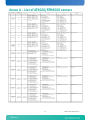
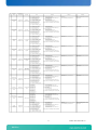
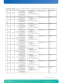
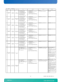
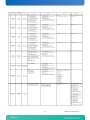
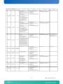
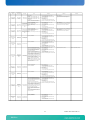
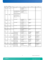
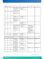
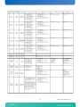
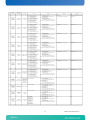
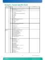
Sens
or ID
39
40
41
42
43
44
45
Sensor Name
/ Entity (ID)
FRU0 Power
/ PICMG Front Board
(160.96 )
FRU1 Power
/ PICMG Front Board
(160.96 )
FRU2 Power
/ PICMG Front Board
(160.96 )
FRU3 Power
/ PICMG Front Board
(160.96 )
Board Reset
/ PICMG Front Board
(160.96 )
EventRcv ComLost
/ PICMG Front Board
(160.96 )
IPMI Watchdog
/ PICMG Front Board
(160.96 )
Event/Reading Type
(Class and Code)
/ Sensor Type (Code)
(Threshold 0x01)
/ Other ( 0x0b)
(Threshold 0x01)
/ Other ( 0x0b)
(Threshold 0x01)
/ Other ( 0x0b)
(Threshold 0x01)
/ Other ( 0x0b)
(Discrete 0x6f)
/ OEM Board Reset (
0xc4)
Description
FRU 0 Power
consumption in watts
FRU 1 Power
consumption in watts
FRU 2 Power
consumption in watts
FRU 3 Power
consumption in watts
Board reset type and
sources
Offset
IPMB0 Link State
/ PICMG Front Board
(160.96 )
Reading that triggered the event, FFh or not present if
unspecified.
Do not confuse reading with Threshold Value
threshold value that triggered event, FFh or not
present if unspecified. If present, Event Data 2
must be present
Reading that triggered the event, FFh or not present if
unspecified.
Do not confuse reading with Threshold Value
threshold value that triggered event, FFh or not
present if unspecified. If present, Event Data 2
must be present
Reading that triggered the event, FFh or not present if
unspecified.
Do not confuse reading with Threshold Value
threshold value that triggered event, FFh or not
present if unspecified. If present, Event Data 2
must be present
FFh
FFh
00h (bit 0): State Deasserted
01h (bit 1): State Asserted
FFh
FFh
The Event Data 2 field for this command can be used to
provide
an event extension code, with the following definition:
FFh
bit[7:4]: interrupt type
0h = none
1h = SMI
2h = NMI
3h = Messaging Interrupt
Fh = unspecified
all other = reserved
bit[3:0]: timer use at expiration:
0h = reserved
1h = BIOS FRB2
2h = BIOS/POST
3h = OS Load
4h = SMS/OS
5h = OEM
Fh = unspecified
all other = reserved
bit[7:4] = Ah (OEM code in Event Data 2, OEM code in Event Data 3) bit[7:4] = Channel Number. For AdvancedTCA®, this will
bit[3:0] = Offset
typically be 0h to indicate IPMB-0
00h – IPMB-A disabled, IPMB-B disabled
bit[3:0] = Reserved
01h – IPMB-A enabled, IPMB-B disabled
02h – IPMB-A disabled, IPMB-B enabled
03h – IPMB-A enabled, IPMP-B enabled
IPMB-0 fault detection
sensor
20
AN09004
Data Byte 3
threshold value that triggered event, FFh or not
present if unspecified. If present, Event Data 2
must be present
[7:6] - 00b = unspecified byte 2
01b = previous state and/or severity in byte 2
10b = OEM code in byte 2
11b = sensor-specific event extension code in byte 2
Detects communication
(Discrete 0x03)
[5:4] - 00b = unspecified byte 3
/ Cable / Interconnect ( with the event receiver
01b = reserved
(ShMc) has been lost
0x1b)
10b = OEM code in byte 3
11b = sensor-specific event extension code in byte 3
[3:0] - Offset from Event/Reading Code for discrete event state
00h (bit 0): Timer expired, status only (no action, no [7:6] - 00b = unspecified byte 2
interrupt)
01b = previous state and/or severity in byte 2
01h (bit 1): Hard Reset
10b = OEM code in byte 2
02h (bit 2): Power Down
11b = sensor-specific event extension code in byte 2
03h (bit 3): Power Cycle
[5:4] - 00b = unspecified byte 3
04h-07h (bit[4:7]): reserved
01b = reserved
08h (bit 8): Timer interrupt
10b = OEM code in byte 3
11b = sensor-specific event extension code in byte 3
[3:0] - Offset from Event/Reading Code for discrete event state
(Discrete 0x6f)
IPMI Watchdog
/ Watchdog ( 0x23)
(payload watchdog)
(Discrete 0x6f)
/ PICMG IPMB0 Link
State ( 0xf1)
Data Byte 2
Reading that triggered the event, FFh or not present if
unspecified.
Do not confuse reading with Threshold Value
00h (bit 0): IPMB-A disabled, IPMB-B disabled
01h (bit 1): IPMB-A enabled, IPMB-B disabled
02h (bit 2): IPMB-A disabled, IPMB-B enabled
03h (bit 3): IPMB-A enabled, IPMP-B enabled
46
Data Byte 1
Threshold Values:
[7:6] - 00b = unspecified byte 2
00h : Lower Non-critical - going low
01b = trigger reading in byte 2
01h : Lower Non-critical - going high
10b = OEM code in byte 2
02h : Lower Critical - going low
11b = sensor-specific event extension code in byte 2
03h : Lower Critical - going high
[5:4] - 00b = unspecified byte 3
04h : Lower Non-recoverable - going low
01b = trigger threshold value in byte 3
05h : Lower Non-recoverable - going high
10b = OEM code in byte 3
06h : Upper Non-critical - going low
11b = sensor-specific event extension code in byte 3
07h : Upper Non-critical - going high
08h : Upper Critical - going low
Bit [3:0] = Offset from Event/Reading Code for threshold event.
09h : Upper Critical - going high
0Ah : Upper Non-recoverable - going low
0Bh : Upper Non-recoverable - going high
Threshold Values:
[7:6] - 00b = unspecified byte 2
00h : Lower Non-critical - going low
01b = trigger reading in byte 2
01h : Lower Non-critical - going high
10b = OEM code in byte 2
02h : Lower Critical - going low
11b = sensor-specific event extension code in byte 2
03h : Lower Critical - going high
[5:4] - 00b = unspecified byte 3
04h : Lower Non-recoverable - going low
01b = trigger threshold value in byte 3
05h : Lower Non-recoverable - going high
10b = OEM code in byte 3
06h : Upper Non-critical - going low
11b = sensor-specific event extension code in byte 3
07h : Upper Non-critical - going high
Bit [3:0] = Offset from Event/Reading Code for threshold event.
08h : Upper Critical - going low
09h : Upper Critical - going high
0Ah : Upper Non-recoverable - going low
0Bh : Upper Non-recoverable - going high
00h (bit 0): Push Button
[7:6] - 00b = unspecified byte 2
01h (bit 1): HWPower: Power error
01b = previous state and/or severity in byte 2
02h (bit 2): Unknown: Unknown PCI reset
10b = OEM code in byte 2
03h (bit 3): HwWatchDog: Hardware watchdog /
11b = sensor-specific event extension code in byte 2
IpmC Watchdog
[5:4] - 00b = unspecified byte 3
04h (bit 4): SoftReset: Soft reset
01b = reserved
05h (bit 5): WarmReset: Warm Reset
10b = OEM code in byte 3
06h (bit 6): ColdReset: Software generated cold reset
11b = sensor-specific event extension code in byte 3
07h (bit 7): IpmiCommand: Reset trigged by
[3:0] - Offset from Event/Reading Code for discrete event state
IpmiCommand chassis command fru control
08h (bit 8): Setup Reset: Cmos Setup generated
reset
09h (bit 9): PowerUpReset: Reset generated on
power up
0A-0Dh (bit 10-13): reserved
0Eh (bit 14): Shadow Reset
bit[7] – IPMB B Override State
0b = Override state, bus isolated
1b = Local Control state – IPM Controller
determines state of bus.
bit[6:4] = IPMB B Local Status
0h = No Failure. Bus enabled if no override in
effect.
1h = Unable to drive clock HI
2h = Unable to drive data HI
3h = Unable to drive clock LO
4h = Unable to drive data LO
5h = Clock low timeout
6h = Under test (the IPM Controller is
attempting to determine if it is causing a bus
hang)
7h = Undiagnosed Communications Failure
bit[3] – IPMB A Override Status
0b = Override status, bus isolated
1b = Local Control state – IPM Controller
determines state of bus.
bit[2:0] = IPMB A Local Status
0h = No Failure. Bus enabled if no override in
effect.
1h = Unable to drive clock HI
2h = Unable to drive data HI
3h = Unable to drive clock LO
4h = Unable to drive data LO
5h = Clock low timeout
6h = Under test (the IPM Controller is
attempting to determine if it is causing a bus
hang)
7h = Undiagnosed Communications Failure
AT8020: Sensor User Guide v1.0