1
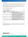
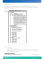
Byte 2: Provides information on the sensor Byte 3: For “Threshold” based sensor: Indicates were the reading stands against the threshold values. For “Discrete” sensors: Indicates which sensor offsets (states) are asserted for offset 00h to 07h. Byte 4: For “Threshold” based sensor: 80h (since bit 7 is always 1b) For “Discrete” sensors: Indicates which sensor offsets (states) are asserted for offset 08h to 14h. NOTE: Sensors have a reading mask which is “OEM” defined. This is used to ignore unused states during reading. Therefore, if a state that should be asserted is not read, the “Reading Mask” should be verified. Event Data When a sensor changes state, an “Event Message” is sent to the SEL only if the “Event Mask” indicates that the new state must generate an event. The “Event Data” contains 3 bytes where only the first byte is used. The signification of these bytes is listed in “Annex A” for every sensors implemented on the AT8020 and RTM8020. Entity “An Entity ID is a standardized numeric code that is used in SDRs to identify the types of physical entities or FRUs in the system”5 In the case of the AT8020, up to 4 entities can be present: - FRU0 PICMG Front Board (the board itself) - FRU1 PICMG AdvancedMC Module (AMC Bay 1) - FRU2 PICMG AdvancedMC Module (AMC Bay 2) - FRU3 PICMG Rear Transition Module (RTM) 5 IPMI v2.0 Section 39, p:488 8 AN09004 AT8020: Sensor User Guide v1.0