1
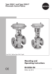
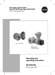
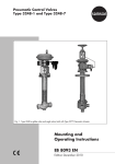
Type 3310/AT and Type 3310/3278
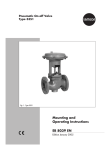
Pneumatic Control Valves
Type 3310 Segmented Ball Valve
Fig. 1 · Type 3310/3278 with positioner
Fig. 2 · Type 3310/AT
Mounting and
Operating Instructions
EB 8222 EN
Edition August 2013
Contents
Contents
Page
1
Design and principle of operation. . . . . . . . . . . . . . . . . . . . 4
2
2.1
2.1.1
2.1.2
2.2
Installation . . . . . . . . . .
Assembling valve and actuator
Type 3310-SRP . . . . . . . .
Type 3310/3278 . . . . . . .
Mounting position. . . . . . .
2.3
Loading pressure connection . . . . . . . . . . . . . . . . . . . . . . 8
3
3.1
Operation . . . . . . . . . . . . . . . . . . . . . . . . . . . . . . . 9
Changing the fail-safe action . . . . . . . . . . . . . . . . . . . . . . 9
4
4.1
Maintenance – Replacing parts . . . . . . . . . . . . . . . . . . . . . 9
Replacing the packing . . . . . . . . . . . . . . . . . . . . . . . . . 10
4.2
Replacing the seat ring. . . . . . . . . . . . . . . . . . . . . . . . . 10
4.3
Replacing the segmented ball, shafts and bearings . . . . . . . . . . . 12
5
Changing the characteristic . . . . . . . . . . . . . . . . . . . . . . 14
6
6.1
Tools and torques . . . . . . . . . . . . . . . . . . . . . . . . . . . 15
Special tools. . . . . . . . . . . . . . . . . . . . . . . . . . . . . . 15
6.2
6.2.1
Tightening torques . . . . . . . . . . . . . . . . . . . . . . . . . . . 16
Flange bolts . . . . . . . . . . . . . . . . . . . . . . . . . . . . . . 16
7
Description of nameplate . . . . . . . . . . . . . . . . . . . . . . . 16
8
Accessories . . . . . . . . . . . . . . . . . . . . . . . . . . . . . . 19
9
Customer inquiries . . . . . . . . . . . . . . . . . . . . . . . . . . 20
2
EB 8222 EN
.
.
.
.
.
.
.
.
.
.
.
.
.
.
.
.
.
.
.
.
.
.
.
.
.
.
.
.
.
.
.
.
.
.
.
.
.
.
.
.
.
.
.
.
.
.
.
.
.
.
.
.
.
.
.
.
.
.
.
.
.
.
.
.
.
.
.
.
.
.
.
.
.
.
.
.
.
.
.
.
.
.
.
.
.
.
.
.
.
.
.
.
.
.
.
.
.
.
.
.
.
.
.
.
.
6
6
6
7
8
Safety instructions
General safety instructions
4 The control valve may only be mounted, started up or serviced by fully trained
and qualified personnel, observing the accepted industry codes and practices.
Make sure employees or third persons are not exposed to any danger.
All safety instructions and warnings in these mounting and operating instructions, particularly those concerning installation, start-up and maintenance,
must be observed.
4 The control valves fulfill the requirements of the European Pressure Equipment
Directive 97/23/EC. Valves with a CE marking have a declaration of conformity that includes information about the applied conformity assessment procedure. The declaration of conformity is available on request.
4 For appropriate operation, make sure that the control valve is only used in
areas where the operating pressure and temperatures do not exceed the operating values which are based on the valve sizing data submitted in the order.
The manufacturer does not assume any responsibility for damage caused by
external forces or any other external influence! Any hazards which could be
caused in the control valve by the process medium, operating pressure, signal
pressure or by moving parts are to be prevented by taking appropriate
precautions.
4 Proper shipping and appropriate storage are assumed.
NOTICE
4 For installation and maintenance work on the valve, make sure the relevant
4
section of the pipeline is depressurized and, depending on the process medium, drained as well. If necessary, allow the control valve to cool down or
warm up to reach ambient temperature prior to starting any work on the
valve.
Prior to performing any work on the valve, make sure the supply air and control signal are disconnected or blocked to prevent any hazards that could be
caused by moving parts.
EB 8222 EN
3
Design and principle of operation
1
Design and principle of operation
The pneumatic control valve consists of the
Type 3310 Segmented Ball Valve and either
the Pfeiffer Type AT or the SAMSON
Type 3278 Pneumatic Rotary Actuator.
The control valve is used for both throttling
and on/off services in process engineering
and plants with industrial requirements.
It is suitable for liquids, vapors and gases
within a temperature range of –29 to
220 °C and for pressure rating Class 150
and 300.
The segmented ball valve in valve sizes
NPS 1 to 12 is available with a soft-seated
or metal-seated ball. A code number on the
nameplate located on the valve body indicates which type of seal is used.
The process medium flows through the valve.
The signal pressure acting on the rotary actuator determines the position (opening angle) of the segmented ball (8) and therefore
the flow rate across the open area between
the segmented ball and valve body (1).
The actuator motion is transmitted to the
segmented ball valve by a shaft with square
or key drive.
The valve shaft (4) is sealed by a self-adjusting PTFE V-ring packing (2.3).
4
EB 8222 EN
Fail-safe action:
The fail-safe action of the control valve,
which becomes effective when the supply air
(signal pressure) fails, is determined in
Type 3310/AT (Type SRP single-acting version) by the version used and in
Type 3310/3278 by how the pneumatic actuator is mounted to the valve.
Fail-close
The actuator springs close the valve when
the signal pressure is reduced or the supply
air fails.
When the signal pressure increases, the
valve is opened, acting against the spring
force.
Fail-open
The actuator springs open the valve when
the signal pressure is reduced or the supply
air fails.
When the signal pressure increases, the
valve is closed, acting against the spring
force.
The double-acting Type DAP Rotary Actuator has no springs. A defined final position
is not reached when the supply air fails.
Design and principle of operation
Pfeiffer Type AT Actuator
SAMSON Type 3278 Actuator
12.2
12 12.1
13.2 13.1
3.1
3
2.3
2.2
2
2.1
2.4
2.5
2.6
2.7
4
4.1
4.3
1
A
11.3
11
11.4
11.5
11.6
11.7
11.8
11.1
11.2
5.4
5.3
5.1
5.2
5
10
10.1 10.3 10.2
Detail A = See Fig. 5 for seal
Fig. 3 · Sectional drawing
8
1
2
2.1
2.2
2.3
2.4
2.5
2.6
2.7
3
3.1
4
4.1
4.2
4.3
5
5.1
5.2
5.3
5.4
13
4.2
4
Body
Packing gland
Bearing bushing
Screws
Packing
Washer
Spring
Disk
Spacer
Yoke
Screws
Shaft
Bearing bushing
Key
Retaining ring
Support shaft
Bearing bushing
Threaded pin
Clamping bolt
Locking pins
8
10
10.1
10.2
10.3
11
11.1
11.2
11.3
11.4
11.5
11.6
11.7
11.8
12
12.1
12.2
13
13.1
13.2
Segmented ball
Bottom flange
Flange gasket
Flange ring
Flange bolts
Retainer
Screw
Washer
Flat gasket
Washer
Metal tubular seal
Metal seat ring
Support ring
PTFE seat ring
Type AT Actuator
Stop screw
Stop screw
Type 3278 Actuator
Stop screw
Stop screw
EB 8222 EN
5
Installation
2
Installation
2.1
Assembling valve and actuator
2.1.1 Type 3310-SRP
If the valve and actuator have not been assembled by the manufacturer, proceed as
follows:
Note: In the standard actuator version (SRP
= single-acting with spring-return), the
spring-return mechanism is designed to
close clockwise when there is no signal pressure.
Should another direction of rotation or a
double-acting actuator (DAP = double-acting without spring-return) be required, this
must be specified on ordering the actuator.
Table 1
Fail-safe action
Springs
Characteristic
Fail-close
Clockwise
Equal percentage
Fail-close
Counterclockwise
Linear
Fail-open
Clockwise
Linear
Fail-open
Counterclockwise Equal percentage
The rotary actuator with a square drive can
be placed either vertically or horizontally at
a 90° angle to the segmented ball valve.
Fail-close valve
1. Place the segmented ball (8) of the valve
in the closed position (0° angle of rotation).
6
EB 8222 EN
2. Fasten the yoke (3) to the flange of the
valve shaft using two or four screws (depending on the valve size).
3. If necessary, place the shaft adapter on
the valve shaft, then slide the actuator
over the adapter or valve shaft (4) and
fasten it onto the yoke with four screws.
4. Adjust the stop screws (12.1 or 12.2 depending on the direction of rotation) to
close the valve completely. Additionally,
align the markings on the shaft and
packing flange.
5. Secure the position of the stop screw
with its lock nut.
6. Apply a signal pressure to the loading
pressure connection which corresponds
to the number of springs in the actuator
(see actuator nameplate).
7. Adjust the other stop screw so that the
segmented ball stops at 90° angle of rotation.
8. Secure the position of the stop screw
with its lock nut.
Fail-open valve
1. Place the segmented ball (8) of the valve
in the open position (90° angle of rotation).
2. Fasten the yoke (3) to the flange of the
valve shaft using two or four screws (depending on the nominal size).
3. If necessary, place the shaft adapter on
the valve shaft, then slide the actuator
over the adapter or valve shaft (4) and
fasten it onto the yoke with four screws
(3.1).
4. Adjust the stop screw (12.1 or 12.2 depending on the direction of rotation) so
Installation
5.
6.
7.
8.
that the valve is fully open at 90°.
Additionally, align the markings on the
shaft and packing flange.
Secure the position of the stop screw
with its lock nut.
Apply a signal pressure to the loading
pressure connection which corresponds
to the number of springs in the actuator
(see actuator nameplate).
Adjust the other stop screw so that the
segmented ball is fully closed. To do this,
align the markings on the shaft and
packing flange.
Secure the position of the stop screw
with its lock nut.
2.1.2 Type 3310/3278
If the valve and actuator have not been assembled by the manufacturer, proceed as
follows to mount the actuator onto the body
flange 1 or 2 depending on the characteristic and fail-safe position:
'1' or '2' is cast onto the corresponding side
of the valve body.
Table 2
Fail-safe action
Characteristic
Body flange
Fail-close
Equal percentage
2
Fail-close
Linear
1
Fail-open
Equal percentage
1
Fail-open
Linear
2
The rotary actuator can be placed as required to suit the on-site conditions either vertically or horizontally at a 90° angle to the
segmented ball valve.
Fail-close valve
1. Unscrew both stop screws (13.1 and
13.2) at the rotary actuator, then screw
back in the stop screw (13.2) until the
actuator shaft's grooves are aligned horizontally or vertically to the actuator
axis.
2. Place the segmented ball (8) of the valve
in the closed position (0° angle of rotation).
3. Fasten the yoke (3) to the flange of the
valve shaft with two or four screws depending on the nominal size.
4. Slide the actuator with the actuator shaft
over the valve shaft (4) and screw down
to the yoke (3) with four screws.
5. Unscrew the stop screw (13.2) again.
6. Adjust the stop screw (13.2) so that the
valve is fully closed. Additionally, align
the markings on the shaft and packing
flange.
7. Apply a supply pressure required for the
spring range (see actuator nameplate) to
the loading pressure connection to open
the valve.
8. Screw back in the stop screw (13.1) until
the valve reaches its open position (90°
angle of rotation).
9. Secure both stop screws with their lock
nuts.
Fail-open valve
1. Unscrew both stop screws (13.1 and
13.2) at the rotary actuator, then screw
back in the stop screw (13.2) until the
actuator shaft's grooves are aligned hor-
EB 8222 EN
7
Installation
izontally or vertically to the actuator
axis.
2. Place the segmented ball (8) of the valve
in its open position (90° angle of rotation).
3. Fasten the yoke (3) to the flange of the
valve shaft with two or four screws depending on the nominal size.
4. Slide the actuator over the valve shaft (4)
and screw tight to the yoke (3) with four
screws.
5. Unscrew the stop screw (13.1) again.
6. Apply a supply pressure required for the
spring range (see actuator nameplate) to
the loading pressure connection to close
the valve.
7. Adjust the stop screw (13.1) until the
valve is fully closed by the segmented
ball. In addition, align the markings on
shaft and packing flange
8. Disconnect supply pressure.
9. Screw back in the stop screw (13.2) until
the segmented ball stops at 90° angle of
rotation in the open position.
10. Secure both stop screws with their lock
nuts.
2.2
Mounting position
however, the following points regarding the
direction of flow must be observed:
Install the valve in the pipeline so that the
lower half of the segmented ball opens into
the flow. This helps avoid dirt deposits from
accumulating which could prevent the valve
from opening. The direction of medium flow
into the convex of the ball also prevents the
medium from collecting unnecessarily in the
shaft bearings.
The standard direction of flow (into the convex face) is indicated by the manufacturer
by an arrow on the valve body.
Should the direction of flow be reversed,
e.g. required for abrasive media, it is necessary to indicate the reversed direction by using the arrow plate and the two slotted pins
included in the scope of delivery. Using this
direction of flow causes the pressure of the
process medium to constantly act on the
packing. On tightening the flange bolts,
make sure that an even pressure is exerted
on the flat gaskets.
2.3
Loading pressure connection
The loading pressure connection of rotary
actuators is a G 18 female thread port for
small actuators and a G ¼ port for larger
actuators.
Note: Prior to installing the valve into the
pipeline, place it in the CLOSED position to
allow the seat to be centered properly with
the segmented ball.
The connection allows in compliance with
VDE/VDE 3845 guidelines the connection
of a solenoid valve, e.g. Type 3963, or a
limit switch with or without a solenoid valve
(Type 3776/3777).
The control valve can be installed into a
pipeline either vertically or horizontally,
Accessories are available for the connection
of SAMSON positioners.
8
EB 8222 EN
Operation
3
Operation
3.1
Changing the fail-safe action
The fail-safe action can be changed in the
Type 3278 Actuator after delivery from
fail-close to fail-open and vice versa.
To do this, the attachment side of the rotary
actuator must be changed (see the table on
page 7).
The position of pistons in the Type SRP Actuator must be reversed.
Note: Refer to the mounting and operating
instructions of the rotary actuator used for
further details about, for example, changing
the spring range to obtain other actuator
torques.
4
Maintenance – Replacing
parts
The control valve is subject to natural wear
especially at the seat, segmented ball and
packing. Depending of the application conditions that prevail, the valve must be inspected at appropriately scheduled intervals
to prevent any problems before they occur.
If any leaks occur to the atmosphere, the
packing may be leaking.
If the valve does not shut-off properly, this
may be because tight shut-off is prevented
by dirt or other impurities between the seat
ring and segmented ball or because the
seating surfaces have been damaged.
If you intend to remove parts to clean them,
first mark the position of the seat ring (11.8)
in the body for a valve with soft-seated ball.
This will help you to replace the seat ring in
its correct position on reassembling the
valve.
Proceed as described in section 4.2 to replace the seat ring (11.6 or 11.8) with new
ones.
CAUTION!
Before removing parts from the
valve, remove the valve from the
pipeline. To proceed, first relieve the
corresponding plant section of pressure and drain it. Let the plant section cool down, if necessary.
Note: Prior to performing any work
on the valve body, remove the actuator.
EB 8222 EN
9
Maintenance – Replacing parts
Removing the actuator:
1. Unscrew the two or four screws on the
flange of the valve shaft and pull off the
actuator together with the yoke (3).
4.1
Replacing the packing
The valves in NPS 1 to 12 are fitted with a
V-ring packing.
1. Unscrew the screws (2.2) and take off
packing flange (2) with the bearing
bushing (2.1).
2. Remove all packing parts from the packing chamber using a suitable tool. Clean
them thoroughly.
3. Renew packing (2.3), then push new
packing parts over the shaft (4) into the
packing chamber.
4. Push the packing flange (2) together with
bearing bushing (2.1) onto the shaft (4).
Fasten the packing flange using the
screws (2.2).
4.2
Replacing the seat ring
1. Remove both anchoring screws (11.1)
with washers (11.2).
2. Take out the retainer (11) together with
the flat gasket (11.3).
If you are unable to remove the retainer,
use the special tool listed in Table 3.
Soft-seated version:
3. Remove the support ring (11.7) and the
seat ring (11.8).
Metal-seated version:
3. Remove in sequence any washer(s)
(11.4), the metal tubular seal (11.5),
seat ring (11.6) and the washers (11.4).
4
2.2
2
2.1
Reassembly
2.3
To reassemble, proceed in the reverse order.
Special tools are not necessary.
2.4
2.5
2.6
2.7
Fig. 4 · Packing
10
EB 8222 EN
The retainer (11) can be pressed into the
body using, for example, a blank flange, by
tightening the flange bolts accordingly. Prior
to this, it is absolutely necessary to place the
valve in the closed position to center the seat
ring and segmented ball.
Maintenance – Replacing parts
Metal-seated version:
Note: Check the friction torque (breakaway
torque) needed to open the valve according
to the table on page 15.
Change the number of washers (11.4) used.
If necessary, omit the bottom washer on the
valve body side.
If the friction torque is different from the
torque specified in the table, proceed as follows:
Soft-seated version:
Turn the segmented ball clockwise by 360°
in the valve body two or three times to let
the seal adapt itself.
1
8
11
11.1
11.2
11
11.7
Soft-seated version:
11.7 Support ring
11.8 PTFE seat ring
11
11.5
11.6
11.4
11.8
1
Soft seal
1
Metal-seated version:
11.4 Washer
11.5 Metal tubular seal
11.6 Metal seat ring
Metal seal
1
11
Body
Segmented ball
Retainer
Screw
Washer
8
11.1
11.2
11.3
Fig. 5 · Seat seal
EB 8222 EN
11
Maintenance – Replacing parts
4.3
Replacing the segmented
ball, shafts and bearings
Note: No clearance may exist between the
segmented ball and shafts. Therefore, the
shafts need to be replaced as well when the
segmented ball is replaced with a new one.
Furthermore, the bearing bushings and seat
rings as well as the ring and gasket on the
bottom flange need to be renewed as well.
1. Unscrew both bolts (10.3) and lift off
bottom flange (10) together with the ring
(10.2). Remove the flange gasket (10.1).
2. Unscrew the threaded pin (5.2) out of
the shaft and remove the clamping bolt
(5.3). Make sure that the locking pins
(5.4) do not get lost.
Press out the support shaft. If this is not
possible, screw in a screw with a washer
(see table listing special tools) in place of
the threaded pin. Turning the screw
against the washer loosens the support
shaft.
3. Pull the bearing bushing (5.1) out of the
body.
4. Unthread screws (2.2) and lift off the
packing flange (2) together with the
bearing bushing (2.1).
5. Use snap ring pliers to pull the retaining
ring (4.3) off the shaft and pull the shaft
out of the body using disassembling tool.
6. Remove all packing parts with the appropriate tool from the packing space,
and clean packing space thoroughly.
7. Remove the lower bearing bushing (4.1).
12
EB 8222 EN
8. Take the segmented ball out of the body.
For valves in NPS 1, 1 ½ and 2, the
segmented ball must be removed from
the retainer side. Proceed as described
in section 4.2, dismantling first the retainer and the seat ring parts.
Reassembly
We recommend purchasing the assembly
tools listed in Table 3 for reassembling the
valve.
To assemble the valve, proceed in the reverse order as described in disassembly.
Observe the tightening torques of the bolts
for the packing flange and bottom flange
listed in Table 3.
On inserting the shaft (4) into the body and
the segmented ball, make sure that the shaft
is aligned correctly with the segmented ball
(the red marking on the shaft must be positioned at a right angle to the pipeline when
the valve is closed).
1. Insert the segmented ball (8) into the
valve body.
2. Push first the bearing bushing (4.1) into
the body, then align the shaft (4) and
use an assembling tool to press the bearing bushing into the segmented ball.
3. Use the part of the tool that is in the
bearing of the support shaft to slide the
segmented ball (8) onto the shaft (4)
and attach the retaining ring (4.3).
4. Insert the locking pins (5.4) into the holes
of the support shaft (5), then position the
complete support shaft (parts 5, 5.2, 5.3
and 5.4) on the bearing bushing (5.1)
Maintenance – Replacing parts
and use the packing flange (2) to press
them in.
5. Align the segmented ball (8) centrally.
6. Screw the threaded pin (5.2) against the
clamping bolt (5.3) to obtain a
force-locking connection between the
support flange and segmented ball.
7. Mount the packing with spacer (2.7),
washer (1.6), spring (2.5), thrust washer
(2.4), packing (2.3) and flange (2).
1
4
4.1
4.3
5
5.1
Body
Shaft
Bearing bushing
Retaining ring
Support shaft
Bearing bushing
1
5.2
5.3
5.4
8
10
10.1
11
Note: Check the friction torque (breakaway
torque) needed to open the valve according
to Table 3.
Proceed as described in section 4.2 if the
torque is different than specified.
Threaded pin
Clamping bolt
Locking pins
Segmented ball
Bottom flange
Flange gasket
8
11.1
11.2
10.2
10.3
11
11.1
11.2
11.3
Flange ring
s
Retainer
Screw
Washer
Flat gasket
11.3
10
10.1
10.2
10.3
5
5.1 5.2
5.3
5.4
4.3
4
4.1
Fig. 6 · Sectional drawing
EB 8222 EN
13
Changing the characteristic
5
Changing the characteristic
Changing the characteristic from equal percentage to linear and vice versa can be carried out by changing the actuator's direction
of rotation.
See Table 1 and 2.
14
EB 8222 EN
Tools and torques
6
Tools and torques
6.1
Special tools
Table 3 · Special tools
Extracting tool
for retainer (11)
NPS
Crossbeam
Extracting tool
for support shaft (5)
Tool to mount and remove the shaft
Press tool for
support shaft
Flange
Press tool for
actuator shaft
Order no.
1
1
1
1281-0011
2
1281-0012
2
1281-0013
3
1281-0014
4
1281-0015
6
1281-0016
8
1281-0017
10
12
1281-0018
Adapter
for torque wrench
1, 1
NPS
1
2
, 2, 3
4, 6
8, 10
12
1281-0007
1281-0019
1281-0026
1281-0008
1281-0023
1281-0020
1281-0009
1281-0027
1281-0021
1281-0024
1281-0010
1281-0028
1281-0022
1281-0025
Shaft with square drive
Shaft with key drive
1281-0029
1281-0032
1281-0030
1281-0031
1281-0033
EB 8222 EN
15
Tools and torques
6.2
Tightening torques
Table 4
Valve size NPS
Tightening torque in Nm
Screws (2.2) on packing flange
Bolts (10.3) on bottom flange
1
1
2
3
4
6
8
10
12
35
35
35
35
35
35
60
60
60
1
1
2
3
4
6
8
10
12
8
9
10
12
11
14
19
24
40
50
70
100
100
170
155
260
155
260
1
2
Friction torques
Valve size NPS
Friction torque
to open the valve [Nm]
Metal seal
Soft seal
1
2
6.2.1 s
Table 5 · ANSI version
NPS
1
11 2
2
3
4
6
8
16
EB 8222 EN
Class
s
(quality 8.8)
”
Min. tightening torque
in Nm
35
150
4x
1
300
4x
5
”
45
150
4x
1
2”
45
300
4 x 3 4”
65
150
4x
”
90
300
8 x 5 8”
45
150
4x
”
125
300
8 x 3 4”
65
150
8 x 5 8”
80
5
5
2
8
8
8
300
8x
”
80
150
8 x 3 4”
125
300
12 x 3 4”
80
150
8x
”
165
300
12 x 7 8”
125
3
3
4
4
Tools and torques
NPS
10
12
Class
s
(quality 8.8)
150
12 x 7 8”
155
300
16 x 1”
135
150
12 x 7 8”
155
300
16 x
”
125
9
8
Min. tightening torque
in Nm
Table 6 · DIN version
DN
PN
Flange bolts
(quality 8.8)
Min. tightening torque
in Nm
25
10/40
4 x M12
40
40
10/40
4 x M16
55
50
10/40
4 x M16
75
10/16
8 x M16
55
25/40
8 x M16
55
10/16
8 x M16
70
25/40
8 x M20
85
10/16
8 x M20
125
25/40
8 x M24
150
10
8 x M20
165
16
12 x M20
110
25
12 x M24
135
40
12 x M27
150
10
12 x M20
140
16
12 x M24
165
25
12 x M27
185
40
12 x M30
205
10
12 x M20
140
16
12 x M24
165
25
16 x M27
140
40
16 x M30
165
80
100
150
200
250
300
EB 8222 EN
17
Description of nameplate
7
Description of nameplate
SAMSON
4
PN 6
Kvs
3310 - 1
5
3-
7
DN 3
2
8
9
10
90°
11
Fig. 7 · Nameplate
The nameplate contains all details to identify
the valve:
1
2
3
4
Type designation
Serial number
Valve size NPS/DN …
Seat/ball seal
ME Metal seal
PT
PTFE
PK
PEEK 450G Victrex®
PK1 PEEK 450FC30 Victrex®
5 Body material
6 Pressure rating Class/PN …
7 Flow coefficient KVS .../CV …
Characteristic
%
Equal percentage
LIN Linear
8 PED text
9 Notified body
10 Year of manufacture
11 Direction of flow and
maximum opening angle
18
EB 8222 EN
70°
Made in france
Accessories
8
Accessories
Table 7
NPS
Type AT Actuator
SRP/DAP
Connecting flange
DIN 3337
Mounting kit
Order no.
1
30
60
F05
1400-7316
11 2
60
100
F05
F07
1400-7316
1400-7317
2
60
100
150
F05
F07
F07
1400-7348
1400-7239
1400-7239
3
100
150
220
F07
F07
F10
1400-7239
1400-7239
1400-7732
4
220
300
450
F10
F10
F12
1400-7240
1400-7240
1400-7241
6
300
450
600
F10
F12
F12
1400-7240
1400-7241
1400-7241
8
600
900
1200
F12
F14
F14
1400-7755
1400-7243
1400-7243
10
900
1200
F14
F14
1400-7243
12
900
1200
F14
F14
1400-7243
Actuator cm²
Type 3278
Mounting kit
Order no.
1400-7251
160 (F07)
1400-7252
320 (F12)
1400-7255
EB 8222 EN
19
Customer inquiries
9
Customer inquiries
Should you have any questions regarding
the control valve, please submit the following details:
4 Order number
(mentioned on the nameplate)
4 Type, model number, valve size and
valve version
4 Pressure and temperature of the process
medium
4 Flow rate in m³/h
4 Bench range (spring range of the actuator)
4 Installation drawing
20
EB 8222 EN
Dimensions
Refer to the Data Sheet T 8222 EN for details about dimensions and weights.
EB 8222 EN
21
22
EB 8222 EN
EB 8222 EN
23
EB 8222 EN
2013-09
SAMSON AG · MESS- UND REGELTECHNIK
Weismüllerstraße 3 · 60314 Frankfurt am Main · Germany
Phone: +49 69 4009-0 · Fax: +49 69 4009-1507
Internet: http://www.samson.de