1
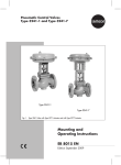
Type 3244-1 and Type 3244-7 Pneumatic Control Valves Type 3244 1 (left) and Type 3244-7 (right) Mounting and Operating Instructions EB 8026 EN Edition July 2014 Definition of signal words DANGER! Hazardous situations which, if not avoided, will result in death or serious injury WARNING! Hazardous situations which, if not avoided, could result in death or serious injury 2 NOTICE Property damage message or malfunction Note: Additional information Tip: Recommended action EB 8026 EN Contents 1 General safety instructions..............................................................................4 2 Design and principle of operation...................................................................6 3 Assembling valve and actuator.......................................................................8 1.1 Assembly and adjustment................................................................................8 4 Installation.....................................................................................................9 1.2 Mounting position...........................................................................................9 1.3 Arrangement of the valve................................................................................9 1.4 Signal pressure line.........................................................................................9 1.5 Strainer, bypass..............................................................................................9 1.6 Test connection.............................................................................................10 5 Operation....................................................................................................12 6 Maintenance – Replacing parts.....................................................................12 1.1 Standard valve version..................................................................................13 1.1.1Packing........................................................................................................13 1.1.2 Seat and plug...............................................................................................14 1.2 Valve with insulating section or bellows seal....................................................14 1.2.1Packing........................................................................................................14 1.2.2 Seat and plug...............................................................................................16 1.2.3 Metal bellows...............................................................................................17 1.2.4Assembly.....................................................................................................17 7 Material number..........................................................................................18 8 Description of nameplates.............................................................................18 9 Customer inquiries.......................................................................................19 EB 8026 EN 3 General safety instructions 1 General safety instructions WARNING! −−The control valves are to be mounted, started up or serviced by fully trained and qualified personnel only; the accepted industry codes and practices are to be observed. Make sure employees or third persons are not exposed to any danger. −−All safety instructions and warnings given in these mounting and operating instructions, particularly those concerning installation, start-up and maintenance, must be strictly observed. −−The control valves comply with the requirements of the European Pressure Equipment Directive 97/23/EC. Valves with a CE marking have a declaration of conformity which includes information about the applied conformity assessment procedure. The Declaration of Conformity is available on request. −−To ensure appropriate use, only use the valve in applications where the operating pressure and temperatures do not exceed the specifications used for sizing the valve at the ordering stage. The manufacturer does not assume any responsibility for damage caused by external forces or any other external factors. Any hazards that could be caused in the valve by the process medium, the operating pressure, the signal pressure or by moving parts are to be prevented by taking appropriate precautions. −−Proper shipping and storage are assumed. NOTICE −−For installation and maintenance, make sure the relevant section of the pipeline is depressurized and, depending on the process medium, drained as well. Depending on the field of application, allow the valve to cool down or warm up to reach ambient temperature before starting any work on it. −−When working on the valve, make sure that the pneumatic air supply as well as the control signal are disconnected to prevent any hazards caused by moving parts. −−Be particularly careful if the actuator springs of pneumatic control valves are preloaded. Such actuators are labeled correspondingly and can also be identified by three long bolts protruding from the bottom of the actuator. Before starting any work on the valve, relieve the compression from the preloaded springs. 4 EB 8026 EN General safety instructions Note: According to the ignition risk assessment performed in accordance with EN 13463-1: 2001, section 5.2, the non-electrical actuators and valves do not have their own potential ignition source even in the rare incident of an operating fault. As a result, they do not fall within the scope of Directive 94/9/EC. For connection to the equipotential bonding system, observe the requirements specified in section 6.3 of EN 60079-14: 2011 (VDE 0165 Part 1). Note: These Mounting and Operating Instructions are also valid for the Type 3246 Threeway Valve – Class 150 and 300 in conjunction with the Data Sheet T 8046-3 EN. EB 8026 EN 5 Design and principle of operation 2 Design and principle of operation The Type 3244-1 and Type 3244-7 Pneumatic Control Valves consist of the Type 3244 Three-way Valve and either a Type 3271 or Type 3277 Pneumatic Actuator. The modular design allows the actuators to be exchanged and an insulating section or metal bellows to be fitted to the standard valve version. Depending on the plug version, the threeway valve can be used either as a mixing or diverting valve (in DN 15 to 25, the plugs are identical). In mixing valves, the process media to be mixed enter at valve ports A and B. The combined flow exits the valve at port AB. In diverting valves, the process medium enters at the valve port AB and the partial flows exit at ports A and B. Fail-safe position Depending on how the compression springs are arranged in the actuator, the valve has two different fail-safe positions: Actuator stem extends When the pressure is relieved or the supply air fails, the springs cause port B (mixing valves) or port A (diverting valves) to close. The valve ports B or A are opened against the force of the springs when the signal pressure increases. Actuator stem retracts When the pressure is relieved or the supply air fails, the springs cause port B (mixing valves) or port A (diverting valves) to open. The valve ports B or A are closed against the force of the springs when the signal pressure increases. The flow rate from ports A or B to AB and vice versa depends on the cross-sectional area of flow between the seat (2.1, 2.2) and plug (3) and, as a result, on the position of the plug stem (6). The plug (3) is moved by a change in signal pressure acting on the diaphragm of the actuator. The plug stem (6) and actuator stem (8.1) are connected by the stem connector (7) and sealed by a spring-loaded PTFE ring packing (4.2). 6 EB 8026 EN Design and principle of operation 1.1 Nuts 5.2 Threaded bushing 1.2 Gasket 5.3 Travel indicator scale 2.1 Top seat 6 Plug stem 2.2 Bottom seat 6.1 Stem connector nut 3 Plug 6.2 Lock nut 3.1 Plug section 7 Stem connector 3.2 Screw 8 Actuator 4.1 Spring 8.1 Actuator stem 4.2 Packing 8.2 Nut 5 Valve bonnet Type 3277 Actuator 8 Type 3271 Actuator 8.1 5 8.2 8 5 5.3 8.2 8.1 7 6.1 1.1 6.2 1.2 7 6.1 6.2 1.1 5.2 1.2 4.2 4.1 6 AB A 6 2.1 3 2.2 3.1 2.1 B 3 2.2 A AB 3.2 Plug arrangement for diverting service DN 32 to 150 B Plug arrangement for mixing service, in DN 15 to 25 also for diverting service Fig. 1: Sectional drawings EB 8026 EN 7 Assembling valve and actuator 3 Assembling valve and actuator The basic pneumatic actuator can be replaced by a pneumatic actuator with additional handwheel or by an electric actuator. A pneumatic actuator (with or without handwheel) can be replaced by another pneumatic actuator in a different size. If the travel range of the actuator is larger than the travel range of the valve, the springs in the actuator are preloaded by SAMSON so that the travel ranges match. 3.1 Assembly and adjustment Proceed as follows if the valve and actuator have not been assembled by SAMSON or if the actuator is to be replaced by an actuator of another type or size: 1. Loosen the lock nut (6.2) and stem connector nut (6.1) on the valve. 2. Press the plug together with the plug stem firmly into the seat ring. Thread down the lock nut and stem connector nut. 3. Remove the clamps of the stem connector (7) and the ring nut (8.2) from the actuator (8). 4. Slide the ring nut over the plug stem. 5. Place the actuator onto the valve bonnet (5) and secure it with the ring nut (8.2). The lower value corresponds to the lower bench range value (0.2 bar) to be adjusted, whereas the upper value corresponds to the upper bench range value (1 bar). The fail-safe action "actuator stem extends" or "actuator stem retracts" is marked by FA or FE on the Type 3271 Actuator, and by a corresponding symbol on the nameplate of the Type 3277 Actuator. 7. For actuators with "actuator stem extends" fail-safe action, apply a signal pressure that corresponds to the lower bench range value (e.g. 0.2 bar) to the connection on the bottom diaphragm chamber. For actuators with "actuator stem retracts" fail-safe action, apply a signal pressure that corresponds to the upper bench range value (e.g. 1 bar) to the top diaphragm chamber connection. 8. Screw on the stem connector nut (6.1) by hand until it touches the actuator stem (8.1). Then turn it a further ¼ turn and secure this position with the lock nut (6.2). 9. Position clamps of the stem connector (7) and screw them tight. 10.Align the travel indicator (5.3) with the tip of the stem connector. 6. Read the bench range (or bench range with preloaded springs) and the actuator's fail-safe action from the actuator's nameplate (e.g. 0.2 to 1 bar and "actuator stem extends"). 8 EB 8026 EN Installation 4 Installation 4.2 Arrangement of the valve 4.1 Mounting position Install the valve as shown in Fig. 2 depending on whether it is to be used for mixing or diverting service. The valve can be mounted in any desired position. However, to avoid increase wear at the packing, install valves in DN 100 or larger in the upright position with the actuator on top. For valves fitted with an insulating section or bellows seal and for actuators weighing more than 50 kg, the actuator needs to be supported or suspended. NOTICE Install the valve free of stress. Pipeline routing To ensure that the control valve functions properly, the pipeline must be straight and without any manifolds or disturbances for a distance of at least 6 times the valve size (DN) upstream and downstream of the valve. Contact SAMSON if this distance cannot be observed. Flush the pipeline thoroughly before installing the valve. Note: Only insulate control valves with insulating section or bellows seal up to the bonnet flange of the valve body for medium temperatures below 0 °C and above 220 °C. Do not insulate valves mounted to comply with NACE MR0175 requirements. EB 8026 EN The installation examples apply to standard operation with fail-safe action "actuator stem extends" for heating applications and "actuator stem retracts" for cooling applications. Fail-safe position The valve shuts off the flow of the heating or cooling medium. The plug arrangement (i.e. either mixing or diverting valve) is indicated on a label attached to the valve body. In DN 15 to 25, the plug arrangement is the same for mixing and diverting valves. 4.3 Signal pressure line Connect the signal pressure line for valves with an actuator with "actuator stem extends" fail-safe action to the connection on the bottom diaphragm case, and for valves with an actuator with "actuator stem retracts" fail-safe action to the connection on the top diaphragm case. In the Type 3277 Actuator, the bottom signal pressure connection is located at the side of the yoke under the bottom diaphragm case. 4.4 Strainer, bypass We recommend installing a SAMSON Type 2 Strainer upstream of the valve, and upstream of both inlet ports in mixing valves. 9 Installation We recommend installing a shut-off valve both upstream of the strainer and downstream of the valve to ensure that the plant does not need to be shut down for maintenance. In addition, install a bypass line. 4.5 Test connection Versions with bellows seal (Fig. 4) fitted with a test connection (G 1/8) at the top flange allow the tightness of the bellows to be monitored. Particularly for liquids and vapors, we recommend installing a suitable leakage indicator, such as a contact pressure gauge, an outlet to an open vessel or an inspection glass. 10 EB 8026 EN Installation Mixing service Temperature control Q = constant Diverting service Flow control Q = 0 to 100 % Fail-safe action: FA = "Actuator stem extends", FE = "Actuator stem retracts" In heating applications with FA, the heating medium (flow) is shut off in the fail-safe position, in cooling applications with FE, cooling is maintained in the fail-safe position. Heating with mixing valve FA or cooling with mixing valve FE Installation in flow pipe A Flow pipe AB B Return flow pipe Flow pipe Installation in return flow pipe Flow pipe Return flow pipe AB A B Return flow pipe A AB B Flow pipe Return flow pipe AB A B Heating with diverting valve FA or cooling with diverting valve FE Installation in return flow pipe Flow pipe Flow pipe Return flow pipe Installation in flow pipe A AB B A AB B Flow pipe Return flow pipe Flow pipe A AB B Return flow pipe AB A B Return flow pipe Fig. 2: Typical installations EB 8026 EN 11 Operation 5 Operation WARNING! −−Before performing any work on the control valve, make sure the relevant plant section has been depressurized and, depending on the process medium, drained as well. −−When used at high temperatures, allow the plant section to cool down to ambient temperature. −−Valves are not free of cavities. Therefore, there might still be residual medium in the valve. This applies to valve versions with bellows seal or insulating section in particular. We recommend removing the valve from the pipeline. −−Before starting any work on the valve body, disconnect the signal pressure and remove the actuator. (e.g. reversing the operating direction etc.) Refer to the mounting and operating instructions of the pneumatic actuators: u EB 8310 EN for Type 3271 u EB 8311 EN for Type 3277 6 Maintenance – Replacing parts The control valve is subject to normal wear, especially at the seat, plug and packing. Depending on the operating conditions, check the valve at regular intervals to prevent possible failure before it can occur. External leakage can indicate that the packing is defective or the metal bellows is defective (in a version with a bellows seal). If the valve does not close tightly, tight shutoff may be impaired by dirt stuck between the seat and plug or by damaged facings. We recommend removing the parts, cleaning them, and, if necessary, replacing them with new ones. 12 Note: Suitable seat wrenches and special tools as well as the associated tightening torques are listed in the document u EB 029 EN. Contact your nearest SAMSON subsidiary or the SAMSON After-sales Service department for information on suitable lubricants. Removing the actuator from the valve Note: When removing an actuator with "actuator stem extends" fail-safe action from a valve, and especially an actuator with preloaded springs, apply a signal pressure that is slightly higher than the lower bench range value (see actuator nameplate) to the bottom signal pressure connection so that the ring nut (8.2) can be unscrewed. 1. Remove the stem connector (7) and unscrew the ring nut (8.2). EB 8026 EN Maintenance – Replacing parts 2. Remove the actuator from the valve bonnet. 6.1 Standard valve version 6.1.1 Packing 15.Loosely screw the lock nut (6.2) and stem connector nut (6.1) onto the plug stem. 16.Mount the actuator. Refer to section 3.1. 17.Adjust the upper and lower bench range values. See section 3.1. 1. Unscrew the lock nut (6.2) and stem connector nut (6.1) from the plug stem. 5.2 2. Unscrew the threaded bushing (5.2). 3. Remove body nuts (1.1). 4. Lift the valve bonnet (5) off the valve body over the plug stem. 5. Pull all the packing parts out of the packing chamber using a suitable tool. 6. Replace damaged parts. 4.2 4.1 4.2 4.3 5 5.2 6 Spring PTFE ring packing Washer Bonnet Threaded bushing Plug stem 4.3 4.1 7. Clean the packing chamber thoroughly. 8. Remove gasket (1.2). 9. Carefully clean the sealing faces in the valve body and on the bonnet. 10.Apply a suitable lubricant to all the packing parts and to the plug stem (6). 6 5 Fig. 3: Packing 11.Insert a new gasket (1.2) into the valve body. 12.Place the valve bonnet over the plug stem onto the valve body and secure it with nuts (1.1). 13.Carefully slide the packing parts (4.1, 4.3 and 4.2) over the plug stem into the packing chamber. Make sure you observe the proper order. 14.Screw in the threaded bushing (5.2) and tighten it. EB 8026 EN 13 Maintenance – Replacing parts 6.1.2 Seat and plug When replacing the seat and plug, we also recommend replacing the packing (4.2). 1. Unscrew the lock nut (6.2) and stem connector nut (6.1) from the plug stem. 2. Undo the threaded bushing (5.2). 3. Remove body nuts (1.1). 4. Carefully lift the valve bonnet (5) off the valve body over the plug stem (6). Mixing valve 5. Unscrew the top seat ring (2.1) using a SAMSON seat wrench. 6. Lift out the plug stem (6) along with the plug (3). 7. Check seating surfaces of the seat rings. If necessary, unscrew bottom seat ring (2.2) as well and replace it. 8. Apply a suitable lubricant and sealant to the thread and sealing cone of the seat rings as well as a suitable lubricant to the plug stem. 9. Assemble in the reverse order. Observe u EB 029 EN for tightening torques of seat rings and nuts on the body flange. Diverting valve DN 32 to 150 (DN 15 to 25 as for mixing valves) 5. Remove screws (3.2) and take the plug section (3.1) along with its seal off the plug (3). 6. Proceed as described in items 6 to 9 for mixing valves. When assembling the 14 plug stem (3.1), check the seal and renew it, if necessary. Mixing and diverting valve 10.Loosely screw the lock nut (6.2) and stem connector nut (6.1) onto the plug stem. 11.Mount the actuator. Refer to section 3.1. 12.Adjust the upper and lower bench range values. See section 3.1. 6.2 Valve with insulating section or bellows seal 6.2.1 Packing 1. Unthread the stem connector nut (6.1) and lock nut (6.2) from the plug stem extension (6.3). 2. Unscrew the threaded bushing (5.2) of the packing. 3. Remove nuts (5.4). 4. Carefully lift the bonnet (5) over the plug stem extension. 5. Pull all the packing parts out of the packing chamber using a suitable tool. 6. Replace damaged parts. 7. Clean the packing chamber thoroughly. 8. Remove gasket (5.1) in the intermediate piece (12). 9. Carefully clean the sealing faces. 10.Apply a suitable lubricant to all the parts and to the plug stem extension. 11.Insert new gasket (5.1) into the intermediate piece. EB 8026 EN Maintenance – Replacing parts 1.1 1.2 3 3.1 3.2 4.2 5 5.1 5.2 5.3 5.4 6 6.1 6.2 6.3 6.4 6.5 6.6 11 12 Nuts Gasket Plug Plug section Screws Packing Bonnet Gasket Threaded bushing Travel indicator scale Bolts 5.4 Plug stem 5.1 Stem connector nut Lock nut Plug stem extension Washers DN 15 to 80, order no. 8392-2317 DN 100 to 150, order no. 8382-2321 Nut Metal bellows Test connection Intermediate piece 5 6.1 6.2 5.2 4.2 4.1 11 6.5 6.6 12 6.3 1.1 6.4 1.2 6 2.1 A AB 3 Left: mixing valve, right: diverting valve 2.2 3.1 3.2 B Fig. 4: Version with bellows seal or insulating section. A valve with insulating section does not contain a bellows (6.6). EB 8026 EN 15 Maintenance – Replacing parts 12.Place the bonnet over the plug stem extension onto the intermediate piece and secure with bolts (5.4). See u EB 029 EN for tightening torques. 13.Carefully slide the packing parts (4.1, 4.3 and 4.2) over the plug stem extension into the packing chamber. Make sure you observe the proper order. 14.Screw in the threaded bushing (5.2) and tighten it. 15.Loosely screw the lock nut (6.2) and stem connector nut (6.1) onto the plug stem. 16.Mount the actuator. Refer to section 3.1. 17.Adjust the upper and lower bench range values. See section 3.1. 6.2.2 Seat and plug When replacing the seat and plug, we also recommend replacing the packing (4.2) and gasket (5.1). NOTICE To prevent damage in the valve with bellows seal, make sure that no torque is transferred to the bellows, which is connected to the intermediate piece. A valve with insulating section does not contain a bellows. We recommend using a SAMSON clamping tool. 1. Unscrew the lock nut (6.2) and stem connector nut (6.1) from the plug stem. 2. Undo the threaded bushing (5.2). 16 3. Remove the bolts (5.4). 4. Carefully lift the bonnet (5) over the plug stem extension (6.3) from the intermediate piece (12). Mixing valve 5. Insert SAMSON plug tool through valve port B to hold the plug stationary. Unscrew nut (6.5) using a socket wrench. 6. T ightly screw the lock nut (6.2) and stem connector nut (6.1) onto the free threaded end of the plug stem extension (6.3) to hold the plug stem stationary. 7. Use the SAMSON plug tool to unscrew the plug out of the plug stem extension. 8. Undo the nuts (1.1) on the body. 9. Lift the intermediate piece (12) together with the plug stem extension (6.3) out of the valve body. 10.If necessary, replace the metal bellows with the plug stem extension (see section 6.2.3). 11.Unscrew the top seat (2.1). 12.Remove the plug from the valve body. 13.Unscrew the bottom seat (2.2). Diverting valve DN 32 to 150 (DN 15 to 25 as for mixing valves) 5. Unscrew screws (3.2) through valve port B from the plug and take the plug section (3.1) along with its seal off the plug (3). 6. Remove nuts (1.1). EB 8026 EN Maintenance – Replacing parts 7. Lift the intermediate piece (12) along with the plug stem extension, plug stem and plug (3) out of the valve body (1). 8. Tightly screw the lock nut (6.2) and stem connector nut (6.1) onto the free threaded end of the plug stem extension to hold the plug stem stationary. 9. Unscrew the plug (3) out of the plug stem extension (6.3). 10.If necessary, replace the metal bellows with the plug stem extension. See section 6.2.3. 11.Replace the seats. See section 6.2.2. 12.Apply a suitable lubricant to the plug stem (6) of the new plug. 13.Check whether the two washers (6.4) are still in the plug stem extension. 14.Screw the plug stem firmly into the plug stem extension (6.3) (with a tightening torque of 50 Nm for Ø 10 mm and 140 Nm for Ø 16 mm). 6.2.4 Assembly 1. Insert the new gasket (1.2) into the body. 2. Place on the intermediate piece (12) and secure with nuts (1.1). Observe tightening torques listed in the document u EB 029 EN. 3. Insert new gasket (5.1) into the intermediate piece. 4. Place on the valve bonnet (5) and fasten tight using the nuts and bolts (5.4). Observe tightening torques listed in EB 029 EN. 5. Tighten the threaded bushing (5.2). 6. Loosely screw the lock nut (6.2) and stem connector nut (6.1) onto the plug stem extension (6.3) or plug stem. 7. Mount the actuator. Refer to section 3.1. 8. Adjust the upper and lower bench range values. See section 3.1. 6.2.3 Metal bellows See section 6.2.2, follow items 8 to 10 for mixing valves and items 9 to 10 for diverting valves. 1. Pull the plug stem extension with the metal bellows (6.6) welded onto it out of the intermediate piece. 2. Clean the sealing faces on the intermediate piece. 3. Slide the new plug stem extension with metal bellows into the intermediate piece (12). EB 8026 EN 17 Material number Guide bushing, seat and plug have the following identifying marks: 8 Description of nameplates SAMSON 1 Guide bushing (groove on plane face) −− No groove: 1.4104 −− Sharp recessed groove: 1.4404 −− Flat recessed groove: 2.4610 1 2 Seat The material number and article number is either stamped or engraved on the seat. −− Stellite facing is marked by a stamped "st". Plug The article number is either stamped or engraved on the plug. 2 Note: For dimensions and weights of the valves refer to associated Data Sheet: −−Type 3244 – DIN or ANSI: u T 8026 EN −−Type 3246 – Class 150/300: u T 8046-3 EN 3 4 5 6 7 8 9 10 11 12 13 14 15 3 -4 5 7 9 11 12 6 8 10 13 14 15 Made in Germany 7 Material number CE marking or "Art. 3, Abs. 3", where applicable ID of the notified body, fluid group and category, where applicable Type designation Device modification index Material Year of manufacture Valve size: DIN: DN, ANSI: NPS Perm. operating gauge pressure at room temperature DIN: PN, ANSI: CL Order no. with modification index Order pos. Flow coefficient: DIN: KVS, ANSI: CV Characteristic: % equal percentage, Lin linear, DIN: A/Z (quick opening) ANSI: O/C (quick opening) Plug seal: ME metal, ST Stellite plated, Ni nickel plated PT Soft seal with PTFE PK Soft seal with PEEK Version: M mixing valve V diverting valve Flow divider I or III Fig. 5: Nameplate for valve 18 EB 8026 EN Customer inquiries SAMSON H 1 2 3 4 5 6 7 5 F 2 1 3 V 6 4 7 Type designation Modification index Effective area Fail-safe action: FA Actuator stem extends FE Actuator stem retracts Travel Bench range (spring range) Bench range with preloaded springs SAMSON Model - No. 9 Customer inquiries Please submit the following details: −− Order number −− Type, position and nominal size of the valve −− Pressure and temperature of the process medium −− Flow rate in m³/h −− Bench range of the mounted actuator (e.g. 0.2 to 1 bar) −− Is a strainer installed? −− Installation drawing 1 Serial - No. Pneum. Stellantrieb 3 Pneum. actuator Servo - monteur pneum. Federbereich Spring range Plage des ressorts Stelldruckbereich Signal pressure range Plage avec précontrainte Hub cm² Stroke Course mm bar bar Zuluft max. 6 bar Begrenzt auf Air supply 90 psi Up to Air d' alimentation Limité à bar Made in France Fig. 6: Nameplates of actuators EB 8026 EN 19 Weismüllerstraße 3 · 60314 Frankfurt am Main, Germany Phone: +49 69 4009-0 · Fax: +49 69 4009-1507 [email protected] · www.samson.de EB 8026 EN 2014-11-20 SAMSON AG · MESS- UND REGELTECHNIK