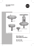
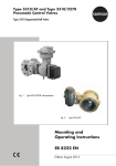
1
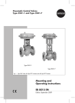
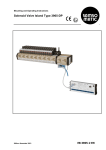
Pneumatic Control Valves
Type 3248-1 and Type 3248-7
Fig. 1 · Type 3248 as globe valve and angle valve, both with Type 3277 Pneumatic Actuator
Mounting and
Operating Instructions
EB 8093 EN
Edition December 2010
Contents
Contents
Page
1
Design and principle of operation. . . . . . . . . . . . . . . . . . . . 4
2
2.1
2.2
Assembling and adjusting valve and actuator . . . . . . . . . . . . . . . 6
Option to pretension the springs for actuator version
"Actuator stem extends" . . . . . . . . . . . . . . . . . . . . . . . . . 7
Valve and actuator that have different rated travels. . . . . . . . . . . . 8
3
3.1
3.2
Installation . . . . . . . . . . . . . . . . . . . . . . . . . . . . . . . 8
Mounting position. . . . . . . . . . . . . . . . . . . . . . . . . . . . 8
Signal pressure line . . . . . . . . . . . . . . . . . . . . . . . . . . . 8
4
Operation . . . . . . . . . . . . . . . . . . . . . . . . . . . . . . . 9
5
5.1
Maintenance . . . . . . . . . . . . . . . . . . . . . . . . . . . . . . 9
Replacing packing, seat and plug . . . . . . . . . . . . . . . . . . . 10
6
Protective cover . . . . . . . . . . . . . . . . . . . . . . . . . . . . 12
7
Customer inquiries . . . . . . . . . . . . . . . . . . . . . . . . . . 14
Note:
Non-electrical actuators and valves do not have their own potential ignition source
according to the risk assessment in the rare incident of an operating fault, corresponding to
EN 13463-1: 2001 paragraph 5.2, and therefore do not fall within the scope of the
European Directive 94/9/EC.
Refer to paragraph 6.3 of EN 60079-14:1977 (VDE 0165 Part 1) concerning connection to
the equipotential bonding system.
2
EB 8093 EN
Safety instructions
General safety instructions
4 The control valve must only be mounted, started up or serviced by fully
4
4
4
4
trained and qualified personnel, observing the accepted industry codes and
practices. Make sure employees or third persons are not exposed to any
danger. All safety instructions and warnings in these mounting and
operating instructions, particularly those concerning assembly, start-up and
maintenance, must be observed.
The control valves fulfill the requirements of the European Pressure
Equipment Directive 97/23/EC. Valves with a CE marking have a
declaration of conformity that includes information about the applied
conformity assessment procedure.
The corresponding declaration of conformity can be viewed and
downloaded on the Internet at http://www.samson.de.
For appropriate operation, make sure that the control valve is only used in
areas where the operating pressure and temperatures do not exceed the
operating values which are based on the valve sizing data submitted in the
order. The manufacturer does not assume any responsibility for damage
caused by external forces or any other external influence!
Any hazards which could be caused in the control valve by the process
medium, operating pressure, signal pressure or by moving parts are to be
prevented by means of the appropriate measures.
Proper shipping and appropriate storage of the control valve are assumed.
CAUTION!
4 For installation and maintenance work on the valve, make sure the relevant
4
4
section of the pipeline is depressurized and, depending on the process
medium, drained as well. If necessary, allow the control valve to cool down
or warm up to reach ambient temperature prior to starting any work on the
valve.
Prior to performing any work on the valve, make sure the supply air and
control signal are disconnected or blocked to prevent any hazards that could
be caused by moving parts.
Special care is needed for pneumatic control valves when the actuator
springs are pretensioned. These actuators are labeled correspondingly and
can also be identified by three long bolts protruding from the bottom of the
actuator. Prior to starting any work on the control valve, relieve the
compression from the pretensioned springs.
EB 8093 EN
3
Design and principle of operation
of
The test connection (42) allows the pressure
to be monitored in order to check the metal
bellows for leakage.
The Type 3248 Cryogenic Valve can be
combined with either a Type 3271 or a
Type 3277 Pneumatic Actuator with integral
positioner attachment.
The process medium flows through the valve
in the direction indicated by the arrow. The
position of the plug (5) is determined by
changes in the signal pressure acting on the
actuator diaphragm.
1
Design and
operation
principle
The globe-pattern or angle-pattern valve
body is designed for welding in vacuum-insulated pipelines or for installation in
cold-box applications. The cryogenic extension bonnet consists of a metal bellows located directly above the valve body and the
insulating section above the bellows seal.
The plug stem extension consists of a spacer
stem (71) and bellows stem (37). The stem
extension is connected by the stem connector (A.51) to the actuator stem (A.7).
The plug stem is sealed by the metal bellows
and the backup packing(15) with
spring-loaded PTFE-carbon V-ring packing
(Fig. 6).
14
Fig. 2 · Type 3248 as angle valve in aluminum
4
EB 8093 EN
Fig. 3 · Valve bonnet with Type 3277 Actuator
Design and principle of operation
A.1
A.9
A.7
A.51
84
2
32
33
95.9
95
95.2
Legend
1
1.2
Valve body
Cryogenic extension bonnet
2
Valve bonnet
4
5
Seat
Plug
8
Threaded bushing
9
10
8
15
17
9
10
Stem connector nut
Lock nut
15
Packing
17
24
Gasket
Guide bushing
42
43
30
Washers
71
32
33
Studs
Nuts for studs
35 Nut for guide bushing
37 Bellows stem with metal bellows
37.2 Seal (for metal sealing)
37
41
37.2
30
1.2
35
24
5
4
1
41
42
43
71
84
95
95.2
95.9
Bellows nut
Test connection
Flat gasket
Spacer stem
Travel scale indicator
Protective cover
Adjustment bolt for protective cover
Spacer sleeve/washer
A.1
A.7
A.9
A.51
Actuator
Actuator stem
Annular ring
Stem connector
Fig. 4 · Type 3248-1: Type 3248 Globe Valve with Type 3271 Pneumatic Actuator
EB 8093 EN
5
Assembling and adjusting valve and actuator
Fail-safe position:
Depending on how the springs are arranged
in the actuator, the control valve assumes
one of two different fail-safe positions:
Actuator stem extends:
When the pressure is relieved or the supply
air fails, the actuator springs move the actuator stem downwards and close the valve.
Actuator stem retracts:
When the pressure is relieved or the supply
air fails, the actuator springs move the actuator stem upwards and open the valve.
2
Assembling and
valve and actuator
adjusting
If the valve and actuator have not been preassembled by the manufacturer or in the
case that the original actuator attached to
the valve is to be replaced by another actuator of a different type or size, proceed as
follows:
Removing a mounted actuator
Note:
For actuators with fail-safe action "Actuator
stem extends" and especially actuators with
pretensioned springs, apply a pressure
slightly higher than the lower bench range
(see actuator nameplate) to the loading
pressure connection on the bottom
diaphragm chamber before undoing the
annular nut (A.9).
4 Remove clamps of the stem connector
4
(A.51) between the actuator stem and
spacer stem and unscrew annular nut
(A.9).
Lift the actuator (A.1) off the valve.
Mounting the actuator
1. Loosen the lock nut (10) and stem connector nut (9) on the valve. Firmly press
the plug (5) with the plug stem into the
seat (4). Then thread down the lock nut
and stem connector nut.
2. Remove clamps of the stem connector
(A.51) and annular nut (A.9) on the actuator (A.1).
Fig. 5 · Valve bonnet with yoke (PN 100/Class 600)
6
EB 8093 EN
Assembling and adjusting valve and actuator
3. Slide the annular nut over the spacer
stem (71).
4. Place the actuator on the valve bonnet
(2) and screw tight using the annular nut
(A.9).
5. Read the nameplate on the actuator to
determine which bench range (signal
range with pretensioned springs) and
which fail-safe are used.
The fail-safe action "Actuator stem extends"
or "Actuator stem retracts" is indicated on
the nameplate by FA or FE respectively on
the Type 3271 Actuator and by the appropriate symbol on the Type 3277 Actuator.
The lower bench range corresponds to the
lower signal pressure range to be adjusted,
while the upper bench range corresponds to
the upper signal pressure range.
6. For actuators with fail-safe action "Actuator stem extends", apply the pressure
corresponding to the lower signal pressure range (e.g. 0.2 bar) to the loading
pressure connection on the bottom diaphragm chamber.
For actuators with fail-safe action "Actuator stem retracts", apply the pressure
corresponding to the upper signal pressure range (e.g. 1 bar) to the loading
pressure connection on the top diaphragm chamber.
7. Thread on the stem connector nut (9) by
hand until it touches the actuator stem
(A.7) and then turn it a further ¼ turn.
Secure this position with the lock nut
(10).
8. Position clamps of the stem connector
(A.51) and fasten tight.
9. Align travel indicator scale (84) with tip
of the stem connector; for actuators with
"Actuator stem extends" align it with
lower marking (valve closed) and for actuators with "Actuator stem retracts"
align it with top marking (valve open).
2.1
Option to pretension the
springs for actuator version
"Actuator stem extends"
To achieve a greater thrust, the actuator
springs can be pretensioned by 12.5 %
(240 cm²), by 25 % (350 and 700 cm²) or
by 75 % (700 cm²) of their travel or their
bench range.
If, with a bench range of 0.2 to 1 bar, the
springs are to be pretensioned by 0.1 bar,
for example, the bench range is shifted by
0.1 bar to 0.3 bar.
When adjusting the valve, a signal pressure
of 0.3 bar is to be set as the lower signal
pressure range.
The new bench range of 0.3 to 1.1 bar must
be marked on the nameplate as the bench
range with pretensioned springs.
EB 8093 EN
7
Installation
2.2
Valve and actuator that have
different rated travels
Actuators with springs that have already
been pretensioned by the manufacturer
without attachment to a valve are marked by
an appropriate label.
In addition, such actuators can be identified
by three bolts protruding from the bottom diaphragm case which allow the spring compression to be unloaded evenly before removing the actuator from the valve.
3
Installation
3.1
Mounting position
The valve can be mounted in any position.
It must be installed free of tension.
If necessary, supports can be mounted on
the pipelines near the connections.
If an actuator with a side-mounted
handwheel is installed at an angle less than
45° to the horizontal, the actuator must be
additionally supported.
CAUTION!
Prior to welding the valve body into the
pipeline, apply air pressure for valves with
fail-safe action “Actuator stem extends”
(valve closed) to move the valve plug out of
the seat. This prevents the trim from being
damaged by excessive high temperatures.
Note:
Remove the stopper from the test connection
(42) to allow the metal bellows (37) to be
monitored for leakage.
3.2
Signal pressure line
Connect the signal pressure line for valves
with fail-safe action "Actuator stem extends"
to the loading pressure connection on the
bottom diaphragm case, and for valves with
fail-safe action "Actuator stem retracts" to
the loading pressure connection on the top
diaphragm case.
The lower connection of Type 3277 Actuator
is located on the yoke at the bottom diaphragm case.
8
EB 8093 EN
Operation
4
Operation
To reverse the direction of action, refer to
Mounting and Operating Instructions of the
respective pneumatic actuator:
EB 8310 EN for Type 3271
EB 8311 EN for Type 3277
5
Note:
Seat wrenches can be ordered using the
following order numbers:
For DN 15 to 150: Complete set 1280-3047
For DN 15 and 25: Single set 1280-3073
Maintenance
If leakage occurs, this could be caused by a
damaged metal bellows (37) or a defective
packing (15).
If the valve does not seal properly, the tight
shut-off may be impeded by dirt or other impurities caught between the seat and plug,
or by damaged facings.
Remove the parts, clean them thoroughly
and replace them with new ones, if necessary.
Before servicing or disassembling the
control valve, depressurize the relevant section of the plant and drain it.
Wait until the medium has reached
ambient temperature, if necessary.
As valves are not free of cavities,
there might still be residual medium
in the valve.
We recommend removing the valve
from the pipeline or the entire valve
assembly when the valve is welded
in the pipeline.
On performing any work on the
valve body, first shut off the supply
pressure, disconnect the supply pressure line and remove the actuator.
EB 8093 EN
9
Maintenance
5.1
Replacing packing, seat and
plug
washer (12), and spring (11).
Replace damaged parts with new ones.
Carefully clean the packing chamber.
Removing the actuator
Prior to performing any work on the valve
body, remove the actuator first.
Note:
For actuators with fail-safe action "Actuator
stem extends" and especially actuators with
pretensioned springs, apply a pressure
slightly higher than the lower bench range
(see actuator nameplate) to the loading
pressure connection on the bottom
diaphragm chamber before undoing the
annular nut (A.9).
1. Remove clamps of the stem connector
(A.51) between actuator stem and
spacer stem and unscrew annular nut
(A.9).
2. Lift the actuator off the valve.
Plug
1. Unscrew spacer stem (71).
2. Use a SAMSON socket wrench to
unscrew the bellows nut (41). Pull out the
bellows stem together with the metal bellows (37), guide bushing (24) and plug
(5) from the cryogenic extension bonnet
(1.2).
3. Use a suitable tool to clamp the bellows
stem (37) tightly.
4. Unthread the plug from the bellows
stem.
5. Loosen nut (35). Unscrew guide bushing
(24). In the case of large nominal sizes,
unscrew second nut and remove guide
bushing.
Packing (Fig. 6)
8
1. Unscrew the stem connector nut (9) and
lock nut (10).
2. Undo threaded bushing (8) to relieve the
tension from the packing (15).
3. Unthread the nuts (33) at the valve bonnet. Lift valve bonnet upwards off the
flanged section of the cryogenic extension bonnet (1.2).
4. Unthread threaded bushing (8) and use
a suitable tool to remove the packing
(15) including the packing rings (16),
2
16
10
EB 8093 EN
12
11
71
Fig. 6 · Packing
15
Maintenance
Note: There is no guide bushing in valve
sizes NPS 4 and 6/Class 150 and 300 with
reduced overall height.
6. Apply lubricant (order no. 8150-0116)
to the plug stem thread of the new or
original plug that has been machined.
7. Screw guide bushing (24) onto the bellows stem as far as it will go. Lock into
position with the nut (35) or slide on the
guide bushing and fasten with two nuts.
8. Replace old washers (30) with new ones.
Screw the plug stem tightly into the bellows stem.
Tightening torque:
50 Nm for DN 25 to 80 (NPS 1 to 3)
140 Nm for DN 100 to 150 (NPS 4 to 6).
Seat
If the seat must also be replaced, proceed as
follows:
9. Use a SAMSON seat wrench to unscrew
the seat (4) out of the valve body.
10. Apply lubricant (order no. 8150-0116)
to the seat thread of the new seat and
screw in tightly observing the tightening
torques in Table 1.
Assembly
1. Slide bellows stem together with metal
bellows (37), guide bushing (24) and
plug into the body.
2. Insert bellows nut (41) and screw tight.
Screw spacer stem onto the bellows stem
(observing tightening torques in Table
1).
3. Insert new gasket (17) into the flanged
section. Slide valve bonnet over the
spacer stem and place it on the flanged
section.
4. Thread on nut (33) and screw tight, observing the tightening torques in Table 1.
5. Apply lubricant (order no. 8150-0116)
to packing parts and threaded bushing
(8).
Slide spring (11), washer (12) and new
packing rings (16) over the spacer stem
into the packing chamber.
Put on threaded bushing (8) and tighten
it as far as it will go.
Table 1 · Tightening torques in Nm for steel and aluminum versions
Nominal size
DN
NPS
Body nuts (33/14)
Seat (4, material)
CrNiMo
Stellite
2.4610
2.4819
2.4360
Bellows
nut
(41)
Globe valve (33)
PN 40
Cl 300
PN 100
Cl 600
Aluminum
angle valve
(14)
Spacer
stem
(71)
15...25
½ ...1
160
170
130
200
40
50
30
30
32...50
1½ ...2
480
500
380
1000
80
80
40
30
65...80
2½ ...3
900
1050
800
2000
150
110
60
30
100
4
1250
1550
1150
3200
130
150
100
40
150
6
2300
2600
2000
3840
130
190
120
40
EB 8093 EN
11
Protective cover
6. Screw the lock nut (10) and nut (9)
loosely onto the spacer stem (71).
7. Mount actuator and adjust the lower or
upper bench range as described in section 2.
6
Protective cover
To keep the overall height of the valve as
small as possible for transportation purposes
in cold-box installations, the actuator and
valve bonnet must be removed from the
flanged section of the cryogenic extension
bonnet and the bellows stem protected by a
protective cover.
General
The protective cover with adjustment bolt
must meet the following requirements when
the valve is installed in the plant:
4 Opening the valve to its rated travel to
4
allow the pipeline and the valve to be
rinsed.
Closing the valve to perform a pressure
test (to check the tightness of the plant
section). The bellows seal in this case is
the primary sealing element. The protective cover merely serves to transfer the
force.
Description of the function
In the delivered state, the protective cover is
mounted and the valve is open (the thread of
the bellows stem is completely screwed into
the adjustment bolt).
To perform the leak test in the plant section,
the adjustment bolt must be threaded counterclockwise (valve closed).
linksdrehen zum Schließen/
counter clockwise to close
95.3
95.4
MA
32
33
95.9
95.1
95.7
42
95.5
43
95.6
95.2
37
F
Fig. 7 · Protective cover
12
EB 8093 EN
Schließkraft/
closing force
Legend
32 Stud
33 Nut
37 Bellows stem with
metal bellows
42 Test connection
43 Flat gasket
95.1 Protective cover
95.2 Adjustment bolt
(SW 19)
95.3 Retaining ring
95.4 O-ring
95.5 Screw plug
95.6 Flat gasket
95.7 O-ring
95.9 Spacer sleeve/
washer
Protective cover
If the adjustment bolt is turned clockwise, the
plug is lifted out of the seat (valve opens).
Mounting the protective cover
Note:
For actuators with fail-safe action "Actuator
stem extends" and especially actuators with
pretensioned springs, apply a pressure
beforehand to retract the actuator stem
slightly.
1. Remove the mounted actuator as described in section 2.
2. Detach the spacer stem (71) from the
bellows stem (37) by unscrewing the
stem connector nut and lock nut.
3. Remove the nuts (33) on the valve bonnet. Carefully lift off the valve bonnet (2)
including the spacer stem from the
flanged section of the cryogenic extension bonnet (1.2).
4. Align the protective cover with stuck-on
O-ring (95.7) onto the studs (32).
5. Place the protective cover with adjustment bolt (95.2) on the thread of the bellows stem (37).
6. Turn the adjustment bolt (SW 19) clockwise until the protective cover (95.1) is
seated on the flange.
8. Fasten tight the studs (32) with nuts (33)
and spacer sleeves/washers (95.9).
Removing the protective cover
1. Remove the nuts (33) and washers/spacer sleeves (95.9).
2. Turn the adjustment bolt (95.2) counterclockwise. The plug is lowered and the
protective cover is lifted off the flange.
3. After reaching the threaded end of the
bellows stem (37), remove the protective
cover.
4. Use the nuts (33) to mount the actuator!
The washers/spacer sleeves (95.9) are
no longer required.
Mounting the valve bonnet with spacer
stem
1. Insert a new gasket (17) into the body
flange.
2. Place the valve bonnet (2) with spacer
stem (71) onto the body flange. To do
so, place the spacer stem over the thread
of the bellows stem (37) and hand
tighten. While doing so, do not change
the position of the stem connector nut (9)
or the lock nut (10) on the spacer stem!
3. Tighten the nuts (33) on the studs (32) in
a criss-cross pattern using the torque
listed in Table 1.
4. Use the stem connector nut (9) to fasten
tight the spacer stem (71) and the bellows stem (37) using the torque listed in
Table 1.
5. Check whether the threaded bushing (8)
is tightened as far as it will go.
6. Mount the actuator.
If the position of the stem connector nut
and lock nut has not changed while the
EB 8093 EN
13
Customer inquiries
valve bonnet was removed, the bench
range is still correct and does not need
to re-adjusted.
When the stem connector nut and lock
nut have been removed, the spacer stem
can also be tightened over its hexagonal
end.
Further information
Further information, e.g. required tightening
torques, can be found in the special documentation TV-SK 9626.
7
Customer inquiries
Please submit the following details:
4 Type designation and order number (on
nameplate)
4 Serial number, nominal size and version
of the valve
4 Pressure and temperature of the process
medium
4 Flow rate in m³/h
4 Bench range (spring range) (e.g. 0.2 to
1 bar) of the actuator
4 Installation drawing
Dimensions
Refer to the Data Sheet T 8093 EN for the
dimensions and weights of the various valve
versions.
14
EB 8093 EN
EB 8093 EN
15
EB 8093 EN
S/Z 2011-01
SAMSON AG · MESS- UND REGELTECHNIK
Weismüllerstraße 3 · 60314 Frankfurt am Main · Germany
Phone: +49 69 4009-0 · Fax: +49 69 4009-1507
Internet: http://www.samson.de