1
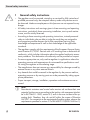
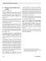
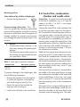
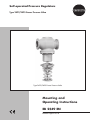
Self-operated Pressure Regulators Type 2422/2425 Excess Pressure Valve Type 2422/2425 Excess Pressure Valve Mounting and Operating Instructions EB 2549 EN Edition April 2014 Definition of signal words DANGER! Hazardous situations which, if not avoided, will result in death or serious injury WARNING! Hazardous situations which, if not avoided, could result in death or serious injury 2 NOTICE Property damage message or malfunction Note: Additional information Tip: Recommended action EB 2549 EN Contents ContentsPage 1 General safety instructions..............................................................................4 2 Process medium and scope of application........................................................5 2.1 Transportation and storage..............................................................................5 3 Design and principle of operation...................................................................6 4 Installation.....................................................................................................8 4.1 Assembly.......................................................................................................8 4.2 Mounting position...........................................................................................9 4.3 Notes on installation.......................................................................................9 4.4 Control line, condensation chamber and needle valve......................................10 4.5 Strainer........................................................................................................11 4.6 Shut-off valve................................................................................................11 4.7 Pressure gauge.............................................................................................11 5 Operation....................................................................................................12 5.1 Start-up........................................................................................................12 5.2 Adjusting the set point...................................................................................12 5.3 Decommissioning..........................................................................................13 6 Maintenance and troubleshooting.................................................................13 6.1 Replacing the operating diaphragm...............................................................13 7 Nameplate...................................................................................................14 8 Customer service..........................................................................................15 9 Dimensions..................................................................................................16 10 Technical data..............................................................................................18 EB 2549 EN 3 General safety instructions 1 General safety instructions −− The regulator must be mounted, started up or serviced by fully trained and qualified personnel only; the accepted industry codes and practices are to be observed. Make sure employees or third persons are not exposed to any danger. −− All safety instructions and warnings given in these mounting and operating instructions, particularly those concerning installation, start-up and maintenance, must be strictly observed. −− According to these mounting and operating instructions, trained personnel refers to individuals who are able to judge the work they are assigned to and recognize possible dangers due to their specialized training, their knowledge and experience as well as their knowledge of the applicable standards. −− The regulators comply with the requirements of the European Pressure Equipment Directive 97/23/EC. Devices with a CE marking have a declaration of conformity, which includes information about the applied conformity assessment procedure. This declaration of conformity can be provided on request. −− To ensure appropriate use, only use the regulator in applications where the operating pressure and temperatures do not exceed the specifications used for sizing the regulator at the ordering stage. −− The manufacturer does not assume any responsibility for damage caused by external forces or any other external factors. −− Any hazards that could be caused in the regulator by the process medium, operating pressure or by moving parts are to be prevented by taking appropriate precautions. −− Proper transport, storage, installation, operation and maintenance are assumed. 4 Note: Non-electric actuators and control valve versions do not have their own potential ignition source according to the ignition risk assessment stipulated in EN 13463-1: 2009, section 5.2, even in the rare incident of an operating fault. Therefore, they do not fall within the scope of Directive 94/9/EC. For connection to the equipotential bonding system, observe the requirements specified in section 6.3 of EN 60079-14 (VDE 0165 Part 1). EB 2549 EN Process medium and scope of application 2 Process medium and scope of application Pressure regulator for liquids, gases and vapors up to 350 °C For controlling the upstream pressure p1 to the adjusted set point. The valve opens when the upstream pressure rises. The upstream pressure is transmitted to the actuator over a control line that must be installed on site. The pressure regulators are not shut-off devices guaranteeing tight shut-off. When closed, these regulators can have a leakage rate of ≤ 0.05 % of the KVS coefficient. Overpressure protection must be installed in the plant. WARNING! Risk of injury and property damage due to high pressure in the plant. A suitable overpressure protection must be installed on site in the plant section. 2.1 Transportation and storage The regulator must be carefully handled, transported and stored. Protect the excess pressure valve against adverse influences, such as dirt, moisture or frost, during storage and transportation. When regulators are too heavy to be lifted by hand, fasten the lifting sling at a suitable place on the valve body. WARNING! Incorrectly attached lifting slings or supports. Risk of injury and property damage due to valve falling. Securely fasten slings or supports to the valve body and secure against slipping. EB 2549 EN 5 Design and principle of operation 3 Design and principle of operation See Fig. 1 and Fig. 2. The Type 2422/2425 Excess Pressure Valve consists of the Type 2422 Valve and the Type 2425 Actuator. The Type 2422 Valve is available either balanced by a bellows or a diaphragm. The excess pressure valve is used to maintain the pressure upstream of the valve to an adjusted set point. The valve opens when the upstream pressure rises. The medium flows through the valve in the direction indicated by the arrow. The position of the plug (3) determines the flow rate across the area released between plug and valve seat (2). The plug stem (4) with the plug is connected to the top diaphragm stem (8) of the actuator (10). The upstream pressure p1 is regulated by the positioning springs (11) and the set point adjuster (13). When relieved of pressure, the valve is closed by the force of the set point springs. The upstream pressure p1 to be controlled is tapped upstream of the valve and transmitted over the control line to the operating diaphragm (9) where it is converted into a positioning force. This force is used to move the valve plug according to the force of the positioning springs. When the force resulting from the upstream pressure p1 rises above the adjusted set point, the valve opens proportionally to the change in pressure. The principle of operation of the Type 2422/2425 Excess Pressure Valve bal6 anced by a bellows or diaphragm only differs concerning the pressure balancing. The valves balanced by a diaphragm have a balancing diaphragm (5.1) instead of a bellows (5). In both cases, the forces created by the upstream and downstream pressures that act on the valve plug are balanced out. The valves can be supplied with flow divider St I or St III. The valve seat must be replaced on retrofitting the flow divider. The control of vapors and liquids above 150 °C is only possible with a Type 2422 Valve balanced by a bellows. In this case, condensation chamber (20) is already installed in the control line 1). The needle valve (18) in the control line is open and leadsealed. Before start-up, fill the condensation chamber with the process medium at the filling opening (21) until it overflows. _ 1) Only in combination with a control line kit. Otherwise, the condensation chamber must be ordered separately (see u T 2595). EB 2549 EN Design and principle of operation 20 21 1 Type 2422 Valve, balanced by a bellows p1 p2 2 3 6.1 4 5 19 6 7 6.2 8 18 Type 2425 Actuator 8.1 15 9 14 17 16 11 13 1 2 3 4 4.1 5 6 6.1 Type 2422 Valve Seat (exchangeable) Plug Plug stem Actuator stem Balancing bellows Bellows housing Vent screw (640 cm², bellows housing) 6.2 Vent screw (connection to actuator) 7 8 8.1 9 10 11 13 14 15 16 17 Coupling nut Top diaphragm stem Nut Operating diaphragm Type 2424 Actuator Positioning springs Set point adjuster Bottom diaphragm stem Nuts and bolts Nut Diaphragm plate 18 21 Control line connection (for steam including screw joint with restriction and needle valve) Control line Condensation chamber for temperatures above 150 °C and for steam Filling opening with plug p1 Upstream pressure p2 Downstream pressure 19 20 Fig. 1: Functional diagram of Type 2422/2425 balanced by a bellows EB 2549 EN 7 Installation Type 2422 Valve, balanced by a diaphragm P1 P2 5.1 Type 2425 Actuator 5.1 Balancing diaphragm p1 Upstream pressure p2 Downstream pressure Fig. 2: Functional diagram of Type 2422/2425 balanced by a diaphragm 4 Installation See Fig. 1 and Fig. 2. 4.1 Assembly Valve and actuator can be assembled before or after the valve has been installed in the pipeline. ÎÎ Place the actuator on the bellows housing and carefully screw it in as far as it will go. Make sure the control line connection points toward the upstream pressure side. ÎÎ Hold the actuator and fasten it to the bellows housing using the coupling nut (7). ÎÎ Relieve the positioning springs of tension by turning the set point adjuster (13). 8 EB 2549 EN Installation 4.2 Mounting position −− Direction of flow must match the direction indicated by the arrow on the body. Select the installation location making sure that the regulator is installed at a distance of at least six times the nominal size (DN) away from pipe fittings or instruments that cause flow turbulence (e.g. pipe bends, manifolds, pressure measuring points or other valves). They can change the flow conditions which may lead to an instable control process especially in applications with gases, air or steam. −− Install the regulator free of stress. If necessary, support the pipeline near to the connecting flanges. Do not attach supports directly to the valve or actuator. −− Install a strainer upstream of the regulator. −− Protect the regulator from icing up when controlling media that can freeze. If necessary, depressurize and drain the regulator and remove it from the pipeline while the plant is shut down. Contact SAMSON to obtain the TV-SK 17041 documentation which contains more details on installation requirements. 4.3 Notes on installation Install the excess pressure valve in horizontal pipelines. −− Flush the pipeline thoroughly before installing the regulator to ensure that no impurities impair the proper functioning of the valve, above all the tight shut-off. 1 1 3 p1 Fig. 3: Sample application EB 2549 EN 2 6 4 5 1 p2 1 Shut-off valve 2 Upstream pressure gauge 3 Strainer (filter) 4 Type 2422/2425 Excess Pressure Valve 5 Downstream pressure gauge 6 Bypass piping p1 Upstream pressure p2 Downstream pressure 9 Installation Mounting position Valve balanced by a bellows/diaphragm −− Actuator facing downward Pressure testing of the plant · The pressure must not exceed the maximum permissible pressure of the regulator and plant on testing the pressure of the plant when the regulator is already installed. An excessive test pressure can damage the operating diaphragm in the actuator. NOTICE Uncontrolled excess pressure in the plant may damage the operating diaphragm. The maximum permissible pressure at the actuator must not exceed the pressure specified in Table 1. Table 1: Max. perm. pressure at actuator Actuator area Max. perm. pressure 640 cm² 1.5 bar 320 cm² 3 bar To prevent damage to the diaphragm, take one of following precautions: −− Remove the regulator from the pipeline or isolate the regulator in the pipeline and install a bypass (see Fig. 3) or −− Detach the control line and seal the openings with end plugs or −− Install a shut-off valve in the control line. 10 4.4 Control line, condensation chamber and needle valve Control line · A control line must be provided at the site of installation, e.g. a 3/8“ pipe for steam or an Ø8 x 1 or Ø6 x 1 mm copper pipe for air or water. Connect the control line to the upstream line (p1) at least one meter away from the valve inlet. If a manifold is located upstream of the excess pressure valve, connect the valve to the manifold, even if it is several meters away. If the upstream line is extended by a conical expansion piece, connect the control line in the expanded section of the line. Weld the control line at the side in the middle of the pipe, inclining at a ratio of approximately 1:10 up to the condensation chamber. Weld the line coming from the pressure tapping point to the 3/8“ pipe socket on the chamber. Install the condensation chamber at the highest point of the pipeline. Consequently, the control line between condensation chamber and actuator must also be installed with a downward slope. In this case, use a 3/8“ pipe with screw fittings. If the control line connection is located below the middle of the valve outlet flange, arrange the condensation chamber at the same level as the outlet flange. In this case, use a pipe which is at least ½“ in size for the control line from the tapping point to the condensation chamber. If the control line is connected above the middle of the valve outlet flange, install the condensation chamber at the same level as the upstream pressure tapping point. The addi- EB 2549 EN Installation tional pressure of the condensate head must be compensated for by adjusting the set point to a higher value. Control line kit · A control line kit for tapping pressure directly at the valve body is available as an accessories part from SAMSON (for set points ≥ 0.8 bar). See u T 2595. Condensation chamber · A condensation chamber is required for liquids above 150 °C as well as for steam. The mounting position of the condensation chamber is indicated by an adhesive label on the chamber itself as well as by an arrow and the word "top" stamped on the top of the chamber. This mounting position must be adhered to; otherwise the safe functioning of the excess pressure valve cannot be guaranteed. 4.6 Shut-off valve Install a hand-operated shut-off valve both upstream of the strainer and downstream of the regulator. This allows the plant to be shut down for cleaning and maintenance, and when the plant is not used for longer periods of time (see Fig. 3). 4.7 Pressure gauge Install a pressure gauge both upstream and downstream of the regulator to monitor the pressures prevailing in the plant (see Fig. 3). Install the pressure gauge on the upstream side in front of the pressure tapping point. Needle valve · If the regulator tends to hunt, install a needle valve at the control line connection (18) in addition to the standard SAMSON screw joint with restriction. 4.5 Strainer Install the strainer upstream of the excess pressure valve (see Fig. 3). −− The direction of flow must correspond to the arrow on the body. −− The filter element must be installed to hang downwards or sideways for applications with steam. Tip: Remember to leave enough space to remove the filter element. EB 2549 EN 11 Operation 5 Operation See Fig. 1 and Fig. 2. 5.1 Start-up First start up the regulator after mounting all parts. Make sure the control line is open and correctly connected. Fill the plant slowly with the process medium. Avoid pressure surges. Open the shut-off valves first on the upstream pressure side. Afterwards, open all the valves on the consumer side (downstream of the regulator). Regulation of steam Observe the following points for applications with steam: −− Before start-up, all pipes conveying the process medium must be completely drained and dry (to prevent steam hammering). −− Before start-up, fill the condensation chamber with water at the filling opening (21) until it overflows. Screw the plug back in. −− Slowly start up the plant and allow time for the pipes and valves to warm up. Air and condensate must be allowed to escape from the plant. Install steam trap (e.g. SAMSON Type 13 E) or air vent for steam-operated systems (e.g. SAMSON Type 3) at a suitable location. Regulation of liquids For temperatures above 150 °C, first fill the condensation chamber with the process medium. 5.2 Adjusting the set point Adjust the required upstream pressure by turning the set point adjuster (13). Turn clockwise −− The upstream pressure is increased (higher pressure set point) Turn counterclockwise −− The upstream pressure is reduced (lower pressure set point) When the force resulting from the upstream pressure p1 rises above the adjusted set point, the valve opens proportionally to the change in pressure. Tip: Monitor the adjusted set point pressure at the pressure gauge on the upstream pressure side. Changing the set point range The set point range is determined by the size of the actuator and its positioning springs. The set point range can only be changed by exchanging the entire actuator assembly. Therefore, we recommend contacting us if you want to change the set point range. To start up the excess pressure valve, open shut-off valves slowly. Undo the vent screw (6.1) in 640 cm² actuators until all the air has escaped. Tighten the screw again. 12 EB 2549 EN Maintenance and troubleshooting 5.3 Decommissioning Close first the shut-off valve on the upstream side of the valve and then on the downstream side of the valve. 6 Maintenance and troubleshooting If the upstream pressure deviates considerably from the set point, check the control line for blockage and check the diaphragm for leakage. In case of other causes, such as a damaged seat or plug, we recommend contacting SAMSON's After-sales Service Department (see section 8). If the diaphragm is damaged, proceed as described in section 6.1. WARNING! Risk of scalding due to hot process medium escaping uncontrolled. Allow the regulator to cool down before depressurizing and draining it and remove it from the pipeline. 6.1 Replacing the operating diaphragm See Fig. 1 and Fig. 2. Shut down the plant by slowly closing the shut-off valves. Depressurize the relevant section of the pipeline and, if necessary, drain it as well. EB 2549 EN The actuator can be removed from the valve without having to remove the valve from the pipeline. However, in this case, do not forget that the actuator cone seals off the bellows housing. Consequently, the process medium will drain out of the valve on removing the actuator. 1. Relieve the spring assembly of tension by turning the set point adjuster (13) counterclockwise. 2. Unscrew the control line and clean it. 3. Undo the coupling nut (7) and remove the actuator. 4. Unscrew the set point adjuster (13). Remove bearing, bushing, spring(s) and spring plate. 5. Remove nuts and bolts (15). Lift the top cover plate off the actuator stem. 6. Pull the diaphragm stems together with the diaphragm plates and the diaphragm out of the lower diaphragm case. 7. Hold the bottom nut (16) stationary using a socket wrench and unscrew the top diaphragm stem by loosening the nut (8.1) (the nut is sealed with paint!). 8. Take off the top diaphragm plate (17). Replace the operating diaphragm (9) with a new one. Proceed in the reverse order to reassemble the regulator. For start-up, proceed as described in section 5.1. 13 Nameplate 7 Nameplate Nameplates are attached to the valve and the actuator. Valve nameplate 3 2 4 1 SAMSON Kvs No 8 7 ∅p PN DN bar T 9 DIN version 5 ˚C Made in Germany 11 10 12 DIN version 1 Valve type 2 Model number with index 3 Configuration ID (Var.-ID) 4 Order number or date 5 KVS coefficient 7 1 3 2 SAMSON 4 No psi T ∅p 7 8 10 9 Size Cl Cv ˚F 5 Made in Germany 12 11 Nominal size 9 Nominal pressure 10 Perm. differential pressure 11 Perm. temperature 12 Body material ANSI version ANSI version 5 Valve size 7 Spring force 8 Perm. differential pressure 9 Perm. temperature (°F) 10 Body material 11 CV coefficient (KVS x 1.17) 12 3 2 SAMSON psi ANSI class (pressure rating) DIN/ANSI version Actuator nameplate bar bar Spring force/set point range 8 Var.-ID psi DN 9 1 4 No cm² bar 7 size 7 10 9 1 Effective area (DIN/ANSI) 2 Type 3 Configuration ID (Var.-ID) sq.in 2002 4 ID number psi 0062 7 Valve size (DIN/ANSI) 9 Set point range (DIN/ANSI) 10 Diaphragm material Made in Germany Fig. 4: Nameplates 14 EB 2549 EN Customer service 8 Customer service If malfunctions or defects occur, contact the SAMSON After-sales Service Department for support. The addresses of SAMSON AG, its subsidiaries, representatives and service facilities worldwide can be found on the SAMSON website, in all SAMSON product catalogs or on the back of these Mounting and Operating Instructions. Please send your inquiries to: [email protected] To assist diagnosis, specify the following details (see section 7): −− Type and nominal size of the valve −− Model number and configuration ID (Var.-ID) −− Order number or date −− Upstream and downstream pressure −− Temperature and process medium −− Min. and max. flow rate in m³/h −− Is a strainer installed? −− Installation drawing showing the exact location of the regulator and all the additionally installed components (shut-off valves, pressure gauge, etc.) EB 2549 EN 15 Dimensions 9 Dimensions L Type 2422/2425 ∙ Balanced by a bellows H2 H1 H ØD Dimensions in mm and weights in kg ∙ The values in parentheses apply to temperatures from 220 to 350 °C Nominal size DN 125 DN 150 DN 200 DN 250 Length L 400 mm 480 mm 600 mm 730 mm Height H1 460 (600) mm 590 (730) mm Height H2 145 mm 175 mm 990 (1130) mm 1120 (1260) 990 (1130) mm 1120 (1260) mm 0.05 to 0.25 Set point ranges in bar 0.1 to 0.6 0.2 to 1.0 0.5 to 1.5 1.0 to 2.5 Height H Actuator Height H 990 (1130) mm 1120 (1260) mm 1260 (1400) mm ØD = 380 mm, A = 640 cm² 940 (1080) mm Actuator Height H 1260 (1400) mm ØD = 380 mm, A = 640 cm² Actuator Height H 260 mm 1260 (1400) mm ØD = 380 mm, A = 640 cm² Actuator Height H 730 (870) mm 235 mm 1070 (1210) mm 1210 (1350) mm ØD = 285 mm, A = 320 cm² 940 (1080) mm Actuator 1070 (1210) mm 1210 (1350) mm ØD = 285 mm, A = 320 cm² Weight, approx. 1) (valve with actuator) for cast iron, PN 16 1) 0.05 to 1.0 135 kg 116 kg 286 kg 296 kg 0.5 to 1.5/1 to 2.5 125 kg 110 kg 280 kg 290 kg +10 % for cast steel, spheroidal graphite iron and stainless steel Fig. 5: Dimensions ∙ Type 2422/2424 ∙ Balanced by a bellows 16 EB 2549 EN Dimensions Type 2422/2425 ∙ Balanced by a diaphragm H2 H L Dimensions in mm and weights in kg Nominal size DN 125 DN 150 DN 200 DN 250 Length L 400 mm 480 mm 600 mm 730 mm Height H 720 mm 745 mm 960 mm 960 mm Height H2 145 mm 175 mm 260 mm 260 mm Weight (actuator with valve), approx. 0.05 to 1 bar 80 kg 94 kg 239 kg 249 kg 0.5 to 2.5 bar 75 kg 88 kg 233 kg 243 kg Fig. 6: Dimensions · Type 2422/2425 ∙ Balanced by a diaphragm EB 2549 EN 17 Technical data 10 Technical data Type 2422 Valve Nominal pressure PN 16, 25 or 40 Nominal size Max. permissible temperature DN 125 DN 150 DN 200 DN 250 Valve balanced by a bellows Metal seal: 350 °C · PTFE soft seal: 220 °C · EPDM or FPM soft seal: 150 °C · NBR soft seal: 80 °C 1) Valve balanced by a diaphragm 150 °C ≤ 0.05 % of KVS coefficient Leakage class according to IEC 60534-4 Type 2425 Actuator 0.05 to 0.25 bar · 0.1 to 0.6 bar · 0.2 to 1.0 bar 0.5 to 1.5 bar · 1.0 to 2.5 bar 2) Set point ranges Max. perm. pressure at actuator Effective diaphragm area Pressure Max. permissible temperature 1) 2) 320 cm² 640 cm² 3 bar 1.5 bar Gases 80 °C at the actuator 1) · Liquids 150 °C, with condensation chamber max. 350 °C · Steam with condensation chamber max. 350 °C For oxygen max. 60 °C Set point ranges above 2.5 bar, see u T 2552 · Type 2335 Excess Pressure Valve 18 EB 2549 EN Weismüllerstraße 3 · 60314 Frankfurt am Main, Germany Phone: +49 69 4009-0 · Fax: +49 69 4009-1507 [email protected] · www.samson.de EB 2549 EN 2015-04-09 · English SAMSON AG · MESS- UND REGELTECHNIK Conversion from chromate coating to iridescent passivation Conversion from chromate coating to iridescent passivation We at SAMSON are converting the surface treatment of passivated steel parts in our production. As a result, you may receive a device assembled from parts that have been subjected to different surface treatment methods. This means that the surfaces of some parts show different reflections. Parts can have an iridescent yellow or silver color. This has no effect on corrosion protection. For further information, go to u www.samson.de/chrome-en.html