1
HARDWARE USER'S GUIDE
DCAM FRAME CAPTURE KIT
Date
: 17 February 2005
Doc. no. : DCAM_FC_HG
Iss./Rev : 1.00
Page
: 33
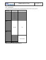
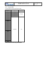
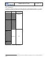
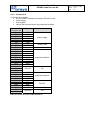
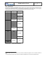
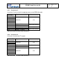
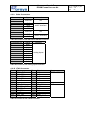
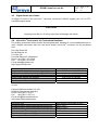
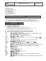
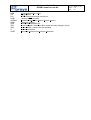
4.2.6 Connector E
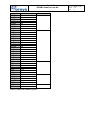
Connector E is used for the McBSP signals of port 0 and 1 and for some directly connected control
signals of the peripheral interface. It is strongly recommended to use leave these control signals
unconnected and to use the corresponding signals on the D-connector instead.
micro-line®
connector pin
E1
E2
E3
E4
E5
E6
E7
E8
E9
E10
E11
E12
E13
E14
E15
E16
E17
E18
E19
E20
E21
E22
E23
E24
E25
E26
E27
E28
E29
E30
E31
E32
Signal
(IOR/W)
(IORDY)
(/IOSTRB)
reserved
(/IORD)
(/IORW)
Interface
(peripheral
interface6)
n/a
(peripheral
interface)
reserved
n/a
DR1
DX1
CLKR1
CLKX1
FSR1
FSX1
McBSP1
reserved
n/a
DR0
DX0
CLKR0
CLKX0
FSR0
FSX0
XFOUT
(I/O4)
reserved
McBSP0
I/O pins7
n/a
Table 22: Pinout for micro-line® connector E
6
These signals should not be used on this connector. Instead, the signals on the A connector should be
used.
7
I/O 4 should not be used on this connector. Instead, the signals on the A connector should be used.