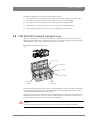
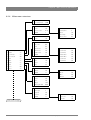
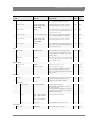
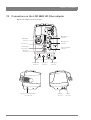
1
User’s Guide 3922 496 31001 June 2011 v4.0 LDK 8300 High-speed HD camera Declaration of Conformity We, Grass Valley Nederland B.V., Kapittelweg 10, 4827 HG Breda, The Netherlands, declare under our sole responsibility that this product is in compliance with the following standards: - EN60065 : Safety - EN55103-1: EMC (Emission) - EN55103-2: EMC (Immunity) following the provisions of: a. the Low Voltage directive 2006/95/EC b. the EMC directive 2004/108/EC FCC Class A Statement This product generates, uses, and can radiate radio frequency energy and if not installed and used in accordance with the instructions, may cause interference to radio communications. It has been tested and found to comply with the limits for a class A digital device pursuant to part 15 of the FCC rules, which are designed to provide reasonable protection against such interference when operated in a commercial environment. Operation of this product in a residential area is likely to cause interference in which case the user at his own expense will be required to take whatever measures may be required to correct the interference. Copyright Copyright Grass Valley Nederland B.V. 2011. Copying of this document and giving it to others, and the use or communication of the contents thereof, are forbidden without express authority. Offenders are liable to the payment of damages. All rights are reserved in the event of the grant of a patent or the registration of a utility model or design. Liable to technical alterations in the course of further development. Trademarks Grass Valley and Infinity are trademarks of Grass Valley, Inc. All other tradenames referenced are service marks, trademarks, or registered trademarks of their respective companies. Website Visit the Grass Valley public website to download the latest user’s guide updates and additional information about your broadcast product: www.grassvalley.com Table of contents Chapter 1 – Introduction 1.1 1.2 1.3 1.4 Welcome. . . . . . . . . . . . . . . . . . . . . . . . . . . . . . . . . . . . . . . . . . . . . . . . . . . . . . . . . . . . 13 1.1.1 About this manual . . . . . . . . . . . . . . . . . . . . . . . . . . . . . . . . . . . . . . . . . . . . . . . 13 1.1.2 Related documents . . . . . . . . . . . . . . . . . . . . . . . . . . . . . . . . . . . . . . . . . . . . . . 13 Technology. . . . . . . . . . . . . . . . . . . . . . . . . . . . . . . . . . . . . . . . . . . . . . . . . . . . . . . . . . 14 1.2.1 HD imagers . . . . . . . . . . . . . . . . . . . . . . . . . . . . . . . . . . . . . . . . . . . . . . . . . . . . 14 1.2.2 Digital processing . . . . . . . . . . . . . . . . . . . . . . . . . . . . . . . . . . . . . . . . . . . . . . . 14 1.2.3 Focus assist . . . . . . . . . . . . . . . . . . . . . . . . . . . . . . . . . . . . . . . . . . . . . . . . . . . . 14 1.2.4 Acquisition formats . . . . . . . . . . . . . . . . . . . . . . . . . . . . . . . . . . . . . . . . . . . . . . 15 1.2.5 Anylight™ anti-flicker system . . . . . . . . . . . . . . . . . . . . . . . . . . . . . . . . . . . . . . 15 1.2.6 HD Fiber transmission . . . . . . . . . . . . . . . . . . . . . . . . . . . . . . . . . . . . . . . . . . . . 15 1.2.7 LDK 4583 HD Fiber Base Station. . . . . . . . . . . . . . . . . . . . . . . . . . . . . . . . . . . . 15 1.2.8 LDK 4488 SuperXpander and LDK 4489 Xpander . . . . . . . . . . . . . . . . . . . . . . . 15 Main features . . . . . . . . . . . . . . . . . . . . . . . . . . . . . . . . . . . . . . . . . . . . . . . . . . . . . . . . 16 Accessories . . . . . . . . . . . . . . . . . . . . . . . . . . . . . . . . . . . . . . . . . . . . . . . . . . . . . . . . . 17 Chapter 2 – Installation 2.1 2.2 2.3 2.4 2.5 2.6 2.7 2.8 2.9 Mounting a lens . . . . . . . . . . . . . . . . . . . . . . . . . . . . . . . . . . . . . . . . . . . . . . . . . . . . . . 19 LDK 5302/60 2-inch viewfinder . . . . . . . . . . . . . . . . . . . . . . . . . . . . . . . . . . . . . . . . . . 20 2.2.1 Mounting viewfinder and microphone holder . . . . . . . . . . . . . . . . . . . . . . . . . . 20 2.2.2 Positioning the viewfinder . . . . . . . . . . . . . . . . . . . . . . . . . . . . . . . . . . . . . . . . . 21 2-inch viewfinder accessories. . . . . . . . . . . . . . . . . . . . . . . . . . . . . . . . . . . . . . . . . . . 22 2.3.1 LDK 5390/00 Wide angle eyepiece . . . . . . . . . . . . . . . . . . . . . . . . . . . . . . . . . . 22 2.3.2 LDK 5390/10 Left eye adapter . . . . . . . . . . . . . . . . . . . . . . . . . . . . . . . . . . . . . . 22 AJ-MC700 Microphone . . . . . . . . . . . . . . . . . . . . . . . . . . . . . . . . . . . . . . . . . . . . . . . . 23 LDK 5301/10 Tripod adapter plate . . . . . . . . . . . . . . . . . . . . . . . . . . . . . . . . . . . . . . . 24 Adjusting the shoulder pad. . . . . . . . . . . . . . . . . . . . . . . . . . . . . . . . . . . . . . . . . . . . . 25 Exchanging the camera adaptor. . . . . . . . . . . . . . . . . . . . . . . . . . . . . . . . . . . . . . . . . 26 LDK 5020/05 Universal transport case . . . . . . . . . . . . . . . . . . . . . . . . . . . . . . . . . . . . 27 Packing for return . . . . . . . . . . . . . . . . . . . . . . . . . . . . . . . . . . . . . . . . . . . . . . . . . . . . 28 Chapter 3 – Configurations 3.1 3.2 Introduction . . . . . . . . . . . . . . . . . . . . . . . . . . . . . . . . . . . . . . . . . . . . . . . . . . . . . . . . . 29 High-speed configuration . . . . . . . . . . . . . . . . . . . . . . . . . . . . . . . . . . . . . . . . . . . . . . 29 Chapter 4 – Operating instructions 4.1 4.2 Using the camera. . . . . . . . . . . . . . . . . . . . . . . . . . . . . . . . . . . . . . . . . . . . . . . . . . . . . 31 4.1.1 Switching on the power. . . . . . . . . . . . . . . . . . . . . . . . . . . . . . . . . . . . . . . . . . . 31 4.1.2 Controlling the camera. . . . . . . . . . . . . . . . . . . . . . . . . . . . . . . . . . . . . . . . . . . . 31 Location of controls . . . . . . . . . . . . . . . . . . . . . . . . . . . . . . . . . . . . . . . . . . . . . . . . . . . 32 4.2.1 Camera head controls . . . . . . . . . . . . . . . . . . . . . . . . . . . . . . . . . . . . . . . . . . . . 32 LDK 8300 High-speed HD camera User’s Guide (v4.0) 3 4.3 4.4 4.5 4.6 4.7 4.8 4.9 System Menu . . . . . . . . . . . . . . . . . . . . . . . . . . . . . . . . . . . . . . . . . . . . . . . . . . . . . . . . 33 4.3.1 Entering the System menu . . . . . . . . . . . . . . . . . . . . . . . . . . . . . . . . . . . . . . . . 34 4.3.2 Finding your way . . . . . . . . . . . . . . . . . . . . . . . . . . . . . . . . . . . . . . . . . . . . . . . . 34 4.3.3 Leaving the System Menu. . . . . . . . . . . . . . . . . . . . . . . . . . . . . . . . . . . . . . . . . 35 4.3.4 Making changes. . . . . . . . . . . . . . . . . . . . . . . . . . . . . . . . . . . . . . . . . . . . . . . . . 35 4.3.5 Undoing changes . . . . . . . . . . . . . . . . . . . . . . . . . . . . . . . . . . . . . . . . . . . . . . . . 35 Assigning user buttons . . . . . . . . . . . . . . . . . . . . . . . . . . . . . . . . . . . . . . . . . . . . . . . . 36 4.4.1 Side panel . . . . . . . . . . . . . . . . . . . . . . . . . . . . . . . . . . . . . . . . . . . . . . . . . . . . . 36 4.4.2 Front. . . . . . . . . . . . . . . . . . . . . . . . . . . . . . . . . . . . . . . . . . . . . . . . . . . . . . . . . . 36 4.4.3 Lens . . . . . . . . . . . . . . . . . . . . . . . . . . . . . . . . . . . . . . . . . . . . . . . . . . . . . . . . . . 36 4.4.4 Handgrip button . . . . . . . . . . . . . . . . . . . . . . . . . . . . . . . . . . . . . . . . . . . . . . . . . 37 Viewfinder preferences . . . . . . . . . . . . . . . . . . . . . . . . . . . . . . . . . . . . . . . . . . . . . . . . 38 4.5.1 Tally on/off switch . . . . . . . . . . . . . . . . . . . . . . . . . . . . . . . . . . . . . . . . . . . . . . . 38 4.5.2 Zebra (exposure indication) . . . . . . . . . . . . . . . . . . . . . . . . . . . . . . . . . . . . . . . . 38 4.5.3 VF Option switch . . . . . . . . . . . . . . . . . . . . . . . . . . . . . . . . . . . . . . . . . . . . . . . . 38 4.5.4 Viewfinder picture quality . . . . . . . . . . . . . . . . . . . . . . . . . . . . . . . . . . . . . . . . . 38 4.5.5 Dioptre adjustment . . . . . . . . . . . . . . . . . . . . . . . . . . . . . . . . . . . . . . . . . . . . . . 39 4.5.6 Viewfinder markers and LED indicators. . . . . . . . . . . . . . . . . . . . . . . . . . . . . . . 39 4.5.7 Focussing. . . . . . . . . . . . . . . . . . . . . . . . . . . . . . . . . . . . . . . . . . . . . . . . . . . . . . 41 Lens operation . . . . . . . . . . . . . . . . . . . . . . . . . . . . . . . . . . . . . . . . . . . . . . . . . . . . . . . 42 4.6.1 Auto iris . . . . . . . . . . . . . . . . . . . . . . . . . . . . . . . . . . . . . . . . . . . . . . . . . . . . . . . 42 4.6.2 Extended auto iris . . . . . . . . . . . . . . . . . . . . . . . . . . . . . . . . . . . . . . . . . . . . . . . 42 4.6.3 Precision focus. . . . . . . . . . . . . . . . . . . . . . . . . . . . . . . . . . . . . . . . . . . . . . . . . . 43 4.6.4 Lens indicators in the viewfinder . . . . . . . . . . . . . . . . . . . . . . . . . . . . . . . . . . . . 43 Controls on the HD Fiber adapter. . . . . . . . . . . . . . . . . . . . . . . . . . . . . . . . . . . . . . . . 44 4.7.1 Powering the camera. . . . . . . . . . . . . . . . . . . . . . . . . . . . . . . . . . . . . . . . . . . . . 44 4.7.2 Selecting monitoring signals . . . . . . . . . . . . . . . . . . . . . . . . . . . . . . . . . . . . . . . 45 4.7.3 Using audio . . . . . . . . . . . . . . . . . . . . . . . . . . . . . . . . . . . . . . . . . . . . . . . . . . . . 46 4.7.4 Intercom. . . . . . . . . . . . . . . . . . . . . . . . . . . . . . . . . . . . . . . . . . . . . . . . . . . . . . . 47 4.7.5 Communication . . . . . . . . . . . . . . . . . . . . . . . . . . . . . . . . . . . . . . . . . . . . . . . . . 48 Managing files . . . . . . . . . . . . . . . . . . . . . . . . . . . . . . . . . . . . . . . . . . . . . . . . . . . . . . . 49 4.8.1 Scene files . . . . . . . . . . . . . . . . . . . . . . . . . . . . . . . . . . . . . . . . . . . . . . . . . . . . . 49 4.8.2 Operator files . . . . . . . . . . . . . . . . . . . . . . . . . . . . . . . . . . . . . . . . . . . . . . . . . . . 49 4.8.3 Standard files . . . . . . . . . . . . . . . . . . . . . . . . . . . . . . . . . . . . . . . . . . . . . . . . . . . 49 4.8.4 Customer standard files. . . . . . . . . . . . . . . . . . . . . . . . . . . . . . . . . . . . . . . . . . . 50 Access and security . . . . . . . . . . . . . . . . . . . . . . . . . . . . . . . . . . . . . . . . . . . . . . . . . . . 51 4.9.1 User level . . . . . . . . . . . . . . . . . . . . . . . . . . . . . . . . . . . . . . . . . . . . . . . . . . . . . . 51 4.9.2 Selecting the user level . . . . . . . . . . . . . . . . . . . . . . . . . . . . . . . . . . . . . . . . . . . 51 4.9.3 Disable camera . . . . . . . . . . . . . . . . . . . . . . . . . . . . . . . . . . . . . . . . . . . . . . . . . 51 4.9.4 Camera cards . . . . . . . . . . . . . . . . . . . . . . . . . . . . . . . . . . . . . . . . . . . . . . . . . . . 51 4.9.5 Access control . . . . . . . . . . . . . . . . . . . . . . . . . . . . . . . . . . . . . . . . . . . . . . . . . . 52 4.9.6 Camera card slot . . . . . . . . . . . . . . . . . . . . . . . . . . . . . . . . . . . . . . . . . . . . . . . . 53 Chapter 5 – Video setup 5.1 5.2 5.3 5.4 4 Video acquisition modes. . . . . . . . . . . . . . . . . . . . . . . . . . . . . . . . . . . . . . . . . . . . . . . 55 Video settings. . . . . . . . . . . . . . . . . . . . . . . . . . . . . . . . . . . . . . . . . . . . . . . . . . . . . . . . 56 5.2.1 Overview . . . . . . . . . . . . . . . . . . . . . . . . . . . . . . . . . . . . . . . . . . . . . . . . . . . . . . 56 5.2.2 Standard settings . . . . . . . . . . . . . . . . . . . . . . . . . . . . . . . . . . . . . . . . . . . . . . . . 56 5.2.3 Non-standard indicator . . . . . . . . . . . . . . . . . . . . . . . . . . . . . . . . . . . . . . . . . . . . 56 Test signals. . . . . . . . . . . . . . . . . . . . . . . . . . . . . . . . . . . . . . . . . . . . . . . . . . . . . . . . . . 57 Gain. . . . . . . . . . . . . . . . . . . . . . . . . . . . . . . . . . . . . . . . . . . . . . . . . . . . . . . . . . . . . . . . 58 5.4.1 Gain selection . . . . . . . . . . . . . . . . . . . . . . . . . . . . . . . . . . . . . . . . . . . . . . . . . . 58 5.4.2 Variable gain. . . . . . . . . . . . . . . . . . . . . . . . . . . . . . . . . . . . . . . . . . . . . . . . . . . . 58 LDK 8300 High-speed HD camera User’s Guide (v4.0) 5.5 5.6 5.7 5.8 5.9 5.10 5.11 Optical filters . . . . . . . . . . . . . . . . . . . . . . . . . . . . . . . . . . . . . . . . . . . . . . . . . . . . . . . . 58 Color temperature . . . . . . . . . . . . . . . . . . . . . . . . . . . . . . . . . . . . . . . . . . . . . . . . . . . . 59 5.6.1 Selecting the color temperature . . . . . . . . . . . . . . . . . . . . . . . . . . . . . . . . . . . . 60 5.6.2 Variable color temperature. . . . . . . . . . . . . . . . . . . . . . . . . . . . . . . . . . . . . . . . . 60 5.6.3 Auto-white balance . . . . . . . . . . . . . . . . . . . . . . . . . . . . . . . . . . . . . . . . . . . . . . 61 Color correction . . . . . . . . . . . . . . . . . . . . . . . . . . . . . . . . . . . . . . . . . . . . . . . . . . . . . . 63 5.7.1 Setup using the VF menu . . . . . . . . . . . . . . . . . . . . . . . . . . . . . . . . . . . . . . . . . 63 5.7.2 Setup using the Operational Control Panel . . . . . . . . . . . . . . . . . . . . . . . . . . . . 64 Exposure time . . . . . . . . . . . . . . . . . . . . . . . . . . . . . . . . . . . . . . . . . . . . . . . . . . . . . . . 65 5.8.1 Selecting the exposure time . . . . . . . . . . . . . . . . . . . . . . . . . . . . . . . . . . . . . . . 65 5.8.2 Lighting . . . . . . . . . . . . . . . . . . . . . . . . . . . . . . . . . . . . . . . . . . . . . . . . . . . . . . . 65 5.8.3 Vertical shift (V-shift) . . . . . . . . . . . . . . . . . . . . . . . . . . . . . . . . . . . . . . . . . . . . . 66 5.8.4 Clean scan . . . . . . . . . . . . . . . . . . . . . . . . . . . . . . . . . . . . . . . . . . . . . . . . . . . . . 66 AnylightTM. . . . . . . . . . . . . . . . . . . . . . . . . . . . . . . . . . . . . . . . . . . . . . . . . . . . . . . . . . 67 Black stretch . . . . . . . . . . . . . . . . . . . . . . . . . . . . . . . . . . . . . . . . . . . . . . . . . . . . . . . . . 67 Auto skin detail . . . . . . . . . . . . . . . . . . . . . . . . . . . . . . . . . . . . . . . . . . . . . . . . . . . . . . 68 Chapter 6 – Menu structure and contents 6.1 6.2 Menu structure. . . . . . . . . . . . . . . . . . . . . . . . . . . . . . . . . . . . . . . . . . . . . . . . . . . . . . . 69 6.1.1 Top menu structure . . . . . . . . . . . . . . . . . . . . . . . . . . . . . . . . . . . . . . . . . . . . . . 69 6.1.2 Viewfinder menu structure . . . . . . . . . . . . . . . . . . . . . . . . . . . . . . . . . . . . . . . . 70 6.1.3 Lens menu structure . . . . . . . . . . . . . . . . . . . . . . . . . . . . . . . . . . . . . . . . . . . . . 71 6.1.4 Video menu structure . . . . . . . . . . . . . . . . . . . . . . . . . . . . . . . . . . . . . . . . . . . . 72 6.1.5 Video menu structure (continued) . . . . . . . . . . . . . . . . . . . . . . . . . . . . . . . . . . . 73 6.1.6 Install menu structure . . . . . . . . . . . . . . . . . . . . . . . . . . . . . . . . . . . . . . . . . . . . 74 6.1.7 Files menu structure . . . . . . . . . . . . . . . . . . . . . . . . . . . . . . . . . . . . . . . . . . . . . 75 6.1.8 Security menu structure . . . . . . . . . . . . . . . . . . . . . . . . . . . . . . . . . . . . . . . . . . 75 6.1.9 Diagnostics menu structure. . . . . . . . . . . . . . . . . . . . . . . . . . . . . . . . . . . . . . . . 76 6.1.10 Service menu structure . . . . . . . . . . . . . . . . . . . . . . . . . . . . . . . . . . . . . . . . . . . 77 Menu contents . . . . . . . . . . . . . . . . . . . . . . . . . . . . . . . . . . . . . . . . . . . . . . . . . . . . . . . 78 6.2.1 Viewfinder menu . . . . . . . . . . . . . . . . . . . . . . . . . . . . . . . . . . . . . . . . . . . . . . . . 78 6.2.2 Lens menu. . . . . . . . . . . . . . . . . . . . . . . . . . . . . . . . . . . . . . . . . . . . . . . . . . . . . 80 6.2.3 Video menu . . . . . . . . . . . . . . . . . . . . . . . . . . . . . . . . . . . . . . . . . . . . . . . . . . . . 81 6.2.4 Install menu . . . . . . . . . . . . . . . . . . . . . . . . . . . . . . . . . . . . . . . . . . . . . . . . . . . . 86 6.2.5 Files menu . . . . . . . . . . . . . . . . . . . . . . . . . . . . . . . . . . . . . . . . . . . . . . . . . . . . . 90 6.2.6 Security menu . . . . . . . . . . . . . . . . . . . . . . . . . . . . . . . . . . . . . . . . . . . . . . . . . . 91 6.2.7 Diagnostics menu . . . . . . . . . . . . . . . . . . . . . . . . . . . . . . . . . . . . . . . . . . . . . . . 92 6.2.8 Service menu . . . . . . . . . . . . . . . . . . . . . . . . . . . . . . . . . . . . . . . . . . . . . . . . . . . 94 Chapter 7 – Connectors 7.1 7.2 Camera head . . . . . . . . . . . . . . . . . . . . . . . . . . . . . . . . . . . . . . . . . . . . . . . . . . . . . . . . 97 7.1.1 Connectors on the LDK 8300 camera head . . . . . . . . . . . . . . . . . . . . . . . . . . . . 97 Connectors on the LDK 5880 HD Fiber adapter. . . . . . . . . . . . . . . . . . . . . . . . . . . . 100 Chapter 8 – Specifications 8.1 8.2 Specifications for LDK 8300 camerahead . . . . . . . . . . . . . . . . . . . . . . . . . . . . . . . . 105 8.1.1 Technical . . . . . . . . . . . . . . . . . . . . . . . . . . . . . . . . . . . . . . . . . . . . . . . . . . . . . 105 8.1.2 Dimensions . . . . . . . . . . . . . . . . . . . . . . . . . . . . . . . . . . . . . . . . . . . . . . . . . . . 107 Specifications for LDK 5880 HD Fiber adapter . . . . . . . . . . . . . . . . . . . . . . . . . . . . 108 8.2.1 Technical . . . . . . . . . . . . . . . . . . . . . . . . . . . . . . . . . . . . . . . . . . . . . . . . . . . . . 108 8.2.2 Dimensions . . . . . . . . . . . . . . . . . . . . . . . . . . . . . . . . . . . . . . . . . . . . . . . . . . . 109 LDK 8300 High-speed HD camera User’s Guide (v4.0) 5 6 LDK 8300 High-speed HD camera User’s Guide (v4.0) End-of-life product recycling Grass Valley’s innovation and excellence in product design also extends to the programs we’ve established to manage the recycling of our products. Grass Valley has developed a comprehensive end-of-life product take back program for recycle or disposal of end-of-life products. Our program meets the requirements of the European Union’s WEEE Directive and in the United States from the Environmental Protection Agency, individual state or local agencies. Grass Valley’s end-of-life product take back program assures proper disposal by use of Best Available Technology. This program accepts any Grass Valley branded equipment. Upon request, a Certificate of Recycling or a Certificate of Destruction, depending on the ultimate disposition of the product, can be sent to the requester. Grass Valley will be responsible for all costs associated with recycling and disposal, including freight, however you are responsible for the removal of the equipment from your facility and packing the equipment ready for pickup. For further information on the Grass Valley product take back system please contact Grass Valley at + 800 80 80 20 20 or +33 1 48 25 20 20 from most other countries. In the US and Canada please call 800-547-8949 or 530-478-4148. Ask to be connected to the EH&S Department. In addition, information concerning Grass Valley’s environmental policy can be found at: www.grassvalley.com/about/environmental-policy LDK 8300 High-speed HD camera User’s Guide (v4.0) 7 Important information Read these instructions carefully and retain them for future reference. Regularly check the Grass Valley website (www.grassvalley.com) for new updates of this and other user’s guides. During installation and operation of this equipment, local building safety and fire protection standards must be observed. Whenever it is likely that safe operation is impaired, the apparatus must be made inoperative and secured against any unintended operation. The appropriate servicing authority must then be informed. For example, safety is likely to be impaired if the apparatus fails to perform the intended function or shows visible damage. Any changes or modifications not expressly approved in this manual could void your authority to operate this equipment. Cautions and Warnings Read and comply with the warning and caution notices that appear in the manual. Warnings indicate danger that requires correct procedures or practices to prevent death or injury to personnel. Cautions indicate procedures or practices that should be followed to prevent damage or destruction to equipment or property. 8 LDK 8300 High-speed HD camera User’s Guide (v4.0) Warnings To prevent fire or shock hazard, do not expose the unit to rain or moisture. If the unit is in a wet or damp environment, a rain cover must be used to protect it for personal safety reasons. To avoid electrical shock, do not remove covers or panels. Refer servicing to qualified personnel only. In case of an emergency ensure that the power is disconnected. Connect the product only to a power source with the specified voltage rating. To prevent risk of overheating, ventilate the camera correctly. Do not block the hot airflow coming from the outlets on the right side of the camera head and camera adaptor. LDK 8300 High-speed HD camera User’s Guide (v4.0) 9 Precautions To ensure continual high performance from the camera take the following precautions into consideration: • Avoid damp places. If the environment is wet or damp a rain cover must be used to protect the unit. • Do not subject the unit to severe shocks or vibration. • Do not expose the camera to extremes of temperature. • Do not leave the unit in direct sunlight or close to heating appliances for extended periods. • Do not allow sunlight to shine into the viewfinder. • Do not allow laser beams to shine into the lens as this could damage the imagers. • Avoid extreme highlights as these can cause various kinds of optical reflections. • Be careful when connecting and disconnecting Fiber cables. – Do not mix units from different types of camera systems. – Do connect Grass Valley camera systems with other manufacturer’s camera system parts. • 10 Make connections swiftly and firmly to avoid false error messages. LDK 8300 High-speed HD camera User’s Guide (v4.0) Fiber-optic transmission units CLASS 1 LASER PRODUCT LASER KLASSE 1 PRODUKT Laser safety statement (Europe) Fiber-optic transmission units are classified as a "CLASS 1 Laser Product" according to EN 60825-1, Safety of Laser products. Class 1 laser products are considered safe and do not result in biological hazard if used according to the instructions. Laser safety statement (US) Fiber-optic transmission units are classified as a "CLASS 1 Laser Product" according to 21CFR 1040.10 of the US Food and Drug Administration (FDA) Center for Devices and Radiological Health. WARNING Use of controls, adjustments or performance of procedures other than those specified herein may result in hazardous radiation exposure. To ensure proper use of this product, please read this instruction manual carefully and retain for future reference. Should the unit ever require maintenance, contact an authorized service location. Fiber-optic cable precautions Fiber-optic cables and connectors are easily damaged; take the following precautions into account: – Do not bend the cable beyond the minimum permissible bend range specified for the cable. – Avoid kinks in the cable. – Avoid subjecting the cable to a high tension force (even momentarily). – Do not twist the cable when connecting it to equipment. – Insert connectors straight and fully into their corresponding sockets. – In fiber-optic cable systems always put the dust caps on cable and panel connectors immediately after disconnecting a cable. Keep the dust caps clean. LDK 8300 High-speed HD camera User’s Guide (v4.0) 11 Cleaning fiber-optic connectors WARNING Always switch off power before cleaning the connectors. WARNING Never clean an optical connector attached to a fiber that is carrying light. Particles of foreign matter on the tip of a ferrule can have a disabling effect on fiber-optic transmission. Fiber-optic connectors need to be cleaned every time they are mated and unmated; it is essential that fiber-optic users develop the necessary discipline to always clean the connectors before they are mated. Use a commerially available cleaning kit specifically designed for fiber-optic connectors and follow the manufacturer's instructions carefully. 12 • The connector sections to be cleaned include the tips and sides of ferrules, the interior walls of alignment sleeves, and the interior and exterior of connector shells. • For plugs, the interior surfaces of alignment sleeves and the tips of ferrules are to be cleaned with a cleaning stick treated with the appropriate fluid. (Cleaning sticks with a slender design are available that allow alignment sleeves to be cleaned without having to detach them.) • For jacks, it is important to clean both the tips and sides of the completely protruding ferrules. • Both the male and female connector shells tend to attract dust and metal particles, so it is important to clean both the insides and outsides. • The fiber end face and ferrule must be absolutely clean before it is inserted into a transmitter or receiver. • Mate the connector immediately! Don't let the connector lie around and collect dust before mating. • Air can be used to remove lint or loose dust from the port of a transmitter or receiver to be mated with the connector. Never insert any liquid into the ports. LDK 8300 High-speed HD camera User’s Guide (v4.0) Chapter 1 - Introduction Chapter 1 Introduction 1.1 Welcome The LDK 8300 is a high-speed, HD multi-format digital camera head using three 2/3-inch HDDPM+™ sensors. Combined with the Grass Valley LDK 5880 HD Fiber adapter and the LDK 4583 High-speed Base station, the camera head forms a flexible camera system that is equally at home in the studio or out on location. The camera system can capture and deliver HD images at single, double or triple speed frame rates. 1.1.1 About this manual The purpose of this manual is to present a detailed description of how to operate the LDK 8300 camera equipped with a dockable transmission adaptor. It provides the information necessary to use the camera in different configurations and with various attachments. With this manual it is possible to discover all the operating features of the camera and so use it to its full potential. This guide is so designed that it can be used as an introduction to those who are new to the camera, as a simple procedural guide to those who wish to set-up and start shooting immediately, and as a reference work to be consulted as required during the long life of the camera. 1.1.2 Related documents Before proceeding, check the Grass valley website at www.grassvalley.com for the latest version of this user’s guide and additional information: • Online versions of documentation; updated versions of user’s guides, data sheets, brochures, application notes in pdf-format are available for download. • Software downloads; camera software updates, release notes and installation instructions are available for download. LDK 8300 High-speed HD camera User’s Guide (v4.0) 13 Chapter 1 - Introduction 1.2 Technology 1.2.1 HD imagers The camera head uses HD-DPM+™ CCD imagers which offer superior performance and ultimate flexibility. Wide screen pictures in the high-definition formats 1080i and 720p are produced at the touch of a button. Progressive frame sampling is the native imaging mode, providing complete frame samples. The entire imager surface is used for image sampling— there are no interline transfer channels which introduce aliasing artifacts. The camera’s native multi-format capability is realized with innovative 9.2 million pixel Frame Transfer 2/3-inch CCD imagers. These allow vertically grouping of different numbers of pixels on the imagers themselves. There is no need for HDTV format conversion during digital signal processing which would lead to quality degradation. These imagers have a high dynamic range and high linear sensitivity across all camera lens apertures. Unique imager shuttering eliminates vertical smear, there is no measurable vertical smear. 1.2.2 Digital processing The advanced digital processing of the camera is based on highest performance A/D conversion with 14 bit I/O DSP and 34-bit accurate internal processing. All major camera functions are processed in the digital domain, including knee, gamma, detail, matrix and color correction. The intelligent continuous automatics function provides automatic control of black levels and black shading. Each imager provides black reference signals that are used to monitor temperature changes. This means that continuous automatic correction is applied without operator intervention. The digital detail processing uses full amplitude video RGB signals via an extended dynamic range detail circuit. Colorimetry is selected by means of a variable 6-point digital matrix or via preset matrices. Digital gamma circuits provide a wide range of standardised gamma curves and enable soft contrast in black scenes to be enhanced, together with hard contrast and saturated color in bright scenes. The matrix and gamma sequence is software programmable for precise color matching. 1.2.3 Focus assist With HDTV, focusing is even more critical than before. The LDK 8300 has special patented focusing aids. A unique viewfinder zoom function enlarges the viewfinder image instantly with a simple press-button action, thus providing improved means for focusing. Additionally, a patented crawler circuitry adds motion in the viewfinder to objects in sharp focus. 14 LDK 8300 High-speed HD camera User’s Guide (v4.0) Chapter 1 - Introduction 1.2.4 Acquisition formats The LDK 8300 acquires signals in 1080i and 720p HD formats at single, double and triple speed which are output from the high speed base station as normal or three-phase signals . At the same time, the camera provides high-quality SDTV outputs in either 50 Hz or 59.94 Hz. The following acquisition formats are available: – 1080i at 59.94 Hz and 50 Hz, 119.88 Hz and 100 Hz, 179.82 Hz and 150 Hz – 720p at 59.94 Hz and 50 Hz, 119.88 Hz and 100 Hz, 179.82 Hz and 150 Hz 1.2.5 Anylight™ anti-flicker system The LDK 8300 incorporates Grass Valley’s Anylight™ high-quality anti-flicker system which eliminates any perceived changes in light levels due to the uneven ratio between the camera scanning frequency and the alternating amplitude of artificial lights powered by mains frequency. The system ensures constant video output levels at triple speed frame rates even under difficult artificial lighting conditions. 1.2.6 HD Fiber transmission The LDK 5880 HD Fiber adapter allows video transmission and remote control of cameras up to a distance of 4,000 m (13,000 ft) and beyond, using industry standard fiber-optic cable. The communication facilities provide for two-wire or four-wire high quality intercom signals. Full camera control is provided via the Grass Valley C2IP Ethernet-based control network. 1.2.7 LDK 4583 HD Fiber Base Station The HD Fiber Base Station, as well as providing high definition outputs, optionally offers simultaneous high-end SDTV outputs. This facilitates a gradual and managed transition from SDTV to HDTV. Together with LDK 4583 High-speed Base Station, the LDK 8300 provides a digital high speed output to the studio environment. This 3x HD-SDI connection can be supplied to an external disk recorder or recording system to obtain exceptional slow motion playback performance. 1.2.8 LDK 4488 SuperXpander and LDK 4489 Xpander The optional available SuperXpander together with the LDK 4021 7-inch CRT B/W viewfinder or the LDK 4025 8-inch LCD color viewfinder turns the portable camera into a full-featured studio camera for studio and EFP situations. LDK 8300 High-speed HD camera User’s Guide (v4.0) 15 Chapter 1 - Introduction 1.3 16 Main features • Ultimate flexibility with HD-DPM+ ™ CCD imagers, offering native switchability between the interlaced 1080i and true progressive 720p high definition digital formats. • The CCDs have 9.2 million pixels each, with 1920 (H) x 4320 (V) effective picture elements. • Frame Transfer technology ensures no smear. • Highest performance A/D conversion with 14 bit I/O DSP and more than 34-bit internal digital processing with unique software programmable video path. • Anylight™ high-quality anti-flicker system ensures constant video output levels at triplespeed frame rates. • Superior all digital highlight handling with a wide dynamic range. • Unique circuitry for pivoting knee and True Color Knee. • Variable gain control and variable color temperature. • Secondary color corrector with six sets for color hue, saturation and luminance adjustment. • Wide range of presets and variable 6-point digital matrix assure accurate color matching. • Fluorescent light matrix. • Digital gamma with unique standard preset values and highest accuracy. • Digital detail with an extensive range of parameters. • Advanced detail correction includes two automatic skin settings. • Intelligent Continuous Automatics black levels, black shading and video levels - no set-up time required. • Digital contrast with standard black stretch and black press. • International standard 2/3-inch broadcast lens interface. • Optical servo-controlled four-position neutral density filter wheel. • Optical servo-controlled effect filter wheel with soft focus, four-point star and six-point star filters. • Electronic color filter can be used for creating a special look (warm/cold) of a scene, or for a smooth color temperature control around the white balance setting. • Smart card for personal settings and security. • Owner card for setting user levels, and for copying and storing control settings. • Protected, easy-to-operate controls and switches with read-out of all settings. • Viewfinder status read-out of primary camera functions. • Clean scan and V-shift features allow capture of monitor and projection screen pictures. LDK 8300 High-speed HD camera User’s Guide (v4.0) Chapter 1 - Introduction 1.4 Accessories LDK 4489 Xpander LDK 4488 SuperXpander LDK 6517 7-inch viewfinder support LDK 5302/60 2-inch viewfinder HDTV LDK 5305 5-inch viewfinder HDTV LDK 5308 8.4-inch EFP viewfinder LDK 4021 7-inch viewfinder HDTV for use with SuperXpander LDK 4025 8-inch LCD viewfinder for use with SuperXpander LDK 5390/00 Wide angle adapter for LDK 5302/60 2-inch viewfinder LDK 5390/10 Left eye adapter for LDK 5302/60 2-inch viewfinder LDK 6992/02 Sunhood for LDK 5305 5-inch viewfinder LDK 5021/05 Raincover for camera with LDK 5305 5-inch viewfinder LDK 5031/10 Tripod plate LDK 8111/37 Headset dynamic XLR-5 (double muff) LDK 8111/51 Headset dynamic XLR-5 (single muff) LDK 6985/21 Scriptboard with light LDK 5020/05 Universal transport case LDK 5020/01 Carrying bag LDK 5901/00 AC power supply 100 W LDK 8300 High-speed HD camera User’s Guide (v4.0) 17 Chapter 1 - Introduction 18 LDK 8300 High-speed HD camera User’s Guide (v4.0) Chapter 2 - Installation Chapter 2 Installation 2.1 Mounting a lens To attach a lens to the camera head proceed as follows: 1. Ensure that the lens locking ring (1) is in the unlocked position - turned counterclockwise. 2. Remove the dust protection cap (2). 3. Slot the lens into the lens mount (3). 4. Turn the lens locking ring (1) clockwise to lock the lens in place. 5. Connect the lens cable to the lens connector (4) at the right side of the camera. 6. Place the lens cable into the bottom clip at the front of the camera and clip (5) located at the side. Figure 2-1. Lens mounting 1 2 4 5 LDK 8300 High-speed HD camera User’s Guide (v4.0) 3 19 Chapter 2 - Installation Caution Do not attach a lens weighing more than 5 kg (11 lbs) to the camera without a proper lens support. When a new lens is fitted to the camera it may be necessary to carry out some adjustments to optimize its use, for example, back focus or shading. For more information about these adjustments refer to the lens manufacturer’s documentation. ☞ 2.2 Note Always mount the dust protection cap when the lens is not connected to the camera. LDK 5302/60 2-inch viewfinder 2.2.1 Mounting viewfinder and microphone holder To mount the viewfinder proceed as follows: ☞ 1. Loosen locking ring (1) of viewfinder support bracket (2) at the front of the camera handle. (As seen from the rear of the camera, turning the locking ring counterclockwise moves it towards the handle.) 2. Slide the viewfinder onto the viewfinder support bracket. 3. Tighten the locking ring (1) by turning it clockwise (as seen from rear) so that the viewfinder is mounted securely to the support. 4. Connect the viewfinder cable to the viewfinder connector socket (6) at the top right of the camera. 5. Slide the microphone holder (4) onto the viewfinder and secure with the knurled screw (5). Note Always fit the microphone holder as it functions as a safety stop for the viewfinder. 6. 20 To improve the comfort of the skin contact when using the viewfinder, fit the eye piece cover (3) to the rubber eyepiece. Spare eye piece covers (ordering number 3922 405 00461) are available via your Grass Valley representative. LDK 8300 High-speed HD camera User’s Guide (v4.0) Chapter 2 - Installation Figure 2-2. Viewfinder mounting 3 1 2 6 5 4 2.2.2 Positioning the viewfinder The horizontal position of the viewfinder can be adjusted as follows to suit your requirements: 1. Loosen the locking ring (1). (As seen from the rear of the camera, turning the locking ring counterclockwise moves it towards the handle.) 2. Slide the viewfinder horizontally along the rail to the desired position. 3. Tighten the locking ring (1) by turning clockwise. The dioptre hood and eyepiece of the viewfinder can be rotated vertically. The viewfinder can be positioned backwards and forwards along the camera axis. Loosen the support bracket round bar retaining lever (2) and slide the round bar (3) forwards or backwards. When the desired position is reached tighten the support bracket round bar retaining lever (2) again. To use the viewfinder at a distance press the button (4) below or above the eyepiece tube and swing it free of the associated clip (5). The display can now be seen from further away. Figure 2-3. Viewfinder positioning 2 1 4 5 3 LDK 8300 High-speed HD camera User’s Guide (v4.0) 21 Chapter 2 - Installation 2.3 2-inch viewfinder accessories 2.3.1 LDK 5390/00 Wide angle eyepiece If you regularly use the viewfinder at a distance, for example, when you use the camera in the hand-held position, it is recommended that you fit the optionally available wide angle eyepiece. To fit the wide angle eyepiece proceed as follows: 1. Hold the eyepiece (1) securely. 2. Press the button (2) below the eyepiece tube and swing it free of the button clip (3). 3. Press the button (4) above the eyepiece tube and remove the eyepiece. 4. Fit the wide angle eyepiece (1) to the two clips (3) ensuring that they both click into place. Figure 2-4. Viewfinder wide angle eyepiece 1 4 3 2 2.3.2 LDK 5390/10 Left eye adapter A left eye adapter is optionally available to allow the viewfinder to be used with the left eye. Before mounting the viewfinder onto the camera, attach the left eye adapter (1) to the viewfinder and secure it using the screw (2). Do not forget to mount the microphone support bracket (3) at the end of the left eye adapter. Figure 2-5. Viewfinder left eye adapter 1 22 2 3 LDK 8300 High-speed HD camera User’s Guide (v4.0) Chapter 2 - Installation 2.4 AJ-MC700 Microphone To attach the optional microphone to the camera proceed as follows: 1. Open the microphone holder by unscrewing the knurled screw (2) of the microphone support bracket (1) on the viewfinder and open. 2. Slide the microphone into the split tube until the microphone shoulder reaches the mark (5) in the tube. 3. Place the tube with the microphone into the holder with the split facing upwards. Mount the microphone as straight as possible. 4. Ensure that the rubber supports at the back and front of the holder fit into the rims (6) around the tube. 5. Close the holder and tighten the knurled screw at the top. Don’t allow the wind hood to touch the holder (7) as this reduces the damping effect. 6. Connect the microphone cable to the MIC audio connector (3) on the right side of the camera. To avoid mechanical pick-up, do not let the microphone cable touch the holder. 7. Place the microphone cable into the top clip at the front of the camera and into clip (4) at the side of the camera. (Pull and twist clip to open it.) Other microphones with a diameter of 21 mm can also be used, however, ensure that the sensitivity of the input that match that type of microphone are correctly selected in the camera INSTALL menu. When a longer microphone is used, it is not necessary to place it in the split tube. Phantom power is always present on the front microphone socket. Figure 2-6. Microphone mounting 1 5 2 6 3 4 7 LDK 8300 High-speed HD camera User’s Guide (v4.0) 23 Chapter 2 - Installation 2.5 LDK 5301/10 Tripod adapter plate To mount the camera on a tripod, the tripod plate must first be attached to the tripod. Follow the tripod manufacturer’s instructions to mount the wedge plate supplied with the tripod and the tripod adapter plate firmly onto the tripod. Attach the camera to the tripod adapter plate as follows: 1. Slide the camera horizontally along the tripod adapter plate from back to front ensuring that the front of the camera engages the V-slot (1) at the front of the tripod adapter plate, and that the slot on the bottom of the camera engages the stud (2) at the rear of the tripod adapter plate. 2. Firmly push the camera forward until it clicks into place. 3. When the camera is mounted firmly, the locking lever (5) swings around fully to the rear of the plate. If the lever does not travel the full distance, you should manually lock it into place. Caution Failure to attach the camera to the tripod adapter plate in the correct manner could result in an unsecured camera. Ensure that the rear stud (2) is engaged and that the camera clicks into place. Figure 2-7. Tripod adapter plate 1 3 4 2 5 Remove the camera from the tripod as follows: 24 1. Open the locking lever (5) to free the rear stud (2). 2. Press and hold the red locking lever (3) against the release handle (4). 3. Ensure that you have a firm hold of the camera. 4. Pull the release handle (4) forward. 5. Move the camera backwards and up. LDK 8300 High-speed HD camera User’s Guide (v4.0) Chapter 2 - Installation 2.6 Adjusting the shoulder pad To change the position the shoulder pad press and hold lever (1). The shoulder pad can now be moved backwards and forwards along the axis of the camera. Adjust the shoulder pad when all units have been mounted to get the best balanced shoulder position. Figure 2-8. Shoulder pad 1 LDK 8300 High-speed HD camera User’s Guide (v4.0) 25 Chapter 2 - Installation 2.7 Exchanging the camera adaptor Caution Be extremely careful with the connectors between the camera head and the adaptor. Do not allow the metal guide pins to damage the pins of the connector. Caution Follow the indicated steps in the order given below. Tightening or loosening the screws in the wrong order could result in mechanical damage to the camera. Caution Exchange the adaptor in a safe area, preferably indoors. Make sure your working area is clean and dust free. To detach the adaptor from the camera head proceed as follows: 1. Unscrew the vertical screw (5) in the handgrip of the camera head. 2. Unscrew the two horizontal screws (4) at the front of the camera head. 3. Unscrew the two horizontal screws (3) at the top of the camera head. 4. Carefully disconnect the adaptor from the camera head. Figure 2-9. Exchanging the camera adaptor 5 1 3 4 2 26 LDK 8300 High-speed HD camera User’s Guide (v4.0) Chapter 2 - Installation To attach the adaptor to the camera head proceed as follows: 2.8 1. Fit the guide pin at the top rear of the camera head and the guide pins on either side of the camera connector into the corresponding slots (1 and 2) of the adaptor. 2. First, tighten the two horizontal screws (3) on the top of the camera head. 3. Next, tighten the two horizontal screws (4) at the front of the camera head. 4. Lastly, tighten the vertical screw (5) in the handgrip of the camera head. LDK 5020/05 Universal transport case Both your camera and its accessories are sensitive equipment, so it is important to protect these against damage when transporting it. To do this, a universal transport case is optionally available for the camera, lens, viewfinder and some accessories. Figure 2-10. Universal transport case user’s guide packing inserts top light tripod plate additional supplies power supply unit The camera is packed in the case as shown in the figure above. This ensures that the camera is not damaged during transport. Turn the LDK5302/60 2-inch viewfinder downwards so that it does not protrude above the top of the camera. Several foam packing inserts are provided to enable different configurations of the camera to be packed securely. These inserts are used to support the rear of the camera. Make sure you use the correct foam inserts for your particular configuration. Caution To prevent damage always remove the lens from the camera head before transporting. LDK 8300 High-speed HD camera User’s Guide (v4.0) 27 Chapter 2 - Installation 2.9 Packing for return If a unit is being returned to Grass Valley for servicing, try to use the containers and materials of the original packaging. Attach a tag indicating the type of service required, return address, model number, full serial number and the return number which will be supplied by your Grass Valley service centre. If the original packing can no longer be used, the following general instructions should be used for repacking with commercially available materials: 28 1. Wrap unit in heavy paper or plastic. 2. Use a strong shipping container. 3. Use a layer of shock-absorbing material around all sides of the unit to provide firm cushioning and prevent movement inside container. 4. Seal shipping container securely. 5. Mark shipping container FRAGILE to ensure careful handling. LDK 8300 High-speed HD camera User’s Guide (v4.0) Chapter 3 - Configurations Chapter 3 Configurations 3.1 Introduction To obtain a high speed output, the camera must be connected to an LDK 4583 High-speed Base Station. A hybrid or single mode fiber connection is used between the camera and the base station while operational control uses the C2IP network and units. The High-speed Base Station supplies a triple-phase high-speed HD signal for a recording system. To control the configuration an OCP 400 operational control panel can be connected via the C2IP camera control network or directly to the Base Station using a cross-over Ethernet cable. Additionally, an MCP 400 master control panel can be connected to the C2IP network. The configuration can be powered either: – from the Base Station via the hybrid fiber cable, or – locally with the mains power supply connected directly to the SuperXpander. Optical transmission options are: – using a hybrid fiber connection, or – using a single mode fiber connection (local power and hybrid-to-single mode optical converters needed). 3.2 High-speed configuration Portable camera To obtain a high speed output, the camera must be connected to the LDK 4583 High-Speed HD Fiber Base Station. A hybrid or single mode fiber connection is used between the camera and the base station while operational control uses the C2IP network and units. The Base Station supplies a triple-phase high-speed HD signal for a recording system. ☞ Note When the camera is locally powered the LDK 5308 EFP and LDK 5305 5-inch viewfinders cannot be used. LDK 8300 High-speed HD camera User’s Guide (v4.0) 29 Chapter 3 - Configurations SuperXpander A camera head with an LDK 5880 HD Fiber adapter can be mounted in the LDK 4488 SuperXpander using the SuperXpander’s fiber configuration. This enables large box lenses to be used with the camera. The LDK 4021 7-inch HDTV or LDK 4025 LCD viewfinder can be mounted on the SuperXpander. The camera with the HD Fiber adapter connects to the SuperXpander via a flying lead. The power supply for the camera is supplied via this lead. ☞ Note Refer to the user’s guide of the LDK 4488 SuperXpander for the installation of a SuperXpander configuration. Figure 3-1. High-speed configuration HD-SDI out A HD-SDI out B Viewfinder out HDMI out AES/EBU Audio in (2 ch) Audio mic 1 in Audio mic 2 in Front mic in Intercom headset i/o Reference in Teleprompter out 12 VDC in Scriptlight out 12 VDC Utility out 12 VDC 1.5A Tracker out Aux out HD-SDI out 3x CVBS viewing out Text out Tally signal Private data EXT SD video in SD-RGB/YUV/SDI out AES/EBU out (4 ch.) Audio 1 out Audio 2 out Intercom i/o Monitoring out C2IP Camera Control Ethernet Infrastructure LDK 4583 HD Fiber High Speed Base Station LDK 8300 HD High Speed camera head LDK 5880 HD Fiber Camera Adapter OCP 400 Operational Control Panel LDK 4021 7-inch viewinder MCP 400 Master Control Panel Harddisk recorder Playback Controller Monitoring output Standard PGM output (1.5 Gb/s) for slow motion playback LDK 8300 HD LDK 5880 HD LDK 4488 High Speed + Fiber camera + SuperXpander camera head adapter 30 LDK 8300 High-speed HD camera User’s Guide (v4.0) Chapter 4 - Operating instructions Chapter 4 Operating instructions 4.1 Using the camera Attach a lens, viewfinder, microphone and any other accessories to the camera. Attach the Hybrid fiber cable or supply the adapter with power. 4.1.1 Switching on the power ☞ 1. On the Base Station set the master power switch to the on position (I). The green power light lights. 2. Set the camera Power switch of the camera to the on position 3. Allow a few moments for the camera to perform a self-test and for the system to establish communications. . Note To switch the camera to stand-by, set the Power switch of the camera to the position. 4.1.2 Controlling the camera There are several ways of controlling the camera: ☞ • Using a Master Control Panel (MCP 400) connected to the C2IP network or Base Station. • Using an Operational Control Panel (OCP 400) connected to the C2IP network or Base Station. • Using the switches on the camera itself. • Using the menu system to select functions. Note If you cannot access some camera functions or you wish to restrict access, refer to “Access and security” on page 51. LDK 8300 High-speed HD camera User’s Guide (v4.0) 31 Chapter 4 - Operating instructions 4.2 Location of controls 4.2.1 Camera head controls Figure 4-1. Camera head controls Zoom control Tally indicator Tally indicator Camera card slot Audio Level Audio volume control 32 Exposure time switch Select Menu select button Std. File + Off Black Str. - + er w Po Menu rotary control Standard file button SW1 SW 2 Col. Temp. White Clean Bal. scan Assignable buttons Gain Exp. Time Gain switch - V VTR start shift Clean scan button Off Bars Auto White balance switch Assignable V-shift button switch Black stretch switch Color temp witch Color bars switch Power switch LDK 8300 High-speed HD camera User’s Guide (v4.0) Chapter 4 - Operating instructions 4.3 System Menu The camera is operated via the viewfinder text display and the control system menu switches. The systems menu is viewed in the viewfinder and navigated by means of the Rotary control and the Select button which are both located at the front of the camera. Figure 4-1. Menu control buttons V VTR start shift Exp. Time White Clean Bal. scan Audio Level Select Menu select button Menu rotary control The functions of the camera are grouped into menus and sub-menus. There are seven different menus that are listed in the main menu as follows: Viewfinder (VF) menu >> Lens menu >> Video menu >> Install menu >> Files menu >> Security menu >> Diagnostics menu >> Service menu >> Each of these menus gives you access to a particular group of functions. Spend some time using the controls and menus to discover the various functions. You will quickly learn to operate the camera intuitively. ☞ Note Some of the menu items may not appear if the user level is not set to 3. LDK 8300 High-speed HD camera User’s Guide (v4.0) 33 Chapter 4 - Operating instructions 4.3.1 Entering the System menu Press the Select button after the camera is switched on, the message Menu off appears in the viewfinder. Press the Select button again while this text is showing, the MAIN menu appears in the viewfinder. Figure 4-2. Main menu Menu off VF Lens Video Install exec MENU: MAIN Files Security Diagnostics Service The MAIN menu screen shows five items. The name of the menu is shown below these. Four more items are hidden but become visible when you scroll down using the Rotary control. A cursor shows your position in the menu. The Rotary control moves the cursor up and down. 4.3.2 Finding your way Use the Rotary control to move the cursor through the menu items. If a double arrow (>>) is visible, then pressing the Select button brings you one level lower in the menu system. Only five items are visible in each menu. Scroll up or down to see any additional items. When you first enter a menu (other than the MAIN menu) the cursor is positioned next to the first item. The TOP and PREVIOUS entries are not immediately visible but are located above the first item. Use the Rotary control to scroll up to them. • Select TOP to bring you back to the MAIN menu. • Select PREVIOUS to go back to the menu that you were in before the current one. The LENS menu, for example, shows the items displayed when you first enter the menu. The other items are available by scrolling up or down with the Rotary control. Figure 4-3. Lens menu TOP PREVIOUS Lens type Auto Iris Peak/Average Auto iris setp. Mom. iris setp. Std On 65 35 50 MENU: LENS Extended Iris 34 LDK 8300 High-speed HD camera User’s Guide (v4.0) Chapter 4 - Operating instructions 4.3.3 Leaving the System Menu If you are deep within the menu structure, the recommended way of leaving the System menu is: 1. If necessary move the cursor to the left column with the Select button. 2. Scroll upwards with the Rotary control until the cursor points to TOP (this is the MAIN menu). 3. Press the Select button. The cursor now points to the MENU OFF item of the MAIN menu. 4. Press the Select button to leave the System menu. If you do not use the menu it disappears after a few seconds. (This delay can be programmed in the VF menu.) However, when you press the Select button again you enter the System menu at the last position of the cursor and not at the top of MAIN menu. To prevent confusion the next time you enter the System menu, it is advisable to leave the menu by returning to the MAIN menu (TOP) and selecting MENU OFF. 4.3.4 Making changes To find out where you have to go to change a function, consult the appendix to discover under which menu group or sub-group the function you want to change is located. If the cursor points to an item (and there are no double arrows to indicate a sub-menu) then the item pointed to has a value. The value can be: • a toggle value (only two values) • a list value (more than two values) • an analog value (variable from 00 to 99) • unavailable (---). If the value is unavailable it cannot be changed. This is indicated by three dashes (---). This can occur, for example, when a function is switched off. The analog values associated with that function are then unavailable. If there are only two values associated with the function, then pressing the Select button toggles between these two values. If a value is displayed next to a function that is one of several possible values, then pressing the Select button places the cursor in a list menu indicating the value currently selected. Use the Rotary control to point to a new value. Press the Select button to return the cursor to the function list. If an analog value is displayed next to a function name, then pressing the Select button places the cursor in front of the value and the Rotary control is used to change the analog value. Press the Select button to return the cursor to the function list. 4.3.5 Undoing changes If you make changes to the video settings in the Systems menu and you decide not to keep them, use the Standard button at the side of the camera to recall a standard set of values for the video parameters. LDK 8300 High-speed HD camera User’s Guide (v4.0) 35 Chapter 4 - Operating instructions 4.4 Assigning user buttons The camera head has four assignable buttons, two on the side panel (SW1) and (SW2), one on the lower front panel (VTR start) and one under the handgrip. The operation of the RET and the VTR button on the lens can also be assigned. The function and behaviour (momentary or alternating) of these buttons are set in the INSTALL > BUTTONS menu. 4.4.1 Side panel Location SW1 SW2 SW1 SW2 Std. Recall Control Possible assignments SW1 • Intercom Call (Call) • Switch to external video signal 1 (Ext1) • Switch to external video signal 2 (Ext2) SW2 • • • • Control Possible assignments VTR Start • • • • • Control Possible assignments VTR button • • • • • RET button • Viewfinder zoom function (Zoom) • Switch to external video signal (Ext) Extended Auto Iris (EIris) Focus Assist (FocAst) Switch to external video signal 1 (Ext1) Switch to external video signal 2 (Ext2) er w Po 4.4.2 Front Location VTR Start V VTR start shift Exp. White Clean Time Bal. scan Audio Level Production intercom (Prod) Engineering intercom (Eng) Viewfinder zoom (Zoom) Switch to external signal 1 (Ext1) Switch to external signal 2 (Ext2) Select 4.4.3 Lens Location VTR button 36 Production intercom (Prod) Engineering intercom (Eng) Viewfinder zoom function (Zoom) Switch to external video signal 1 (Ext1) Switch to external video signal 2 (Ext2) RET button LDK 8300 High-speed HD camera User’s Guide (v4.0) Chapter 4 - Operating instructions 4.4.4 Handgrip button Location Control Possible assignments Left button • Production intercom (Prod) • Engineering intercom (Eng) (the right handgrip button is always assigned to switch to external video signal) Left handgrip button LDK 8300 High-speed HD camera User’s Guide (v4.0) 37 Chapter 4 - Operating instructions 4.5 Viewfinder preferences Set up the viewfinder according to your own preferences; adjust viewing parameters, select markers, message boxes and on-screen display times in the VF menu. Figure 4-4. Viewfinder controls Tally on/off switch Zebra on/off switch Tally Crisp Dioptre adjustment ring Crispening control Zebra Contr. VF Option switch Option Bright. Contrast control Brightness control 4.5.1 Tally on/off switch The red Tally indicator at the front of the viewfinder and at the rear of the carrying handle light to indicate that the camera is on-air. The Tally switch is used to control the Tally indicator at the front of the viewfinder. When this switch is set to the OFF position, the Tally indicator does not light when the camera is on-air. The Tally switch does not control the tally indicator at the rear of the carrying handle. When the camera is on-air, the REC indicator in the viewfinder lights. When the studio ISO signal is received, the MEDIA indicator lights. 4.5.2 Zebra (exposure indication) The Zebra function displays a zebra pattern in the viewfinder in areas where highlights occur. This diagonal line pattern warns you that the area affected has risen above a preset level of the full scale video exposure. Go to the VF > ZEBRA menu to turn Zebra on or off and to set the video levels at which the Zebra function works. 4.5.3 VF Option switch Not used. 4.5.4 Viewfinder picture quality Adjust the Brightness and Contrast controls according to your preferences. If you wish, use the Crispening (peaking) control to adjust the sharpness of the viewfinder picture (reduce the crispening when the gain is set to +++). 38 LDK 8300 High-speed HD camera User’s Guide (v4.0) Chapter 4 - Operating instructions 4.5.5 Dioptre adjustment The dioptre of the viewfinder can be adjusted to suit your eyesight by turning the Dioptre adjustment ring. The range of the dioptre is +1 to -3. 4.5.6 Viewfinder markers and LED indicators Figure 4-5. Viewfinder markers and indicators Gain preset indicators Top indicators Zoom indicator - + ++ REC MEDIA BATT ND/RE 45 Safe area marker FOC+ Iris indicator or Focus indicator 23 Centre cross Cadre marker Message box A2 3.2 4.7 5.6 7.5 AWFL Color temperature indicators AW1 AW2 ! Box downright: Filter indicator or Quality of service indicator Non-standard indicator Markers Go to the VF menu to select the markers you wish to see in the viewfinder. The following markers can be set up: Marker Description Cadre marker A dotted white line or a shaded area that shows the limits of a 4:3 (15:9 or 14:9) picture. Safe area marker Encloses an area that represents 80% of the whole viewfinder picture area. This is the minimum area seen on a TV-set. Message box Displays information messages. Centre cross Marks the centre of the picture LDK 8300 High-speed HD camera User’s Guide (v4.0) 39 Chapter 4 - Operating instructions Gain preset indicators The gain preset indicators at the top of the viewfinder light as follows: Indicator Function – Gain is – (-6 dB or -3 dB) off Gain is 0 dB + Gain is + (3 dB, 6 dB or 9 dB) ++ Gain is ++ (6 dB, 9 dB or 12 dB) + and ++ Gain is +++ (12 dB) Top indicators The top indicators provide status information about the camera: Indicator Function REC lights when the camera is On Air MEDIA lights when studio ISO recording has started BATT lights if the camera supply voltage is less than 11.5 V (when using an external supply). ND/RE lights when an ND optical filter or the range extender is selected. FOC+ lights when the focus assist function is on. Color temperature indicators The color temperature indicators light as follows: Indicator Function 3.2 lights when preset temperature of 3200 K is selected 5.6 lights when preset temperature of 5600 K is selected 7.5 lights when preset temperature of 7500 K is selected AWFL lights when a memory for fluorescent light (FL50 or FL60) is selected AW1 lights when Auto white balance memory 1 is selected AW2 lights when Auto white balance memory 2 is selected Non-standard indicator (!) The non-standard video settings indicator (!) lights when one of the following conditions occur: – exposure time is not set to the nominal value; – black stretch is on; – extended auto iris is on; – AWC or FL color temperature is on. 40 LDK 8300 High-speed HD camera User’s Guide (v4.0) Chapter 4 - Operating instructions 4.5.7 Focussing A focus assist function can be switched on or off in the VF menu. This function adds motion in the viewfinder to objects in sharp focus. The FOC+ indicator in the viewfinder lights when this function is on. The viewfinder zoom function is another feature that helps you focus. This function enlarges the centre of the viewfinder image. Choose one of the following buttons and the way it operates (momentary or toggle) to control this function in the INSTALL menu: • The VTR button on the camera, • The VTR button on the lens, • The RET switch on a zoom control when a large lens adapter is used. When the viewfinder zoom function is in use, many of the viewfinder markers are switched off to improve the clarity of the display. The FOC+ indicator in the viewfinder flashes when the viewfinder zoom function is active. LDK 8300 High-speed HD camera User’s Guide (v4.0) 41 Chapter 4 - Operating instructions 4.6 Lens operation When you fit a lens to the camera you may need to adjust the back focus. Refer to the lens manufacturer's instructions to find out how to do this. The LENS menu allows you to choose and, if necessary, adjust other parameters to suit your lens type and your personal preferences. 4.6.1 Auto iris If required, switch on the auto iris function in the LENS menu. You can also select the parameters associated with Auto and Momentary iris in this menu. ☞ Note When your lens has an auto iris switch, make sure it is set to the On position. 4.6.2 Extended auto iris The extended auto iris function automatically regulates the video signal level by adjusting the iris opening, the gain level and the exposure time to suit the ambient lighting conditions. ☞ Note Make sure that the SW2 button is assigned to EIris Extended Auto Iris in the INSTALL > BUTTONS > SW2 menu. To switch on the extended auto iris function use the assignable button SW2 at the left-front side of the camera. When this button is pressed once, the current value of the automatic extended auto iris function is displayed. Press the button twice in quick succession to toggle between on and off. When extended auto iris is on, the Non-standard indicator in the viewfinder lights, and gain and exposure controls are blocked. The parameters for the extended auto iris function can be set in the LENS menu. ✎ 42 Tip Use Extended Auto Iris to keep a constant depth of field while shooting. LDK 8300 High-speed HD camera User’s Guide (v4.0) Chapter 4 - Operating instructions 4.6.3 Precision focus ☞ Note Set the Lens I/F to digital in the LENS menu before using precision focus. The camera supports the precision focus feature which is offered by some advanced (digital) lenses. This system automatically focuses the image within a user defined focus frame on the screen. When precision focus is enabled on the lens, the focus frame is superimposed on the viewfinder image. The frame can be moved and resized by the controls on the lens or on the focus handle. - ++ + REC MEDIA BATT ND/RE FOC+ auto focus frame 0 3.2 focus indicator 4.7 5.6 7.5 FL AW1 AW2 ! An indicator in the bottom left corner of the viewfinder screen shows the current focus information: Indication Focus information -- focus is behind - focus is behind 0 area is in focus + focus is in front ++ focus is in front Refer to the documentation of the lens manufacturer for more information about the precision focus feature. 4.6.4 Lens indicators in the viewfinder The ND/RE indicator in the viewfinder lights when a lens Range Extender is selected. The Iris indicator in the viewfinder shows the value of the iris opening (when enabled in the VF menu). The Zoom indicator in the viewfinder shows the percentage to which the lens has been zoomed out or in, ranging from 0 (wide angle) to 99 (telezoom). It shows 50 if the lens does not support this feature. LDK 8300 High-speed HD camera User’s Guide (v4.0) 43 Chapter 4 - Operating instructions 4.7 Controls on the HD Fiber adapter Figure 4-2. HD Fiber adapter controls Intercom routing switch Headset production volume control selection Eng Prod Front Off Prod Rear Progr VF Ext1 Loc Mix Ext2 Ext Call Audio microphone switches VF connector output signal selection switch Front Rear Mic. Line Mic. Line An. VF AES In Headset volume controls Eng Viewfinder display signal selection Call button Mic 1 +48V Mic 2 VF HD-SDI (B)/VF +48V Microphone phantom power switch Microphone phantom power switch HD-SDI (A) Power On indicator Power on 12V 1.5A max. Script Light 11-17V 5A Breaker Circuit breaker button 4.7.1 Powering the camera The power supply for the camera and its adapter is normally supplied via the Hybrid fiber cable from the Base Station. The Power On indicator lights when power is supplied and the camera power switch is set to the on position . When power is supplied via the Hybrid fiber cable, an output power socket supplies +12 VDC, 1.5 A maximum for powering accessories. It is also possible to operate the camera without a Hybrid fiber cable by supplying a +12 VDC supply to the DC input socket. The BATT indicator in the viewfinder lights if the camera supply voltage is less than 11.5 VDC when using an external supply. If excessive current flows in the camera or adapter, the circuit breaker trips and shuts off power to all the units. If this happens check the units for faults and if necessary take corrective actions before pressing the circuit breaker button to reset the power. 44 LDK 8300 High-speed HD camera User’s Guide (v4.0) Chapter 4 - Operating instructions 4.7.2 Selecting monitoring signals Viewfinder display signal The viewfinder can display local (from camera) or external (from Base Station) video. Two switches at the back of the adapter determine the signal that is displayed in the viewfinder. Figure 4-6. Viewfinder signal display switches Eng Off Prod Front Rear VF External signal selection switch Ext1 Ext2 Loc Mix Ext Viewfinder display switch The viewfinder display switch determines how the local and external signals are displayed in the viewfinder: – Loc: displays the local signal (Y only) in the viewfinder, – Mix: displays a mix (-½A + ½B) of the local (Y only) and external signal or – Ext: displays the external signal. When the viewfinder display switch is set to Mix or Ext, the external signal selection switch determines which external signal from the Base Station is displayed in the viewfinder: ☞ – Ext1: displays external signal Ext1 or – Ext2: displays external signal Ext2 (or Ext3, see note below). Note With HD fiber camera systems an extra external video channel (Ext3) can be used. Go to the INSTALL > BUTTONS > EXT2 ASSIGN menu and select Ext3 to use the Ext3 channel instead of Ext2. LDK 8300 High-speed HD camera User’s Guide (v4.0) 45 Chapter 4 - Operating instructions 4.7.3 Using audio On the camera adaptor, two high quality analog audio channels and two AES/EBU digital audio channels are available. Analog audio channels Set the gain levels (-22 to -64 dB) for these channels in the AUDIO section of the INSTALL menu. A high-pass filter for each channel can also be switched on via this menu. The channel 1 input socket selection switch selects either: • the socket at the front-right of the camera, or • the Mic 1 audio channel 1 connector at the rear of the adapter as the input for channel 1. The rear input level switch selects either a line level input or a microphone level input for the channel 1 rear connector. The line level input sensitivity is 32 dB lower than the microphone input sensitivity. The switch under the Mic 1 socket selects a phantom power supply (48 V) for the rear socket. Phantom power (48 V) is always present on the front-right microphone socket. Figure 4-7. Audio channel switches Channel 1 input socket selection switch Rear input level selection switch (channel1) Channel 2 input level selection switch Front Rear Mic. Line Mic. Line Mic 1 Audio channel 1 connector +48V Channel 1 phantom power switch Mic 2 Audio channel 2 connector +48V Channel 2 phantom power switch The channel 2 rear input level switch selects either a line level input or a microphone level input for the channel 2 rear connector (Mic 2). The switch under the Mic 2 socket selects a phantom power supply (+48 V) for the rear socket. Audio channels 1 and 2 are available on the audio output 1 and 2 connectors (XLR-3) at the Base Station. Additionaly, these channels are available as digital outputs on the digital audio output (1+2) connector (BNC) at the Base Station and as embedded audio channels 1 and 2 in the HD-SDI video signal. Digital audio channels Two AES/EBU digital audio channels are available. Set the VF connector signal selection switch to AES In and connect a digital audio source to the VF connector. Digital audio channels 3 and 4 are available on the digital audio output (3+4) connector (BNC) at the Base Station and as embedded audio channels 3 and 4 in the HD-SDI video signal. 46 LDK 8300 High-speed HD camera User’s Guide (v4.0) Chapter 4 - Operating instructions 4.7.4 Intercom Three intercom channels – production (Prod), programme sound (Prog) and engineering (Eng) – are sent from the Base Station to the camera operator's headset. The camera operator's intercom microphone signal is sent to the Base Station. Routing and volume controls for the intercom are on the back of the adapter. Figure 4-8. Intercom controls Intercom microphone routing switch Eng Off Prod Front Prod Production intercom volume control switch Rear Ext2 Loc Mix Ext Progr VF Ext1 Production channel volume control (only active when the adjacent control switch is set to Rear) Program channel volume control Eng Engineering channel volume control Production intercom volume control switch Use this 2-position switch to control the volume of the production signal in the intercom either at the front of the camera or at the rear of the adapter. Intercom microphone routing switch This 3-position switch routes the camera operator's intercom microphone signal to Engineering (Eng position, latched) or production (Prod position, momentary), or turns it off (middle position). The VTR Start button at the front of the camera, or the VTR button on the lens can be assigned to send this intercom signal to production, regardless of the position of this switch. Intercom headset volume controls • Prod - adjusts the volume of the production signal to the camera headset when selection switch is in the REAR position. • Prog - adjusts the volume of the programme signal to the camera headset. • Eng - adjusts the volume of the engineering intercom signal to the camera headset. The INTERCOM section of the INSTALL menu contains various settings for all these channels. Signals for left and right headset muffs and sidetone levels can be selected. Intercom microphone amplification levels, phantom power supply and microphone on/off switches are also available in this menu. Tracker intercom A tracker can connect a headset to the side of the adapter to receive the intercom channels from the Base Station and the camera operator's microphone signal. The tracker's microphone signal is passed to the camera operator and to the Base Station. LDK 8300 High-speed HD camera User’s Guide (v4.0) 47 Chapter 4 - Operating instructions 4.7.5 Communication Call button Press this momentary button to send a signal to the control panels calling for attention. The ND/RE indicator in the viewfinder shows when a call signal is sent or received. The call button can also be used to playback a voice mail message that has been recorded in the Base Station. Press once to start playback; press again to stop. Data channel The Aux connector on the side of the adapter provides analog control signals and allows for the connection of a two-way private data channel between camera and Base Station. In the INSTALL menu, the tracker microphone and engineering intercom channels can be selected to carry the private data instead of their normal function. Tracker tally signal The tracker connector on the side of the adapter, as well as providing full intercom facilities for the dolly or crane driver, also carries a tally signal and a +12 VDC power supply. This allows an external on-air lamp to be used. 48 LDK 8300 High-speed HD camera User’s Guide (v4.0) Chapter 4 - Operating instructions 4.8 Managing files You can have access to 15 different files. This number can be extended by using additional scene file camera cards. The Files menu is used to recall and store these files. There are two types of file: • scene files • operator files A scene file contains values related to the picture performance. The operator file contains values related to the set-up of the camera (viewfinder, lens and installation parameters). The tables in “Menu structure and contents” on page 69 and further indicate the functions that are stored in the scene file and those functions that are stored in an operator file. 4.8.1 Scene files Four scene files are stored in the camera itself (SCAM1,SCAM2, SCAM3 and SCAM4). Another four scene files can be stored on the camera card (SCARD1, SCARD2, SCARD3 and SCARD4). A STANDARD scene file (preselected as either factory or customer defined) is stored in the camera. ☞ Note The standard customer scene file is stored via the SECURITY menu, not the FILES menu. The decision to use the factory defined file or the customer defined file as the standard file is also made in this menu. The FILES menu enables the scene files to be stored and recalled using the store and recall entries of the menu system. If the message NOK is displayed, then the old values are restored. If the camera is on-air when a scene file is recalled, then the recalled values do not become active until the camera goes off air. 4.8.2 Operator files The FILES menu also allows the recall of the operator file stored in the camera (OCAM1) or one of the two operator files (OCARD1 and OCARD2) stored on the camera card. These files contain information for setting up the non-video configuration of the camera. A STANDARD operator file (factory or customer defined) is stored in the camera. ☞ Note The standard customer operator file is stored via the SECURITY menu, not the FILES menu. The decision to use the factory defined file or the customer defined file as the standard file is also made in this menu. 4.8.3 Standard files The green STD button on the left-front side of the camera recalls the standard scene file. This file contains standard parameters for the picture performance. A standard operator's file can be recalled via the FILES menu. This file contains parameters for the set-up of the camera. LDK 8300 High-speed HD camera User’s Guide (v4.0) 49 Chapter 4 - Operating instructions 4.8.4 Customer standard files You can define a customer standard file for the standard scene file and for the standard operator's file. The contents of the customer files for both these standard files is stored via the SECURITY menu. The selection of a factory defined or a customer defined file for use as a standard file is also made in this menu. You can only access the functions of the SECURITY menu with an owner's card or the PIN code of the camera. 50 LDK 8300 High-speed HD camera User’s Guide (v4.0) Chapter 4 - Operating instructions 4.9 Access and security 4.9.1 User level The user level function in the SECURITY menu restricts access, in varying degrees, to the operational controls of the camera. You can only access the functions of the SECURITY menu with an owner's card or the PIN code of the camera. 4.9.2 Selecting the user level There are four user levels: user0, user1, user2 and user3. The purpose of the user levels is to restrict the set of functions which can be changed by whoever is using the camera. In this way a more centralized and uniform control can be achieved and the danger of the camera operator accidentally changing critical functions while shooting is reduced. User level 0 is a special protection level which locks most of the operational controls of the camera. Use this level to ensure that a camera that has been set-up is not tampered with. User level 0 is not normally used for operational purposes as it is too restrictive for normal circumstances. The recommended minimum user level is 1. For full control set the level to 3. When you switch off the power, the access rights that were obtained by the use of the PIN code are disabled and the camera starts at the assigned user level when switched on again. 4.9.3 Disable camera The disable camera function is a protection function which prevents unauthorised interference with the camera and provides an additional level of security. Setting disable camera to ON is similar to using User level 0 to protect the settings of the camera. 4.9.4 Camera cards Three camera cards are delivered with each camera. There are two user's cards and one owner's card. Figure 4-9. Camera cards Owner’s card LDK 8300 High-speed HD camera User’s Guide (v4.0) User’s card 51 Chapter 4 - Operating instructions The owner's card has three functions: • As an access control device to the security settings of the camera. • As a storage device for four scene files. • As a storage device for two operator files. The owner's card is unique to every camera. Owner's card and camera must have the same serial number. An owner’s card is linked to the serial number of the camera and cannot be used as an owner’s card for another camera. The user's card has two functions: • As a storage device for four scene files. • As a storage device for two operator files. Scene files Both the user's card and the owner's card allow four different scene files to be stored on the card. The recall and storage of a scene file is carried out via the Files menu of the menu system. A scene file contains information relating to the video settings. Operator files Both the user's card and the owner's card allow two different operator files to be stored on the card. The recall and storage of a operator file is carried out via the Files menu of the menu system. An operator file contains information relating to the set-up of general camera preferences. 4.9.5 Access control The owner’s card or the PIN code is used to access special set-up and security features of the camera. Inserting the owner’s card into the associated camera always gives direct access to the Security menu (PIN code is not required). If you select the Security menu without this card inserted, you must enter the correct PIN code to gain access to this menu. PIN code The PIN code of the camera can be viewed and changed in the Security menu. The camera's PIN code when it leaves the factory is set to 0000. It is strongly advised that this code be changed by the owner on receipt of the camera. This ensures added protection against unaurthorised access to the Security menu. 52 LDK 8300 High-speed HD camera User’s Guide (v4.0) Chapter 4 - Operating instructions 4.9.6 Camera card slot Insert your camera card into the slot with the chip on the card facing the front of the camera. Slide the card in until it fits snugly. A camera card is not required for normal operation of the camera. Figure 4-10. Camera card slot CAM ✎ ERA CARD Tip Only use an original camera card. Store the owner’s card in a safe place. LDK 8300 High-speed HD camera User’s Guide (v4.0) 53 Chapter 4 - Operating instructions 54 LDK 8300 High-speed HD camera User’s Guide (v4.0) Chapter 5 - Video setup Chapter 5 Video setup 5.1 Video acquisition modes Go to the INSTALL > VIDEO MODE menu item and choose the video mode you wish to use for acquisition. The tables below show the main video output signals available at the camera and the Base Station for each video mode: Camera video output connectors Base Station video output connectors VF1) HD-SDI(B) HD-SDI(A)2) HD-SDI(A) HD-SDI(B) HD-SDI(C) Live/Effect 1080i50/59 VF signal (Y only) or AES audio input 1080i50/59.94 SMPTE 292M, @ 1.5 Gbit/s External video signal3) 1080i50/59.94 SMPTE 292M, @ 1.5 Gbit/s + embedded audio 1080i50/59.94 SMPTE 292M, @ 1.5 Gbit/s 1080i50/59.94 SMPTE 292M, @ 1.5 Gbit/s 1080i50/59.94 SMPTE 292M, @ 1.5 Gbit/s + embedded audio 1080i100/119 (2-speed) VF signal (Y only) or AES audio input 1080i50/59.94 SMPTE 292M, @ 1.5 Gbit/s External video signal3) 1080i50/59.94 phase 1 SMPTE 292M, @ 1.5 Gbit/s + embedded audio 1080i50/59.94 phase 2 SMPTE 292M, @ 1.5 Gbit/s 720p50/59.94 combined SMPTE 292M, @ 1.5 Gbit/s 720p50/59.94 combined SMPTE 292M, @ 1.5 Gbit/s + embedded audio 1080i150/179 (3-speed) VF signal (Y only) or AES audio input 1080i50/59.94 SMPTE 292M, @ 1.5 Gbit/s External video signal3) 1080i50/59.94 phase 1 SMPTE 292M, @ 1.5 Gbit/s + embedded audio 1080i50/59.94 phase 2 SMPTE 292M, @ 1.5 Gbit/s 1080i50/59.94 phase 3 SMPTE 292M, @ 1.5 Gbit/s 1080i50/59.94 combined SMPTE 292M, @ 1.5 Gbit/s + embedded audio 720p50/59 VF signal (Y only) or AES audio input 720p50/59.94 SMPTE 292M, @ 1.5 Gbit/s External video signal3) 720p50/59.94 SMPTE 292M, @ 1.5 Gbit/s + embedded audio 720p50/59.94 SMPTE 292M, @ 1.5 Gbit/s + embedded audio 720p50/59.94 SMPTE 292M, @ 1.5 Gbit/s + embedded audio 720p50/59.94 SMPTE 292M, @ 1.5 Gbit/s + embedded audio 720p100/119 (2-speed) VF signal (Y only) or AES audio input 720p50/59.94 SMPTE 292M, @ 1.5 Gbit/s External video signal3) 720p50/59.94 phase 1 SMPTE 292M, @ 1.5 Gbit + embedded audio 720p50/59.94 phase 2 SMPTE 292M, @ 1.5 Gbit/s 720p50/59.94 combined SMPTE 292M, @ 1.5 Gbit/s 720p50/59.94 combined SMPTE 292M, @ 1.5 Gbit/s + embedded audio 720p150/179 (3-speed) VF signal (Y only) or AES audio input 720p50/59.94 SMPTE 292M, @ 1.5 Gbit/s External video signal3) 720p50/59.94 phase 1 SMPTE 292M, @ 1.5 Gbit/s + embedded audio 720p50/59.94 phase 2 SMPTE 292M, @ 1.5 Gbit/s 720p50/59.94 phase 3 SMPTE 292M, @ 1.5 Gbit/s 720p50/59.94 combined SMPTE 292M, @ 1.5 Gbit/s + embedded audio Video mode 1) Select signal with the VF connector signal selection switch (An. VF or AES in). 2) Select external video channel in INSTALL > EXTERN OUTPUT menu (Ext1, Ext2 or Ext3). 3) External video signals are applied to the Base Station. LDK 8300 High-speed HD camera User’s Guide (v4.0) 55 Chapter 5 - Video setup 5.2 Video settings 5.2.1 Overview The means used to control the camera depends on your work methods. A remote Operational Control Panel OCP 400 can be used and a low user level can be selected to restrict the available camera functions. Alternatively, video functions can be controlled on the camera itself. The following functions are available on the camera: • Standard settings • Test signals • Gain selection • Optical filter selection • Color temperature and Auto white balance • Color correction • Exposure time including V-shift and Clean scan • Black stretch • Auto skin detail Many other video functions such as detail, black, gain, knee, gamma, matrix and white limiter functions are available in the VIDEO menu. 5.2.2 Standard settings To ensure that some of the camera functions are not set to unusual values, a standard file has been defined that contains the default values for most video functions. The chapter “Menu structure and contents” on page 69 lists the values that are set when the standard file is recalled. To recall the standard values for the various video functions, press the green Standard file button on the left-front side of the camera and hold it for two seconds. The standard values only take effect when the camera is not on-air. The standard file can be selected as either a factory or a customer standard file. Changing the standard file can only be done in the System security menu if the owner card or the PIN code is used. 5.2.3 Non-standard indicator The non-standard indicator in the viewfinder (the lights when one of the following conditions occur: – Exposure time is not set to the nominal value; – Black stretch is on; – Extended auto iris is on; – AWC or FL50/FL60 color temperature is on. 56 LDK 8300 High-speed HD camera User’s Guide (v4.0) Chapter 5 - Video setup 5.3 Test signals The left-front side panel of the camera has a Color bars switch for switching on a color bar test signal. The color bar is the standard test signal that is used to set up and check the camera before use. When the color bar is selected the following functions are temporarily set to Off: • Black stretch • White limiter • Zebra • Safe area (VF) • Cadre (VF) The lens iris closes automatically when the color bar is switched on. LDK 8300 High-speed HD camera User’s Guide (v4.0) 57 Chapter 5 - Video setup 5.4 Gain 5.4.1 Gain selection Depending on the available light level it may be necessary to adjust the gain of the camera. Setting the gain level higher may introduce more noise into the image. The gain is selected via the Gain switch on the left-front side of the camera. 1. When this switch is pressed initially, the current value of the gain in dB is displayed in the viewfinder. 2. Holding the switch in the up or down position for a short moment selects one of the five master gain settings: -, 0, +, ++ and +++. – The actual value of the gain in dB is assigned to these symbols in the INSTALL menu. – The Gain indicators in the viewfinder light to indicate the value selected. (The + and ++ indicators light both when the gain is +++.) Preset Gain - can be set to -6 or -3 dB 0 is always 0 dB + can be set to +3, +6 or +9 dB ++ can be set to +6, +9 or +12 dB +++ is always +12 dB 5.4.2 Variable gain The gain switch can also be used to vary the gain continuously between its minimum and maximum value. 5.5 1. Hold the switch continuously in the up or down position until you see the value in the viewfinder change in steps of 0.1 dB. 2. Release the switch when you reached the value you want. This exits the value selection mode. 3. Using the switch momentarily again sets the gain to the nearest standard value. Optical filters A neutral density filter and a special effect filter can be placed in the path of the optical signal to modify the incoming light. The filters are selected via the Filter switches at the top-front of the camera. These filters can be used, for example, to control depth of field or exposure levels. The camera does not need color optical filters to be able to white balance correctly. The range of the auto-white balance is so wide (from 2500 K to 20000 K) that there is never any need to use color filters to obtain the correct white. Rotate the switches to move the optical filter wheels. The lower, large filter switch has four positions: 58 LDK 8300 High-speed HD camera User’s Guide (v4.0) Chapter 5 - Video setup Position Filter 1 Clear 2 ND 1/4 filter (2 stops) 3 ND 1/16 filter (4 stops) 4 ND 1/64 filter (6 stops) The higher, smaller filter switch also has four positions: Position Filter 1 Clear 2 4-point star 3 6-point star 4 Soft focus The status of the filter wheels is displayed in the viewfinder for a few seconds. The ND/RE indicator in the viewfinder lights when an ND (Neutral Density) filter is selected. 5.6 Color temperature For true color reproduction the ambient lighting conditions must be compensated for by selecting a value for the color temperature. The standard file setting is 3200 K (normally used for tungsten and indoor lighting). Two other reference color temperatures are available: 5600 K (for outdoors, clouded conditions) and 7500 K (for outdoors, clear blue skies). The memory positions (FL50, FL60, AW1 and AW2) are available to store the results of the auto-white measurement process. The memory positions store measured values using the automatic white balance switch at the front. The FL positions are recommended for shooting with fluorescent light. A continuous automatic white balance position (AWC) is also available. This function continuously measures the white balance and adjusts accordingly. It can be used when a constant color balance is required under changing lighting temperatures (sunsets, indoors/ outdoors use). In the auto-white positions an electronic color filter can be adjusted in the VIDEO menu. This varies the color balance to obtain warmer or colder color effects. When an automatic white balance process is performed, the electronic color filter is reset to its default value. LDK 8300 High-speed HD camera User’s Guide (v4.0) 59 Chapter 5 - Video setup 5.6.1 Selecting the color temperature The up/down Color temperature switch on the left-front side of the camera allows a choice between: Three preset color temperatures: – 3200 K (3.2 K) - for indoor lighting conditions – 5600 K (5.6 K) - for outdoors, clouded conditions – 7500 K (7.5 K) - for outdoors, clear blue skies Four memory positions: – FL50 - memory position for 50 Hz fluorescent light (matrix is set to CoolFL and exposure to 50 Hz.) – FL60 - memory position for 60 Hz fluorescent light (matrix is set to CoolFL and exposure to 60 Hz.) – AW1 - memory position 1 – AW2 - memory position 2 An automatic continuous white position: – AWC - continuous measurement (from 2500 K to 20000 K) When the switch is first pressed, the viewfinder displays the current value. Select a new value by scrolling up or down through the available values. The Color temperature indicators in the viewfinder light to show which position is selected. None of these indicators light when AWC is selected, but the Non-standard indicator lights. The viewfinder also displays the actual value of a measured color temperature. The range of the auto-white balance is from 2500K to 20000 K. 5.6.2 Variable color temperature The Color temperature switch on the left-front side of the camera can also be used to vary the color temperature continuously between its minimum and maximum value (2500 K to 20000 K). 60 1. Hold the switch continuously in the up or down position until you see the value in the viewfinder change in steps of 10 K. 2. Release the switch when you reach the value you want. This exits the value selection mode. 3. Using the switch momentarily again sets the color temperature to the nearest standard value. LDK 8300 High-speed HD camera User’s Guide (v4.0) Chapter 5 - Video setup 5.6.3 Auto-white balance If the reference color temperatures do not match your lighting conditions carry out the autowhite procedure as follows: Figure 5-1. Auto white balance switches Std. File Off Black Str. + Col. Temp. Bars Off Gain - + SW 2 - SW1 V VTR start shift Audio Level Color temperature selection switch Exp. Time White Clean Bal. scan Select Auto white balance switch 1. Use the Color temperature switch to select one of the memory positions FL50, FL60, AW1 or AW2 in which to store the measured color temperature value. 2. Press once on the White balance switch at the front of the camera to start the automatic white balance procedure. The following appears in the viewfinder: - + ++ REC MEDIA BATT ND/RE FOC+ AW2 ! AWHITE: window 3.2 ☞ 4.7 5.6 7.5 FL AW1 Note If you did not select one of the memory positions FL50, FL60, AW1 or AW2, the ’Precondition fail’ message appears in the viewfinder. 3. Point the camera so that the reference white surface is between the two small black boxes. 4. Press the White balance switch again to start the measurement procedure. A message indicating that the process is runnning appears. LDK 8300 High-speed HD camera User’s Guide (v4.0) 61 Chapter 5 - Video setup - + ++ REC MEDIA BATT ND/RE FOC+ AW2 ! AWHITE: running 3.2 ☞ 4.7 5.6 7.5 FL AW1 Note If there is insufficient light, the ’Light level too low’ message appears in the viewfinder. 5. When the process is completed (within a few seconds) the OK message and the measured temperature appears in the viewfinder. - + ++ REC MEDIA BATT ND/RE FOC+ AWHITE: OK 3700K 3.2 4.7 5.6 7.5 FL AW1 AW2 ! The measured color temperature is now stored in the selected memory position and can be recalled as required. 62 ☞ Note ☞ Note During the auto-white measurement process iris is set to Auto and 90% and the knee is turned off. Black balance is not necessary with this camera because of the continuous automatic black control circuits. LDK 8300 High-speed HD camera User’s Guide (v4.0) Chapter 5 - Video setup 5.7 Color correction Use color correction to adjust hue, saturation and luminance of partial areas of the color spectrum of the image. Typical applications include live sports or news productions. Up to six color areas can be set up and corrected at the same time. Figure 5-2. Color correction shown on the color wheel. Color hue shift (-180 to +180°) Color hue width (22.5° to 360°) 90° 67.5° 112.5° R+ 135° 45° R MG+ YL- MG YL 157.5° 22.5° YL+ MG- G- B+ 0° 180° 202.5° G 337.5° B B- G+ CY 225° CY+ 315° 292.5° 247.5° 270° 5.7.1 Setup using the VF menu Carry out the following steps to set up the color corrector in the VF menu: 1. In the VIDEO > COLCORR menu, set the item CORRECTOR to On. 2. Go to the item SET and select one of six Color Correction sets. 3. Set the item SET ONOFF to On to activate the selected set. 4. Select a color area by changing the COLOR and WIDTH items. The color can be selected in steps of 22.5° on the color wheel. The color area width can be enlarged by setting the WIDTH item. The color width can be varied between 22.5° and 360°. 5. You can view the selected color area, set the item VIEW CC to On. Make sure to turn it off before going on air. 6. Now make adjustments of the selected color area by changing the HUE (color hue), SAT (color saturation) and LUM (luminance) items. The transition between the corrected and uncorrected color area can be set to sharp, medium or smooth using the the SMOOTING item. ✎ Tip You can reset the color corrector by running the RESET CC item. All color correction sets are reset to their nominal values. LDK 8300 High-speed HD camera User’s Guide (v4.0) 63 Chapter 5 - Video setup 5.7.2 Setup using the Operational Control Panel Follow these steps to set up the color corrector on the OCP 400: 1. With the control panel connected to the camera, press the Color button on the panel (in the video parameter section). The Color menu is shown. 2. Use the Next button to scroll to the Color Corrector menu. Push the selection button to turn on the Corrector. 3. The Color Corrector submenu appears. There are two pages that can be accessed by using the Next and Prev buttons. The first page contains the setup items. Use the navigation buttons to scroll through the different setup items. 1. Select the Color Correction set at the top left of the screen. 2. Activate the selected set using the top left selection button. When the set is not activated, all items are blocked. 3. Select a color area by changing the Color and Width parameters. A preview of the color selection is shown on the bottom left of the screen. 4. Adjust the Hue, Saturation an Luminance of the selected color range. Figure 5-3. Color corrector setup on the OCP 400 (page 1). Exit Color wheel preview Toggle CC SET:1 ON YLHUE:76 Color:280 SAT:50 Width:225 LUM:55 Prev Activate selected set Next Use the Next button to go to the second page. 1. Turn the CC View item on of off the view the color area selection. 2. Select a transition style using the Smoothing item. 3. You can reset all six Color Correction sets with the Reset CC item. 4. Leave this page by pressing the Prev button. Figure 5-4. Color corrector setup on the OCP 400 (page 2). Exit CC View Off Sharp Smoothing Prev 64 Toggle Reset CC Next LDK 8300 High-speed HD camera User’s Guide (v4.0) Chapter 5 - Video setup 5.8 Exposure time The exposure time values of 1/200, 1/500 and 1/1000 of a second are used to capture fast moving objects so that these can be played back sharply in slow motion. The value selected depends on the speed of the moving object. Figure 5-5. Exposure time controls V-shift switch V VTR start shift Clean scan button Exp. Time White Clean Bal. scan Select Audio Level Exposure time switch ☞ Note Increasing the exposure speed lowers the camera’s sensitivity proportionally. 5.8.1 Selecting the exposure time The momentary up/down Exposure time switch gives a choice of exposure time settings. If an exposure time other than nominal is selected, the Non-standard indicator (!) in the viewfinder lights. Value Function Shutter blade Nom. nominal setting rotating Clean scan enables the exposure to be varied stopped or rotating 1/200 for fast moving objects rotating 1/500 for fast moving objects rotating 1/1000 for fast moving objects rotating 50 Hz shooting under 50 Hz lighting (adjustable) rotating 60 Hz shooting under 60 Hz lighting (adjustable) rotating 5.8.2 Lighting The exposure selection also includes lighting control positions which can be used when shooting with lighting that is operating at a different frequency to the camera. There are two positions; 50 Hz and 60 Hz. Each of these positions can be varied further in a range from -10 to +10 Hz. To reduce flicker select the frequency closest to the frequency of the lights and then vary the lighting control in the INSTALL menu to obtain the best result. LDK 8300 High-speed HD camera User’s Guide (v4.0) 65 Chapter 5 - Video setup 5.8.3 Vertical shift (V-shift) When monitors with (almost) the same display frequency as the camera’s, for example TV sets, a horizontal black bar can be seen in the viewfinder. This phenomenon occurs because the camera is blanking while the monitor is not. The V-shift switch shifts the camera blanking to sync it with the blanking of the monitor. The V-shift switch at the front of the camera is a momentary switch with a central rest position. Hold the switch in the + or - position to until the horizontal bar disappears. ☞ Note ✎ Tip This function is only available when the camera is used in the stand-alone mode. It is not active when the camera is genlocked or on-air. You can also use V-shift to remove any color shifts that might occur when shooting pictures produced by DLP-type devices. 5.8.4 Clean scan When shooting computer monitors with higher frame frequencies than the camera’s use the Clean Scan function to avoid horizontal bars in the picture: 1. Press the Clean Scan button at the front of the camera for about two seconds to directly access the variable exposure (clean scan) function. The CLEAN SCAN submenu appears in the viewfinder. 2. Use the Rotary control to change the value and so remove the noise bar. 3. If a more accurate adjustment is required set the CL.SCAN item to EXTENDED. (Set the mode to NORMAL if a smear effect occurs.) 4. Set the UNIT item to the preferred read out, Hz or mSec. When you are finished shooting the monitor press the Clean Scan button for two seconds to switch off the Clean Scan function. The Exposure time returns to its previous non-variable setting. When Clean Scan is on, the Non-standard indicator in the viewfinder lights. ☞ 66 Note Avoid shooting highlights in the Clean Scan mode as this may cause a smear effect. LDK 8300 High-speed HD camera User’s Guide (v4.0) Chapter 5 - Video setup 5.9 AnylightTM Under artificial light conditions it is recommended to examine the lighting conditions and set the camera’s flicker reduction presets accordingly. There are two locations were the lighting presets can be set: – In the Operational Control Panel (OCP 400) and the Master Control Panel (MCP 400) in the INSTALL > EXPOSURE > LIGHTING menu. – In the Base Station in the VIDEO > LIGHTING menu. There are five presets to adjust the camera to accommodate different lighting conditions. Switching to Poor results in an almost flicker free picture. In most cases this will be the preset to start with if flicker is visable in the Optimal preset. Fine tune the light accommodation by switching to Poor or Fair presets if other artifacts become noticeable. – Optimal (default) - For daylight and non-alternating or high-frequency artificial lighted environments. Each field has the same video level and flicker reduction is not necessary. – Good - For artificial lighting with minor amplitude changes. Examples are environments lighted with incandescent or well balanced three-phase lighting. Use this preset also when daylight and artificial light with alternating effects are combined. – Fair - For artificial lighting with significant amplitude changes, for example fluorescent lighted environments. – Poor - For artificial lighting with major amplitude changes. Examples are environments lighted with HMI, MHD, gas discharge lamps or neon light. – Extreme - Results in a completely flicker free picture but it introduces an increased level of motion blur. Use this setting only in lighting conditions with extreme light amplitudes. 5.10 ☞ Note ☞ Note This Extreme preset uses a different internal flicker reduction algorithm than the Good, Fair and Poor presets. It is not recommended that 50, 100 and 150 Hz video modes are used with 60 Hz lighting and similarly, it is not recommended that 60, 120 and 180 Hz video modes are used with 50 Hz lighting. Black stretch The black stretch function changes the level of detail in the shadow areas of the picture without effecting the rest of the picture. Set the Black stretch switch at the front left side of the camera to the On position to switch on the black stretch function. Go to the VIDEO > BLACK > BLACKSTRETCH item to adjust the black stretch level from 0 to 99. When black stretch is switched on the Non-standard indicator in the viewfinder lights. LDK 8300 High-speed HD camera User’s Guide (v4.0) 67 Chapter 5 - Video setup 5.11 Auto skin detail Use skin detail to change the detail level in a selected color range. Decreasing the detail level of a person’s skin color softens only the skin tones. But not only skin colors can be selected, for example, decrease the detail level of a soccer field to accentuate the soccer players or increase the skin detail level to accentuate a rough surface. Carry out the Auto skin detail procedure as follows: 1. In the VIDEO > SKIN > SKIN menu, select the memory position skin 1 or skin 2 (not 1+2). 2. Place the cursor in front of the VIDEO > SKIN > AUTO item. 3. Press the Select button. The following appears in the viewfinder: - + ++ REC MEDIA BATT ND/RE FOC+ AW1 AW2 ! ASKIN: window 3.2 4.7 5.6 7.5 FL 4. Point two small black boxes at the intended surface. 5. Press the Select button to start the measurement procedure (the iris is set to Auto). The process running message appears: - + ++ REC MEDIA BATT ND/RE FOC+ AW1 AW2 ! ASKIN: running 3.2 68 4.7 5.6 7.5 FL 6. When the process is completed (within a few seconds) the OK message appears in the viewfinder. 7. Adjust the skin detail level with the VIDEO > SKIN > SKIN LEVEL item. Decrease the value below 50 to soften the selected area. Increase the value above 50 to add extra detail. LDK 8300 High-speed HD camera User’s Guide (v4.0) Chapter 6 - Menu structure and contents Chapter 6 Menu structure and contents 6.1 Menu structure The structure of the main menus and their submenus are shown on the following pages. The first column shows the user level (0 to 3). You only see menu functions whose user level is equal to or less than the user level set on your camera. Where appropriate, the default value of the function in the standard factory file is shown after the function. 6.1.1 Top menu structure Viewfinder menu >> Lens menu >> Video menu >> Install menu >> Files menu >> Security menu >> Diagnostics menu >> Service menu >> Viewfinder menu - contains the functions which determine how items in the viewfinder are displayed. Lens menu - controls various aspects of the lens. Video menu - contains those functions which affect the picture quality. Install menu - contains the functions that are used to set up the general configuration of the camera. Files menu - allows values to be stored in scene and operator files, and allows these files to be recalled as required. Security menu - used by the camera owner to set user levels and to control access to the camera, or to store the customer (scene and operator) default files. Diagnostics menu - provides information on the current status of the camera. No values can be changed in this menu. Service menu - contains service item for advanced camera configuration. LDK 8300 High-speed HD camera User’s Guide (v4.0) 69 Chapter 6 - Menu structure and contents 6.1.2 Viewfinder menu structure U Function name Def.: 0 VF Detail On 2 VF Monitoring Y 0 Level 50 0 VF Detail >> 0 Focus assist Off 0 Zebra >> 0 Zebra Off 0 Center Cross Off 3 Zebra mode Level 0 Iris ind. Off 3 Zebra level (%) 90 0 Focus Ind. Off 3 Zebra contrast 15 0 Zoom Ind. Off 0 Box downright Off 0 Safe area Off 0 Safe area type 16:9 0 Marker Off 0 Marker type 4:3 0 Marker style Dot 0 Marker shading Shad 2 Ind. White 70 2 Ind. Black 30 2 Display Time 3 Menu Time 10 3 Rotary speed 5 0 Notch EXT Off 0 EXT AspectRatio 4:3 70 LDK 8300 High-speed HD camera User’s Guide (v4.0) Chapter 6 - Menu structure and contents 6.1.3 Lens menu structure 0 Lens type Std 0 AutoIris Off 3 Peak/Average 64 3 AutoIris Setpoin 35 3 Mom. Iris Setpoin 50 0 RE Iris Comp. Off 3 AutoIris Const 3 Ext.Iris Const 0 3 3 AutoIris Gain 5 >> S Gain Speed 5 >> S ExpTime Speed 4 Handgrip Zoom On 3 Min Iris F16 Zoom speed 5 3 Max Iris F2 3 Zoom curve 0 3 Min. Exp.Time 1/500 3 Zoom/Focus *) Loc 3 Max. Gain (dB) 15 3 Lens I/F Analog 3 Lens I/F State OK *) SuperXpander only LDK 8300 High-speed HD camera User’s Guide (v4.0) 71 Chapter 6 - Menu structure and contents 6.1.4 Video menu structure 2 Color Filter 50 2 Col. Temp Level 3200 S Detail On 2 Level 30 3 Vert Detail 50 3 Source Select R+G 3 Coarse/Fine 5 3 MORE > 2 Soft Detail On 2 Level 70 2 Skin Off 2 Auto Skin Off 2 View Off S Level 30 S Level dep. 40 S Noise Slicer 10 2 Skin1 Level 50 3 width1 Blue 50 2 Color Temp >> 2 Skin2 Level 50 3 color1 Red 50 2 Detail >> 3 width1 Red 50 3 color1 Blue 50 2 Soft Detail >> 3 MORE >> 3 width2 Red 50 3 Knee Detail Off 3 width2 Blue 50 2 Skin >> S Flare Off 3 color2 Red 50 2 Flare >> S Red 10 3 color2 Blue 50 2 Black >> S Green 15 2 Gain >> S Blue 25 2 Knee Off 3 Knee >> 3 Red 50 3 Blackstretch 50 2 Master 50 3 MORE >> 2 Red 50 2 Green 50 2 Blue 50 2 Range 3dB 2 Mastergain (dB) 0.00 2 Knee 2 3 Knee Type 3 3 Slope M 50 3 Point M 60 S MORE >> 3 Green 50 3 Blue 50 3 Master 50 S Knee Limit 99 S Auto Point 30 S Auto Ref 30 Continued on next page 72 LDK 8300 High-speed HD camera User’s Guide (v4.0) Chapter 6 - Menu structure and contents 6.1.5 Video menu structure (continued) 3 Curve ARD 2 Preset 50 3 Master 50 3 Red 50 3 Green 50 3 Blue 50 3 Matrix Skin 2 Saturation 50 S R>G ... B>G 50 S Mat/Gam G/M 3 Corrector Off 2 Gamma >> 3 CC view Off 2 Matrix >> 3 Set 1 3 ColCorr >> 3 Set OnOff Off S White Limiter >> 3 Color 0 S Shading >> 3 Width 101 3 Hue 112 3 Sat 0 3 Lum 0 3 Name MG- 3 Smoothing Med 3 Reset CC exec S White Limit On S Master 80 S White shading On S HSawRed 50 S HSawGreen 50 S HSawBlue 50 S VSawRed 50 S VSawGreen 50 S VSawBlue 50 S HParRed 0 S HParGreen 0 S HParBlue 0 S VParRed 0 S VParGreen 0 S VParBlue 0 LDK 8300 High-speed HD camera User’s Guide (v4.0) 73 Chapter 6 - Menu structure and contents 6.1.6 Install menu structure 3 SideTone Level 50 1 Cam Mic Swt. 1 Cam Mic Gain 40dB 1 Cam Mic power Off 1 Prod volume Front 1 Cam PROD Both 1 Cam ENG Both 1 Cam PROG Both 1 Cam TRACK Both 1 Cam TRACK level 50 1 Track Mic to Off ### 1 Track Mic Gain 40dB 1 Audio Gain Mode Ext 0 Disable camera Off 1 Track Mic Power Off 1 Audio 1 Source Front 1 Intercom >> 1 Track Source Side 1 Audio 1 Gain -64dB 3 Video mode 1 Audio >> 1 Audio 1 HPF Off 3 Tally >> 0 Onair Lamp Enabl 1 Audio 2 Source Front 1 Exposure >> 3 Tally Lock On 1 Audio 2 Gain -64dB 2 Gain preset >> 1 Audio 2 HPF Off S AutoWhite >> 0 Timing >> 1 Ext2 Assign Ext2 0 Private Data Off 1 SW1 EXT1 0 Buttons >> 1 SW1 Control Mom. 74 1 SW2 EXT2 1 Lighting 0 1 SW2 Control Mom. 1 Clean Scan >> 1 VTR Start Prod 1 VTR St. Control Mom. 2 Gain - (dB) -3dB 1 VTR Lens Prod 2 Gain + (dB) 3dB 1 VTR L. Control Mom. 2 Gain ++ (dB) 6dB 1 RET Lens EXT 1 RET Control Mom. S Awb Speed 4 1 RET2 Switch EXT2 S Awb Gain 10 1 RET2 Control Mom. 1 Handgrip Left Prod 0 H.Phase 50 0 V-Shift Off 1 Cl. Scan Mode Norm 0 V-Shift Level 0 1 Value 50/60 1 Units Hz LDK 8300 High-speed HD camera User’s Guide (v4.0) Chapter 6 - Menu structure and contents 6.1.7 Files menu structure 2 FileSelect 2 Store exec 1 FileSelect 1 Recall exec 1 FileSelect 2 Store Scenefile >> 1 Store 1 Recall Scenefile >> 1 Store Oper.file >> 1 FileSelect 1 Recall Oper.file >> 1 Recall 2 Attributes >> 2 Card >> exec exec 2 FileSelect ### 2 FileName ### 2 Attribute R/W 2 Name ### 2 Cardtype none 2 Free (%) ### 2 Cardname ### 2 Num Files ### 3 Format card exec 2 Card Attr >> 2 Files >> 2 Select ### 2 Delete exec 2 Filename name 2 Attribute R/W 6.1.8 Security menu structure 0 Installed Level Usr3 0 Store Cust.Scene exec 0 Cur. User level Usr3 0 Cust. Scene attrib R 0 PIN code #### 0 Store Cust.Oper exec 0 Customer Files >> 0 Green button >> 0 Standard Fact 0 Fact. Filetype Std 0 Scene File Yes 0 Operator File No LDK 8300 High-speed HD camera User’s Guide (v4.0) 75 Chapter 6 - Menu structure and contents 6.1.9 Diagnostics menu structure 2 Communication >> 2 BS Connected No 2 Cam. config ### 2 C2IP Panels ### 2 Camera ID ### 2 Camera Number 17 2 Head temp C ### 2 Adaptor type ### 2 Head temp F ### 2 Sensor Voltage none 2 Head fan Off 2 Shutter Run Off 2 Head fan (V) n.n 2 Front Power OK 2 Adaptor temp C ### 2 Y Carrier OK 2 Adaptor temp F ### 2 Cam. 12NC ### 2 Adaptor fan Off S Cam. Version ### 2 Adaptor fan (V) n.n 2 Cam. Status ### 2 Adap. 12NC ### 2 Board ### S Adap. Version ### 2 Board PID ### 2 Adap. Status ### 2 Board Status ### 2 Cam. Temp >> 2 BootSw Ver. ### 2 PCB Status >> 2 FPGA Ver. ### 2 System Status >> 2 Firmw 12NC ### 76 2 Firmw Status ### S Firmw Version ### 2 Softw 12NC ### 2 Softw Status ### S Softw Version ### 2 System ### 2 Camera ### 2 Head HW ### 2 Adaptor ### 2 Basestation ### LDK 8300 High-speed HD camera User’s Guide (v4.0) Chapter 6 - Menu structure and contents 6.1.10 Service menu structure 3 Test signal >> S LPC On 3 Test Signal Off S Test Input DVP 3 Test Select SawT S Test Select SawT S BPC On S 3200K Off S Calibrations >> S 3200K Reset Fact S H-Phase Front 128 S Leaking Pixel >> LDK 8300 High-speed HD camera User’s Guide (v4.0) 77 Chapter 6 - Menu structure and contents 6.2 Menu contents The user level (user 0, 1, 2, 3 or Service) in the Level column indicates the user level at which this item is visible in the menu; items with numbers higher than the user level that is set on the camera are not visible in the menu. For example, if user level 2 is set, items marked with a 3 are not visible. The Service level is the highest level. ☞ • If an item is not relevant it is not visible in the menu. • In the Values column, the default value of the item is shown in bold. • The File column indicates that the value of this item is stored in the Scene, Operator or Lens file. Note The items available in the camera menu depend on the version of the software loaded in your camera. The software version used to reproduce the menu items in this manual may differ from that of your camera. 6.2.1 Viewfinder menu Viewfinder menu Values Description Level File VF Monitoring Y, R, G, B, -G Selects type of signal to view in viewfinder. User 2 Oper User 0 VF Detail VF Detail Off, Boost Selects extra detail for the viewfinder signal: Off = No extra detail; Boost = Extra detail is added User 0 Oper Level 0..99 (50) Sets detail level for viewfinder signal. User 0 Oper On, Off Adds a crawling effect in the focused areas in the viewfinder to assist focussing. User 0 Oper Focus Assist User 0 Zebra Zebra On, Off User 0 Turns zebra indication on or off. Zebra is a diagonal line pattern that indicates that the area affected has risen above a preset level of the full scale video exposure value. Not available when the 2-inch viewfinder is used (this viewfinder has a zebra button) Oper Zebra Mode Level, Band Selects zebra mode: Level = zebra indication appears in areas are brighter than the set level; Band = zebra indication appears in a 2.5% band around the set level. User 3 Oper Zebra Level (%) 0..117 (90) Sets the exposure level at which zebra pattern is shown. When level is higher than 100% the zebra indicates overexposed areas. User 3 Oper Zebra Contrast 0..99 (15) Sets the zebra indication contrast. User 3 Oper On, Off Turns the centre marker on or off. User 0 Oper Center Cross 78 LDK 8300 High-speed HD camera User’s Guide (v4.0) Chapter 6 - Menu structure and contents Viewfinder menu Values Description Level File Focus ind. On, Off Turns the focus indicator in the viewfinder on or off. This indicator shows the focus distance of the lens: 0 = close-up; 99 = infinity. User 0 - Focus ind. On, Off Turns the focus indicator in the viewfinder on or off. This indicator shows the focus distance of the lens: 0 = close-up; 99 = infinity. Note: when the Focus indicator is turned on, the Iris indicator is turned off. User 0 - Iris ind. On, Off Turns the iris indicator in the viewfinder on or off. This indicator shows the F - stop value of the iris opening of the lens. Note: when the Iris indicator is turned on, the Focus indicator is turned off. User 0 - Box downright Off, Fltr, QoS Selects information displayed at the bottom right of the viewfinder: Off = no indicator is shown; Fltr = selected optical filter is shown; QoS = Quality of service bar is shown (only when a Wireless adapter is installed). User 0 Oper Safe area On, Off Turns the safe area marker on or off. This marks the screen area that represents 80% of the whole viewfinder picture. User 0 Oper Safe area type 16:9, 15:9, 14:9, 4:3 Selects the aspect ratio of the safe area marker. User 0 Oper Marker On, Off Turns the cadre marker on or off. User 0 Oper Marker type 15:9, 14:9, 4:3 Sets the aspect ratio of the cadre marker. User 0 Oper Marker style Dot, Shad, Both Sets the style of the cadre marker: Dot = dotted lines; Shad = shaded areas; Both = dotted lines and shaded areas. User 0 Oper Marker shading Shad, Black Sets shading style for the cadre marker (when cadre marker style is set to Shad or Both): Shading = transparent area; Black = black area. User 0 Oper Ind. white 0..99 (70) Sets the white level of the characters: 0 = low intensity; 99 = high intensity. User 2 Oper Ind. black 0..99 (30) Sets the black (shading) level of the characters: 0 = black; 99 = no shading. User 2 Oper Display On, Time Selects the menu display to be permanently User 2 on or to disappear after a set time. Oper Menu time 3..30 (10) Sets the length of time the menu is displayed when the OSD mode is set to Time. User 3 Oper Rotary Speed 1..10 (5) Adjust the sensitivity of the rotary control wheel. User 3 Oper Notch EXT On, Off Turns external notch filter on or off. User 0 - LDK 8300 High-speed HD camera User’s Guide (v4.0) 79 Chapter 6 - Menu structure and contents Viewfinder menu Values Description Level File EXT AspectRatio 16:9, 4:3 Aspect ratio converter for external video displayed in the viewfinder. User 0 Oper Lens menu Value(s) Description Level File Lens type Std, WA Select a standard (Std) or wide angle (WA) type lens. This setting affects the white shading compensation for the lens. User 0 Oper AutoIris On, Off Turns auto iris on or off. User 0 - Peak/Average 0..99 (64) Sets the balance between peak and average video level. User 3 Scene AutoIris SetPoint 0..99 (35) Sets auto iris exposure level. User 3 Scene Mom. Iris SetPoint 0..99 (50) Sets momentary iris setpoint level. User 3 - RE Iris Comp On, Off Turns the iris compensation on or off. Use this setting to compensate for iris level when a range extender is used. User 0 - 5..10 (5) Sets auto iris response speed: Lower values User 3 give slower speeds. - On, Off Turns Extended Auto Iris on of off. User 3 Gain Speed 1..20 (5) Sets the gain speed for extended auto iris. Service ExpTime Speed 1..20 (4) Sets the exposure time speed for extended auto iris. Service - Min. Iris F5.6, F8.0, F11.0, F16.0 Sets the minimum iris value for extended auto iris. User 3 - Max. Iris F1.4, F2.0, F2.8, F4.0, F5.6 Sets the maximum iris value for extended auto iris. User 3 - Min. ExpTime 1/100, 1/200, 1/500 Sets the minimum exposure time value for extended auto iris. User 3 - Max. Gain (dB) 0..15 (15) Sets the maximum gain value for extended auto iris. User 3 - Handgrip ZOOM On, Off Enables or disables the zoom control on top User 0 of the camera carrying handle. Oper Zoom speed 1..10 (5) Selects the zoom control speed. User 3 Oper Zoom curve 0..3 (0) Selects the zoom reaction curve. User 3 Oper Zoom/Focus Loc, Rem Selects local or remote control of the Zoom/ User 0 Focus function. (Only when a SuperXpander is installed) - Lens I/F Analog, Digital Select an analog or digital lens interface. User 0 - Lens I/F State OK, NotOK Displays the status of the lens interface (when a digital lens interface is used). User 0 - 6.2.2 Lens menu Auto Iris Const AutoIris Gain Ext.Iris Ext.Iris Const 80 LDK 8300 High-speed HD camera User’s Guide (v4.0) Chapter 6 - Menu structure and contents 6.2.3 Video menu Video menu Values Description Level File Colour filter 0..99 (50) This electronic colour filter varies the color balance to obtain warmer or colder effects for the auto-white memory positions. It resets to 50 when the next automatic white balance process is carried out. User 2 - Col. Temp Level 2500..20000 (3200) Shows current variable colour temperature. User 2 Scene Detail On, Off Turns detail enhancement on or off. Service Scene Level 0..99 (30) Sets detail enhancement level. User 2 Scene Source Select R+G, R, G, Y Selects the source to be used for detail generation. User 3 Scene Vert Detail 0..99 (50) Sets the level of the vertical component in the detail signal. User 3 Scene Coarse/Fine 0..99 (5) Sets the coarseness of the detail enhancement (0 = very fine). User 3 Scene Level 0..99 (30) Sets detail enhancement level. Service Scene Level dep 0..99 (40) Sets the level above dark where the detail function starts to work. Service Scene Noise Slicer 0..99 (10) Sets the level of the noise slicer. Service Scene Soft Detail On, Off Turns soft detail on or off. This function reduces the amount of detail added for large transitions. User 2 Scene Level 0..99 (70) Sets the upper limit level of detail enhancement for soft detail. User 2 Scene 1, 2, 3, 4, Off Selects a level of detail enhancement for the compressed signal above the knee. User 3 Scene Skin Off, 1, 2, 1+2 Turns skin detail off or on and selects the memory position. Use skin detail to change the detail level within a selected color range. User 2 Scene Auto Skin On, Off Turns auto skin detail mode on or off. User 2 - View On, Off Turn on to view the selected skin detail area. User 2 Oper Skin1 Level 0..99 (50) Sets skin gate 1 detail level User 2 Scene Skin2 Level 0..99 (50) Sets skin gate 2 detail level User 2 Scene Width1 Red 0..99 (50) Sets width level for skin gate 1 (red) User 3 Scene Width1 Blue 0..99 (50) Sets width level for skin gate 1 (blue) User 3 Scene Colour temp Detail MORE Soft Detail Knee Detail Skin MORE LDK 8300 High-speed HD camera User’s Guide (v4.0) 81 Chapter 6 - Menu structure and contents Video menu Values Description Level File Color1 Red 0..99 (50) Sets color level for skin gate 1 (red) User 3 Scene Color1 Blue 0..99 (50) Sets color level for skin gate 1 (blue) User 3 Scene Width2 Red 0..99 (50) Sets width level for skin gate 2 (red) User 3 Scene Width2 Blue 0..99 (50) Sets width level for skin gate 2 (blue) User 3 Scene Color2 Red 0..99 (50) Sets color level for skin gate 2 (red) User 3 Scene Color2 Blue 0..99 (50) Sets color level for skin gate 2 (blue) User 3 Scene Flare On, Off Turns flare compensation on or off. Service Scene Red 0..99 (10) Sets flare compensation level (red). Service Scene Green 0..99 (15) Sets flare compensation level (green). Service Scene Blue 0..99 (25) Sets flare compensation level (blue). Service Scene Blackstretch 0..99 (50) Sets black stretch level. User 3 Scene Master 0..99 (50) Sets black level (master). User 2 Scene Red 0..99 (50) Sets black level (red). User 3 Scene Green 0..99 (50) Sets black level (green). User 3 Scene Blue 0..99 (50) Sets black level (blue). User 3 Scene Master 0..99 (50) Sets black level (master). User 3 Scene Red 0..99 (50) Sets gain level (red). User 2 Scene Green 0..99 (50) Sets gain level (gree). User 2 Scene Blue 0..99 (50) Sets gain level (blue). User 2 Scene Range 3dB, 6dB Selects gain control step size. User 2 Scene Mastergain (dB) -6.00..12.00 Sets video gain in dB (in steps of 0.5 dB) User 2 Scene Knee Off, Var, Auto Sets knee mode: Auto = automatic; Var = variable (manual); Off = no knee function. User 2 Scene Knee Type Y, NAM Selects signal on which knee acts: Y = luminance; NAM = (non-additive mix) level of highest RGB component. User 3 Scene Slope M 0..99 (50) Sets the slope of the knee gamma curve (when knee mode = Var). User 3 Scene Point M 0..99 (60) Sets the point where the knee gamma curve begins (when knee mode = Var). User 3 Scene 0..99 (99) Selects the level above which the knee limiter is active (when Knee mode is Var) Service Scene Flare Black MORE Gain Knee MORE Knee Limit 82 LDK 8300 High-speed HD camera User’s Guide (v4.0) Chapter 6 - Menu structure and contents Video menu Values Description Level File Auto Point 0..30 (30) Sets the point where the knee gamma curve begins (when knee mode is Auto). Service Scene Auto Ref 0..99 (30) Sets the slope of the knee gamma curve (when knee mode is Auto). Service Scene Curve BBC04, BBC05, BBC06, ARD, 6xARD, RAI, CCIR, 709-J, 709-S Selects a standard curve for gamma correction. User 3 Scene Preset 1, 2, Lin, Var Selects gamma preset: 1 = Nominal curve; 2 = Low curve; Lin = Linearised curve; Var= variable (manual) curve. User 2 Scene Master 0..99 (76) Sets gamma level (master). User 3 Scene Red 0..99 (76) Sets gamma level (red). User 3 Scene Green 0..99 (76) Sets gamma level (green). User 3 Scene Blue 0..99 (76) Sets gamma level (blue). User 3 Scene Matrix EBU, Skin, B/W, RAI, BBC, 1:1, CoolFL, Var1, Var2, XGL User 3 Scene Saturation 0..99 (50) Selects a preset for color matrix: EBU = color matrix according to EBU Skin = EBU optimised for skin tone reproduction; B/W: monochrome picture; RAI: RAI TV optimisation; BBC = BBC optimisation; 1:1 = matrix is off; CoolFL= optimised for mixed fluorescent and incandescent lighting. Var1 = variable setting 1; Var2 = variable setting 2; XGL = Asian and Sony reproduction (advised to combine with M/G setting) Sets saturation level for color matrix. User 2 Scene R>G 0..99 (50) Sets the red to green ratio. Service Scene G>R 0..99 (50) Sets the green to red ratio. Service Scene R>B 0..99 (50) Sets the red to blue ratio. Service Scene B>R 0..99 (50) Sets the blue to red ratio. Service Scene G>B 0..99 (50) Sets the green to blue ratio. Service Scene B>G 0..99 (50) Sets the blue to green ratio. Service Scene Mat/Gam G/M, M/G Selects the order of the matrix and gamma functions: G/M = first gamma correction, then matrix; M/G = first matrix, then gamma correction (advised to use when matching to cameras of other manufacturers) Service Scene Off, On Turns color corrector on or off. All active sets are used when corrector is on. User 3 Scene Gamma Matrix ColCorr Corrector LDK 8300 High-speed HD camera User’s Guide (v4.0) 83 Chapter 6 - Menu structure and contents Video menu Values Description Level File CC view Off, On Turn on to view the selected color area. When CC view is on, Skin detail view is turned off. User 3 - Set 1,2,3,4,5,6 Selects a color correction set. User 3 - Set OnOff Off, On Turns the selected color corrector set on or off. When turned off, parameters can not be changed. User 3 - Color 0..359.99 (0) Sets the color area by hue (in steps of 22.5 degrees) User 3 - Width 22.50..360.00 (101/213/ 337) Sets the color area hue width (in degrees). User 3 - Hue -180.00..180.00 (112/112/ 135) Sets the hue shift (in degrees) for the selected color area. User 3 - Sat 0..99 (0) Sets the saturation level for the selected color area. User 3 - Lum 0..99 (0) Sets the luminance level for the selected color area. User 3 Name MG-, MG, MG+, R, R+, YL -, YL, YL+, G-, G, G+, CY, CY+, B-, B, B+ Color area name (read only) B: Blue MG: Magenta R: Red YL: Yellow G: Green CY: Cyan - - Smoothing Sharp, Medium, Smooth Selects method used for smoothing the transition between affected and nonaffected area. User 3 Scene Reset CC Exec Resets the color corrector to its default values. All sets are reset. User 3 - White Limit Off, On Turns white limiter on or off. Use to limit highlight levels in the video signal. Service Scene Master 0..99 (80) Sets the white limiter level. This is the luminance level at which white limiting occurs. Service Scene White shading Off, On Turns the white shading compensation on or off. Service - HSawRed 0..99 (50) Sets the horizontal sawtooth value (red). Service - HSawGreen 0..99 (50) Sets the horizontal sawtooth value (green). Service - HSawBlue 0..99 (50) Sets the horizontal sawtooth value (blue). Service - VSawRed 0..99 (50) Sets the vertical sawtooth value (red). Service - VSawGreen 0..99 (50) Sets the vertical sawtooth value (green). Service - VSawBlue 0..99 (50) Sets the vertical sawtooth value (blue). Service - HParRed 0..99 (0) Sets the horizontal parameter (red). Service - HParGreen 0..99 (0) Sets the horizontal parameter (green). Service - HParBlue 0..99 (0) Sets the horizontal parameter (blue). Service - White limiter Shading 84 LDK 8300 High-speed HD camera User’s Guide (v4.0) Chapter 6 - Menu structure and contents Video menu Values Description Level File VParRed 0..99 (0) Sets the vertical parameter (red). Service - VParGreen 0..99 (0) Sets the vertical parameter (green). Service - VParBlue 0..99 (0) Sets the vertical parameter (blue). Service - LDK 8300 High-speed HD camera User’s Guide (v4.0) 85 Chapter 6 - Menu structure and contents 6.2.4 Install menu Install Values Description Level File Video Mode <available modes> Selects a video acquisition mode (available modes depend on your camera version). User 3 - Disable Camera Off, On Turn disable camera function on or off. User 0 When on, the camera’s user panel is locked. - SideTone Level 0..99 (50) Sets the sidetone level (audio feedback to the headphone) in the camera operator’s headphone. User 3 Oper Cam Mic Off, Switch, Track, Prod Selects the camera operator’s intercom mic User 1 routing: Off = no routing; Switch = intercom route depends on switch at the rear of the adapter; Track = route signal to tracker channel; Prod = route signal to production channel. Oper Cam Mic Gain 0dB, 40dB Selects gain of camera operator’s intercom mic. User 1 Oper Cam Mic Power Off, On Turns +12V bias Tee power to camera operator’s intercom mic on or off. User 1 Oper Prod volume Front, Rear Selects volume control used to adjust Production channel volume. User 1 Oper Cam PROD Off, Left, Right, Both Selects the camera operator’s ear muff(s) for the production channel. User 1 Oper Cam ENG Off, Left, Right, Both Selects the camera operator’s ear muff(s) for the engineering channel. User 1 Oper Cam PROG Off, Left, Right, Both Selects the camera operator’s ear muff(s) for the program channel. User 1 Oper Cam TRACK Off, Left, Right, Both Selects the camera operator’s ear muff(s) for the tracker channel. User 1 Oper Cam TRACK Level 0..99 (50) Sets tracker signal level in the camera operator’s headphones. User 1 Oper Track Mic To Off, Cam, Eng, Prod, All Selects the tracker mic routing. User 1 Oper Track Mic Gain 0dB, 40dB Selects gain of camera Tracker’s intercom mic. User 1 Oper Track Mic Power Off, On Turns +12V bias Tee power Tracker’s mic on or off. User 1 Oper Track Source Eng, Side Selects engineering intercom or tracker’s mic sidetone for tracker’s headphone. User 1 Oper Audio ip mode Ch1, Ch1&2 Selects audio input mode: Channel 1 or Channel 1 and 2 (Only when a Wireless adapter is installed) User 1 Oper Audio Gain Mode Loc, Ext Selects audio gain mode: Local: set audio gain level in the camera; Ext: audio gain level is controlled by the base station (external). User 1 Oper Intercom Audio 86 LDK 8300 High-speed HD camera User’s Guide (v4.0) Chapter 6 - Menu structure and contents Install Values Description Level File Audio 1 Source Line, Mic, Mic48, Front Selects source for audio channel 1 (Only when a Wireless adapter is installed) User 1 Oper Audio 1 Level -22dB, -28dB, -34dB, -40dB, -46dB, -52dB, -58dB, -64dB Sets input gain level for audio channel 1 (when audio gain mode is set to local). User 1 Oper Audio 1 HPF Off, On Turns high-pass filter for audio channel 1 on or off. Use to reduce 50 Hz and 60 Hz hum or low frequency noise. User 1 Oper Audio 2 Source Line, Mic, Mic48, Front Selects source for audio channel 2 (Only when a Wireless adapter is installed) User 1 Oper Audio 2 Level -22dB, -28dB, -34dB, -40dB, -46dB, -52dB, -58dB, -64dB Sets input gain level for audio channel 2 (when audio gain mode is set to local). User 1 Oper Audio 2 HPF Off, On Turns high-pass filter for audio channel 2 on or off. Use to reduce 50 Hz and 60 Hz hum or low frequency noise. User 1 Oper Onair Lamp Enable, Disable Select enable when the tally light at the front of the 7-inch viewfinder has to follow the tally signal; select disable if you never want it to light. User 0 Oper Tally Lock Off, On Turns tally lock function on or off. When tally User 3 lock is on, some camera controls are locked when camera is on air. - Reverse Scan Off, On Turns reverse scan on or off. User 0 Scene Mode Horiz, Vert, Both Selects reverse scan mode: User 0 Horiz = the image is flipped horizontally; Vert = the image is flipped vertically; Both = the image is flipped both horizontally and vertically. Scene -10..+10 (0) Sets the exposure correction to fine-adjust for ambient lighting frequency when exposure mode is 50 Hz or 60 Hz. User 1 Scene Cl.Scan Mode Extended, Normal Selects clean scan mode: Normal (VAR2 on OCP/MCP) = shutter is running (no smear); Extended (VAR1 on OCP/MCP) = shutter is not running (more accurate clean scan but possible vertical smear). User 1 - Value 50.8.. 125.0 Hz (50 Hz) / 61.0 .. 150.0 Hz (60 Hz) or 19.6 .. 7.9 ms (50 Hz) / 16.3 .. 6.6 ms (60 Hz) Select clean scan frequency. User 1 - Units Hz, mSec Selects display units for clean scan. User 1 - -3dB, -6dB Selects gain value for - preset. User 2 Oper Tally Reverse Scan Exposure Lighting Clean Scan Gain Preset Gain - (dB) LDK 8300 High-speed HD camera User’s Guide (v4.0) 87 Chapter 6 - Menu structure and contents Install Values Description Level File Gain + (dB) 3dB, 6dB, 9dB Selects gain value for + preset. User 2 Oper Gain ++ (dB) 6dB, 9dB, 12dB Selects gain value for ++ preset. User 2 Oper Gain +++ (dB) 12dB, 15dB, 18dB Selects gain value for +++ preset. User 2 Oper Awb Speed 0..99 (4) Sets the speed for the auto white balance procedure. Service - Awb Gain 0..99 (10) Sets the gain value for the auto white balance procedure. Service - H.Phase 0..99 (50) Sets the horizontal phase output signal. User 0 - V-Shift Off, On Turns V-shift on or off. Used to synchronize the camera with DLP type projectors or to hide the horizontal bar of CRT monitors. Only available for a limited number of video modes. User 0 Scene V-Shift Level 0..99 (0) Sets the variable video delay from 0 to 1 frame. User 0 Scene PCI id 0..8 (1) Selects ID for external PC operation. Service - Main text insert Auto, On, Off Selects VF text insert mode: User 3 Auto = inserts VF text at the Base Station video output when activated from the OCP/ MCP; On = always inserts VF text; Off = never inserts VF text. - Extern Output EXT1, EXT2, EXT3 (Only for Fiber adaptor) User 3 Oper Ext2 Assign EXT2, EXT3 (Only for HD Fiber adaptor) Assigns Ext2 (no change) or Ext3 video input to the Ext2 input. User 0 Oper SW1 Call, EXT1, EXT2 Assigns a function to Switch 1: Call = activate call signal; EXT1 = switch to external signal 1 EXT2 = switch to external signal 2 User 0 Oper SW1 Control Mom., Alt. Selects behaviour of Switch 1: momentary or alternating.. User 0 Oper SW2 EIris, FocAst, EXT1, EXT2 Assigns a function to Switch 2: EIris = Turns extended auto iris on or off FocAst = Turns focus assist on or off EXT1 = switch to external signal 1 EXT2 = switch to external signal 2 User 0 Oper SW2 Control Mom., Alt. Selects behaviour of Switch 2 momentary or alternating.. User 0 Oper VTR Start PROD, ENG , Zoom, EXT1, EXT2 Assigns a function to VTR Start switch: PROD = Production intercom; ENG = Engineering intercom; Zoom = Viewfinder zoom function; EXT1 = switch to external signal 1; EXT2 = switch to external signal 2. User 1 Oper AutoWhite Timing Buttons 88 LDK 8300 High-speed HD camera User’s Guide (v4.0) Chapter 6 - Menu structure and contents Install Values Description Level File VTR St. Control Mom., Alt. Selects behaviour of VTR Start switch: momentary or alternating. User 1 Oper VTR Lens PROD, ENG , Zoom, EXT1, EXT2 Assigns a function to VTR Lens switch: PROD = Production intercom; ENG = Engineering intercom; Zoom = Viewfinder zoom function; EXT1 = switch to external signal 1; EXT2 = switch to external signal 2. User 1 Oper VTR L. Control Mom., Alt. Selects behaviour of VTR Lens switch: momentary or alternating. User 1 Oper RET Lens Zoom, EXT, FocAst Assigns a function to RET Lens switch: Zoom = Viewfinder zoom function; EXT = switch to external signal (select source with switch at the rear of the camera); FocAst = Focus assist function. User 1 Oper RET Control Mom, Alt. Selects behaviour of RET Lens switch: momentary or alternating. User 1 Oper RET2 Switch Zoom, EXT Assigns a function to RET Lens switch: Zoom = Viewfinder zoom function; EXT = switch to external signal (select source with switch at the rear of the camera); User 1 Oper RET2 Control Mom., Alt. Selects behaviour of RET2 Lens switch: momentary or alternating.. User 1 Oper 2” VF Option None, Disab Selects behaviour of the Option switch on the control panel of the 2-inch viewfinder. User 1 Oper Handgrip Left PROD, ENG Selects channel to use with the left button under the handgrip. User 1 Oper LDK 8300 High-speed HD camera User’s Guide (v4.0) 89 Chapter 6 - Menu structure and contents 6.2.5 Files menu Files menu Values Description Level File FileSelect Standard, SCam1..4, SCard1..20, <new file> Selects a standard, camera-stored or cardstored scene file to be restored. User 2 - Store exec Stores the current scene settings in the selected scenefile. User 2 - FileSelect Standard, SCam1..4, SCard1..20, <new file> Selects a standard, camera-stored or cardstored scene file to recall. User 1 - Recall exec Recalls the selected scene file to the User 1 camera. Overwrites current scene settings. - FileSelect Standard, OCam1..4, OCard1..20, <new file> Selects a standard, camera-stored or cardstored operator file to be restored. User 1 - Store exec Stores the current scene settings in the selected operator file. User 1 - FileSelect Standard, OCam1..4, OCard1..20, <new file> Selects a standard, camera-stored or cardstored operator file to recall. User 1 - Recall exec Recalls the selected operator file to the camera. Overwrites current operator settings. User 1 - FileSelect <available files> Selects a file to change its attributes. User 2 - FileName <file name> Displays the selected file name. User 2 - Attribute R/W, R Selects the attribute for the selected file: R/W = Read and write; R = Read only. User 2 - Name <card name> Displays the card name. User 2 - Cardtype None, Storage, Owner, Serv 1, Serv 2, Unknown Displays the type of inserted card. User 2 - Free (%) 0..99 (0) Displays free space left on the card. User 2 - Num Files 0..255 (0) Displays number of files on the card. User 2 - Cardname <card name> Changes name of the card. User 2 - Format card exec Format card. User 3 - Select SCard1..SCard2, OCard1..OCard10 Selects a file on the card. User 2 - Delete exec Deletes the selected file. User 2 - Filename <name> Changes name of the selected file. User 2 - Attribute R/W, R Sets file attribute of the selected file. User 2 - Store scenefile Recall scenefile Store oper.file Recall oper.file Attributes Card Card Attr Files 90 LDK 8300 High-speed HD camera User’s Guide (v4.0) Chapter 6 - Menu structure and contents 6.2.6 Security menu Security menu Values Description Level File Installed level User 0, User 1, User 2, User 3 Selects the user level. User 0 - Cur. user level No Oper, User 0, User 1, User 2, User 3, Serv 1 Displays the current user level. User 0 - PIN Code **** (0000) Enter four digit PIN code to enable access to the S level. User 0 - Store Cust. Scene exec Stores the current scene settings to the customer scene file. User 0 - Cust. Scene attrib. R/W, R Selects the attribute for the customer scene User 0 file: R/W = Read and write; R = Read only. - Store Cust.Oper exec Stores the current operator settings to the customer operator file. User 0 - Standard Fact, Cust Selects file to be recalled when the green button is pressed: Fact = factory defaults; Cust = Customer file; Note: this setting is valid for both the Scene file and the Operator file (when selected). User 0 - Scene file Yes, No Determines if the scene file should be recalled when the Green button is pressed. User 0 - Operator file Yes, No Determines if the operator file should be recalled when the Green button is pressed. User 0 - exec Resets the camera to the factory defaults for all functions. Service - Customer files Green button Factory Defaults LDK 8300 High-speed HD camera User’s Guide (v4.0) 91 Chapter 6 - Menu structure and contents 6.2.7 Diagnostics menu Diagnostics menu Value(s) Description Level File BS Connected Yes, No Displays base station connection status. User 2 - C2IP Panels 0..99 Displays amount of C2IP control panels connected to the camera. User 2 - Cam. Config INVALID, 4000MK2, 5000, 6000, 6200, 8000 Displays camera system configuration. User 2 - Camera ID xxxxxxx Displays camera indentification code. User 2 - Camera Number 0..99 Displays logical camera number in the network. User 2 - Adaptor type None, Triax, Fiber, Wireless, NonTriax Displays type of the attached camera adapter. User 2 - Sensor Voltage OK, NotOK Displays sensor voltage status. User 2 - Shutter Run Run, Off Displays shutter run status. User 2 - Front Power OK, NotOK Displays front (imager) power status. User 2 - Y Carrier OK, NotOK Displays Y carrier status. User 2 - Cam. 12NC #### Displays last 4 digits of the camera 12NC. User 2 - Cam. Version <version> Displays camera version. Service - Cam. Status 0..99 Displays camera status. User 2 - Adap. 12NC #### Displays last 4 digits of the adapter 12NC. User 2 - Adap. Version <version> Displays adapter version. Service - Adap. Status 0..99 Displays adapter status. User 2 - Head temp C -55..128 Displays camera head temperature in C. User 2 - Head temp F -67..262 Displays camera head temperature in F. User 2 - Head fan (V) n.n Displays camera head fan voltage. User 2 - Head fan Off, Var Displays camera head cooling fan status. User 2 - Adaptor temp C -55..128 Displays adapter temperature in C. User 2 - Adaptor temp F -67..262 Displays adapter temperature in F. User 2 - Adaptor fan Off, Var Displays adapter cooling fan status. User 2 - Adaptor fan (V) n.n Displays adapter fan voltage. User 2 - Communication Cam Temp PCB Status 92 Board DVP, SyncM, PPG, PPGsb, Selects a board to display detailed SeDa, LSP, RCB, PrePr, information. FSP, DaCam, FrDri, DacOu, FwDri, Front User 2 Board PID <id> Displays Product Identification Code of the selected board. User 2 Board 12NC #### Displays the last 4 digits of the 12NC of the selected board. User 2 Board Status 0..99 Displays the hardware status of the selected board. User 2 LDK 8300 High-speed HD camera User’s Guide (v4.0) Chapter 6 - Menu structure and contents Diagnostics menu Value(s) Description Level BootSw Ver. 0..99 Displays the boot software version of the selected board. User 2 FPGA Ver. 0..99 Displays the FPGA version of the selected board. User 2 Firmw 12NC #### Displays the last 4 digits of the firmware 12NC of the selected board. User 2 Firmw Status 0..99 Displays the firmware status of the selected User 2 board. Firmw Version 0..99 Displays the firmware version of the selected board. Service Softw 12NC #### Displays the last 4 digits of the 12NC of the selected board. User 2 Softw Status 0..99 Displays the software status of the selected User 2 board. Softw Version 0..99 Displays the software version of the selected board. Service System Unknown, HD, HD-HS, SD, Illegal Displays the system configuration. User 2 Camera Unknown, HD, HD-HS, SD, Illegal Displays the camera configuration. User 2 Head HW Unknown, HD, HD-HS, SD, Illegal Displays the camera head hardware configuration. User 2 Adaptor Unknown, HD, HD-HS, SD, Illegal Displays the adapter configuration. User 2 Basestation Unknown, HD, HD-HS, SD, Illegal Displays the base station configuration. User 2 File System Status LDK 8300 High-speed HD camera User’s Guide (v4.0) 93 Chapter 6 - Menu structure and contents 6.2.8 Service menu Service menu Value(s) Description Level File Test Signal Off, On Turns video test signal on or off. User 3 - Test Input DacO, DVP Selects test input point. Service - Test Select SawT, Step Selects test waveform type at DVP. User 3 - Test Select SawT, Bars Selects test waveform type at DAC O. Service - LPC Off, On Turns Leaking Pixel Correction on or off. Service - BPC Off, On Turns Black Pixel Correction on or off. Service - 3200K Off, On Runs 3200K calibration procedure. Service - 3200K Reset Fact, Cust Selects reset mode for 3200K calibration. Service - 0..255 (128) Sets horizontal phase for front. Service - Test Signal Calibrations H-Phase Front 94 LDK 8300 High-speed HD camera User’s Guide (v4.0) Chapter 6 - Menu structure and contents LDK 8300 High-speed HD camera User’s Guide (v4.0) 95 Chapter 6 - Menu structure and contents 96 LDK 8300 High-speed HD camera User’s Guide (v4.0) Chapter 7 - Connectors Chapter 7 Connectors 7.1 Camera head 7.1.1 Connectors on the LDK 8300 camera head Figure 7-1. Camera connector location Viewfinder connector Lens interface connector RS232 connector VF/Mon connector Front microphone connector LDK 8300 High-speed HD camera User’s Guide (v4.0) 97 Chapter 7 - Connectors VF -connector 1 2 3 4 5 6 7 8 9 10 11 12 13 14 15 16 17 18 19 20 20-pin female VFconnector Pin Description Pin Description 1 -80 VDC 11 GND 2 Not connected 12 VF video 3 GND 13 Pb VF return 4 INTN-D 14 Pr VF return 5 VF Ext video 15 GND 6 Not connected 16 + Batt 7 VF video return 17 + Batt 8 SDA-D 18 Pb VF 9 SCL -D 19 +Pr VF 10 VF Ext video return 20 Shield Pin Description 1 Not connected 2 RxD 3 TxD 4 DTR 5 DGND 6 DSR 7 RTS 8 CTS 9 +12 VDC RS-232 connector 1 5 6 9 SubD 9-pin male connector Front microphone connector 1 3 Pin Description 1 Audio shield 2 Audio In (+) 3 Audio Return (-) Microphone impedance >200 Sensitivity range: -70 to -28 dBm Signal at pin 2 of audio input is in phase with signal at pin 2 of audio output. 2 XLR 3-pin female connector 98 LDK 8300 High-speed HD camera User’s Guide (v4.0) Chapter 7 - Connectors VF/Mon connector 19 1 18 Pin Description Pin Description 1 TDMS Data 2+ 11 TDMS Clock shield 2 TDMS Data 2 Shield 12 TDMS clock - 3 TDMS Data 2 - 13 CEC 4 TDMS Data 1+ 14 Not connected 5 TDMS Data 1 Shield 15 SCL 6 TDMS Data 1- 16 SDA 7 TDMS Data 0+ 17 GND 8 TDMS Data 0 shield 18 +5 VDC power 9 TDMS Data 0- 19 Hot Plug Detect 10 TDMS Clock+ 2 19-pin HDMIconnector Lens interface connector 9 8 2 10 12 7 Pin Description Pin Description 1 Ext. Video On/Off 7 Iris Follow 2 VTR Trigger Switch 8 Lens Servo 3 - Batt 9 Range Extender 4 Momentary Iris 10 Zoom follow 5 IrisControl 11 Focus follow *) 6 + Batt 12 Not connected 1 11 6 3 4 5 12-pin Hirose male connector *) this is not a default function of all types of lenses. LDK 8300 High-speed HD camera User’s Guide (v4.0) 99 Chapter 7 - Connectors 7.2 Connectors on the LDK 5880 HD Fiber adapter Figure 7-2. Adapter connector location Eng Prod Front Off Prod Rear Progr VF Ext1 Loc Mix Ext2 Eng Ext Call Hybrid fiber connector Front Rear Mic. Line Mic. Line An. VF AES In Mic 1 Microphone 1 connector +48V Mic 2 Microphone 2 connector VF VF connector HD-SDI (B)/VF HD-SDI (B) / VF connector Intercom headset connector HD-SDI (A) HD-SDI (A) connector Power on 12V Power output connector TP Reference in / Teleprompter out connector 100 +48V 1.5A max. Script Light Script light connector 11-17V 5A Breaker Power input connector AUX Auxiliary connector TRACK Tracker connector LDK 8300 High-speed HD camera User’s Guide (v4.0) Chapter 7 - Connectors Hybrid fiber connector 1 4 2 Pin Description 1 Optic fiber channel A 2 Power supply return 3 Optic fiber channel B 4 Power supply Note: various types of Hybrid fiber connectors are available. 3 VF connector Use the switch to select the function of the VF connector: Front Rear Mic. Line Mic. Line An. VF AES In An. VF AES In analog viewfinder signal (Y only) An. VF AES In no function An. VF AES In AES/EBU digital audio input VF VF connector HD-SDI(B) connector This socket is used to output the camera HD-SDI video signal. Refer to “Video modes” on page 57 for a description of the video output signal on this connector. BNC connector HD-SDI(A) connector This socket is used to output the camera HD-SDI video signal. Refer to “Video modes” on page 57 for a description of the video output signal on this connector. BNC connector LDK 8300 High-speed HD camera User’s Guide (v4.0) 101 Chapter 7 - Connectors Microphone 1 & 2 connectors 1 3 Pin Description 1 Audio shield 2 Audio In (+) 3 Audio Return (-) Microphone impedance > 200 Phantom power +48V switchable Sensitivity range microphone: -64 to -22 dBu Sensitivity range line: +10 to +42 dBu Signal at pin 2 of audio input is in phase with signal at pin 2 of audio output. 2 XLR 3-pin female Intercom headset connector 1 2 3 4 5 XLR 5-pin female Pin Description 1 Microphone return 2 Microphone 3 Telephone return 4 Telephone left 5 Telephone right Microphone level: -64 dBu / -24 dBu switchable Microphone impedance: > 600 Output level: +6 dBu nominal Output impedance: < 50 Power output connector 1 2 4 3 Hirose 4-pin female Shield of cable directly to the connector housing. Pin Description 1 GND 2 On-Air 3 Not connected 4 +12 VDC (max.18 W) The socket provides access to an internal tally switch. When the camera is on-air, the contact of the internal relay is closed (contact between pen 1 and pen 2). Pin Description This socket accepts a DC voltage of 15 VDC nominal. 1 GND 2 GND (bridged to pin 1) 3 11.5 - 17 VDC (bridged to pin 4) 4 11.5 - 17 VDC Power input connector 1 2 3 4 XLR 4-pin male 102 LDK 8300 High-speed HD camera User’s Guide (v4.0) Chapter 7 - Connectors Caution The input voltage must not exceed +17 VDC. Script light connector 1 2 3 Pin Description 1 +12 VDC (max. 3 W) 2 GND 3 Shield Fischer 3-pin female Reference input / teleprompter output connector Reference input (Stand alone mode) This connector is used to genlock the camera to a 0.6 Vpp HD tri-level reference input signal. BNC connector Teleprompter output (Base Station connected) This socket supplies the 1.0 Vpp teleprompter video signal coming from the Base Station. Auxiliary connector 10 11 9 3 2 8 1 4 5 Pin Description 1 +5 VL 2 0 VL 3 AN0 4 AN1 5 Not connected 6 On-Air / Not connected 7 Private Data (Cam to BS) 8 GND 9 Private Data (BS to Cam) 10 GND 11 Shield 7 6 Fischer 11-pin female LDK 8300 High-speed HD camera User’s Guide (v4.0) Private data input signals: “0” < 0.8 VDC; “1” > 2.4 VDC max. level: +/-12 VDC input impedance: > 100 k baud rate: 2400 bits/s nom.; 4800 bits/s max. Private data output signals: CMOS levels +5 VDC output impedance: < 1 k Analog outputs (AN0 and AN1): output level: 0 to +5 VDC output impedance: 100 103 Chapter 7 - Connectors Tracker connector 10 11 9 3 2 8 1 4 5 Description 1 On-Air return 2 Tracker microphone return 3 Tracker microphone input 4 Production tracker 5 Sidetone/engineering tracker 6 Intercom return 7 Program sound tracker 8 Cameraman microphone 9 Tally control tracker (CMOS level, Rout = 1 k) 10 +12 VDC (Imax = 100 mA) 11 +12 VDC return 7 6 Fischer 11-pin female 104 Mic. level: -64 dBu/-24 dBu switchable Mic. impedance: > 600 Pin Intercom output level: 0 dBu (nom.), +6 dBu (max.) Intercom output impedance: < 200 LDK 8300 High-speed HD camera User’s Guide (v4.0) Chapter 8 - Specifications Chapter 8 Specifications 8.1 Specifications for LDK 8300 camerahead 8.1.1 Technical Item Value Power requirements supplied via adapter Power consumption 60 W (LDK 8300 camera head + LDK 5880 HD Fiber adapter + LDK 5302/60 2-inch viewfinder) Operating temperatures -20 to +45° C (-4 to +113° F) Storage temperatures -20 to +60° C (-4 to +140° F) Weight (approx.) 4.8 kg (10.6 lbs) incl. LDK 5880 HD Fiber adapter and LDK 5302/60 2-inch viewfinder Imagers 3 x 2/3-inch HD-DPM+ CCDs supporting 1080i and 720p acquisition Picture elements 9.2 million pixels 1920 (H) x 4320 (V) effective Digital acquisition Highest performance A/D conversion with 14 bit I/O DSP Digital signal processing 74.25/111.375/148.5/222.75 MHz, better than 34-bit accuracy Video performance (1080i50/1080i59 modes) Sensitivity 2000 lux at F8.0 typical (at 90% reflection) S/N ratio (typ.) 58 dB Modulation depth 40% at 27 MHz Dynamic range > 400% Video performance (1080i100/1080i119 modes) Sensitivity 2000 lux at F5.1 typical (at 90% reflection) S/N ratio (typ.) 56 dB Modulation depth 38% at 27 MHz Dynamic range > 200% Video performance (1080i150/1080i179 modes) Sensitivity 2000 lux at F4 typical (at 90% reflection) S/N ratio (typ.) 54 dB LDK 8300 High-speed HD camera User’s Guide (v4.0) 105 Chapter 8 - Specifications 106 Item Value Modulation depth 30% at 27 MHz Dynamic range > 200% Minimum illumination (approx.) 12 Lux at F 1.4 and +12 dB gain Exposure control Down to 1/1000 s Clean scanning 50.6 to 125 Hz (at 50 Hz) or 61 to 150 Hz (at 59.94 Hz) Smear no vertical smear Optical system F1.4 prism system Optical filters Clear, 1/4 ND, 1/16 ND, 1/64 ND Clear, 4-point star, 6-point star, soft focus Registration < 25 ns (0.05% max.) in all zones, without lens Gain -6 to +18 dB (in 3 dB steps or continuously variable) Colour matrices 6 standard, 2 variable Colour temperature 4 standard, 2 memories and continuously variable White balance range 2500 to 20000 K Highlight compression Pivoting knee; digital True Colour knee Digital contrast Black stretch and black press detail enhancement Full amplitude RGB, extended dynamic range circuit Skin tone memories 2 LDK 8300 High-speed HD camera User’s Guide (v4.0) Chapter 8 - Specifications 8.1.2 Dimensions Figure 8-1. Dimension sketch LDK 8300 High-speed HD camera User’s Guide (v4.0) 107 Chapter 8 - Specifications 8.2 Specifications for LDK 5880 HD Fiber adapter 8.2.1 Technical 108 Item Value Power requirements Hybrid fiber powered or +12 VDC Operating temperatures -20 to +45° C (-4 to +113° F) Storage temperatures -20 to +60° C (-4 to +140° F) Weight (approx.) 2.3 kg (5.1 lbs) Dimensions (L x W x H) 232 x 133 x 212 mm (9.1 x 5.2 x 8.3 in) without handgrip Fiber connection Swiveling hybrid fiber connector; type LEMO hybrid optical connector (SMPTE 304M), other versions available on request. Fiber optical budget > 14 dB Fiber cable 4,000 m (13,200 ft) max. using SMPTE 311M hybrid fiber cable Monitor (Y) BNC connector 1.0 Vpp; 75 Teleprompter out or Reference in (local mode) BNC connector 1.0 Vpp; 75 or 0.6 Vpp HD tri-level reference signal Tracker 11-pins communication / signalling connector Auxiliary/ Data 11 pins private data Rear microphone inputs 2x XLR-3, balanced, +48 V phantom power Intercom XLR-5 with channels Engineering/Production/Program DC power input 12 VDC (11.5 to 17.0 VDC), XLR-4 male Script light power output 12 VDC, 0.25 A, 3-pin Fischer DC power output 12 VDC, 1.5 A, 4-pin Hirose LDK 8300 High-speed HD camera User’s Guide (v4.0) Chapter 8 - Specifications 8.2.2 Dimensions Figure 8-2. Dimension sketch 232 mm 212 mm 133 mm LDK 8300 High-speed HD camera User’s Guide (v4.0) 109 Chapter 8 - Specifications 110 LDK 8300 High-speed HD camera User’s Guide (v4.0)