1
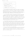
MP/M TM
Multi-Programming Monitor Control Program
USER'S GUIDE
Copyright (c) 1979, 1980
Digital Research
P.O. Box 579
801 Lighthouse Avenue
Pacific Grove, CA 93950
(408) 649-3896
TWX 910 360 5001
All Rights Reserved Digital Research 1980
MP/M User's Guide
COPYRIGHT
Copyright (c) 1979 by Digital Research. All rights
reserved. No part of this publication may be
reproduced, transmitted, transcribed, stored in a
retrieval system, or translated into any language or
computer language, in any form or by any means,
electronic, mechanical, maqnetic, optical , chemical,
manual or otherwise, without the prior written
permission of Digital Research, Post Office Box 579,
Pacific Grove, California, 93950.
This manual is, however, tutorial, in nature. Thus,
the reader is granted permission to include the
example programs, either in whole or in part, in his
own programs.
DISCLAIMER
Diqital Research makes no representations or
warranties with respect to the contents hereof and
specifically disclaims any implied warranties of
merchantability or fitness for any particular
purpose. Further, Digital Research reserves the
right to revise this publication and to make changes
from time to time in the content hereof without
obligation of Digital Research to notify any person
of such revision or changes.
Fourth Printing: July 1981
II
(All Information Herein is Proprietary to Digital Research.)
MP/M User's Guide
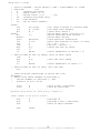
Table of Contents
1.
MP/M Features and Facilities . . . . . .
1.1
Introduction . . . . . . . . . . .
1.2
Functional Description of MP/M . .
1.3
Console Commands . . . . . . . . .
1.4
Commonly Used System Programs . .
1.5
Standard Resident System Processes
2.
MP/M Interface Guide . . . . . . . . . . . . . . . . . . 17
2.1
2.2
2.3
2.4
2.5
2.6
3.
.
.
.
.
.
.
.
.
.
.
.
.
.
.
.
.
.
.
.
.
.
.
.
.
Introduction . . . . . . . . . . . . . . . .
Basic Disk Operating System Functions . . .
Queue and Process Descriptor Data Structures
Extended Disk Operating System Functions . .
Preparation of Page Relocatable Programs . .
Installation of Resident System Processes .
MP/M Alteration Guide
3.1
3.2
3.3
3.4
3.5
3.6
.
.
.
.
.
.
.
.
.
.
.
.
.
.
.
.
.
.
.
.
.
.
.
.
.
.
.
.
.
.
. 1
. 1
. 3
. 4
. 8
. 13
.
.
.
.
.
.
17
29
53
62
81
83
. . . . . . . . . . . . . . . . . 85
Introduction . . . . . . . . . .
Basic I/0 System Entry Points .
Extended I/0 System Entry Points
System
File Components . . . .
System Generation . . . . . . .
MP/M Loader. . . . . . . . . . .
.
.
.
.
.
.
.
.
.
.
.
.
.
.
.
.
.
.
.
.
.
.
.
.
.
.
.
.
.
.
.
.
.
.
.
.
III
(All Information Herein is Proprietary to Digital Research.)
.
.
.
.
.
.
. . 85
. . 96
. 102
. 107
. 110
. 114
MP/M User's Guide
Appendix
A.
Flag Assignments . . . . . . . . . . . . . . . . . 116
B.
Process Priority Assignments . . . . . . . . . . . 117
C.
BDOS Function Summary
. . . . . . . . . . . . . . 118
D.
XDOS Function Summary
. . . . . . . . . . . . . . 119
E.
Memory Segment Base Page Reserved Locations
F.
Operation of MP/M on the Intel MDS-800 . . . . . . 121
G.
Sample Page Relocatable Program
H.
Sample Resident System Process . . . . . . . . . . 127
I.
Sample XIOS
J.
MP/M DDT Enhancements
K.
Page Relocatable (PRL) File Specification
. . . 120
. . . . . . . . . 122
. . . . . . . . . . . . . . . . . . . 131
. . . . . . . . . . . . . . 148
. . . . 149
IV
(All Information Herein is Proprietary to Digital Research.)
MP/M User's Guide
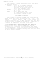
FOREWORD
This manual is intended as a guide for three different
levels of MP/M users. Section 1 contains all the information
required to enable a person to operate applications programs
running under the MP/M Operating System. Thus, the first section
of this manual should enable the casual user to operate the
system with a minimum amount of study and training.
The second section of this manual describes the MP/M system
organization including the structure of memory and system call
functions. The intention is to provide the necessary information
required to write page relocatable programs and resident system
processes which operate under MP/M, and which use the real-time
multi-tasking, peripheral and disk I/O facilities of the system.
The last section provides the information needed to tailor
MP/M to another computer system. In particular, the hardware
dependent basic and extended I/O system entry points are
described. Preparation of the MP/M loader using a CP/M 2.0 BIOS
is also covered.
The system generation procedure is also described in the
last section. This procedure is of interest to all three levels
of MP/M users because it describes how to configure MP/M for a
particular applications environment. This configuration includes
the specification of memory segmentation, number of consoles, and
selection optional resident system processes such as the printer
spooler.
V
(All Information Herein is Proprietary to Digital Research.)
MP/M User's Guide
This page was intentionally left blank.
VI
(All Information Herein is Proprietary to Digital Research.)
MP/M User's Guide
1.
MP/M FEATURES AND FACILITIES
1.1
Introduction
The purpose of the MP/M multi-programming monitor control
program is to provide a microcomputer operating system which
supports multi-terminal access with multi-programming at each
terminal.
OVERVIEW
The MP/M operating system is an upward compatible version
of CP/M 2.0 with a number of added facilities. These added
facilities are contained in new logical sections of MP/M called
the extended I/O system and the extended disk operating system.
In this manual the name XIOS will refer to the combined basic and
extended I/O system. BDOS will refer to the standard CP/M 2.0
basic disk operating system functions and XDOS will refer to the
extended disk operating system. As an upward compatible version,
users can easily make the transition from CP/M to the MP/M
operating system. In fact, existing CP/M *.COM files can be run
under MP/M, providing that the program has been correctly
written. That is, BDOS calls are made for I/O, and the only
direct BIOS calls made are for console and printer I/O. There
must also be at least 4 bytes of extra stack in the CP/M *.COM
program.
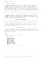
The following basic facilities are provided:
o multi-terminal support
o Multi-Programming at each terminal
o Support for bank switched memory and
memory protection
o Concurrency of I/0 and CPU operations
o Interprocess communication, mutual
exclusion and synchronization
o Ability to operate in sequential, polled
or interrupt driven environments
o System timing functions
o Logical interrupt system utilizing flags
o Selection of system options at system
generation time
o Dynamic system configuration at load time
The following optional facilities are provided:
o
o
o
o
Spooling list files
Scheduling programs
Displaying complete
Setting and reading
to the printer
to be run by date and time
system run-time status
of the date and time
1
(All Information Herein is Proprietary to Digital Research.)
MP/M User's Guide
HARDWARE ENVIRONMENT
The hardware environment for MP/M must include an 8080 or
Z80 CPU, a minimum of 32K bytes of memory, 1 to 16 consoles, 1 to
16 logical (or physical) disk drives each containing up to eight
megabytes, and a clock/timer interrupt.
The distributed form of the MP/M operating system is
configured for a polled I/O environment on the Intel MDS-800 with
two consoles and a real-time clock. Multi-programming at two
terminals is supported with this configuration. To improve the
system performance and capability the following incremental
hardware additions can be utilized by the operating system:
a. Full Interrupt System
b. Banked Memory
c. Additional Consoles
MEMORY SIZE
The MP/M operating system requires less than 15K bytes of
memory when configured for two consoles and eight memory segments
on the Intel MDS-800. Each additional console requires 256
bytes.
Optional resident system processes can be specified at
system generation which require varying amounts of memory.
PERFORMANCE
When MP/M is configured for a single console and is
executing a single process, its speed approximates that of CP/M.
In environments where either multiple processes and/or users are
running, the speed of each individual process is degraded in
proportion to the amount of I/O and compute resources required.
A process which performs a large amount of I/O in proportion to
computing exhibits only minor speed degradation. This also
applies to a process that performs a large amount of computing,
but is running concurrently with other processes that are largely
I/O bound. On the other hand, significant speed degradation
occurs in environments in which more than one compute bound
process is running.
2
(All Information Herein is Proprietary to Digital Research.)
MP/M User's Guide
1.2
Functional Description of MP/M
The MP/M Operating System is based on a real-time
multi-tasking
nucleus. This nucleus
provides process
dispatching, queue management, flag management, memory management
and system timing functions.
MP/M is a priority driven system. This means that the
highest priority ready process is given the CPU resource. The
operation of determining the highest priority ready process and
then giving it the CPU is called dispatching. Each process in
the system has a process descriptor. The purpose of the process
descriptor is to provide a data structure which contains all the
information the system needs to know about a process. This
information is used during dispatching to save the state of the
currently running process, to determine which process is to be
run, and then to restore that processes state. Process
dispatching is performed at each system call, at each interrupt,
and at each tick of the system clock. Processes with the same
priority are "round-robin" scheduled. That is, they are given
equal slices of CPU time.
Queues perform several critical functions in a real-time
multi-tasking environment. They can be used for the
communication of messages between processes, to synchronize
processes, and for mutual exclusion. As the name "queue"
implies, they provide a first in first out list of messages, and
as implemented in MP/M, a list of processes waiting for messages.
The flag management provided by MP/M is used to synchronize
processes by signaling a significant event. Flags provide a
logical interrupt system for MP/M which is independent of the
physical interrupt system. Flags are used to signal interrupts,
mapping an arbitrary physical interrupt environment into a
regular structure.
MP/M manages memory in pre-defined memory segments. Up to
eight memory segments of 48K can be managed by MP/M. This
management of memory is consistent with hardware environments
where memory is banked and/or protected in fixed segments.
System timing functions provide time of day, the capability
to schedule programs to be loaded from disk and executed, and the
ability to delay the execution of a process for a specified
period of time.
3
(All Information Herein is Proprietary to Digital Research.)
MP/M User's Guide
1.3
Console Commands
The purpose of this section is to describe the console
commands which make up the operator interface to the MP/M
operating system. It is important to note from the outset that
there are no system defined or built-in commands. That is, the
system has no reserved or special commands. All commands in the
system are provided by resident system processes specified during
system generation and programs residing on disk in either the
CP/M *.COM file format or in the MP/M *.PRL (page relocatable)
file format.
When MP/M is loaded from disk a configuration table and
memory segment map are displayed on console #0. When the loading
is complete each of the 1 to 16 configured consoles is a system
or master console. Additional slave consoles (maximum total of
slave and master consoles is 16) can be accessed using XDOS
system calls.
After loading, the following message is displayed on each
console:
MP/M
xA>
The 'x' shown in the prompt is the user code. At cold
start an association is made between the user code and console
number. The initial user code is equal to the console number.
For example, console #0 is initialized to user #0 and the
following prompt is displayed on console #0:
OA>
The default user code can then be changed to any desired
user code with the USER command (see USER in section 1.4). All
users have access to files with a user code of 0. Thus, system
files and programs should have a user code of 0. Caution must be
used when operating under a user code of 0 since all its files
can be accessed while operating under any other user code. In
general, user code 0 should be reserved for files which are
accessed by all users. In the event that a file with the same
name is present under user code 0 and another user code, the
first file found-in the directory will be accessed.
The 'A' in the prompt is the default (currently logged)
disk for the console. This can be changed individually at any
console by typing in a disk drive name (A,B,C,...,or P) followed
by a colon (:) when the prompt has been received. Since there
are no built-in commands, the default disk specified must
contain the desired command files (such as DIR, REN, ERA
etc.) , or each command must be preceeded by an "A:".
4
(All Information Herein is Proprietary to Digital Research.)
MP/M User's Guide
RUNNING A PROGRAM
A program is run by typing in the program name followed by
a carriage return, <cr>. some programs obtain parameters on the
same line following the program name. Characters on the line
following the program name constitute what is called the command
tail. The command tail is copied into location 0080H (relative
to the base of the memory segment in which the program resides)
and converted to upper case by the Command Line Interpreter
(CLI). The CLI also parses the command tail producing two file
control blocks at 005CH and 006CH respectively.
The programs which are provided with MP/M are described in
sections 1.4 and 1.5.
ABORTING A PROGRAM
A program may be aborted by typing a control C (^C) at the
console. The affect of the ^C is to terminate the program which
currently owns the console. Thus, a detached program cannot be
aborted with a C. A detached program must first be attached and
then aborted. A running program may also be aborted using the
ABORT command (see ABORT in section 1.5).
RUNNING A RESIDENT SYSTEM PROCESS
At the operator interface there is no difference between
running a program from disk and running a resident system
process. The actual difference is that resident system processes
do not need to be loaded from disk because they are loaded by the
MP/M loader when a system cold start is performed and remain
resident.
DETACHING FROM A PROGRAM
There are two methods for detaching from a running program.
The first is to type a control D (^D) at the console. The second
method is for a program to make an XDOS detach call.
The restriction on the former method, typing D, is that
the running program must be performing a check console status to
observe the detach request. A check console status is
automatically performed each time a user program makes a BDOS
disk function call.
ATTACHING TO A DETACHED PROGRAM
A program which is detached from a console, that is it does
not own a console, may be attached to a console by typing
'ATTACH' followed by the program name. A program may only be
attached to the console from which it was detached. If the
terminal message process (TMP) has ownership of the console and
5
(All Information Herein is Proprietary to Digital Research.)
MP/M User's Guide
the user enters a ^D, the next highest priority ready process
which is waiting for the console begins running.
LINE EDITING AND OUTPUT CONTROL
The Terminal message Process (TMP) allows certain line
editing functions while typing in command lines:
rubout
Delete the last character typed at the console,
removes and echoes the last character
ctl-C
MP/M abort program. Terminate running process.
ctl-D
MP/M detach console.
ctl-E
Physical end of line.
ctl-H
Delete the last character typed at the console,
backspaces one character position.
ctl-j
(line feed) terminate current input.
ctl-M
(carriage return) terminates input.
ctl-R
Retype current command line: types a "clean line"
following character deletion with rubouts.
ctl-U
Remove current line after new line.
ctl-X
Delete the entire line typed at the console,
backspaces to the beginning of the current line
ctl-Z
End input from the console.
The control functions ctl-P, ctl-Q and ctl-S affect console
output as shown below.
ctl-P
Copy all subsequent console output to the list
device. Output is sent to both the list device
and the console device until the next ctl-P
is typed. If the list device is not available
a 'Printer busy' message is displayed on the
console.
ctl-Q
Obtain ownership of the printer mutual exclusion
message. Obtaining the printer using this command
will ensure that the MP/M spooler, PIP, and other
ctl-P or ctl-Q commands entered from other
consoles will not be allowed access to the
printer. The printer is "owned" by the TMP until
another ctl-P or ctl-Q is entered, releasing the
printer. The ctl-P should be used when a program
(such as a CP/M *.COM file) is executed that does
6
(All Information Herein is Proprietary to Digital Research.)
MP/M User's Guide
not obtain the printer mutual exclusion message
prior to accessing the printer. If the list
device is not available a 'Printer busy' message
is displayed on the console.
ctl-S
Stop the console output temporarily. Program
execution and output continue when the next
character is typed at the console (e.g., another
ctl-S). This feature is used to stop output on
high speed consoles, such as CRT's, in order to
view a segment of output before continuing.
7
(All Information Herein is Proprietary to Digital Research.)
MP/M User's Guide
1.4
Commonly Used System Programs
The commonly used system programs (CUSPs) or transient
commands, as they are called in CP/M, are loaded from the
currently logged disk and executed in a relocatable memory
segment if their type is PRL or in an absolute TPA if their type
is COM.
This section contains a brief description of the CUSPs.
Operation of many of the CUSPs is identical to that under CP/M.
In these cases the commands are marked with an asterisk '*' and
the reader is referred to the Digital Research document titled
"An Introduction to CP/M Features and Facilities" for a complete
description of the CUSP.
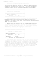
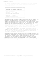
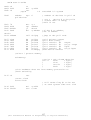
GET/SET USER CODE
The USER
as well as to
followed by a
the user code
command is used to display the current user code
set the user code value. Entering the command USER
<cr> will display the current user code. Note that
is already displayed in the prompt.
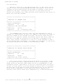
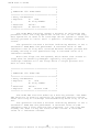
1A>user
user = 1
Entering the command USER followed by a space, a user code
and then a <cr> will set the user code to the specified user
code. Legal user codes are in the range 0 to 15.
1A>user 3
user = 3
3A>
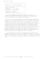
CONSOLE
The CONSOLE command is used to determine the console number
at which the command is entered. The console number is sometimes
of interest when examining the system status to determine the
processes which are detached from consoles.
1A>console
Console = 0
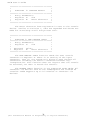
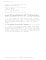
DISK RESET
The DSKRESET (disk reset) command is used to enable the
operator to change disks. If no parameter is entered all the
drives are reset. Specific drives to be reset may be included
as parameters.
1A>DSKRESET
8
(All Information Herein is Proprietary to Digital Research.)
MP/M User's Guide
1A>DSKRESET B:,E:
If there are any open files on the drive(s) to be reset,
the disk reset is denied and the cause of the disk reset
failure is shown:
1A>DSKRESET B:
Disk reset denied, Drive B: Console 0 Program Ed
The reason that disk reset is treated so carefully is that
files left open (e.g.- in the process of being written) will lose
their updated information if they are not closed prior to a disk
reset.
ERASE FILE *
The ERA (erase) command removes specified files having the
current user code. If no files can be found on the selected
diskette which satisfy the erase request, then the message "No
file" is displayed at the console.
An attempt to erase all files,
2B>ERA *.*
will produce the following response from ERA:
Confirm delete all user files (Y/N)?
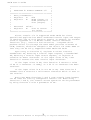
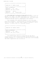
A second form of the erase command(ERAQ)
enables
operator to
selectively delete files that match
the
specified filename reference. For example:
OA>ERAQ *.LST
A:XIOS
A:MYFILE
the
LST? y
LST? N
TYPE A FILE *
The TYPE command displays the contents of the specified
ASCII source file on the console device. The TYPE command
expands tabs (ctl-I characters), assuming tab positions are set
at every eighth column.
The TYPE command has a pause mode which is specified by
entering a 'P' followed by two decimal digits after the
filename. For example:
0A>TYPE DUMP.ASM P23
9
(All Information Herein is Proprietary to Digital Research.)
MP/M User's Guide
The specified number of lines will be displayed and then TYPE
will pause until a <cr> is entered.
The TYPE program is small and relatively slow because it
buffers only one sector at a time. The larger PIP program can
be used for faster displays in the following manner:
OA>PIP CON:=MYFILE.TEX
FILE DIRECTORY *
The DIR (directory) command causes the names of files on
the specified or logged-in disk to be listed on the console
device. If no files can be found on the selected diskette which
satisfy the directory request, then the message "Not found" is
typed at the console.
The DIR command can include files which have the system
attribute set. This is done by using the 'S' option. For
example:
OA>DIR *.COM S
RENAME FILE *
The REN (rename) command allows the user to change the name
of files on disk. If the destination filename exists the
operator is given the option of deleting the current destination
file before renaming the source file.
TEXT EDITOR *
The ED (editor) command allows the user to edit ASCII text
files.
PERIPHERAL INTERCHANGE PROGRAM *
The PIP (peripheral interchange program) command allows the
user to perform disk file and peripheral transfer operations.
See the Digital Research document titled "CP/M 2.0 User's Guide
for CP/M 1.4 Owners" for a detailed description of new PIP
operations.
ASSEMBLER *
The ASM (assembler) command allows the user to assemble the
specified program on disk.
SUBMIT *
The SUBMIT command allows the user to submit a file of
commands for batch processing.
10
(All Information Herein is Proprietary to Digital Research.)
MP/M User's Guide
STATUS *
The STAT (status) command provides general statistical
information about the file storage. See the Digital Research
document titled "CP/M 2.0 User's Guide for CP/M 1.4 Owners" for a
detailed description of new STAT operations.
DUMP *
The DUMP command types the contents of the specified disk
file on the console in hexadecimal form.
LOAD *
The LOAD command reads the specified disk file of type HEX
and produces a memory image file of type COM which can
subsequently be executed.
GENMOD
The GENMOD command accepts a file which contains two
concatenated files of type HEX which are offset from each other
by 0100H bytes, and produces a file of type PRL (page
relocatable) . The form of the GENMOD command is as follows:
1A>genmod b:file.hex b:file.prl $1000
The first parameter is the file which contains two concatenated
files of type HEX. The second parameter is the name of the
destination file of type PRL. The optional third parameter is a
specification of additional memory required by the program beyond
the explicit code space. The form of the third parameter is a
'$' followed by four hex ASCII digits. For example, if the
program has been written to use all of 'available' memory for
buffers, specification of the third parameter will ensure a
minimum buffer allocation.
GENHEX
The GENHEX command is used to produce a file of type HEX
from a file of type COM. This is useful to be able to
generate HEX files for GENMOD input. The GENHEX command has
two parameters, the first is the COM file name and the second is
the offset for the HEX file. For example:
OA>GENHEX PROG.COM 100
PRLCOM
The PRLCOM command accepts a file of PRL type and produces
a file of COM type. If the destination COM file exists, a query
is made to determine if the file should be deleted before
continuing.
11
(All Information Herein is Proprietary to Digital Research.)
MP/M User's Guide
OA>prlcom b:program.prl a:program.com
DYNAMIC DEBUGGING TOOL *
The DDT (dynamic debugging tool) command loads and executes
the MP/M debugger. In systems with banked memory multiple DDT
programs can be running concurrently in absolute TPAs. A PRL
(relocatable) version of DDT is also provided which enables
multiple DDTs to run in a non-banked system. The name of the
relocatable DDT is RDT.
MP/M DDT enhancements are described in Appendix J.
12
(All Information Herein is Proprietary to Digital Research.)
MP/M User's Guide
1.5
Standard Resident System Processes
The standard resident system processes (RSPs) are new
programs specifically designed to facilitate use of the MP/M
operating system. The RSPs may either be present on disk as
files of the PRL type, or they may be resident system processes.
Resident system processes are selected at the time of system
generation.
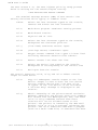
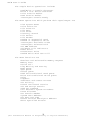
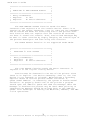
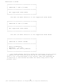
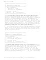
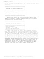
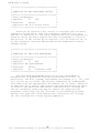
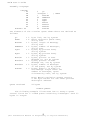
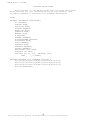
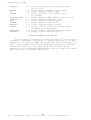
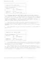
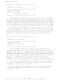
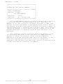
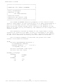
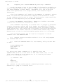
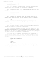
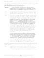
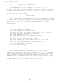
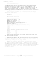
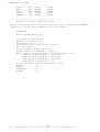
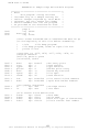
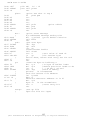
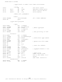
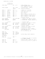
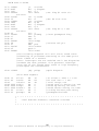
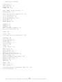
SYSTEM STATUS
The MPMSTAT command allows the user to display the run-time
status of the MP/M operating system. MPMSTAT is invoked by
typing 'MPMSTAT’ followed by a <cr>. A sample MPMSTAT output is
shown below:
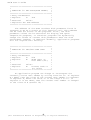
****** MP/M Status Display ******
Top of memory = FFFFH
Number of consoles = 02
Debugger breakpoint restart # = 06
Stack is swapped on BDOS calls
Z80 complementary registers managed by dispatcher
Ready Process(es)
MPMSTAT
Idle
Process(es) DQing:
[Sched
]
Sched
[ATTACH
]
ATTACH
[CliQ
]
cli
Process(es) NQing:
Delayed Process(es):
Polling Process (es)
PIP
Process(es) Flag Waiting:
01 - Tick
02 - Clock
Flag(s) Set:
03
Queue(s):
MPMSTAT
Sched
CliQ ATTACH
MXParse
MXList
[TmpO
]MXDisk
Process(es) Attached to Consoles:
[0] - MPMSTAT
[1] - PIP
Process(es) Waiting for Consoles:
[0] - TMPO
DIR
[1] - TMPl
Memory Allocation:
Base = OOOOH
Size = 4000H
Allocated to PIP
Base = 4000H
Size = 2000H * Free *
Base = 6000H
Size = 1100H
Allocated to DIR
13
(All Information Herein is Proprietary to Digital Research.)
[1]
[0]
MP/M User's Guide
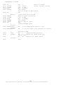
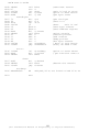
The MP/M status display is intepreted as follows:
Ready Process (es): The ready processes are those
processes which are ready to run and are waiting for the
CPU. The list of ready processes is ordered by the
priority of the processes and includes the console number
at which the process was initiated. The highest priority
ready process is the running process.
Process(es) DQing: The processes DQing are those
processes which are waiting for messages to be written to
the specified queue. The queue name is in brackets
followed by the names of processes, in priority order,
which have executed read queue operations on the queue.
Process(es) NQing: The processes NQing are those
processes which are waiting for an available buffer to
write a message to the specified queue. The queue name is
in brackets followed by the names of the processes, in
priority order, which are waiting for buffers.
Delayed Process(es): The delayed processes are those
which are delaying for a specified number of ticks of the
system time unit.
Polling Process(es): The polling processes are those
which are polling a specified I/O device for a device ready
status.
Process(es) Flag Waiting: The processes flag waiting
are listed by flag number and process name.
Flag(s) Set: The flags which are set are displayed.
Queue(s): All the queues in the system are listed by
queue name. Queue names which are all in capital letters
are accessible by command line interpreter input. For
example, the SPOOL queue can be sent a message to spool a
file by entering 'SPOOL' followed by a file name.
Processes DQing from queues which have a name that matches
the process name are given the console resource when they
receive a message. Queue names that begin with 'MX' are
called mutual exclusion queues. The display of a mutual
exclusion queue includes the name of the process, if any,
which has the mutual exclusion message.
Process(es) Attached to Consoles: The process
attached to each console is listed by console number and
process name.
Process(es) Waiting for. Consoles: The processes
waiting for each console are listed by console number and
process name in priority order. They are processes which
14
(All Information Herein is Proprietary to Digital Research.)
MP/M User's Guide
have detached from the console and are then waiting for the
console before they can continue execution.
Memory Allocation: The memory allocation map shows
the base, size, bank, and allocation of each memory
segment. Segments which are not allocated are shown as '*
Free *', while allocated segments are identified by process
name and the console in brackets associated with the
process. Memory segments which are set as pre-allocated
during system generation by specifying an attribute of OFFH
are shown as Reserved
SPOOLER
The SPOOL command allows the
to the list device. Multiple file
command tail. The spooler expands
assuming tab positions are set at
user to spool ASCII text files
names may be specified in the
tabs (ctl-I characters),
every eighth column.
The spooler queue can be purged at any time by using the
STOPSPLR command.
An example of the SPOOL command is shown below:
1A>SPOOL LOAD.LST,LETTER.PRN
The non-resident version of the spooler (SPOOL.PRL) differs
in its operation from the SPOOL.RSP as follows: it uses all of
the memory available in the memory segment in which it is
running for buffer space; it displays a message
indicating its status and then detaches from the console; it
may be aborted from a console other than the initiator only by
specifying the console number of the initiator as a parameter of
the STOPSPLR command.
3B>STOPSPLR 2
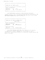
DATE AND TIME
The TOD (time of day) command allows the user to read and
set the date and time. Entering 'TOD' followed by a <cr> will
cause the current date and time to be displayed on the console.
Entering 'TOD' followed by a date and time will set the date and
time when a <cr> is entered following the prompt to strike a key.
Each of these TOD commands is illustrated below:
1A>TOD <cr>
Wed 02/06/?0 09:15:37
-or1A>TOD 2/9/80 10:30:00
15
(All Information Herein is Proprietary to Digital Research.)
MP/M User's Guide
Strike key to set time
Sat 02/09/80 10:30:00
Entering 'TOD P' will cause the current time and date to be
continuously displayed until a key is struck at the console.
SCHEDULER
The SCHED (scheduler) command allows the user to schedule a
program for execution. Entering 'SCHED' followed by a date, time
and command line will cause the command line to be executed when
the specified date and time is reached.
In the example shown below, the program 'SAMPLE' will be
loaded from disk and executed on February 8, 1980 at 10:30 PM.
Note that only hours and minutes are specified, not seconds.
Programs are scheduled to the nearest minute.
1A>SCHED 2/8/79 22:30 SAMPLE
ABORT
The ABORT command allows the user to abort a running
program. The program to be aborted is entered as a
parameter in the ABORT command.
1A>ABORT RDT
A program initiated from another console may only be
aborted by including its console number as a parameter of the
ABORT command.
3B>ABORT RDT 1
16
(All Information Herein is Proprietary to Digital Research.)
MP/M User's Guide
2.
MP/M INTERFACE GUIDE
This section describes MP/M system organization including
the structure of memory and system call functions. The intention
is to provide the necessary information required to write page
relocatable programs and resident system processes which operate
under MP/M, and which use the real-time, multi-tasking,
peripheral, and disk I/O facilities of the system.
2.1
Introduction
MP/M is logically divided into several modules. The three
primary modules are named the Basic and Extended I/O System
(XIOS), the Basic Disk Operating System (BDOS), and the Extended
Disk Operating System (XDOS). The XIOS is a hardware-dependent
module which defines the exact low level interface to a
particular computer system which is necessary for peripheral
device I/O. Although a standard XIOS is supplied by Digital
Research, explicit instructions are provided for field
reconfiguration of the XIOS to match nearly any hardware
environment.
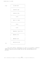
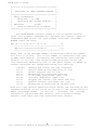
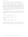
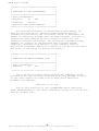
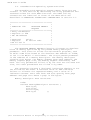
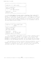
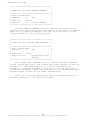
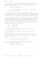
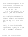
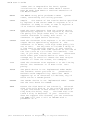
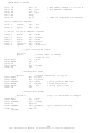
MP/M
memory structure is shown below:
17
(All Information Herein is Proprietary to Digital Research.)
MP/M User's Guide
high
low
--------------------------:
:
:
SYSTEM.DAT
:
:
:
--------------------------:
:
:
CONSOLE.DAT
:
:
:
--------------------------:
:
:
USERSYS.STK
:
:
:
--------------------------:
:
:
XIOS
:
:
:
--------------------------:
:
:
BDOS or ODOS
:
:
:
--------------------------:
:
:
XDOS
:
:
:
--------------------------:
:
:
RSPs
:
:
:
--------------------------:
:
:
BNKBDOS (Optional)
:
:
:
--------------------------:
:
:
MEMSEG.USR
:
:
:
. . .
:
:
:
MEMSEG.USR
:
:
:
--------------------------:
:
:
ABSOLUTE TPA
:
:
:
---------------------------
The exact memory addresses for each of the memory segments
shown above will vary with MP/M version and depend on the
operator specifications made during the system generation
process.
18
(All Information Herein is Proprietary to Digital Research.)
MP/M User's Guide
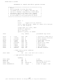
The memory segments are described as follows:
SYSTEM.DAT
The SYSTEM.DAT segment contains 256 bytes
used by the loader to dynamically configure the
system. After loading, the segment is used for
storage of system data such as submit flags. See
section 3.4 under SYSTEM DATA for a detailed
description of the byte allocation.
CONSOLE.DAT
The CONSOLE.DAT segment varies in length
with the number of consoles. Each console
requires 256 bytes which contains the TMP's
process descriptor, stack and buffers.
USERSYS.STK
The USERSYS.STK segment is
optional
depending upon whether or not the user intends to
run CP/M *.COM files. This segment contains 64
bytes of stack space per user memory segment and
is used as a temporary stack when user programs
make BDOS calls.
Specification of the option to
include this segment is made during
system
generation. The size of the USERSYS.STK segment
varies as follows:
OOOH - No user system stacks
100H - 1 to 4 memory segments
200H - 5 to 8 memory segments
XIOS
The XIOS segment contains
the user
Customized basic and extended I/O system in page
relocatable format.
BDOS/ODOS
The BDOS segment contains the disk file and
multiple console management functions. The
segment is about 1400H bytes in length.
The ODOS segment contains the resident portion of
the banked BDOS file and console management
functions. The segment is about 800H bytes in
length.
XDOS
The XDOS segment contains the MP/M nucleus
and the extended disk operating system.
The
segment is about 2000H bytes in length.
RSPs
The operator makes a selection of Resident
System Processes during system generation.
The
RSPs require varying amounts of memory.
BNKBDOS (Optional) The BNKBDOS segment is present only
in systems with a bank switched BDOS. it
contains the non-resident portion of the banked
BDOS disk file management. This segment is about
EOOH bytes in length.
19
(All Information Herein is Proprietary to Digital Research.)
MP/M User's Guide
MEMSEG.USR
The user can specifiy 1 to 8 user memory
segments during the system generation process.
These memory segments may be in the same address
space with different bank numbers.
TPA
The ABSOLUTE TPA is a user memory
segment
which is based
at OOOOH. In systems with bank
switched memory
there may be more than
one
ABSOLUTE TPA.
Each user memory segment, including the TPA, is further
divided into two regions. The first is called the system
parameter area. The system parameter area occupies the first
100H bytes of the. memory segment and is defined similarily to
that of CP/M. See APPENDIX E for a detailed description of the
system parameter area. This area is also called the memory
segment base page.
The second
code area. This
memory segment.
the user memory
area.
region of the user memory segment is the user
area begins at 0100H relative to the base of the
When a program is loaded, code is placed into
segment beginning at the start of the user code
Transient programs are loaded into memory by the Command
Line Interpreter (CLI). CLI receives commands from the Terminal
Message Process (TMP) which accepts the operator console input.
The TMP is a reentrant program which is executed by as many
processes as there are system consoles. The operator
communicates with the TMP by typing command lines following each
prompt. Each command line generally takes one of the forms:
command
command filel
command filel file2
where "command" is either a queue such as SPOOL or ATTACH, or the
name of a transient command or program.
A brief discussion of CLI operation will describe the
loading of transient programs.
When CLI receives a command line it parses the first entry
on the command line and then tries to open a queue using the
parsed name. If the open queue succeeds the command tail is
written to the queue and the CLI operation is finished. If the
open queue fails, a file type of PRL is entered for the parsed
file name and a file open is attempted. If the file open
succeeds then the header of the PRL file is read to determine the
memory requirements. A relocatable memory request is made to
obtain a memory segment in which to load and run the program. if
this request is satisfied the PRL file is read into the memory
20
(All Information Herein is Proprietary to Digital Research.)
MP/M User's Guide
segment, relocated, and it is executed, completing the CLI
operation.
If the PRL file type open fails then the file type of COM
is entered for the parsed file name and a file open is attempted.
If the open succeeds then a memory request is made for an
absolute TPA, memory segment based at OOOOH. If this request is
satisfied the COM file is read into the absolute TPA and it is
executed completing the CLI operation.
If the command is followed by one or two file
specifications, the CLI prepares one or two file control block
(FCB) names in the system parameter area. These optional FCB’s
are in the form necessary to access files through MP/M BDOS
calls, and are described in the next section.
The CLI creates a process descriptor for each program which
is loaded, setting up a 20 level stack which forces a branch to
the base of the user code area of the memory segment. The
default stack is set up so that a return from the loaded program
causes a branch to the MP/M facility which terminates the
process. This stack has 19 levels available which can generally
be used by the transient program since it is sufficiently large
to handle system calls.
The transient program then begins execution, perhaps using
the I/O facilities of MP/M to communicate with the operator's
console and peripheral devices, including the disk subsystem.
The I/O system is accessed by passing a "function number" and an
"information address" to MP/M through the entry point at the
memory segment base +0005H. In the case of a disk read, for
example, the transient program sends the number corresponding to
a disk read, along with the address of an FCB to MP/M. MP/M, in
turn, performs the operation and returns with either a disk read
completion indication or an error number indicating that the disk
read was unsuccessful. The function numbers and error indicators
are given in sections 2.2 and 2.4,
OPERATING SYSTEM CALL CONVENTIONS
The purpose of this section is to provide detailed
information for performing direct operating system calls from
user programs. many of the functions listed below, however, are
more simply accessed through the I/O macro library provided with
the MAC macro assembler, and listed in the Digital Research
manual entitled "MAC Macro Assembler: Language manual and
Applications Guide."
MP/M facilities which are available for access by transient
programs fall into two general categories: simple device I/O,
disk file I/O, and the XDOS functions.
21
(All Information Herein is Proprietary to Digital Research.)
MP/M User's Guide
The simple device operations include:
Read/Write a Console Character
Write a List Device Character
Print Console Buffer
Read Console Buffer
Interrogate Console Ready
The BDOS operations which perform disk Input/Output are
Disk System Reset
Drive Selection
File Creation
File Open
File Close
Directory Search
File Delete
File Rename
Random or Sequential Read
Random or Sequential Write
Interrogate Available Disks
Interrogate Selected Disk
Set DMA Address
Set/Reset File Indicators
Reset Drive
Access/Free Drive
Random Write With Zero Fill
The XDOS functions are
Absolute and Relocatable Memory Request
Memory Free
Device Poll
Flag Waiting and Setting
Make Queue
Open Queue
Delete Queue
Read and Conditional Read Queue
Write and Conditional Write Queue
Delay
Dispatch
Terminate and Create Process
Set Priority
Attach and Detach Console
Set and Assign Console
Send CLI Command
Call Resident System Procedure
Parse Filename
Get Console Number
System Data Address
Get Date and Time
Return Process Descriptor Address
Abort Specified Process
22
(All Information Herein is Proprietary to Digital Research.)
MP/M User's Guide
As mentioned above, access to the MP/M functions is
accomplished by passing a function number and information address
through the primary entry point at location memory segment base
+0005H. In general, the function number is passed in register C
with the information address in the double byte pair DE. Single
byte values are returned in register A, with double byte values
returned in HL (a zero value. is returned when the function number
is out of range). For reasons of compatibility, register A = L
and register B = H upon return in all cases. Note that the
register passing conventions of MP/M agree with those of Intel's
PL/M systems programming language.
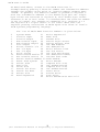
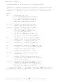
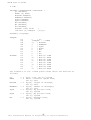
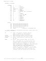
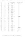
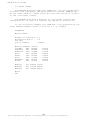
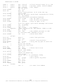
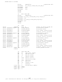
The list of MP/M BDOS function numbers is given below.
0
1
2
3
4
5
6
7
8
9
10
11
12
13
14
15
16
17
18
19
20
System Reset
21
Console Input
22
Console Output
23
Raw Console Input
24
Raw Console Output 25
List Output
26
Direct Console I/O 27
Get I/O Byte
28
Set I/O Byte
29
Print String
30
Read Console Buffer 31
Get Console Status 32
Return Version Number 33
Reset Disk System
34
Select Disk
35
Open File
36
Close File
35
Search for First
36
Search for Next
37
Delete File
38
Read Sequential
39
40
Write Sequential
Make File
Rename File
Return Login Vector
Return Current Disk
Set DMA Address
Get Addr(Alloc)
Write Protect Disk
Get R/O Vector
Set File Attributes
Get Addr(Disk Parms)
Set/Get User Code
Read Random
Write Random
Compute File Size
Set Random Record
Compute File Size
Set Random Record
Reset Drive
Access Drive
Free Drive
Write Random With Zero Fill
23
(All Information Herein is Proprietary to Digital Research.)
MP/M User's Guide
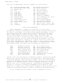
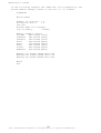
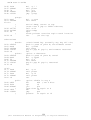
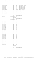
The list of MP/M XDOS function numbers is given below.
128
129
130
131
132
133
134
135
136
137
138
139
140
141
142
Absolute Memory Rqst
Relocatable Mem. Rqst
Memory Free
Poll
Flag Wait
Flag Set
Make Queue
Open Queue
Delete Queue
Read Queue
Cond. Read Queue
Write Queue
Cond. Write Queue
Delay
Dispatch
143 Terminate Process
144 Create Process
145 Set Priority
146 Attach Console
147 Detach Console
148 Set Console
149 Assign Console
150 Send CLI Command
151 Call Resident Sys. Proc.
152 Parse Filename
153 Get Console Number
154 System Data Address
155 Get Date and Time
156 Return Proc. Descr. Adr.
157 Abort Specified Process
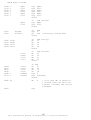
DISK FILE STRUCTURE
MP/M implements a named file structure on each disk,
providing a logical organization which allows any particular file
to contain any number of records from completely empty, to the
full capacity of the drive. Each drive is logically distinct
with a disk directory and file data area. The disk file names
are in three parts: the drive select code, the file name
consisting of one to eight non-blank characters, and the file
type consisting of zero to three non-blank characters. The file
type names the generic category of a particular file, while the
file name distinguishes individual files in each category. The
file types listed below name a few generic categories which have
been established, although they are generally arbitrary:
ASM
PRN
HEX
BAS
INT
COM
PRL
SPR
Assembler Source
Printer Listing
Hex Machine Code
Basic Source File
Intermediate Code
CCP Command File
Page Relocatable
Sys. Page Reloc.
PLI
REL
TEX
BAK
SYM
$$$
RSP
SYS
PL/I Source File
Relocatable Module
TEX Formatter Source
ED Source Backup
SID Symbol File
Temporary File
Resident Sys. Process
System File
Source files are treated as a sequence of ASCII characters, where
each "line" of the source file is followed by a carriage-return
line-feed sequence (ODH followed by OAH). Thus one 128 byte MP/M
record could contain several lines of source text. The end of an
ASCII file is denoted by a control-Z character (1AH) or a real
end of file (i.e. no more sectors), returned by the MP/M read
operation. Control-Z characters embedded within machine code
files (e.g., COM files). are ignored, however, and the end of file
condition returned by MP/M is used to terminate read operations.
Files in MP/M can be thought of as a sequence of up to
24
(All Information Herein is Proprietary to Digital Research.)
MP/M User's Guide
65536 records of 128 bytes each, numbered from 0 through 65535,
thus allowing a maximum of 8 megabytes per file. Note, however,
that although the records may be considered logically contiguous,
they are not necessarily physically contiguous in the disk data
area. Internally, all files are broken into 16K byte segments
called logical extents, so that counters are easily maintained as
8-bit values. Although the decomposition into extents is
discussed in the paragraphs which follow, they are of no
particular consequence to the programmer since each extent is
automatically accessed in both sequential and random access
modes.
In the file operations starting with function number 15, DE
usually addresses a file control block (FCB). Transient programs
often use the default file control block area reserved by MP/M at
location memory segment base +005CH for simple file operations.
The basic unit of file information is a 128 byte record used for
all file operations, thus a default location for disk I/O is
provided by MP/M at location memory segment base +0080H which is
the initial default DMA address (see function 26). All directory
operations take place in a reserved area which does not affect
write buffers as was the case in CP/M release 1, with the
exception of Search First and Search Next, where compatibility is
required.
The File Control Block (FCB) data area consists of a
sequence of 33 bytes for sequential access and a series of 36
bytes in the case that the file is accessed randomly. The
default file control block normally located at memory segment
base +005CH can be used for random access files, since the three
bytes starting at memory segment base +007DH are available for
this purpose.
25
(All Information Herein is Proprietary to Digital Research.)
MP/M User's Guide
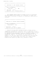
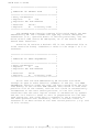
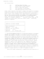
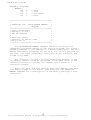
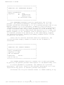
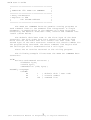
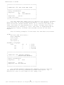
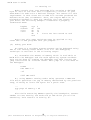
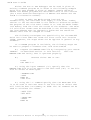
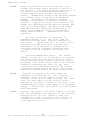
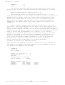
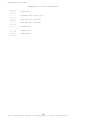
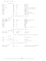
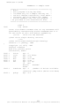
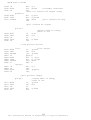
The FCB format is shown with the following fields:
------------------------------------------------------------:dr:f1:f2:/ /:f8:t1:t2:t3:ex:s1:s2:rc:d0:/ /:dn:cr:r0:r1:r2:
------------------------------------------------------------00 01 02 ... 08 09 10 11 12 13 14 15 16 ... 31 32 33 34 35
where
dr
drive code (0 - 16)
0 => use default drive for file
1 => auto disk select drive A,
2 => auto disk select drive B,
...
16=> auto disk select drive P.
fl...f8
contain the file name in ASCII
upper case, with high bit = 0
tl,t2,t3
contain the file type in ASCII
upper case, with high bit = 0
tl', t2', and t3' denote the
bit of these positions,
tl' = 1 => Read/only file,
t2' = 1 => SYS file, no DIR list
t3' = 0 => File has been updated
ex
contains the current extent number,
normally set to 00 by the user, but
in range 0 - 31 during file I/O
sl
reserved for internal system use
s2
reserved for internal system use, set
to zero on call to OPEN, MAKE, SEARCH
rc
record count for extent "ex"
takes on values from 0 – 128
d0..dn
filled-in by MP/M, reserved for
system use
cr
current record to read or write in
a sequential file operation, normally
set to zero by user
rO,rl,r2
optional random record number in the
range 0-65535, with overflow to r2,
rO,rl constitute a 16-bit value with
low byte rO, and Iiigh byte rl
Each file being
accessed
corresponding FCB which provides
through
MP/M must have a
the name and allocation
26
(All Information Herein is Proprietary to Digital Research.)
MP/M User's Guide
information for all subsequent file operations. When accessing
files, it is the programmer's responsibility to fill the lower
sixteen bytes of the FCB and initialize the "cr" field.
Normally, bytes 1 through 11 are set to the ASCII character
values for the file name and file type, while all other fields
are zero.
FCB's are stored in a directory area of the disk, and are
brought into central memory before proceeding with file
operations (see the OPEN and MAKE functions). The memory copy of
the FCB is updated as file operations take place and later
recorded permanently on disk at the termination of the file
operation (see the CLOSE command).
The CLI constructs the first sixteen bytes of two optional
FCB's for a transient by scanning the remainder of the line
following the transient name, denoted by "filel" and "file2" in
the prototype command line described above, with unspecified
fields set to ASCII blanks. The first FCB is constructed at
location memory segment base +005CH, and can be used as-is for
subsequent file operations. The second FCB occupies the dO ...
dn portion of the first FCB, and must be moved to another area of
memory before use. If, for example, the operator types
PROGNAME B:X.ZOT Y.ZAP
the file PROGNAME.PRL is loaded into a user memory segment or if
it is not on the disk, the file PROGNAME.COM is loaded into the
TPA, and the default FCB at memory segment base +005CH is
initialized to drive code 2, file name "X" and file type "ZOT".
The second drive code takes the default value 0, which is placed
at memory segment base +006CH, with the file name "Y" placed into
location memory segment base +006DH and file type "ZAP" located 8
bytes later at memory segment base +0075H. All remaining fields
through "cr" are set to zero. Note again that it is the
programmer's responsibility to move this second file name and
type to another area, usually a separate file control block,
before opening the file which begins at memory segment base
+005CH, due to the fact that the open operation will overwrite
the second name and type.
If no file names are
then the fields beginning
+006DH contain blanks. In
case alphabetics to upper
file naming conventions.
specified in the original command,
at memory segment base +005DH and
all cases, the CLI translates lower
case to be consistent with the MP/M
As an added convenience, the default buffer area at
location memory segment base +0080H is initialized to the command
line tail typed by the operator following the program name. The
first position contains the number of characters, with the
characters themselves following the character count.
27
(All Information Herein is Proprietary to Digital Research.)
MP/M User's Guide
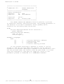
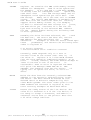
Given the above command line, the area beginning at memory
segment base +0080H is initialized as follows:
Memory Segment Base +008OH:
+00 +01 +02 +03 +04 +05 +06 +07 +08 +09 +10 +11 +12 +13 +14
14 “ “ “B” “:” “X” “.” “Z” “O” “T” “ “ “Y” “.” “Z” “A” “P”
where the characters are translated to upper case ASCII with
uninitialized memory following the last valid character. Again,
it is the responsibility of the programmer to extract the
information from this buffer before any file operations are
performed, unless the default DMA address is explicitly changed.
The individual functions are described in detail in the
sections which follow.
28
(All Information Herein is Proprietary to Digital Research.)
MP/M User's Guide
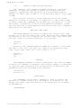
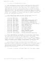
2.2 Basic Disk operating System Functions
In
general, the Basic Disk Operating System (BDOS)
facilities are identical to that of CP/M 2.0. Each function is
covered in this section by describing
the entry parameters,
returned values, and any differences between CP/M and MP/M.
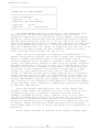
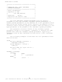
***************************************
*
*
*
FUNCTION 0: SYSTEM RESET
*
*
*
***************************************
*
Entry Parameters:
*
*
Register
C:
00H
*
***************************************
The SYSTEM RESET function terminates the calling program,
releasing the memory segment, console, and mutual exclusion
messages owned by the calling program. When the console is
released it is usually given back to the terminal message process
(TMP) for that console.
Effectively the operation of the SYSTEM RESET function is
the same for MP/M as it is for CP/M 2.0 because the program
is terminated and the operator receives the prompt to enter
another command. However, MP/M does not re-initialize the disk
subsystem by selecting and logging-in disk drive A.
***************************************
*
*
*
FUNCTION 1:. CONSOLE INPUT
*
*
*
***************************************
* Entry Parameters:
*
*
Register
C:
01H
*
*
*
* Returned
Value:
*
*
Register A: ASCII Character *
***************************************
The CONSOLE INPUT function reads the next console character
to register A. Graphic characters, along with carriage return,
line feed, and backspace (ctl-H) are echoed to the console. Tab
characters (ctl-I) are expanded in columns of eight characters.
A check is made for start/stop scroll (ctl-S) and start/stop
printer echo (ctl-P). The BDOS does not return to the calling
program until a character. has been typed, thus suspending
execution if a character is not ready.
29
(All Information Herein is Proprietary to Digital Research.)
MP/M User's Guide
***************************************
*
*
*
FUNCTION 2: CONSOLE OUTPUT
*
*
*
***************************************
*
Entry Parameters:
*
*
Register C:
02H
*
*
Register E:
ASCII Character
*
*
*
***************************************
The ASCII character from register-E is sent to the console
device. Similar to function 1, tabs are expanded and checks are
made for start/stop scroll and printer echo.
***************************************
*
*
*
FUNCTION 3: RAW CONSOLE INPUT
*
***************************************
*
Entry Parameters:
*
*
Register C:
03H
*
*
*
*
Returned
Value:
*
*
Register
A:
ASCII Character
*
***************************************
The RAW CONSOLE INPUT function reads the next console
character to Register A. There is no testing of the input
character, that is, the system wi11 directly pass through all
characters including the control characters without any
interpretation. This function does not require that the console
be attached, nor does it attach the console.
The READER INPUT function is not supported under MP/M. All
character I/O devices such as the reader/punch are treated as
consoles. MP/M supports up to 16 consoles or character I/O
devices.
30
(All Information Herein is Proprietary to Digital Research.)
MP/M User's Guide
***************************************
*
*
* FUNCTION 4: RAW CONSOLE OUTPUT
*
*
*
***************************************
* Entry Parameters:
*
* Register
C: 04H
*
* Register
E: ASCII Character
*
*
*
***************************************
The RAW CONSOLE OUTPUT function sends the ASCII
character from register E to the console device. There is no
testing of the output character, that is, tabs are not expanded
and no checks are made for start/stop scroll and printer echo.
This function does not require that the console be attached,
nor does it attach the console. Thus, unsolicited messages may
be sent to other consoles by simply changing the console byte of
the process descriptor and then using this function.
The PUNCH OUTPUT function is not supported under MP/M.
***************************************
*
*
*
FUNCTION 5: LIST OUTPUT
*
*
*
***************************************
*
Entry Parameters:
*
*
Register
C: 05H
*
*
Register
E: ASCII Character
*
*
*
***************************************
The LIST OUTPUT function sends the ASCII character in
register E to the logical listing device.
Caution must be observed in the use of the printer since
there is no implicit list device ownership. That is, the list
device is not "opened" or "closed". MP/M affords a secondary
explicit means to resolve printer mutual exclusion. A
queue named 'MXList' is created by the system to handle mutual
exclusion. To properly obtain use of the printer a program
should open the 'MXList' queue and read the message. When the
message is obtained the printer may be used. When printing is
completed the message should be written back to the 'MXList'
queue. This technique is used by the MP/M PIP, SPOOLer, and TMP
c-tl-P operations.
31
(All Information Herein is Proprietary to Digital Research.)
MP/M User's Guide
***************************************
*
*
*
FUNCTION 6: DIRECT CONSOLE I/0
*
*
*
***************************************
*
Entry Parameters:
*
*
Register
C:
06H
*
*
Register
E:
OFFH (input) or
*
*
0FEH (status)or
*
*
char (output)
*
*
*
*
Returned
Value:
*
*
Register
A:
char or status
*
*
(no value)
*
***************************************
Direct console I/O is supported under MP/M for those
specialized applications where unadorned console input and output
is required. Use of this function should, in general, be avoided
since it bypasses all of MP/M's normal control character
functions (e.g., control-S and control-P) . Programs which
perform direct I/O through the BIOS under previous releases of
CP/M, however, should be changed to use direct I/O under BDOS so
that they can be fully supported under MP/M and CP/M.
Upon entry to function 6, register E either contains
hexadecimal FF, denoting a console input request, a hexadecimal
FE, denoting a console input status request, or register E
contains an ASCII character. If the input value is FF, then
function 6 returns the next console input character.
If the input value is FE, then function 6 returns a value
of FF if a character is ready, or a 00 if no character has been
received.
If the input value in E is not FF or FE, then function 6
assumes that E contains a valid ASCII character which is sent to
the console.
Note that BDOS functions 3 and 4 (raw console input/output)
can be used for totally transparent console I/O. When using
functions 3 and 4, the console status operation can be performed
by using function 6 with a parameter of FE.
32
(All Information Herein is Proprietary to Digital Research.)
MP/M User's Guide
***************************************
*
*
* FUNCTION 7: GET I/O BYTE
*
*
*
***************************************
*
*
* Not supported under MP/M
*
*
*
***************************************
The GET I/O BYTE function is not supported under MP/M.
***************************************
*
*
* FUNCTION 8: SET I/O BYTE
*
*
*
***************************************
*
*
* Not supported under MP/M
*
*
*
***************************************
The SET I/O BYTE function is not supported under MP/M.
***************************************
*
*
* FUNCTION 9: PRINT STRING
*
*
*
***************************************
*
*
* Entry Parameters:
*
* Register
C: 09H
*
* Registers DE: String Address
*
*
*
***************************************
The PRINT STRING function sends the character string stored
in memory at the location given by DE to the console device,
until a “$" is encountered in the string. Tabs are expanded as
in function 2, and checks are made for start/stop scroll and
printer echo.
33
(All Information Herein is Proprietary to Digital Research.)
MP/M User's Guide
***************************************
*
*
*
FUNCTION 10: READ CONSOLE BUFFER *
*
*
***************************************
* Entry Parameters:
*
*
Register
C: OAH
*
*
Registers DE: Buffer Address
*
*
*
* Returned
Value:
*
*
Console Characters in Buffer
*
***************************************
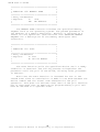
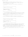
The READ BUFFER function reads a line of edited console
input into a buffer addressed by registers DE. Console input is
terminated when either the input buffer overflows. The READ
BUFFER takes the form:
DE: +0 +1 +2 +3 +4 +5 +6 +7 +8
. . .
+n
-----------------------------------------:mx:nc:c1:c2:c3:c4:c5:c6:c7:
. . . :??:
-----------------------------------------where "mx" is the maximum number of characters which the buffer
will hold (1 to 255), "nc" is the number of characters read (set
by BDOS upon return), followed by the characters read from the
console. if nc < mx, then uninitialized positions follow the
last character, denoted by "??" in the above figure. A number of
control functions are recognized during line editing:
rub/del
ctl-C
ctl-E
ctl-H
ctl-J
ctl-M
ctl-R
ctl-U
ctl-X
removes and echoes the last character
reboots when at the beginning of line
causes physical end of line
backspaces one character position
(line feed) terminates input line
(return) terminates input line
retypes the current line after new line
removes current line after new line
backspaces to beginning of current line
Note also that certain functions which return the carriage to the
leftmost position (e.g., ctl-X) do so only to the column position
where the prompt ended
(in earlier
releases, the carriage
returned to the extreme left margin). This convention makes
operator data input and line correction more legible.
34
(All Information Herein is Proprietary to Digital Research.)
MP/M User's Guide
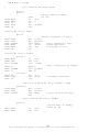
***************************************
*
*
*
FUNCTION 11: GET CONSOLE STATUS
*
*
*
***************************************
*
Entry Parameters:
*
*
Register
C:
OBH
*
*
*
*
Returned
Value:
*
*
Register
A:
Console Status
*
***************************************
The CONSOLE STATUS function checks to see if a character
has been typed at the console. If a character is ready, the
value OFFH is returned in register A. Otherwise a OOH value is
returned.
***************************************
*
*
* FUNCTION 12: RETURN VERSION NUMBER *
*
*
***************************************
*
Entry Parameters:
*
*
Register C:
OCH
*
*
*
* Returned
Value:
*
* Registers HL: Version Number
*
***************************************
Function 12 provides information which allows version
independent programming. A two-byte value is returned, with H =
00 designating the CP/M release (H = 01 for MP/M), and L = 00 for
all releases previous to 2.0. CP/M 2.0 returns a hexadecimal 20
in register L, with subsequent version 2 releases in the
hexadecimal range 21, 22, through 2F. Using function 12, for
example, you can write application programs which provide both
sequential and random access functions, with random access
disabled when operating under early releases of CP/M.
35
(All Information Herein is Proprietary to Digital Research.)
MP/M User's Guide
***************************************
*
*
*
FUNCTION 13: RESET DISK SYSTEM
*
*
*
***************************************
*
Entry Parameters:
*
*
Register C:
ODH
*
*
*
*
Returned Value:
*
*
Register
A:
Return Code
*
***************************************
The RESET DISK function is used to programmatically restore
the file system to a reset state where all disks are set to
read/write (see functions 28 and 29), and the default DMA address
is reset to the memory segment base +0080H. This function can be
used, for example, by an application program which requires a
disk change without a system reboot.
The RESET DISK SYSTEM function is qualified in MP/M. if
there are any open files on any drive, the reset disk system
is denied and the reason is displayed on the console. The
returned value indicates whether or not the reset disk was
successful. If any process is currently accessing a drive, an
error code of OFFH is returned in the A register. A return code
of 0 indicates success.
***************************************
*
*
*
FUNCTION 14: SELECT DISK
*
*
*
***************************************
* Entry Parameters:
*
*
*
*
Register
C:
OEH
*
*
Register
E:
Selected Disk
*
*
*
***************************************
The SELECT DISK function designates the disk drive named in
register E as the default disk for subsequent file operations,
with E = 0 for drive A, 1 for drive B, and so-forth through 15
corresponding to drive P in a full sixteen drive system. The
drive is placed in an "on-line" status which, in particular,
activates its directory until the next cold start, warm start, or
disk system reset operation. If the disk media is changed while
it is on-line, the drive automatically goes to a read/only status
in a standard MP/M environment (see function 28). FCB's which
specify drive code zero (dr = OOH) automatically reference the
currently selected default drive. Drive code values between 1
and 16, however, ignore the selected default drive and directly
reference drives A through P.
36
(All Information Herein is Proprietary to Digital Research.)
MP/M User's Guide
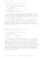
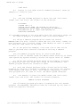
***************************************
*
*
*
FUNCTION 15: OPEN FILE
*
*
*
***************************************
*
Entry Parameters:
*
*
Register
C:
OFH
*
*
Registers DE: FCB Address
*
*
*
*
Returned Value:
*
*
Register A:
Directory Code
*
***************************************
The OPEN FILE operation is used to activate a file which
currently exists in the disk directory for either the currently
active user code or user code 0. The BDOS scans the referenced
disk directory for a match in positions 1 through 14 of the FCB
referenced by DE (byte sl is automatically zeroed), where an
ASCII question mark (3FH) matches any directory character in any
of these positions. Normally, no question marks are included
and, further, bytes "ex" and "s2" of the FCB are zero.
If a directory element is matched, the relevant directory
information is copied into bytes dO through dn of the FCB, thus
allowing access to the files through subsequent read and write
operations. Note that an existing file must not be accessed
until a sucessful open operation is completed. Upon return, the
open function returns a "directory code" with the value 0 through
3 if the open was successful, or OFFH (255 decimal) if the file
cannot be found. If question marks occur in the FCB then the
first matching FCB is activated. Note that the current record
("cr") must be zeroed by the program if the file is to be
accessed sequentially from the first record.
The open-file operation will succeed for files with either
the current user code or user code 0. This presents a problem
when files with the same name exist under both the current user
code and under user code 0. When such a situation exists the
first one found in the directory will be opened. Even though
this should not present a problem because user code 0 is intended
only for system and commonly used files, a potential problem can
be detected by using the search file function. The search file
function enables examination of the directory FCB and thus the
actual file user code can be determined.
Opening a file sets the appropriate bit in the drive active
vector of the calling processes process descriptor. This bit is
cleared only by terminating the process or making a free drive
(function 39) call. Setting of the bit in the drive active
vector will prevent any other process from resetting the drive on
which the file was opened.
37
(All Information Herein is Proprietary to Digital Research.)
MP/M User's Guide
***************************************
*
*
*
FUNCTION 16: CLOSE FILE
*
*
*
***************************************
*
Entry Parameters:
*
*
Register C:
10H
*
*
Registers DE: FCB Address
*
*
*
* Returned
Value:
*
* Register
A:
Directory Code
*
***************************************
The CLOSE FILE function performs the inverse of the open
file function. Given that the FCB addressed by DE has been
previously activated through an open or make function (see
functions 15 and 22), the close function permanently records the
new FCB in the referenced disk directory. The FCB matching
process for the close is identical to the open function. The
directory code returned for a successful close operation is 0, 1,
2, or 3, while a OFFH (255 decimal) is returned if the file name
cannot be found in the directory. A file need not be closed if
only read operations have taken place. If write operations have
occurred, however, the close operation is necessary to
permanently record the new directory information.
Note that the close file function does not affect the drive
active vector of the calling processes process descriptor. The
free drive function (function 39) must be used to reset the bit
of the drive active vector.
***************************************
*
*
* FUNCTION 17: SEARCH FOR FIRST
*
*
*
***************************************
* Entry Parameters:
*
*
Register C:
11H
*
*
Registers DE: FCB Address
*
*
*
*
Returned Value:
*
*
Register A:
Directory Code
*
***************************************
SEARCH FIRST scans the directory for a match with the file
given by the FCB addressed by DE. Files with either the
currently active user code or user code 0 will match. The value
255 (hexadecimal FF) is returned if the file is not found,
otherwise 0, 1, 2, or 3 is returned indicating the file is
present. In the case that the file is found, the current DMA
address is filled with the record containing the directory entry,
and the relative starting position is A * 32 (i.e., rotate the A
38
(All Information Herein is Proprietary to Digital Research.)
MP/M User's Guide
register left 5 bits, or ADD A five times). Although not
normally required for application programs, the directory
information can be extracted from the buffer at this position.
An ASCII question mark (63 decimal, 3F hexadecimal) in any
position from "fl" through "ex" matches the corresponding field
of any directory entry on the default or auto-selected disk
drive. If the "dr" field contains an ASCII question mark, then
the auto disk select function is disabled, the default disk is
searched, with the search function returning any matched entry,
allocated or free, belonging to any user number. This latter
function is not normally used by application programs, but does
allow complete flexibility to scan all current directory values.
If the "dr" field is not a question mark, the "s2" byte is
automatically zeroed.
To determine the user code of a successful search (it may
be the currently active user code or user code 0), the returned
directory code can be used as described above to index into the
DMA buffer and the user code of the directory FCB can be
obtained.
***************************************
*
*
* FUNCTION 18: SEARCH FOR NEXT
*
*
*
***************************************
* Entry Parameters:
*
* Register
C:
12H
*
*
*
* Returned
Value:
*
* Register
A:
Directory Code
*
***************************************
The SEARCH NEXT function is similar to the Search First
function, except that the directory scan continues from the last
matched entry. Similar to function 17, function 18 returns the
decimal value 255 in A when no more directory items match.
39
(All Information Herein is Proprietary to Digital Research.)
MP/M User's Guide
***************************************
*
*
* FUNCTION 19: DELETE FILE
*
*
*
***************************************
* Entry Parameters:
*
* Register
C:
13H
*
* Registers DE: FCB Address
*
*
*
* Returned
Value:
*
* Register
A:
Directory Code
*
***************************************
The DELETE FILE function removes files which match the FCB
addressed by DE. The filename and type may contain ambiguous
references (i.e., question marks in various positions), but the
drive select code cannot be ambiguous, as in the Search and
Search Next functions.
Function 19 returns a decimal 255 if the referenced file or
files cannot be found, otherwise a value in the range 0 to 3 is
returned.
***************************************
*
*
* FUNCTION 20: READ SEQUENTIAL
*
*
*
***************************************
* Entry Parameters:
*
* Register
C:
14H
*
* Registers DE: FCB Address
*
*
*
* Returned
Value
*
* Register
A:
Directory Code
*
***************************************
Given that the FCB addressed by DE has been activated
through an open or make function (numbers 15 and 22), the READ
SEQUENTIAL function reads the next 128 byte record from the file
Into memory at the current DMA address. The record is read from
position "cr" of the extent, and the "cr" field is automatically
Incremented to the next record position. If the "cr" field
overflows then the next logical extent is automaticall1y opened
and the “cr" field is reset to zero in preparation for the next
read operation. The value 00H is returned in the A register if
the read operation was successful, while a non-zero value is
returned if no data exists at the next record position ( e.g. end
of file occurs).
40
(All Information Herein is Proprietary to Digital Research.)
MP/M User's Guide
***************************************
*
*
* FUNCTION 21: WRITE SEQUENTIAL
*
*
*
***************************************
* Entry Parameters:
*
* Register
C:
15H
*
* Registers DE: FCB Address
*
*
*
* Returned
Value:
*
* Register
A:
Directory Code
*
***************************************
Given that the FCB addressed by DE has been activated
through an open or make function (numbers 15 and 22), the WRITE
SEQUENTIAL function writes the 128 byte data record at the
current DMA address to the file named by the FCB. the record is
placed at position "cr" of the file, and the "cr" field is
automatically incremented to the next record position. If the
"cr" field overflows then the next logical extent is
automatically opened and the "cr” field is reset to zero in
preparation for the next write operation. Write operations can
take place into an existing file, in which case newly written
records overlay those which already exist in the file. Register
A = OOH upon return from a successful write operation, while a
non-zero value indicates a full disk.
***************************************
*
*
* FUNCTION 22: MAKE FILE
*
*
*
***************************************
* Entry Parameters:
*
* Register
C:
16H
*
* Registers DE: FCB Address
*
*
*
* Returned
Value:
*
* Register
A:
Directory Code
*
***************************************
The MAKE FILE operation is similar to the open file
operation except that the FCB must name a file which does not
exist in the currently referenced disk directory (i.e., the one
named explicitly by a non-zero “dr" code, or the default disk if
"dr" is zero). The FDOS creates the file and initializes both
the directory and main memory value to an empty file. The
programmer must ensure that no duplicate file names occur, and a
preceding delete operation is sufficient if there is any
possibility of duplication. Upon return, register A = 0, 1, 2,
or 3 if the operation was successful and OFFH (255 decimal) if no
more directory space is available. The make function has the
side-effect of activating the FCB and thus a subsequent open is
41
(All Information Herein is Proprietary to Digital Research.)
MP/M User's Guide
not necessary.
Making a file sets the appropriate bit in the drive active
vector of the calling processes process descriptor. This bit is
cleared only by terminating the process or making a free drive
(function 39) call. Setting of the bit in the drive active
vector will prevent any other process from resetting the drive on
which the file was opened.
***************************************
*
*
* FUNCTION 23: RENAME FILE
*
*
*
***************************************
* Entry Parameters:
*
* Register
C:
17H
*
* Registers DE: FCB Address
*
*
*
* Returned
Value:
*
* Register
A:
Directory Code
*
***************************************
The RENAME FILE function uses the FCB addressed by DE to
change all occurrences of the file named in the first 16 bytes to
the file named in the second 16 bytes. The drive code "dr" at
position 0 is used to select the drive, while the drive code for
the new file name at position 16 of the FCB is assumed to be
zero. Upon return, register A is set to a value between 0 and 3
if the rename was successful, and OFFH (255 decimal) if the first
file name could not be found in the directory scan.
***************************************
*
*
* FUNCTION 24: RETURN LOGIN VECTOR
*
*
*
***************************************
* Entry Parameters:
*
* Register
C:
18H
*
*
*
* Returned
Value:
*
* Registers HL: Login Vector
*
***************************************
The login vector value returned by MP/M is a 16-bit value
in HL, where the least significant bit of L corresponds to the
first drive A, and the high order bit of H corresponds to the
sixteenth drive, labelled P. A "0" bit indicates that the drive
is not on-line, while a "l" bit marks an drive that is actively
on-line due to an explicit disk drive selection, or an implicit
drive select caused by a file operation which specified a
non-zero "dr" field. Note that compatibility is maintained with
42
(All Information Herein is Proprietary to Digital Research.)
MP/M User's Guide
earlier releases, since registers A and L contain the same values
upon return.
***************************************
*
*
* FUNCTION 25: RETURN CURRENT DISK
*
*
*
***************************************
* Entry Parameters:
*
* Register
C:
19H
*
*
*
* Returned
Value:
*
* Register
A:
Current Disk
*
***************************************
Function 25 returns the currently selected default disk
number in register A. The disk numbers range from 0 through 15
corresponding to drives A through P.
***************************************
*
*
* FUNCTION 26: SET DMA ADDRESS
*
*
*
***************************************
* Entry Parameters:
*
* Register
C:
1AH
*
* Registers DE: DMA Address
*
***************************************
"DMA" is an acronym for Direct Memory Address, which is
often used in connection with disk controllers which directly
access the memory of the mainframe computer to transfer data to
and from the disk subsystem. Although many computer systems use
non-DMA access (i.e., the data is transfered through programmed
I/O operations), the DMA address has, in MP/M, come to mean the
address at which the 128 byte data record resides before a disk
write and after a disk read. Upon cold start, warm start, or
disk system reset, the DMA address is automatically set to
BOOT+0080H. The Set DMA function, however, can be used to change
this default value to address another area of memory where the
data records reside. Thus, the DMA address becomes the value
specified by DE until it is changed by a subsequent Set DMA
function, cold start, warm start, or disk system reset.
43
(All Information Herein is Proprietary to Digital Research.)
MP/M User's Guide
***************************************
*
*
* FUNCTION 27: GET ADDR(ALLOC)
*
*
*
***************************************
* Entry Parameters:
*
* Register
C:
1BH
*
*
*
* Returned
Value:
*
* Registers HL: ALLOC Address
*
***************************************
An "allocation vector" is maintained in main memory for
each on-line disk drive. Various system programs use the
information provided by the allocation vector to determine the
amount of remaining storage (see the STAT program). Function 27
returns the base address of the allocation vector for the
currently selected disk drive. The allocation information may,
however, be invalid if the selected disk has been marked
read/only. Although this function is not normally used by
application programs, additional details of the allocation vector
are found in the "CP/M 2.0 Alteration Guide."
***************************************
*
*
* FUNCTION 28: WRITE PROTECT DISK
*
*
*
***************************************
* Entry Parameters:
*
* Register
C:
1CH
*
*
*
***************************************
The disk write protect function provides temporary write
protection for the currently selected disk. Any attempt to write
to the disk, before the next cold or warm start operation
produces the message
Bdos Err on d: R/O
Use of this function is not recommended while operating
under MP/M because it will deny read/write access to files on the
disk by another user.
44
(All Information Herein is Proprietary to Digital Research.)
MP/M User's Guide
***************************************
*
*
* FUNCTION 29: GET READ/ONLY VECTOR
*
*
*
***************************************
* Entry Parameters:
*
* Register
C:
1DH
*
*
*
* Returned
Value:
*
* Registers HL: R/O Vector Value
*
***************************************
Function 29 returns a bit vector in register pair HL which
indicates drives which have the temporary read/only bit set.
Similar to function 24, the least significant bit corresponds to
drive A, while the most significant bit corresponds to drive P.
The R/O bit is set either by an explicit call to function 28, or
by the automatic software mechanisms within MP/M which detect
changed disks.
***************************************
*
*
* FUNCTION 30: SET FILE ATTRIBUTES
*
*
*
***************************************
* Entry Parameters:
*
* Register
C:
1EH
*
* Registers DE: FCB Address
*
*
*
* Returned
Value:
*
* Register
A:
Directory Code
*
***************************************
The SET FILE ATTRIBUTES function allows programmatic
manipulation of permanent indicators attached to files. In
particular, the R/0, System, and Update attributes (tl', t2', and
t3’) can be set or reset. The DE pair addresses an unambiguous
file name with the appropriate attributes set or reset. Function
30 searches for a match, and changes the matched directory entry
to contain the selected indicators. Indicators fl' through f4'
are not presently used, but may be useful for applications
programs, since they are not involved in the matching process
during file open and close operations. Indicators f5’ through
f8' are reserved for future system expansion.
45
(All Information Herein is Proprietary to Digital Research.)
MP/M User's Guide
***************************************
*
*
* FUNCTION 31: GET ADDR(DISK PARMS)
*
*
*
***************************************
* Entry Parameters:
*
* Register
C:
1FH
*
*
*
* Returned
Value:
*
* Registers HL: DPB Address
*
***************************************
The address of the BIOS resident disk parameter block is
returned in HL as a result of this function call. This address
can be used for either of two purposes. First, the disk
parameter values can be extracted for display and space
computation purposes, or transient programs can dynamically
change the values of current disk parameters when the disk
environment changes, if required. Normally, application programs
will not require this facility.
***************************************
*
*
* FUNCTION 32: SET/GET USER CODE
*
*
*
***************************************
* Entry Parameters:
*
* Register
C:
20H
*
* Register
E:
OFFH (get) or
*
*
User Code (set)
*
*
*
* Returned
Value:
*
* Register
A:
Current Code or
*
*
(no value)
*
***************************************
An application program can change or interrogate the
currently active user number by calling function 32. If register
E = OFFH, then the value of the current user number is returned
in register A, where the value is in the range 0 to 15. If
register E is not OFFH, then the current user number is changed
to the value of E (modulo 16) .
46
(All Information Herein is Proprietary to Digital Research.)
MP/M User's Guide
***************************************
*
*
* FUNCTION 33: READ RANDOM
*
*
*
***************************************
* Entry Parameters:
*
* Register
C:
21H
*
* Registers DE: FCB Address
*
*
*
* Returned
Value:
*
* Register
A:
Return Code
*
***************************************
The READ RANDOM function is similar to the sequential file
Read operation of previous releases, except that the read
operation takes place at a particular record number, selected by
the 24-bit value constructed from the three byte field following
the FCB (byte positions rO at 33, rl at 34, and r2 at 35). Note
that the sequence of 24 bits is stored with least significant byte
first (rO) middle byte next (rl), and high byte last (r2). MP/M
does not reference byte r2, except in computing the size of a file
(function 35). Byte r2 must be zero, however, since a non-zero
value indicates overflow past the end of file.
Thus, the r0,rl byte pair is treated as a double-byte, or
"word" value, which contains the record to read. This value ranges
from 0 to 65535, providing access to any particular record
of the 8 megabyte file. In order to process a file using random
access, the base extent (extent 0) must first be opened. Although
the base extent may or may not contain any allocated data, this
ensures that the file is properly recorded in the directory, and
is visible in DIR requests. The selected record number is then
stored into the random record field (rO,rl), and the BDOS is
called to read the record. Upon return from the call, register A
either contains an error code, as listed below, or the value 00
indicating the operation was successful. In the latter case, the
current DMA address contains the randomly accessed record. Note
that contrary to the sequential read operation, the record number
is not advanced. Thus, subsequent random read operations continue
to read the same record.
Upon each random read operation, the logical extent and
current record values are automatically set. Thus, the file can
be sequentially read or written, starting from the current
randomly accessed position. Note, however, that in this case,
the last randomly read record will be re-read as you switch from
random mode to sequential read, and the last record will be
re-written as you switch to a sequential write operation. You can,
of course, simply advance the random record position following
each random read or write to obtain the effect of a sequential I/O
operation.
Error codes returned in register A following a random read
47
(All Information Herein is Proprietary to Digital Research.)
MP/M User's Guide
are listed below.
01
02
03
04
05
06
reading unwritten data
(not returned in random mode)
cannot close current extent
seek to unwritten extent
(not returned in read mode)
seek past physical end of disk
Error code 01 and 04 occur when a random read operation accesses
A data block which has not been previously written, or an extent
which has not been created, which are equivalent conditions.
Error 3 does
not normally occur under proper system operation,
but can be cleared by simply re-reading, or re-opening extent
zero as long as the disk is not physically write protected.
Error code 06 occurs whenever byte r2 is non-zero under
the
current 2.0 release. Normally,
non-zero return codes can be
treated as missing data, with zero return codes
indicating
operation complete.
***************************************
*
*
* FUNCTION 34: WRITE RANDOM
*
*
*
***************************************
* Entry Parameters:
*
* Register
C:
22H
*
* Registers DE: FCB Address
*
*
*
* Returned
Value:
*
* Register
A:
Return Code
*
***************************************
The WRITE RANDOM operation is initiated similar to the READ
RANDOM call, except that data is written to the disk from the
current DMA address. Further, if the disk extent or data block
which is the target of the write has not yet been allocated, the
allocation is performed before the write operation continues. As
in the Read Random operation, the random record number is not
changed as a result of the write. The logical extent number and
current record positions of the file control block are set to
correspond to the random record which is being written. Again,
sequential read or write operations can commence following a
random write, with the notation that the currently addressed
record is either read or rewritten again as the sequential
operation begins. You can also simply advance the random record
position following each write to get the effect of a sequential
write operation. Note that in particular, reading or writing the
last record of an extent in random mode does not cause an
automatic extent switch as it does in sequential mode.
The error codes returned by a random write are identical to
48
(All Information Herein is Proprietary to Digital Research.)
MP/M User's Guide
the random read operation with the addition of error code 05,
which indicates that a new extent cannot be created due to
directory overflow.
***************************************
*
*
* FUNCTION 35: COMPUTE FILE SIZE
*
*
*
***************************************
* Entry Parameters:
*
* Register
C:
23H
*
* Registers DE: FCB Address
*
*
*
* Returned
Value:
*
* Random Record Field Set
*
***************************************
When computing the size of a file, the DE register pair
addresses an FCB in random mode format (bytes rO, rl, and r2 are
present). The FCB contains an unambiguous file name which is
used in the directory scan. Upon return, the random record bytes
contain the "virtual" file size which is, in effect, the record
address of the record following the end of the file. if,
following a call to function 35, the high record byte r2 is 01,
then the file contains the maximum record count 65536.
otherwise; bytes rO and rl constitute a 16-bit value (rO is the
least significant byte, as before) which is the file size.
Data can be appended to the end of an existing file by
simply calling function 35 to set the random record position to
the end of file, then performing a sequence of random writes
starting at the preset record address.
The virtual size of a file corresponds to the physical size
when the file is written sequentially. If, instead, the file was
created in random mode and "holes" exist in the allocation, then
the file may in fact contain fewer records than the size
indicates. If, for example, only the last record of an eight
megabyte file is written in random mode (i.e., record number
65535), then the virtual size is 65536 records, although only one
block of data is actually allocated.
49
(All Information Herein is Proprietary to Digital Research.)
MP/M User's Guide
***************************************
*
*
* FUNCTION 36: SET RANDOM RECORD
*
*
*
***************************************
* Entry Parameters:
*
* Register
C:
24H
*
* Registers DE: FCB Address
*
*
*
* Returned
Value:
*
* Random Record Field Set
*
***************************************
The SET RANDOM RECORD function causes the BDOS to
automatically produce the random record position from a file
which has been read or written sequentially to a particular
point. The function can be useful in two ways.
First, it is often necessary to initially read and scan a
sequential file to extract the positions of various "key" fields.
As each key is encountered, function 36 is called to compute the
random record position for the data corresponding to this key.
If the data unit size is 128 bytes, the resulting record position
is placed into a table with the key for later retrieval. After
scanning the entire file and tabularizing the keys and their
record numbers, you can move instantly to a particular keyed
record by performing a random read using the corresponding random
record number which was saved earlier. The scheme is easily
generalized when variable record lengths are involved since the
program need only store the buffer-relative byte position along
with the key and record number in order to find the exact
starting position of the keyed data at a later time.
A second use of function 36 occurs when switching from a
sequential read or write over to random read or write. A file is
sequentially accessed to a particular point in the file, function
36 is called which sets the record number, and subsequent random
read and write operations continue from the selected point in the
file.
50
(All Information Herein is Proprietary to Digital Research.)
MP/M User's Guide
***************************************
*
*
* FUNCTION 37: RESET DRIVE
*
*
*
***************************************
* Entry Parameters:
*
* Register
C:
25H
*
* Register DE: Drive Vector
*
*
*
* Returned
Value:
*
* Register
A:
Return Code
*
***************************************
The RESET DRIVE function allows resetting of
specified drive(s). The passed parameter is a 16 bit vector of
drives to be reset, the least significant bit is drive A:. If
there are any open files on a specified drive, the reset drive
is denied and the reason is displayed on the console.
The returned value indicates whether or not the reset
drive was successful. If any process is currently accessing a
drive to be reset, an error code of OFFH is returned in the A
register. A return code of 0 indicates success.
***************************************
*
*
* FUNCTION 38: ACCESS DRIVE
*
*
*
***************************************
* Entry Parameters:
*
* Register
C:
26H
*
* Register DE: Drive Vector
*
*
*
***************************************
The ACCESS DRIVE function allows setting the drive
access bit(s) in the calling processes process descriptor. The
passed parameter is a 16 bit vector of drive(s) to be accessed,
the least significant bit is drive A:.
51
(All Information Herein is Proprietary to Digital Research.)
MP/M User's Guide
***************************************
*
*
* FUNCTION 39: FREE DRIVE
*
*
*
***************************************
* Entry Parameters:
*
* Register
C:
27H
*
* Register
DE: Drive Vector
*
*
*
***************************************
The FREE DRIVE function
access bit(s) in the calling
passed parameter is a 16 bit
the least significant bit is
allows freeing the drive
processes process descriptor. The
vector of drive(s) to be freed,
drive A:.
***************************************
*
*
* FUNCTION 40: WRITE RANDOM WITH
*
*
ZERO FILL
*
***************************************
* Entry Parameters:
*
* Register
C:
28H
*
* Register
DE: FCB Address
*
*
*
* Returned Value:
*
* Register
A:
Return Code
*
***************************************
The WRITE RANDOM WITH ZERO FILL operation is similar
to FUNCTION 34: WRITE RANDOM with the exception that a
previously unallocated record is filled with zeroes before the
data is written.
52
(All Information Herein is Proprietary to Digital Research.)
MP/M User's Guide
2.3 Queue and Process Descriptor Data Structures
This section contains a description of the queue and
process descriptor data structures used by the MP/M Extended Disk
Operating System (XDOS) .
QUEUE DATA STRUCTURES
A queue is a first in first out (FIFO) mechanism which has
been implemented in MP/M to provide several essential functions
in a multi-tasking environment. Queues can be used for the
communication of messages between processes, to synchronize
processes, and to provide mutual exclusion.
MP/M has been designed to simplify queue management for
both user and system processes. In fact, queues are treated in a
manner similar to disk files. Queues can be created, opened,
written to, read from, and deleted.
A few illustrations should suffice to describe applications
for queues:
COMMUNICATION:
A queue can be used for communication to provide a FIFO
list of messages produced by a producer for consumption by a
consumer. For example, consider a data logging application where
data is continuously received via a serial communication link and
is to be written to a disk file. This would be a difficult
application for a sequential operating system such as CP/M
because arriving serial data would be lost while buffers were
being written to disk. Under MP/M a queue could be used by the
producer to send blocks of received serial data (or simply buffer
pointers) to a consumer which would write the blocks on disk.
MP/M supports concurrency of these operations, allowing the
producer to quickly write a buffer to the queue and then resume
monitoring the serial input.
SYNCHRONIZATION:
When a process attempts to read a message at a queue and
there are no messages posted at the queue, the process is placed
in a priority ordered list of processes waiting for messages at
the queue. The process will remain in that state until a message
arrives. Thus synchronization of processes can be achieved,
allowing the waiting (DQing) process to continue execution when a
message is sent to the queue.
53
(All Information Herein is Proprietary to Digital Research.)
MP/M User's Guide
MUTUAL EXCLUSION:
A queue can also be used for mutual exclusion. Mutual
exclusion messages generally have a length of zero. A good
example of mutual exclusion is that which is used by MP/M to
control access to the printer. A queue is created (MXList) and
sent one message. When the printer is to be used by the spooler
or by entering a control-P (^P) at the console an attempt is made
to read the message from the list mutual exclusion queue. This
attempt is made using the MP/M conditional read queue function.
If the message is available, that is it has not been consumed by
some other process, it is read and the printer is used. When
finished with the printer, the message is written back to the
list mutual exclusion queue. If the message is not available the
user who entered the ^P receives a message indicating that the
printer is busy. In the case of the spooler, it waits until the
printer is available before continuing.
QUEUE DATA STRUCTURES
The queue data structures include the queue control block
and the user queue control block. There are two types of queue
control blocks, circular or linked. The type of queue control
block used depends upon the message size. Message sizes of 0 to
2 bytes use circular queues while message sizes of 3 or more
bytes use linked queues.
CIRCULAR QUEUES
The following example illustrates how to setup a queue
control block for a circular queue with 80 messages of a one byte
length. Each example in this section will be shown both in PL/M
and assembly language.
PL/M:
DECLARE CIRCULAR$QUEUE STRUCTURE (
QL ADDRESS,
NAME(8) BYTE,
MSGLEN ADDRESS,
NMBMSGS ADDRESS,
DQPH ADDRESS,
NQPH ADDRESS,
MSG$IN ADDRESS,
MSG$OUT ADDRESS,
MSG$CNT ADDRESS,
BUFFER (80) BYTE
)
INITIAL (0,'CIRCQUE ‘, 1,80);
54
(All Information Herein is Proprietary to Digital Research.)
MP/M User's Guide
Assembly Language:
CRCQUE:
DS
DB
DW
DW
DS
DS
DS
DS
DS
BUFFER: DS
2
QL
'CIRCQUE ’
1
MSGLEN
80
NMBMSGS
2
DQPH
2
NQPH
2
MSGIN
2
MSGOUT
2
MSGCNT
80
BUFFER
; NAME
The elements of the circular queue shown above are defined as
follows:
QL
NAME
= 2
= 8
MSGLEN
= 2
NMBMSGS
= 2
DQPH
= 2
NQPH
= 2
MSG$IN
= 2
MSG$OUT
= 2
MSG$CNT
= 2
BUFFER
= n
byte link, set by system
ASCII character queue name,
set by user
bytes, length of message,
set by user
bytes, number of messages,
set by user
bytes, DQ process head,
set by system
bytes, NQ process head,
set by system
bytes, pointer to next
message in, set by system
bytes, pointer to next
message out, set by system
bytes, number of messages
in the queue, set by system
bytes, where n is equal to
the message length times the
number of messages, space
allocated by user, set by system
Note: Mutual exclusion queues require
a two byte buffer for the owner process
descriptor address.
Queue Overhead
24 bytes
LINKED QUEUES
The following example illustrates how to setup a queue
control block for a linked queue containing 4 messages. each 33
bytes in length:
55
(All Information Herein is Proprietary to Digital Research.)
MP/M User's Guide
P L/M:
DECLARE LINKED$QUEUE STRUCTURE (
QL ADDRESS,
NAME (8) BYTE,
MSGLEN ADDRESS,
NMBMSGS ADDRESS,
DQPH ADDRESS,
NQPH ADDRESS,
MH ADDRESS,
MT ADDRESS,
BH ADDRESS,
BUFFER (140) BYTE
)
INITIAL (0,'LNKQUE ‘,33,4);
Assembly Language:
LNKQUE:
BUFFER:
DS
DB
DW
DW
DS
DS
DS
DS
DS
DS
DS
DS
DS
DS
DS
DS
DS
2
; QL
'LNKQUE ‘ ; NAME
33
; MSGLEN
4
; NMBMSGS
2
; DQPH
2
; NQPH
2
; MH
2
; MT
2
; BH
2
; MSG #1 LINK
33
; MSG #1 DATA
2
; MSG #2 LINK
33
; MSG #2 DATA
2
; MSG #3 LINK
33
; MSG #3 DATA
2
; MSG #4 LINK
33
; MSG #4 DATA
The elements of the linked queue shown above are defined as
follows:
QL
NAME
= 2
= 8
MSGLEN
= 2
NMBMSGS
= 2
DQPH
= 2
NQPH
= 2
MH
= 2
byte link, set by system
ASCII character queue name,
set by user
bytes, length of message,
set by user
bytes, number of messages,
set by user
bytes, DQ process head,
set by system
bytes, NQ process head,
set by system
bytes, message head,
set by system
56
(All Information Herein is Proprietary to Digital Research.)
MP/M User's Guide
MT
= 2
BH
= 2
BUFFER = n
bytes, message tail,
set by system
bytes, buffer head,
set by system
bytes where n is equal to
the message length plus two,
times the number of messages,
space allocated by the user,
set by the system
USER QUEUE CONTROL BLOCK
The user queue control block data structure is used to
provide read/write access to queues in much the same manner that
a file control block provides access to a disk file. Queues are
"opened", an operation which fills in the actual queue control
block address, and then can be read from or written to.
If the actual queue address is known it can be filled in
the pointer field of the user queue control block, the 8 byte
name field can be omitted, and an open operation is not required
in order to access the queue.
The following example illustrates a user queue control
block:
PL/M:
DECLARE USER$QUEUE$CONTROL$BLOCK STRUCTURE (
POINTER ADDRESS,
MSGADR ADDRESS,
NAME (8) BYTE
)
INITIAL (0, .BUFFER, 'SPOOL
‘);
DECLARE BUFFER (33) BYTE;
Assembly Language:
UQCB:
DS
DW
DB
BUFFER:
DS
2
BUFFER
'SPOOL
33
; POINTER
; MSGADR
‘; NAME
; BUFFER
57
(All Information Herein is Proprietary to Digital Research.)
MP/M User's Guide
The elements of the user queue control block shown above
are defined as follows:
POINTER = 2 bytes, set by system to address of
actual queue during an open queue
operation, or set by the user if the
actual queue address is known
MSGADR = 2 bytes, address of-user buffer,
set by user
NAME
= 8 bytes, ASCII queue name,
set byuser, may be omitted if the
pointer field is set by the user
QUEUE NAMING CONVENTIONS
The following conventions should be used in the naming of
queues. Queues which are to be directly written
to by
the
Terminal
Message
Process
(TMP) via the Command
Line
Interpreter (CLI) must have an upper case ASCII name. Thus when
an operator enters the queue name followed by a command tail at
a console, the command tail is written to the queue.
In order to make a queue inaccessible by a user at a
console it must contain at least one lower case character.
Mutual exclusion queues should be named upper case 'MX'
followed by 1 to 6 additional ASCII characters. These queues
are treated specially in that they must have a two byte buffer
in which MP/M places the address of the process descriptor owning
the mutual exclusion message.
58
(All Information Herein is Proprietary to Digital Research.)
MP/M User's Guide
PROCESS DESCRIPTOR
Each process in the MP/M system has a process descriptor
which defines all the characteristics of the process. The
following example illustrates the process descriptor:
PL/M:
DECLARE CNS$HNDLR STRUCTURE (
PL ADDRESS,
STATUS BYTE,
PRIORITY BYTE,
STKPTR ADDRESS,
NAME (8) BYTE,
CONSOLE BYTE,
MEMSEG BYTE,
B ADDRESS,
THREAD ADDRESS,
DISK$SET$DMA ADDRESS,
DISK$SLCT BYTE,
DCNT ADDRESS,
SEARCHL BYTE,
SEARCHA ADDRESS,
DRVACT ADDRESS,
REGISTERS (20) BYTE,
SCRATCH (2) BYTE )
INITIAL (0, 0, 200, .CNS$STK (19),
‘CNS
‘,1,OFFH);
DECLARE CNS$STK (20) ADDRESS INITIAL (
OC7C7H,OC7C7H,OC7C7H,OC7C7H,OC7C7H,OC7C7H,
OC7C7H,OC7C7H,OC7C7H,OC7C7H,OC7C7H,OC7C7H,
OC7C7H,OC7C7H,OC7C7H,OC7C7H,OC7C7H,OC7C7H,
OC7C7H,STRT$CNS);
59
(All Information Herein is Proprietary to Digital Research.)
MP/M User's Guide
Assembly Language:
CNSHND:
DW
DB
DB
DW
DB
DB
DB
DS
DS
DS
DS
DS
DS
DS
DS
DS
DS
0
; PL
0
; STATUS
200
; PRIORITY
CNSTK+38 ; STKPTR
'CNS
‘; NAME
0
; CONSOLE
OFFH
; MEMSEG (FF = resident)
2
; B
2
; THREAD
2
; DISK SET DMA
1
; DISK SLCT
2
; DCNT
1
; SEARCHL
2
; SEARCHA
2
; DRVACT
20
; REGISTERS
2
; SCRATCH
CNSTK:
DW
DW
DW
DW
DW
DW
OC7C7H,OC7C7H,OC7C7H,OC7C7H
OC7C7H,OC7C7H,OC7C7H,OC7C7H
OC7C7H,OC7C7H,OC7C7H,OC7C7H
OC7C7H,OC7C7H,OC7C7H,OC7C7H
OC7C7H,OC7C7H,OC7C7H
CNSPR
; CNSTK+38 = PROCEDURE ADR
The elements of the process descriptor shown above are
defined as follows:
PL
= 2
STATUS
PRIORITY
STKPTR
= 1
= 1
= 2
NAME
= 8
byte link field, initially set by
user to address of next process
descriptor, or zero if no more
byte, process status, set by system
byte, process priority, set by user
bytes, stack pointer, initially set
by user
bytes, ASCII process name, set by user
The high order bit of each byte of the
process name is reserved for use by the
system. The high order bit of the first
byte (identified as NAME(O)') "on" indicates
that the process is performing direct
console BIOS calls and that MP/M is to
ignore all control characters. It is also
used to suppress the normal console status
check done when BDOS disk functions are
invoked. This bit may be set by the user.
60
(All Information Herein is Proprietary to Digital Research.)
MP/M User's Guide
CONSOLE
MEMSEG
B
THREAD
DISK$SET$DMA
DISK$SLCT
DCNT
SEARCHL
SEARCHA
DRVACT
REGISTERS
SCRATCH
= 1
byte, console to be used by process,
set by user
= 1 byte, memory segment table index
= 2 bytes, system scratch area
= 2 bytes, process list thread, set
by system
= 2 bytes, default DMA address, set by user
= 1 byte, default disk/user code
= 2 bytes, system scratch byte
= 1 byte, system scratch byte
= 2 bytes, system scratch bytes
= 2 bytes, 16 bit vector of drives being
accessed by the process
= 20 bytes, 8080 / Z80 register save area
= 2 bytes, system scratch bytes
PROCESS NAMING CONVENTIONS
The following conventions should be used in the naming of
processes. Processes which wait on queues that are to be sent
command tails from the TMPs are given the console resource if
their name matches that of the queue which they are reading.
Processes which are to be protected from abortion by an
operator using the ABORT command must have at least one lower
case character in the process name.
61
(All Information Herein is Proprietary to Digital Research.)
MP/M User's Guide
2.4
Extended Disk Operating System Functions
The Extending Disk Operating System (XDOS) functions are
covered in this section by describing the entry parameters and
returned values for each XDOS function. The XDOS calling
conventions are identical to those of the BDOS which are
described in OPERATING SYSTEM CALL CONVENTIONS in section 2.1.
***************************************
*
*
* FUNCTION 128:
ABSOLUTE MEMORY
*
*
REQUEST
*
***************************************
* Entry Parameters:
*
* Register C: 80H
*
* DE: MD Address
*
*
*
* Returned
Value:
*
* Register
A: Return code
*
* MD filled in
*
***************************************
The ABSOLUTE MEMORY REQUEST function allocates an absolute
block of memory specified by the passed memory descriptor
parameter. This function allows non-relocatable programs, such
as CP/M *.COM files based at the absolute TPA address of 0100H,
to run in the MP/M 1.0 environment. The single passed parameter
is the address of a memory descriptor. The memory descriptor
contains four bytes: the memory segment base page address, the
memory segment page size, the memory segment attributes, and
bank. The only parameters filled in by the user are the base and
size, the other parameters are filled in by XDOS.
The operation returns a "boolean" indicating whether or not
the allocation was made. A returned value of FFH indicates
failure to allocate the requested memory and a value of 0
indicates success. Note that base and size specify base page
address and page size where a page is 256 bytes.
Memory Descriptor Data Structure:
PL/M:
Declare memory$descriptor structure (
base byte,
size byte,
attrib byte,
bank byte
);
62
(All Information Herein is Proprietary to Digital Research.)
MP/M User's Guide
Assembly Language:
MEMDES:
DS
1
DS
1
DS
1
DS
1
;
;
;
;
base
size
attributes
bank
***************************************
*
*
* FUNCTION 129: RELOCATABLE MEMORY
*
*
REQUEST
*
***************************************
* Entry Parameters:
*
* Register C: 81H
*
* DE: MD Address
*
*
*
* Returned Value:
*
* Register A: Return code
*
* MD filled in
*
***************************************
The RELOCATABLE MEMORY REQUEST function allocates the
requested contiguous memory to the calling program. The single
passed parameter is the address of a memory descriptor. The only
memory descriptor parameter filled in by the calling program is
the size, the other parameters, base, attributes and bank, are
filled in by XDOS.
The operation returns a boolean indicating whether or not
the memory request could be satisfied. A returned value of FFH
indicates failure to satisfy the request and a value of 0
indicates success.
Note that base and size specify base page address and page
size where a page is 256 bytes. (See function 128: ABSOLUTE
MEMORY REQUEST for a description of the memory descriptor data
structure.)
63
(All Information Herein is Proprietary to Digital Research.)
MP/M User's Guide
***************************************
*
*
* FUNCTION 130: MEMORY FREE
*
*
*
***************************************
* Entry Parameters:
*
* Register
C:
82H
*
*
DE: MD Address
*
*
*
***************************************
The MEMORY FREE function releases the specified memory
segment back to the operating system. The passed parameter is
the address of a memory descriptor. Nothing is returned as a
result of this operation. (See function 128: ABSOLUTE MEMORY
REQUEST for a description of the memory descriptor data
structure.)
***************************************
*
*
* FUNCTION 131: POLL
*
*
*
***************************************
* Entry Parameters:
*
* Register
C: 83H
*
*
E: Device Number
*
*
*
***************************************
The POLL function polls the specified device until a ready
condition is received. The calling process relinquishes the
processor until the poll is satisfied, allowing other processes
to execute.
Note that the POLL function is intended for use in the
custom XIOS since an association is made in the XIOS between the
device number and the actual code executed for the poll
operation. This does not exclude other uses of the poll function
but it does mean that an application program making a poll call
must be matched to a specific XIOS.
64
(All Information Herein is Proprietary to Digital Research.)
MP/M User's Guide
***************************************
*
*
* FUNCTION 132: FLAG WAIT
*
*
*
***************************************
* Entry Parameters:
*
* Register
C:
84H
*
*
E: Flag Number
*
*
*
* Returned
Value:
*
* Register
A: Return code
*
***************************************
The FLAG WAIT function causes a process to relinquish the
processor until the flag specified in the call is set. The flag
wait operation is used in an interrupt driven system to cause the
calling process to 'wait' until a specific interrupt condition
occurs.
The operation returns a boolean indicating whether or not a
successful FLAG WAIT was performed. A returned value of FFH
indicates that no flag wait occurred because another process was
already waiting on the specified flag. A returned value of 0
indicates success.
Note that flags are non-queued, which means that access to
flags must be carefully managed. Typically the physical
interrupt handlers will set flags while a single process will
wait on each flag.
***************************************
*
*
* FUNCTION 133: FLAG SET
*
*
*
***************************************
* Entry Parameters:
*
* Register
C:
85H
*
*
E: Flag number
*
*
*
* Returned
Value:
*
* Register
A:
Return code
*
***************************************
The FLAG SET function wakes up a waiting process. The FLAG
SET function is usually called by an interrupt service routine
after servicing an interrupt and determining which flag is to be
set.
The operation returns a boolean indicating whether or not a
successful FLAG SET was performed. A returned value of FFH
indicates that a flag over-run has occurred, i.e. the flag was
already set when a flag set function was called. A returned
value of 0 indicates success.
65
(All Information Herein is Proprietary to Digital Research.)
MP/M User's Guide
***************************************
*
*
* FUNCTION 134: MAKE QUEUE
*
*
*
***************************************
* Entry Parameters:
*
* Register C: 86H
*
*
DE: QCB Address
*
*
*
***************************************
The MAKE QUEUE function sets up a queue control block. A
queue is configured as either circular or linked depending upon
the message size. Message sizes of 0 to 2 bytes use circular
queues while message sizes of 3 or more bytes use linked queues.
A single parameter is passed to make a queue, the queue
control block address. The queue control block must contain the
queue name, message length, number of messages, and sufficient
space to accomodate the messages (and links if the queue is
linked).
The queue control block data structures for both circular
and linked queues are described in section 2.3.
Queues can only be created either in common memory or by
user programs in non-banked systems. The reason is that queues
are all maintained on a linked list which must be accessible at
all times. I.E., a queue cannot reside in a memory segment which
is bank switched. However, a queue created in common memory can
be accessed by all system and user programs.
66
(All Information Herein is Proprietary to Digital Research.)
MP/M User's Guide
***************************************
*
*
* FUNCTION 135: OPEN QUEUE
*
*
*
***************************************
* Entry Parameters:
*
* Register
C:
87H
*
*
DE: UQCB Address
*
*
*
* Returned
Value:
*
* Register
A:
Return code
*
***************************************
The OPEN QUEUE function places the actual queue control
block address into the user queue control block. The result of
this function is that a user program can obtain access to queues
by knowing only the queue name, the actual address of the queue
itself is obtained as a result of opening the queue. Once a
queue has been opened, the queue may be read from or written to
using the queue read and write operations.
The function returns a boolean indicating whether or not
the open queue operation found the queue to be opened. A
returned value of OFFH indicates failure while a zero indicates
success.
The user queue control block data structure is described in
section 2.3.
***************************************
*
*
* FUNCTION 136: DELETE QUEUE
*
*
*
***************************************
* Entry Parameters:
*
* Register
C:
88H
*
*
DE: QCB Address
*
*
*
* Returned
Value:
*
* Register
A:
Return Code
*
***************************************
The DELETE QUEUE function removes the specified queue from
the queue list. A single parameter is passed to delete a queue,
the address of the actual queue.
The function returns a boolean indicating whether or not
the delete queue operation deleted the queue. A returned value
of OFFH indicates failure, usually because some process is DQing
from the queue. A returned value of 0 indicates success.
67
(All Information Herein is Proprietary to Digital Research.)
MP/M User's Guide
***************************************
*
*
* FUNCTION 137: READ QUEUE
*
*
*
***************************************
* Entry Parameters:
*
* Register C: 89H
*
*
DE: UQCB Address
*
*
*
* Returned
Value:
*
* Message read
*
***************************************
The READ QUEUE function reads a message from a specified
queue. If no message is available at the queue the calling
process relinquishes the processor until a message is posted at
the queue. The single passed parameter is the address of a user
queue control block. When a message is available at the queue,
it is copied into the buffer pointed to by the MSGADR field of
the user queue control block.
***************************************
*
*
* FUNCTION 138: CONDITIONAL READ
*
*
QUEUE
*
***************************************
* Entry Parameters:
*
* Register C: 8AH
*
* DE: UQCB Address
*
*
*
* Returned
Value:
*
* Register
A: Return code
*
* message read if available
*
***************************************
The CONDITIONAL READ QUEUE function reads a message from a
specified queue if a message is available. The single passed
parameter is the address of a user queue control block. If a
message is available at the queue, it is copied into the buffer
pointed to by the MSGADR field of the user queue control block.
The operation returns a boolean indicating whether or not a
message was available at the queue. A returned value of OFFH
indicates no message while a zero indicates that a message was
available and that it was copied into the user buffer.
68
(All Information Herein is Proprietary to Digital Research.)
MP/M User's Guide
***************************************
*
*
* FUNCTION 139: WRITE QUEUE
*
*
*
***************************************
* Entry Parameters:
*
* Register
C:
8BH
*
* DE:
UQCB Address
*
* Message to be sent
*
*
*
***************************************
The WRITE QUEUE function writes a message to a specified
queue. If no buffers are available at the queue, the calling
process relinquishes the processor until a buffer is available at
the queue. The single passed parameter is the address of a user
queue control block. When a buffer is available at the queue,
the buffer pointed to by the MSGADR field of the user queue
control block is copied into the actual queue.
***************************************
*
*
* FUNCTION 140:
CONDITIONAL WRITE *
*
QUEUE
*
*
*
***************************************
* Entry Parameters:
*
* Register
C:
8CH
*
*
DE:UQCB Address
*
*
Message to be sent
*
*
*
* Returned
Value:
*
* Register
A:
Return code
*
***************************************
The CONDITIONAL WRITE QUEUE function writes a message to a
specified queue if a buffer is available. The single passed
parameter is the address of a user queue control block. If a
buffer is available at the queue, the buffer pointed to by the
MSGADR field of the user queue control block is copied into the
actual queue.
The operation returns a boolean indicating whether or not a
buffer was available at the queue. A returned value of OFFH
indicates no buffer while a zero indicates that a buffer was
available and that the user buffer was copied into it.
69
(All Information Herein is Proprietary to Digital Research.)
MP/M User's Guide
***************************************
*
*
* FUNCTION 141: DELAY
*
*
*
***************************************
* Entry Parameters:
*
* Register C: 8DH
*
*
DE: Number of Ticks
*
*
*
***************************************
The DELAY function delays execution of the calling process
for the specified number of system time units. Use of the delay
operation avoids the typical programmed delay loop. It allows
other processes to use the processor while the specified period
of time elapses. The system time unit is typically 60 Hz (16.67
milliseconds) but may vary according to application. For example
it is likely that in Europe it would be 50 Hz (20 milliseconds).
The delay is specified as a 16-bit integer. Since calling
the delay procedure is usually asynchronous to the actual time
base itself, there is up to one tick of uncertainty in the exact
amount of time delayed. Thus a delay of 10 ticks gaurantees a
delay of at least 10 ticks, but it may be nearly 11 ticks.
***************************************
*
*
* FUNCTION 142: DISPATCH
*
*
*
***************************************
* Entry Parameters:
*
* Register
C:
8EH
*
*
*
***************************************
The DISPATCH operation allows the operating system to
determine the highest priority ready process and then to give it
the processor. This call is provided in XDOS to allow systems
without interrupts the capability of sharing the processor among
compute bound processes. Since all user processes usually run at
the same priority, invoking the dispatch operation at various
points in a program will allow other users to obtain the
processor in a round-robin fashion. Invoking the dispatch
function does not take the calling process off of the ready list.
Dispatch is intended for non-interrupt driven environments
in which it is desirable to enable a compute bound process to
relinquish the use of the processor.
Another use of the dispatch function is to safely enable
interrupts following the execution of a disable interrupt
instruction (DI) .
70
(All Information Herein is Proprietary to Digital Research.)
MP/M User's Guide
***************************************
*
*
* FUNCTION 143: TERMINATE PROCESS
*
*
*
***************************************
* Entry Parameters:
*
* Register
C:
8FH
*
*
D:
Conditional
*
*
Memory Free
*
*
E: Terminate Code
*
*
*
***************************************
The TERMINATE PROCESS function terminates the calling
process. The passed parameters indicate whether or not the
process should be terminated if it is a system process and if the
memory segment is to be released. A OFFH in the E register
indicates that the process should be unconditionally terminated,
a zero indicates that only a user process is to be deleted. If
a user process is being terminated and Register D is a OFFH, the
memory segment is not released. Thus a process which is a child
of a parent process both executing in the same memory segment
can terminate without freeing the memory segment which is also
occupied by the parent.
There are no results returned from this operation, the
calling process simply ceases to exist as far as MP/M is
concerned.
***************************************
*
*
* FUNCTION 144: CREATE PROCESS
*
*
*
***************************************
* Entry Parameters:
*
* Register C: 90H
*
* DE: PD Address
*
*
*
* Returned
Value:
*
* PD filled in
*
***************************************
The CREATE PROCESS function creates one or more processes
by placing the passed process descriptors on the MP/M ready list.
A single parameter is passed, the address of a process
descriptor. The first field of the process descriptor is a link
field which may point to another process descriptor.
Processes can only be created either in common memory or by
71
(All Information Herein is Proprietary to Digital Research.)
MP/M User's Guide
user programs in non-banked systems. The reason is that
process descriptors are all maintained on linked lists which
must be accessible at all times.
The process descriptor data structure is described in
section 2.3.
***************************************
*
*
* FUNCTION 145: SET PRIORITY
*
*
*
***************************************
* Entry Parameters:
*
* Register
C: 91H
*
*
E: Priority
*
*
*
***************************************
The SET PRIORITY function sets the priority of the calling
process to that of the passed parameter. This function is useful
in situations where a process needs to have a high priority
during an initialization phase, but after that is to run at a
lower priority.
A single passed parameter contains the new process
priority. There are no results returned from setting priority.
***************************************
*
*
* FUNCTION 146: ATTACH CONSOLE
*
*
*
***************************************
* Entry Parameters:
*
* Register
C:
92H
*
*
*
***************************************
The ATTACH CONSOLE function attaches the console specified
in the CONSOLE field of the process descriptor to the calling
process. If the console is already attached to some other
process, the calling process relinquishes the processor until the
console is detached from that process and the calling process is
the highest priority process waiting for the console.
There are no passed parameters and there are no returned
results.
72
(All Information Herein is Proprietary to Digital Research.)
MP/M User's Guide
***************************************
*
*
* FUNCTION 147: DETACH CONSOLE
*
*
*
***************************************
* Entry Parameters:
*
* Register
C:
93H
*
*
*
***************************************
The DETACH CONSOLE function detaches the console specified
in the CONSOLE field of the process descriptor from the calling
process. If the console is not currently attached no action
takes place.
There are no passed parameters and there are no returned
results.
***************************************
*
*
* FUNCTION 148: SET CONSOLE
*
*
*
***************************************
* Entry Parameters:
*
* Register
C: 94H
*
*
E: Console
*
*
*
***************************************
The SET CONSOLE function detaches the currently attached
console and then attaches the console specified as a calling
parameter. If the console to be attached is already attached to
another process descriptor, the calling process relinquishes the
processor until the console is available.
A single passed parameter contains the console number to be
attached. There are no returned results.
73
(All Information Herein is Proprietary to Digital Research.)
MP/M User's Guide
***************************************
*
*
* FUNCTION 149: ASSIGN CONSOLE
*
*
*
***************************************
* Entry Parameters:
*
* Register C: 95H
*
*
DE: APB Address
*
*
*
* Returned
Value:
*
* Register
A:
Return code
*
***************************************
The ASSIGN CONSOLE function directly assigns the console to
a specified process. This assignment is done regardless of
whether or not the console is currently attached to some other
process. A single parameter is passed to assign console which is
the address of a data structure containing the console number for
the assignment, an 8 character ASCII process name, and a boolean
indicating whether or not a match with the console field of the
process descriptor is required (true or OFFH indicates it is
required).
The operation returns a boolean indicating whether or not
the assignment was made. A returned value of OFFH indicates
failure to assign the console, either because a process
descriptor with the specified name could not be found, or that a
match was required and the console field of the process
descriptor did not match the specified console. A returned value
of zero indicates a successful assignment.
74
(All Information Herein is Proprietary to Digital Research.)
MP/M User's Guide
***************************************
*
*
* FUNCTION 150: SEND CLI COMMAND
*
*
*
***************************************
* Entry Parameters:
*
* Register C: 96H
*
*
DE: CLICMD Address
*
*
*
***************************************
The SEND CLI COMMAND function permits running programs to
send command lines to the Command Line Interpreter. A single
parameter is passed which is the address of a data structure
containing the default disk/user code, console and command line
itself (shown below).
The default disk/user code is the first byte of the data
structure. The high order four bits contain the default disk
drive and the low order four bits contain the user code. The
second byte of the data structure contains the console number for
the program being executed. The ASCII command line begins with
the third byte and is terminated with a null byte.
There are no results returned to the calling program.
The following example illustrates the SEND CLI COMMAND data
structure:
PL/M:
Declare CLI$command structure (
disk$user byte,
console byte,
command$line (129) byte);
Assembly Language:
CLICMD:
DS
DS
DS
1
1
129
; default disk / user code
; console number
; command line
75
(All Information Herein is Proprietary to Digital Research.)
MP/M User's Guide
***************************************
*
*
* FUNCTION 151: CALL RESIDENT
*
* SYSTEM PROCEDURE
*
***************************************
* Entry Parameters:
*
* Register C: 97H
*
*
DE: CPB Address
*
*
*
* Returned
Value:
*
* Registers HL: Return code
*
***************************************
The CALL RESIDENT SYSTEM PROCEDURE function permits
programs to call the optional resident system procedures. A
single passed parameter is the address of a call parameter block
data structure (shown below) which contains the address of an 8
character ASCII resident system procedure name followed by a two
byte parameter to be passed to the resident system procedure.
The operation returns a 0001H if the resident system
procedure called is not present, otherwise it returns the code
passed back from the resident system procedure. Typically a
returned value of FFH indicates failure while a zero indicates
success.
The following example illustrates the call parameter block
data structure:
PL/M:
Declare CALL$PB structure (
Name$adr address,
Param address ) initial (
.name,0);
Declare name (8) byte initial (
'Procl
‘);
Assembly Language:
CALLPB:
DW
DW
NAME:
DB
NAME
0
; parameter
‘Procl
‘
76
(All Information Herein is Proprietary to Digital Research.)
MP/M User's Guide
***************************************
*
*
* FUNCTION 152: PARSE FILENAME
*
*
*
***************************************
* Entry Parameters:
*
* Register C: 98H
*
*
DE: PFCB Address
*
*
*
* Returned Value:
*
* Registers HL: Return code
*
* Parsed file control block
*
***************************************
The PARSE FILENAME function prepares a file control block
from an input ASCII string containing a file name terminated by a
null or a carriage return. The parameter is the address of a
data structure (shown below) which contains the address of the
ASCII file name string followed by the address of the target file
control block.
The operation returns an FFFFH if the input ASCII string
contains an invalid file name. A zero is returned if the ASCII
string contains a single valid file name, otherwise the address
of the first character following the file name is returned.
The following example illustrates the parse file name
control block data structure:
PL/M:
Declare Parse$FN$CB structure (
File$name$adr address,
FCB$adr address
)
initial (
.fileqname,.fcb );
Declare file$name (128) byte;
Declare fcb (36) byte;
Assembly Language:
PFNCB:
DW
DW
FLNAME:
DS
DS
FLNAME
FCB
128
36
77
(All Information Herein is Proprietary to Digital Research.)
MP/M User's Guide
***************************************
*
*
* FUNCTION 153: GET CONSOLE NUMBER
*
*
*
***************************************
* Entry Parameters:
*
* Register
C:
99H
*
*
*
* Returned
Value:
*
* Register
A:
Console Number
*
***************************************
The GET CONSOLE NUMBER function obtains the value of the
console field from the process descriptor of the calling program.
There are no passed parameters and the returned result is the
console number of the calling process.
***************************************
*
*
* FUNCTION 154: SYSTEM DATA ADDRESS
*
*
*
***************************************
* Entry Parameters:
*
* Register
C:
9AH
*
*
*
* Returned
Value:
*
* Registers HL:
System Data Page *
*
Address
*
***************************************
The SYSTEM DATA ADDRESS function obtains the base address
of the system data page. The system data page resides in the top
256 bytes of available memory. It contains configuration
information used by the MP/M loader as well as run time data
including the submit flags. The contents of the system data page
are described in section 3.4 under SYSTEM DATA.
There are no passed parameters and the returned result is
the base address of the system data page.
78
(All Information Herein is Proprietary to Digital Research.)
MP/M User's Guide
***************************************
*
*
* FUNCTION 155: GET DATE AND TIME
*
*
*
***************************************
* Entry Parameters:
*
* Register
C:
9BH
*
*
DE: TOD Address
*
*
*
* Returned
Value:
*
* Time and date
*
***************************************
The GET DATE AND TIME function obtains the current encoded
date and time. A single passed parameter is the address of a
data structure (shown below) which is to contain the date and
time. The date is represented as a 16-bit integer with day 1
corresponding to January 1, 1978. The time is respresented as
three bytes: hours, minutes and seconds stored as two BCD
digits.
The following example illustrates the TOD data structure:
PL/M:
Declare TOD structure (
date address,
hour byte,
min byte,
sec byte );
Assembly Language:
TOD:
DS
DS
DS
DS
1
1
1
2
;
;
;
;
Date
Hour
Minute
Second
***************************************
*
*
* FUNCTION 156: RETURN PROCESS
*
*
DESCRIPTOR ADDRESS
*
***************************************
* Entry Parameters:
*
* Register
C:
9CH
*
*
*
* Returned
Value:
*
* Register HL: PD Address
*
*
*
***************************************
The RETURN PROCESS DESCRIPTOR ADDRESS function obtains
the address of calling processes process descriptor. By
definition this is the head of the ready list.
79
(All Information Herein is Proprietary to Digital Research.)
MP/M User's Guide
***************************************
*
*
* FUNCTION 157:
ABORT SPECIFIED
*
*
PROCESS
*
***************************************
* Entry Parameters:
*
* Register
C:
9DH
*
* Register
DE: APB Address
*
*
*
* Returned
Value:
*
* Register
A:
Return Code
*
***************************************
The ABORT SPECIFIED PROCESS function permits a process
to terminate another specified process. The passed parameter is
the address of an Abort Parameter Block (ABTPB) which
contains the following data structure:
PL/M:
Declare Abort$paramter$ block structure (
pdadr address,
termination$code address,
name (8) byte,
console byte );
Assembly Language:
APB:
DS
DS
DS
DS
2
2
8
1
;
;
;
;
process desciptor address
termination code
process name
console used by process
If the process descriptor address is known it can be
filled in and the process name and console can be omitted.
Otherwise the process descriptor address field should be a zero
and the process name and console must be specified. In either
case the termination code must be supplied which is the
parameter passed to FUNCTION 143: TERMINATE PROCESS.
80
(All Information Herein is Proprietary to Digital Research.)
MP/M User's Guide
2.5
Preparation of Page Relocatable Programs
A page relocatable program is stored on diskette as a file
of type 'PRL’. Appendix K contains a PRL file specification
describing the file format. A page relocatable program is
prepared by assembling the source program twice, in which the
second assembly has 100H added to each ORG statement. The two
hex files generated by assembling the source file twice are
concatenated with PIP and then provided as input to the GENMOD
program. The G9NMOD program (described in section 1.4) produces
a file of type ‘PRL’.
This section describes APPENDIX G: Sample Page Relocatable
Program. The example program illustrates the required use of ORG
statements to access the BDOS and the default file control block.
Note that the initial ORG is OOOOH. Its purpose is to establish
the equate for the symbol BASE, the base of the relocatable
segment. Next an ORG 100H statement establishes the actual
beginning of code for the program. During the second assembly
these two ORG statements are changed to 100H and 200H
respectively. Note that the first assembly will generate a file
which can be LOADed to produce an executable 'COM' file. In
fact, it is desirable to first debug the program as a 'COM' file
and then proceed to make the 'PRL' file.
It is VERY important to use BASE to offset all memory
segment base page references. Do not make a call to absolute
0005H for BDOS calls. In this example BASE is used to offset the
BDOS, FCB, and BUFF equates. When a user program needs to
determine the top of its memory segment the following equate and
code sequence should be used:
MEMSIZE
EQU
BASE+6
. . .
LHLD
MEMSIZE ;HL = TOP OF MEMORY SEGMENT
The following steps show how to generate a page relocatable file
for this example using the Digital Research Macro Assembler
(MAC):
* Prepare the user program, DUMP.ASM in this example, with
proper origin statements as described above.
* Assuming a system disk in drive A: and the DUMP.ASM file
is on drive B:, enter the commands1A>MAC B:DUMP $PP+S
;assemble and list the DUMP.ASM file
1A>ERA B:DUMP.HXO
81
(All Information Herein is Proprietary to Digital Research.)
MP/M User's Guide
1A>REN B:DUMP.HXO=B:DUMP.HEX
1A>MAC B:DUMP $PZSZ+R
;assemble the DUMP.ASM file again, offset by 100H
;the offset is generated with the +R MAC option
1A>PIP B:DUMP.HEX=B:DUMP.HXO,B:DUMP.HEX
;concatenate the HEX files
1A>GENMOD B:DUMP.HEX B:DUMP.PRL
;generate the relocatable DUMP.PRL file
The following steps show how to generate a page relocatable
file for this-example using the Digital Research Assembler (ASM):
* Prepare the user program, DUMP.ASM in this example, with
proper origin statements as described above.
* Assuming a system disk in drive A: and the DUMP.ASM file
is on drive B:, enter the commands1A>ASM B:DUMP
;assemble the DUMP.ASM file
1A>ERA B:DUMP.HXO
1A>REN B:DUMP.HXO;-B:DUMP.HEX
IA>PIP LST:=B:DUMP.PRN[T8]
1A>ERA B:DUMP.PRN
* Edit the DUMP.ASM file, adding 100H to each ORG statement.
This can be done by concatenating a preamble to the
program which contains the two initial ORG statements.
A submit file to perform this function, named ASMPRL.SUB
is provided on the distribution diskette.
1A>ASM B:DUMP.BBZ
;assemble the DUMP.ASM file a second time
1A>PIP B:DUMP.HEX=B:DUMP.HXO,B:DUMP.HEX
;concatenate the HEX files
1A>GENMOD B:DUMP.HEX B:DUMP.PRL
;generate the relocatable DUMP.PRL file
82
(All Information Herein is Proprietary to Digital Research.)
MP/M User's Guide
2.6
Installation of Resident System Processes
This section contains a description of APPENDIX H: Sample
Resident System Process. The example program illustrates the
required structure of a resident system process as well as the
BDOS/XDOS access mechanism.
The first two bytes of a resident system process are set to
the address of the BDOS/XDOS entry point. The address is filled
in by the loader, providing a simple means for a resident system
process to access the BDOS/XDOS by loading HL from the base of
the program area and then executing a PCHL instruction.
The process descriptor for the resident system process must
immediately follow the first two bytes which contain the address
of the BDOS/XDOS entry point. Observe the manner in which the
process descriptor is initialized in the example. The DS's are
used where storage is simply allocated. The DB's and DW's are
used where data in the process descriptor must be initialized.
Note that the stack pointer field of the process descriptor
points to the address immediately following the stack allocation.
This is the return address which is the actual process entry
point.
It is important that the HEX file generated by assembling
the RSP span the entire program and data area. For this reason
the first two bytes of the resident system process which will
contain the address of the BDOS/XDOS entry point are defined with
a DW. Using a DS would not generate any HEX file code for those
two bytes. The end of the program and data area must be defined
in a likewise manner. If your RSP has DS statements preceding
the END statement it will be necessary to place a DB statment
after the DS statements before the END statement.
The steps to produce a resident system process closely
follow those illustrated in the previous section on page
relocatable programs. The only exception to the procedure is
that the GENMOD output file should have a type of 'RSP' rather
than 'PRL' and the code in the RSP is ORGed at OOOH rather than
100H.
In addition to resident system processes MP/M supports
resident system procedures. The purpose of a resident system
procedure is to provide a means to use a piece of code as a
serially reusable resource. A resident system procedure is set
up by a resident system process. The function of the process is
to create a queue which has the name of the resident system
procedure and to send it one 16 bit message containing the
address of the resident system procedure. Once this is
accomplished the resident system process terminates itself.
Access to the resident system procedure is made by opening the
queue with the resident system procedure name and then reading
the two byte message to obtain the actual memory address of the
83
(All Information Herein is Proprietary to Digital Research.)
MP/M User's Guide
procedure itself. Since there is only one message posted at the
queue, only one process will gain access to the procedure at a
time. When the process executing the resident system procedure
leaves the procedure it sends the two byte message containing the
procedure address back to the queue. This action enables the
next waiting process to use the resident system procedure.
When the MP/M system generation program is executed it
searches the directory for all files with the type 'RSP'. The
user is then prompted with the file name and asked if it should
be included in the generated system file.
84
(All Information Herein is Proprietary to Digital Research.)
MP/M User's Guide
3.
MP/M ALTERATION GUIDE
3.1 Introduction
The standard MP/M system assumes operation on an Intel
MDS-800 microcomputer development system, but is designed so that
the user can alter a specific set of subroutines which define the
hardware operating environment. In this way, the user can
produce a diskette which operates with any IBM-3741 format
compatible diskette subsystem and other peripheral devices.
Although standard MP/M is configured for single density
floppy disks, field-alteration features allow adaptation to a
wide variety of disk subsystems from single drive minidisks
through high-capacity "hard disk" systems.
In order to achieve device independence, MP/M is distinctly
separated into an XIOS module which is hardware environment
dependent and several other modules which are not dependent upon
the hardware configuration.
The user can rewrite the distribution version of the MP/M
XIOS to provide a new XIOS which provides a customized interface
between-the remaining MP/M modules and the user's own hardware
system. The user can also rewrite-the distribution version of
the LDRBIOS which is used to load the MP/M system from disk.
The purpose of this section is to provide the following
step-by-step procedure for writing both your LDRBIOS and new XIOS
for MP/M:
(1)
Implement CP/M 2.0 on the target computer
To simplify the MP/M adaptation process, we assume (and
STRONGLY recommend) that CP/M 2.0 has already been implemented on
the target MP/M machine. If this is not the case it will be
necessary for the user to implement the CP/M 2.0 BIOS as
described in the Digital Research document titled "CP/M 2.0
Alteration Guide" in addition to the MP/M XIOS. The reason that
both the BIOS and XIOS have to be implemented is that the MP/M
loader uses the CP/M 2.0 BIOS to load and relocate MP/M. Once
loaded, MP/M uses the XIOS and not the BIOS. The CP/M 2.0 BIOS
used by the MP/M loader is called the LDRBIOS.
Another good reason for implementing CP/M 2.0 on the target
MP/M machine is that debugging your XIOS is greatly simplified by
bringing up MP/M while running SID or DDT under a CP/M 2.0
system.
85
(All Information Herein is Proprietary to Digital Research.)
MP/M User's Guide
(2)
Prepare your custom MPMLDR by writing a LDRBIOS
Study the BIOS given in the "CP/M 2.0 Alteration Guide" and
write a version which has a ORG of 1700H. Call this new BIOS by
the name LDRBIOS (loader BIOS). Implement only the primitive
disk read operations on a single drive, and console output
functions.
The first LDRBIOS call made by the MPMLDR is SELDSK:, select
disk. If there are devices which require initialization a call
to the LDRBIOS cold start or other initialization code should be
placed at the beginning of the SELDSK handler.
Note: The MPMLDR uses 4000H - 6FFFH as a buffer area when
loading and relocating the MPM.SYS file.
Test LDRBIOS completely to ensure that it properly performs
console character output and disk reads. Be especially careful
to ensure that no disk write operations occur accidently during
read operations, and check that the proper track and sectors are
addressed on all reads. Failure to make these checks may cause
destruction of the initialized MP/M system after it is patched.
The following steps can be used to integrate a custom
LDRBIOS into the MPMLDR.COM:
A.) Obtain access to CP/M version 1.4 or 2.0 and prepare
the LDRBIOS.HEX file.
B.)
or SID.
Read the MPMLDR.COM file into memory using either DDT
A>DDT MPMLDR.COM
DDT VERS 2.0
NEXT PC
1A00 0100
C.) Using the input
LDRBIOS.HEX file is
file. The effect of
portion of the MP/M
command (‘I') specify that the
to be read in and then read ('R') in the
this operation is to overlay the BIOS
loader.
-I LDRBIOS. HEX
-R
NEXT PC
1A00 0000
D.) Return to the CP/M console command processor (CCP) by
executing a jump to location zero.
-G0
86
(All Information Herein is Proprietary to Digital Research.)
MP/M User's Guide
E.) Write the updated memory image onto a disk file using
the CP/M 'SAVE' command. The 'X' placed in front of the file
name is used simply to designate an experimental version,
preserving the original.
A>SAVE 26 XMPMLDR.COM
F.)
(3)
Test XMPMLDR.COM and then rename it to MPMLDR.COM.
Prepare your custom XIOS
If MP/M is being tailored to your computer system for the
first time, the new XIOS requires some relatively simple software
development and testing. The standard XIOS is listed in APPENDIX
I, and can be used as a model for the customized package.
The XIOS entry points, including both basic and extended,
are described in sections 3.2 and 3.3. These sections along with
APPENDIX I provides you with the necessary information to write
your XIOS. We suggest that your initial implementation of an
XIOS utilize polled I/O without any interrupts. The system will
run without even a clock interrupt. The origin of your XIOS
should be OOOOH. Note the two equates needed to access the
dispatcher and XDOS from the XIOS:
PDISP
XDOS
ORG
EQU
EQU
OOOOH
$-3
PDISP-3
The procedure to prepare an XIOS.SPR file from your
customized XIOS is as follows:
A.) Assemble your XIOS.ASM and then rename the XIOS.HEX
file to XIOS.HXO.
B.) Assemble your XIOS.ASM again specifying the +R option
which offsets the ORG statements by 100H bytes. Or, edit your
XIOS.ASM and change the initial ORG OOOH to an ORG 100H and
assemble it again.
C.)
Use PIP to concatenate your two HEX files:
A>PIP XIOS.HEX=XIOS.HXO,XIOS.HEX
D.) Run the GENMOD program to produce the XIOS.SPR file
from the concatenated HEX files.
A>GENMOD XIOS.HEX XIOS.SPR
87
(All Information Herein is Proprietary to Digital Research.)
MP/M User's Guide
*** Warning ***
Make certain that your XIOS.ASM file contains A defined
byte of zero at the end. This is especially critical if your
XIOS.ASM file ends with a defined storage. The reason for this
requirement is that there are no HEX file records produced for
defined store (DS) statements. Thus, the output HEX file is
misleading because it does not identify the true length of
your XIOS. The following example illustrates a properly
terminated XIOS:
begdat
dirbuf:
alvo:
csvo:
equ
ds
ds
ds
db
end
$
128
31
16
0
force out hex record at end
Note that this same technique must be applied to any
other PRL or RSP programs that you prepare.
(4)
Debug your XIOS
An XIOS or a resident system process can be debugged using
DDT or SID running under CP/M 1.4 or 2.0. The debugging
technique is outlined in the following steps:
A.) Determine the amount of memory which is available to
MP/M with the debugger and the CP/M operating system resident.
This can be done by loading the debugger and then listing the
jump instruction at location 0005H. This jump is to the base of
the debugger.
A>DDT
DDT VERS 2.0
-L5
0005 JMP D800
B.) Using GENSYS running under CP/M, generate a MPM.SYS
file which specifies the top of memory determined by the previous
step, allowing at least 256 bytes for a patch area.
...
Top page of memory = D6
...
Also while executing GENSYS specify the breakpoint restart
number as that used by the CP/M SID or DDT which you will be
executing. This restart is usually #7.
88
(All Information Herein is Proprietary to Digital Research.)
MP/M User's Guide
...
Breakpoint RST # =
...
7
C.) If a resident system process is being debugged make
certain that it is selected for inclusion in MPM.SYS.
D.)
memory.
Using CP/M 1.4 or 2.0, load the MPM-LDR.COM file into
A>DDT MPMLDR.COM
DDT VERS 2.0
NEXT PC
lAO0 0100
E.) Place a ‘B’ character into the second position of
default FCB. This operation can be done with the 'I’ command:
-IB
F.)
command:
Execute the MPMLDR.COM program by entering a ‘G'
-G
G.) At point the MP/M loader will load the MP/M operating
system into memory, displaying a memory map.
H.) If you are debugging an XIOS, note the address of the
XIOS.SPR memory segment. If you are debugging a resident system
process, note the address of the resident system process.
This
address is the relative OOOOH address of the code being debugged.
You must also note the address of SYSTEM.DAT.
I.) Using the ‘S' command, set the byte at SYSTEM.DAT + 2
to the restart number which you want the MP/M debugger to use.
Do not select the same restart as that being used by the CP/M
debugger.
...
Memory Segment Table:
SYSTEM DAT D600H 0100H
...
-SD602
D602 07 05
J.) Using the ‘X’ command, determine the MP/M beginning
execution address. The address is the first location past the
current program counter.
-X
89
(All Information Herein is Proprietary to Digital Research.)
MP/M User's Guide
. . . . . . .
P = OA93 . . . .
K.) Begin execution of MP/M using the ‘G’ command,
specifying any breakpoints which you need in your code. Actual
memory address can be determined using the 'H' command to add the
code segment base address given in the memory map to the relative
displacement address in your XIOS or resident system process
listing,
The following example shows how to set a breakpoint to
debug an XIOS list subroutine given the memory map:
...
XIOS
SPR
CDOOH
0500H
-GA94,CDOF
L.) At this point you have MP/M running with CP/M and its
debugger also in memory. Since interrupts are left enabled
during operation of the CP/M debugger, care must be taken to
ensure that interrupt driven code does not execute through a
point at which you have broken.
Since the CP/M debugger operates with interrupts left
enabled it is a somewhat difficult task to debug an interrupt
driven console handler. This problem can be approached by
leaving console #0 in a polled mode while debugging the other
consoles in an interrupt driven mode. Once this is done very
little, if any, debugging would be required to adapt the
interrupt driven code from another console to console #0. It is
further recommended that you maintain a debug version of your
XIOS which has polled I/O for console #0. Otherwise it will not
be possible to run the CP/M debugger underneath the MP/M system
because the CP/M debugger will not be able to get any console
input, as it will all go to the MP/M interrupt driven console #0
handler.
(5)
Directly booting MP/M from a cold start
In systems where MP/M is to be booted directly at cold
start rather than loaded and run as a transient program under
CP/M, the customized MPMLDR.COM file and cold start loader can be
placed on the first two tracks of a diskette. If a CP/M
SYSGEN.COM program is available it can be used to write the
MPMLDR.COM file on the first two tracks. If a SYSGEN.COM program
is not available, or if SYSGEN.COM will not work because a
different media such as a mini-diskette or "hard" disk is to be
used, the user must write a simple memory loader, called GETSYS,
which brings the MP/M loader into memory and a program called
PUTSYS, which places the MPMLDR on the first two tracks of a
diskette.
90
(All Information Herein is Proprietary to Digital Research.)
MP/M User's Guide
Either the SID or DDT debugger can be used in place of
writing a GETSYS program as is shown in the following example
which also uses SYSGEN in place of PUTSYS. Sample skeletal
GETSYS and PUTSYS programs are described later in this section
(for a more detailed description of GETSYS and PUTSYS see the
"CP/M 2.0 Alteration Guide").
In order to make the MP/M system load and run
automatically, the user must also supply a cold start loader,
similar to the one described in the "CP/M 2.0 Alteration Guide".
The purpose of the cold start loader is to load the MP/M loader
into memory from the first two tracks of the diskette. The CP/M
2.0 cold start loader must be modified in the following manner:
the load address must be changed to 0100H and the execution
address must also be changed to 0100H.
The following techniques are specifically for the MDS-800
which has a boot ROM that loads the first track into location
3000H. However, the steps shown can be applied in general to any
hardware.
If a SYSGEN program is available, the following steps can
be used to prepare a diskette that cold starts MP/M:
A.) Prepare the MPMLDR.COM file by integrating your custom
LDRBIOS
as described earlier in this section.
Test the
MPMLDR.COM and verify that it operates properly.
B.)
Execute either DDT or SID.
A>DDT
DDT VERS 2.0
C.) Using the input command ('I') specify that the
MPMLDR.COM file is to be read in and then read ('R') in the file
with an offset of 880H bytes.
-IMPMLDR.COM
-R880
NEXT PC
2480 0100
D.) Using the 'I' command specify that the BOOT.HEX file
is to be read in and then read in the file with an offset that
will load the boot into memory at 900H. The 'H' command can be
used to calculate the offset.
-H900 3000
3900 D900
-IBOOT.HEX
-RD900
NEXT PC
91
(All Information Herein is Proprietary to Digital Research.)
MP/M User's Guide
2480 0000
E.) Return to the CP/M console command processor (CCP) by
jumping to location zero.
-GO
F.) Use the SYSGEN program to write the new cold start
loader onto the first two tracks of the diskette.
A>SYSGEN
SYSGEN VER 2.0
SOURCE DRIVE NAME (OR RETURN TO SKIP)<cr>
DESTINATION DRIVE NAME (OR RETURN TO REBOOT)B
DESTINATION ON B, THEN TYPE RETURN<cr>
FUNCTION COMPLETE
If a SYSGEN program is not available then the following steps can
be used to prepare a diskette that cold starts MP/M:
A.) Write a GETSYS program which reads the custom
MPMLDR.COM file with location 3380H and the cold start loader (or
boot program) into location 3300H. Code GETSYS so that it starts
at location 100H (base of the TPA).
As in the previous example, note that SID or DDT can be
used to perform this function instead of writing a GETSYS
program.
Run the GETSYS program using an initialized MP/M
diskette to see if GETSYS loads the MP/M loader starting at 3380H
(the operating system actually starts 128 bytes later at 3400H).
C.) Write the PUTSYS program which writes memory starting
at 3380H back onto the first two tracks of the diskette. The
PUTSYS program should be located at 200H.
D.) Test the PUTSYS program using a blank uninitialized
diskette by writing a portion of memory to the first two tracks;
clear memory and read it back. Test PUTSYS completely, since
this program will be used to alter the MP/M system diskette.
E.) Use PUTSYS to place the MP/M loader and cold start
loader onto the first two tracks of a blank diskette.
SAMPLE PUTSYS PROGRAM
The following program provides a framework for the PUTSYS
program. The WRITESEC subroutine must be inserted by the user to
write the specific sectors.
92
(All Information Herein is Proprietary to Digital Research.)
MP/M User's Guide
;
;
;
;
;
;
;
;
PUTSYS PROGRAM - WRITE TRACKS 0 AND 1 FROM MEMORY AT 3380M
REGISTER
USE
A
(SCRATCH REGISTER)
B
TRACK COUNT (0, 1)
C
SECTOR COUNT (1,2,. . . .,26)
DE
(SCRATCH REGISTER PAIR)
HL
LOAD ADDRESS
SP
SET TO STACK ADDRESS
START:
LXI
LXI
Mvi
WRTRK:
Mvi
WRSEC:
CALL
LXI
DAD
INR
MOV
CPI
JC
SP,3380M
H, 3380M
B, 0
C,1
WRITESEC
D,128
D
C
A,C
27
WRSEC
;SET STACK POINTER TO SCRATCH AREA
;SET BASE LOAD ADDRESS
;START WITH TRACK 0
;WRITE NEXT TRACK (INITIALLY 0)
;WRITE STARTING WITH SECTOR I
;WRITE NEXT SECTOR
;USER-SUPPLIED SUBROUTINE
;MOVE LOAD ADDRESS TO NEXT 1/2 PAGE
;HL = HL + 128
;SECTOR = SECTOR + 1
;CHECK FOR END OF TRACK
;CARRY GENERATED IF SECTOR < 27
;
ARRIVE HERE AT END OF TRACK, MOVE TO NEXT TRACK
INR
B
MOV
A,B
;TEST FOR LAST TRACK
CPI
2
JC
WRTRK
;CARRY GENERATED IF TRACK < 2
;
ARRIVE HERE AT END OF LOAD, HALT FOR NOW
HLT
; USER-SUPPLIED SUBROUTINE TO WRITE THE DISK
WRITESEC:
; ENTER WITH TRACK NUMBER IN REGISTER 8,
;
SECTOR NUMBER IN REGISTER C, AND
;
ADDRESS TO FILL IN HL
PUSH
B
;SAVE B AND C REGISTERS
PUSH
H
;SAVE HL REGISTERS
. . . . . . . . . . . . . . . . . . . . . . . .
perform disk write at this point, branch to
label START if an error occurs
. . . . . . . . . . . . . . . . . . . . . . . .
POP
H
;RECOVER HL
POP
B
;RECOVER B AND C REGISTERS
RET
;BACH TO MAIN PROGRAM
END
START
93
(All Information Herein is Proprietary to Digital Research.)
MP/M User's Guide
DIGITAL RESEARCH COPYRIGHT
Read your MP/M Licensing Agreement; it specifies your legal
responsibilities when copying the MP/M system. Place the
copyright notice
Copyright (c), 1980
Digital Research
on each copy which is made of your customized MP/M diskette.
DISKETTE ORGANIZATION
The sector allocation for the standard distribution version
of MP/M is given here for reference purposes. The first sector
(see table on the following page) contains an optional software
boot section. Disk controllers are often set up to bring track
0, sector 1 into memory at a specific location (often location
OOOOH). The program in this sector, called BOOT, has the
responsibility of bringing the remaining sectors into memory
starting at location 0100H. If your controller does not have a
built-in sector load, you can ignore the program in track 0,
sector 1, and begin the load from track 0 sector 2 to location
0100H.
As an example, the Intel MDS-800 hardware cold start loader
brings track 0, sector 1 into absolute address 3000H. Upon
loading this sector, control transfers to location 3000H, where
the bootstrap operation commences by loading the remainder of
track 0, and all of track 1 into memory, starting at 0100H. The
user should note that this bootstrap loader is of little use in a
non-MDS environment, although it is useful to examine it since
some of the boot actions will have to be duplicated in your cold
start loader.
94
(All Information Herein is Proprietary to Digital Research.)
MP/M User's Guide
Track#
00
00
00
00
00
00
00
00
00
00
00
00
00
00
00
00
00
00
00
00
00
00
00
00
00
00
01
01
01
01
01
01
01
01
01
01
01
01
01
01
01
01
01
01
01
01
01
01
01
01
01
01
Sector#
01
02
03
04
05
06
07
08
09
10
11
12
13
14
15
16
17
18
19
20
21
22
23
24
25
26
01
02
03
04
05
06
07
08
09
10
11
12
13
14
15
16
17
18
19
20
21
22
23
24
25
26
Page#
00
00
01
01
02
02
03
03
04
04
05
05
06
06
07
07
08
08
09
09
10
10
11
11
12
12
13
13
14
14
l5
15
16
16
17
17
18
18
19
19
20
20
21
21
22
22
23
23
24
24
25
Memory Address
(boot address)
0100H
0180H
0200H
0280H
0300H
0380H
0400H
0480H
0500H
0580H
0600H
0680H
0700H
0780H
0800H
0880H
0900H
0980H
OAOOH
OA80H
OBOOH
OB80H
OCOOH
OC80H
ODOOH
OD80H
OEOOH
OE80H
OFOOH
OF80H
1000H
1080H
1100H
1180H
1200H
1280H
1300H
1380H
1400H
1480H
1500H
1580H
1600H
1680H
1700H
1780H
1800H
1880H
1900H
1980H
lAOOH
MP/M Module name
Cold Start Loader
MPMLDR
“
“
“
“
“
“
“
“
“
“
“
“
“
“
“
“
“
“
“
“
“
“
MPMLDR
LDRBDOS
“
“
“
“
“
“
“
“
“
“
“
“
“
“
“
“
“
“
LDRBDOS
LDRBIOS
“
“
“
“
“
LDRBIOS
95
(All Information Herein is Proprietary to Digital Research.)
MP/M User's Guide
3.2 Basic I/O System Entry Points
The entry points into the BIOS from the cold start loader
and BDOS are detailed below. Entry to the BIOS is through a
"jump vector" located at the base of the BIOS, as shown below
(see Appendix I as well). The jump vector is a sequence of-17
jump instructions which send program control to the individual
BIOS subroutines. The BIOS subroutines may be empty for certain
functions (i.e., they may contain a single RET operation) during
regeneration of MP/M, but the entries must be present in the jump
vector. The extended I/O system entry points (XIOS) immediately
follow the last BIOS entry point.
The jump vector takes the form shown below, where the
individual jump addresses are given to the left:
BIOS+OOH
BIOS+03H
BIOS+06H
BIOS+09H
BIOS+OCH
BIOS+OFH
BIOS+12H
BIOS+15H
BIOS+18H
BIOS+lBH
BIOS+lEH
BIOS+21H
BIOS+24H
BIOS+27H
BIOS+2AH
BIOS+2DH
BIOS+30H
JMP BOOT
JMP WBOOT
JMP CONST
JMP CONIN
JMP CONOUT
JMP LIST
JMP PUNCH
JMP READER
JMP HOME
JMP'SELDSK
JMP SETTRK
JMP SETSEC
JMP SETDMA
JMP READ
JMP WRITE
JMP LISTST
JMP SECTRAN
;COLD START
;WARM START
;CHECK FOR CONSOLE CHAR READY
;READ CONSOLE CHARACTER IN
;WRITE CONSOLE CHARACTER OUT
;WRITE LISTING CHARACTER OUT
;WRITE CHARACTER TO PUNCH DEVICE
;READ READER DEVICE
;MOVE TO TRACK 00
;SELECT DISK DRIVE
;SET TRACK NUMBER
;SET SECTOR NUMBER
;SET DMA ADDRESS
;READ SELECTED SECTOR
;WRITE SELECTED SECTOR
;RETURN LIST STATUS
;SECTOR TRANSLATE SUBROUTINE
Each jump address corresponds to a particular subroutine
which performs the specific function, as outlined below. There
are three major divisions in the jump table: the system
(re)initialization which results from calls on BOOT and WBOOT,'
simple character I/O performed by calls on CONST, CONIN, CONOUT,
LIST, and LISTST, and diskette I/O performed by calls on HOME,
SELDSK, SETTRK, SETSEC, SETDMA, READ, WRITE, and SECTRAN.
All simple character I/O operations are assumed to be
performed in ASCII, upper and lower case, with high order (parity
bit) set to zero. An end-of-file condition for an input device
is given by an ASCII control-z (1AH). Peripheral devices are
seen by MP/M as "logical" devices, and are assigned to physical
devices within the BIOS.
In order to operate, the BDOS needs only the CONST, CONIN,
96
(All Information Herein is Proprietary to Digital Research.)
MP/M User's Guide
and CONOUT subroutines (LIST and LSTST may be used by PIP, but
not the BDOS).
The characteristics of each device are
CONSOLE
The principal interactive consoles which
communicate with the operators, accessed through
CONST, CONIN, and CONOUT. Typically, CONSOLEs are
devices such as CRTs or Teletypes.
LIST
The principal listing device, if it exists on your
system, which is usually a hard-copy device, such
as a printer or Teletype.
DISK
Disk I/O is always performed through a sequence of
calls on the various disk
access subroutines
which set up the disk number to access, the track
and sector on a particular disk, and the direct
memory access (DMA) address involved in the I/0
operation. After all these parameters have been
set up, a call is made to the READ or WRITE
function to
perform the actual I/O operation.
Note that there is often a single call to SELDSK
to select a disk drive, followed by a number of
read or write operations to the selected disk
before selecting another drive for subsequent
operations. Similarly, there may be a single
call to set the DMA address, followed by several
calls which read or write from the selected DMA
address before the DMA address is changed. The
track and sector subroutines are always called
before the READ or WRITE operations are
performed.
Note that the READ and WRITE routines
Should perform several retries (10 is standard)
before reporting the error condition to the BDOS.
If the error condition is returned to the BDOS,
it will report the error to the user. The HOME
subroutine may or may not actually perform the
track 00 seek, depending upon your controller
characteristics; the important point is that
track 00 has been selected for the next
operation, and is often treated in exactly the
same manner as SETTRK with a parameter of 00.
The exact responsibilities of each entry point subroutine are
given below:
BOOT
The BOOT entry point gets called from the MP/M
loader after it has been loaded by the cold start
97
(All Information Herein is Proprietary to Digital Research.)
MP/M User's Guide
loader and is responsible for basic system
initialization. Note that under MP/M a return
must be made from BOOT to continue execution of
the MP/M loader.
WBOOT
The WBOOT entry point performs a BDOS
system
reset, terminating the calling process.
CONST
Sample
the status of the console device specified
by register D and return OFFE in register A if a
character is ready to read, or OOH in register A
if no console characters are ready.
CONIN
Read the next character from the console device
specified by register D into register A, and set
the parity bit (high order bit) to zero. If no
console character is ready, wait until a
character is typed before returning.
CONOUT
Send the character from register C to the console
output device specified by register D. The
character is in ASCII, with high order parity bit
set to zero.
You may want to include a delay on
a line feed or carriage return, if your console
device
requires some time interval at the end of
the line (such as a TI Silent 700 terminal). You
can, if you wish, filter out control
characters
which cause your console device to react in a
strange way (a control-z causes the Lear Seigler
terminal to clear the screen, for example).
LIST
Send the character from register C to the listing
device. The character is in ASCII with zero
parity.
PUNCH
The punch device is not implemented under MP/M.
The transfer vector position is
preserved to
maintain CP/M compatibility. Note that MP/M
supports up to 16 character I/0 devices, any of
which can be a reader/punch.
READER
The reader device is not implemented under
See the note above for PUNCH.
HOME
Return the disk head of the currently
selected
disk (initially disk A) to the track 00 position.
if your controller allows access to the track 0
flag from the drive, step
the head until the
track 0 flag is detected. if your controller
does not support this feature, you can translate
the HOME call into a call on SETTRK with a
parameter of 0.
98
(All Information Herein is Proprietary to Digital Research.)
MP/M.
MP/M User's Guide
SELDSK
Select the disk drive given by register C for
further operations, where register C contains 0
for drive A, 1 for drive B, and so-forth up to 15
for drive P (the standard MP/M distribution
version supports four drives). On each disk
select,
SELDSK must return in HL the base address
of a 16-byte area, called the Disk Parameter
Header,
described in the digital research
document titled "CP/M 2.0 Alteration Guide". For
standard floppy disk drives, the contents of the
header and associated tables does not change, and
thus the program segment included in the sample
XIOS performs this operation automatically. If
there is an attempt to select a non-existent
drive, SELDSK returns
HL=OOOOH as an error
indicator.
On entry to SELDSK it is possible to
determine whether it is the first time the
specified disk has been selected. Register E,
bit 0(least
significant bit) is a zero if the
drive has not been previously selected. This
information is of interest in systems which
read configuration information from the disk
in order to set up a dynamic disk definition
table.
Although SELDSK must return
the header
address on each call, it is advisable to postpone
the actual physical disk select operation until
an I/O function (seek, read or write) is actually
performed, since disk selects often occur without
utimately performing any disk I/0, and many
controllers will unload the head of the current
disk before selecting the new drive. This would
cause an excessive amount of noise and disk wear.
SETTRK
Register BC contains the track number for
subsequent disk accesses on
the currently
selected drive. You can choose to seek the
selected track at this time, or delay the seek
until the next read or write actually occurs.
Register BC can take on values in the range 0-76
corresponding to valid track numbers for standard
floppy
disk drives, and 0-65535 for non-standard
disk subsystems.
SETSEC
Register BC contains the sector number (1 through
26) for subsequent disk accesses on the currently
selected drive. You can choose to send this
information to the controller at this point, or
instead delay sector selection until a read or
write operation occurs.
99
(All Information Herein is Proprietary to Digital Research.)
MP/M User's Guide
SETDMA
Register BC contains the DMA (disk memory access)
address for subsequent
read or write operations.
For example,
if B = OOH and C = 80H when SETDMA
is called, then all subsequent read
operations
read their data
into 80H through OFFH, and all
subsequent write operations get their data
from
80H through
OFFH, until the next call to SETDMA
occurs.
The initial DMA address is assumed to be
80H. Note that the controller need not actually
support direct memory access. If, for example,
all data is received and sent through I/O
ports,
the XIOS which you construct will use the 128
byte area starting at the selected DMA address
for the
memory buffer during the following read
or write operations.
READ
Assuming the drive has been selected, the
track
has been set, the sector has been set, and the
DMA address has been specified, the
READ
subroutine
attempts to read one sector based upon
these
parameters, and returns the following error
codes in register A:
0 no errors occurred
1 non-recoverable error condition occurred
Currently, MP/M responds only to a zero or
non-zero value as the return code. That is, if
the value in
register A is 0 then MP/M assumes
that the disk operation completed properly. If an
error
occurs, however, the XIOS should attempt at
least 10 retries to see if the error
is
recoverable. when an error is reported the BDOS
will print the message "BDOS ERR ON x: BAD
SECTOR". The operator then has the option
of
typing <cr> to ignore the error, or ctl-C to
abort.
WRITE
Write the data from the currently selected DMA
address to the currently selected drive, track,
and sector. The data should be marked as "non
deleted data" to maintain compatibility with
other MP/M systems. The error codes given in the
READ command are returned in register A, with
error recovery attempts as described above.
LISTST
Return the ready status of the list device. The
value 00 is returned in A if the list device is
not ready to accept a character, and OFFH if a
character can be sent to the printer. Note that
a 00 value always suffices.
100
(All Information Herein is Proprietary to Digital Research.)
MP/M User's Guide
SECTRAN
Performs
sector -logical to physical
sector
translation in order to improve
the overall
response of MP/M. Standard MP/M systems are
shipped with a "skew factor" of 6, where six
physical sectors are skipped between each logical
read operation. This skew factor allows enough
time between sectors
for most programs to load
their buffers without missing the next sector.
In particular computer systems
which use fast
processors,
memory, and disk subsystems, the skew
factor may be changed to improve
overall
response. Note, however, that you should
maintain a single density IBM compatible version
of
MP/M for information transfer into and out of
your computer system, using a skew factor of 6.
In general, SECTRAN receives a logical sector
number in BC, and a translate table address in
DE. The sector number is used as an index into
the translate table, with the resulting physical
sector number in HL.
For standard systems, the
tables and indexing code is provided in the XIOS
and need not be changed.
101
(All Information Herein is Proprietary to Digital Research.)
MP/M User's Guide
3.3 Extended I/O System Entry Points
The extended I/O facilities include the hardware
environment dependent code to poll devices, handle interrupts and
perform memory management functions.
A jump vector containing the extended I/O system entry
points is located immediately following the BIOS jump vector as
shown below:
BIOS+33H
BIOS+36H
BIOS+39H
BIOS+3CH
BIOS+3FH
BIOS+42H
BIOS+45H
BIOS+48H
JMP
JMP
JMP
JMP
JMP
JMP
JMP
JMP
SELMEMORY
POLLDEVICE
STARTCLOCK
STOPCLOCK
EXITREGION
MAXCONSOLE
SYSTEMINIT
IDLE
;SELECT MEMORY
;POLL DEVICE
;START CLOCK
;STOP CLOCK
;EXIT CRITICAL REGION
;MAXIMUM CONSOLE NUMBER
;SYSTEM INITIALIZATION
;IDLE PROCEDURE (Optional)
Each jump address corresponds to a particular subroutine
which performs the specific function. The exact responsibilities
of each entry point subroutine are given below:
SELMEMORY
Each time a process is dispatched to run a call
is made to the XIOS memory protection procedure.
If the hardware environment has memory bank
selection/protection it can use the passed
parameter to select/protect areas of memory. The
passed parameter (in registers BC) is a pointer
to a memory descriptor from which the memory
base, size, attributes and bank of the executing
process can be determined. Thus, all other
regions of memory can to be write protected.
POLLDEVICE
In hardware environments where there are no
interrupts a polled environment can be created by
coding an XIOS device poll handler. The device
poll handler (POLLDEVICE) is called by the XDOS
with the device to be polled in the C register as
a single parameter. The user written POLLDEVICE
procedure can be coded to access the device
polling routines via a table which contains the
addresses of the device polling procedures. An
association is made between a device number to be
polled and the polling procedure itself. The
polling procedures must return a value of OFFH in
the accumulator if the device is ready, or OOH if
the device is not ready.
STARTCLOCK
When a process delays for a specified
102
(All Information Herein is Proprietary to Digital Research.)
number of
MP/M User's Guide
ticks of the system time unit, the start clock
procedure is called.
The purpose of the STARTCLOCK procedure is
to eliminate unneccessary system clock interrupt
overhead when there are not any delayed
processes.
In some hardware environments it is not
acutally possible to shut off the system time
unit clock while still maintaining the one second
flag used for the purposes of keeping time of
day. In this situation the STARTCLOCK procedure
simply sets a boolean variable to true,
indicating that there is a delayed process. The
clock interrupt handler can then determine if
system time unit flag is to be set by testing the
boolean.
STOPCLOCK When the system delay list is emptied the stop
clock procedure is called.
The purpose of the STOPCLOCK procedure is
to eliminate unneccessary system clock interrupt
overhead when there are no delayed processes.
In some hardware environments it is not
acutally possible to shut off the system time
unit clock while still maintaining the one second
flag used for the purposes of keeping time of
day. (i.e. a single clock/timer interrupt source
is used.) In this situation the STOPCLOCK
procedure simply sets a boolean variable to
false, indicating that there are no delayed
processes. The clock interrupt handler can then
determine if the system time unit flag is to be
set by testing the boolean.
EXITREGION The purpose of the exit region procedure is to
test a preempted flag, set by the interrupt
handler, enabling interrupts if preempted is
false. This procedure allows interrupt service
routines to make MP/M system calls, leaving
interrupts disabled until completion of the
interrupt handling.
MAXCONSOLE The purpose of the maximum console procedure is
to enable the calling program to determine the
number of physical consoles which the BIOS is
capable of supporting. The number of physical
consoles is returned in the A register.
SYSTEMINIT
The purpose of the
system initialization
103
(All Information Herein is Proprietary to Digital Research.)
MP/M User's Guide
procedure is to perform required MP/M cold start
initialization. Typical initialization includes
setting up interrupt jump vectors, interrupt
masks, and setting up the base page-in each bank
of a banked memory system.
The SYSTEMINIT entry point is called
prior to any other XIOS call. The MPMLDR
disables interrupts, thus it can be assumed that
interrupts are still disabled upon entry to
SYSTEMINIT. Interrupts are enabled by MP/M
immediately upon return from SYSTEMINIT.
In systems with bank switched memory it
is
necessary to setup the base page (OOOOH 00FFH) within each bank of memory. Both the
MPMLDR
and MP/M itself
assume that the base
bank (bank
#0) is switched in when the MPMLDR
is
executed. The base bank is properly
initialized
by
MP/M prior to entering
SYSTEMINIT.
The information
required for the
initialization is
provided on entry to
SYSTEMINIT in the following registers:
C = MP/M Debugger restart #
DE = MP/M entry point address for the debugger
Place a jump at the proper debugger
restart location to the address contained
in DE.
HL = BIOS direct jump table address
Place a jump instruction at location
0000H in each banks base page to the
address contained in HL.
IDLE
The idle entry
point
is
included to
permit optimization of system
performance when the user has an XIOS that
is
all interrupt driven.
If you have
polled
devices
in your
XIOS, the IDLE procedure
may be
omitted
by placing a NOP instruction
at
the BIOS+48H location where there would
otherwise be a jump to an idle procedure.
The idle entry point is called repeatedly
when MP/M is idling. That is, when there are no
other processes ready to run. In systems that
are entirely interrupt driven the idle
procedure should be as follows:
IDLE:
HLT
RET
104
(All Information Herein is Proprietary to Digital Research.)
MP/M User's Guide
INTERRPUT SERVICE ROUTINES
The MP/M operating system is designed to work with
virtually any interrupt architecture, be it flat or vectored.
The function of the code operating at the interrupt level is to
save the required registers, determine the cause of the
interrupt, remove the interrupting condition, and to set an
appropriate flag. Operation of the flags are described in
section 2.4. Briefly, flags are used to synchronize asynchronous
processes. One process, such as an interrupt service routine,
sets a particular flag while another process waits for the flag
to be set.
At a logical level above the physical interrupts the flags
can be regarded as providing 256 levels of virtual interrupts (32
flags are supported under release 1 of MP/M). Thus, logical
interrupt handlers wait on flags to be set by the physical
interrupt handlers. This mechanism allows a common XDOS to
operate on all microcomputers, regardless of the hardware
environment.
As an example consider a hardware environment with a flat
interrupt structure. That is, a single interrupt level is
provided and devices must be polled to determine the cause of the
interrupt. Once the interrupt cause is determined a specific
flag is set indicating that that particular interrupt has
occurred.
At the conclusion of the interrupt processing a jump should
be made to the MP/M dispatcher. This is done by jumping to the
PDISP entry point. The effect of this jump is to give the
processor to the highest priority ready process, usually the
process readied by setting the flag in the interrupt handler, and
then to enable interrupts before jumping to resume execution of
the process.
The only XDOS or BDOS call which should be made from an
interrupt handler is FUNCTION 133: FLAG SET. Any other XDOS
or BDOS call will result in a dispatch which would then enable
interrupts prior to completing execution of the interrupt
handler.
It is
recommended that interrupts only be used for
operations which are asynchronous, such as console input or disk
operation complete. In general, operations such as console
output should not be interrupt driven. The reason that
interrupts are not desirable for console output is that the
system is afforded some elasticity by performing polled console
outputs while idling, rather than incurring the dispatch overhead
for each character transmitted. This is particularily true at
higher baud rates.
105
(All Information Herein is Proprietary to Digital Research.)
MP/M User's Guide
On systems requiring the Z80 return from interrupt (RETI)
instruction, the jump to PDISP at the end of the interrupt
servicing can be done by placing the address of PDISP on the
stack and then executing an RETI instruction.
TIME BASE MANAGEMENT
The time base management provided by the BIOS performs the
operations of setting the system tick and one second flags. As
described earlier the start and stop clock procedures control the
system tick operation. The one second flag operation is
logically separate from the system tick operation even though it
may physically share the same clock/timer interrupt source.
The purpose of the system time unit tick procedure is to
set flag #1 at system time unit intervals. The system time unit
is used by MP/M to manage the delay list.
The recommended time unit is 16.67 milliseconds,
corresponding to 60 Hz. When operating with 50 Hz the
recommended time unit is 20 milliseconds.
The tick frequency is critical in that it determines the
dispatch frequency for compute bound processes. If the
frequency is too high, a significant amount of system
overhead is incurred by excessive dispatches. If the
frequency is too low, compute bound processes will keep the CPU
resource for accordingly longer periods.
The purpose of the one second flag procedure is to set flag
#2 at each second of real time. Flag #2 is used by MP/M to
maintain a time of day clock.
XIOS EXTERNAL JUMP VECTOR
In order for the XIOS to access the BDOS/XDOS a jump vector
is dynamically built by the MP/M loader and placed directly below
the base address of the XIOS. The jump vector contains two entry
points which provide access to the MP/M dispatcher, XDOS and
BDOS.
The following code illustrates the equates used to access
the jump table:
BASE
PDISP
XDOS
...
CALL
EQU
EQU
EQU
0000H
BASE-3
PDISP-3
XDOS
;BASE OF THE BIOS
;MP/M DISPATCHER
;MP/M BDOS/XDOS
;CALL TO XDOS THRU JUMP VECTOR
106
(All Information Herein is Proprietary to Digital Research.)
MP/M User's Guide
3.4
System File Components
The MP/M system file, 'MPM.SYS' consists of five
components: the system data page, the customized XIOS, the BDOS
or ODOS, the XDOS, and the resident system processes. MPM.SYS
resides in the directory with a user code of 0 and is usually
read only. The MP/M loader reads and relocates the MPM.SYS file
to bring up the MP/M system.
SYSTEM DATA
The system data page contains 256 bytes used by the loader
to dynamically configure the system. The system data page can be
prepared using the GENSYS program or it can be manually prepared
using DDT or SID. The following table describes the byte
assignments:
Byte
000-000
001-001
002-002
003-003
004-004
005-005
006-006
007-015
016-047
048-079
080-111
112-122
123-127
128-143
144-255
Assignment
Top page of memory
Number of consoles
Breakpoint restart number
Allocate stacks for user system calls, boolean
Bank switched memory, boolean
Z80 CPU, boolean
Banked BDOS file manager, boolean
Unassigned, reserved
Initial memory segment table
Breakpoint vector table, filled in by DDTs
Stack addresses for user system calls
Scratch area for memory segments
Unassigned, reserved
Submit flags
Reserved
CUSTOMIZED XIOS
The customized XIOS is obtained from a file named
'XIOS.SPR'. The 'XIOS.SPR' file is actually a file of type PRL
containing the page relocatable version of the user customized
XIOS. A submit file on the distribution diskette named
'MACSPR.SUB' or 'ASMSPR.SUB' can be used to generate the user
customized XIOS. The following sequence of commands will produce
a 'XIOS.SPR' file given a user ‘XIOS.ASM' file:
107
(All Information Herein is Proprietary to Digital Research.)
MP/M User's Guide
A>SUBMIT MACSPR XIOS
BDOS/ODOS
The Basic Disk Operating System (BDOS) file named
'BDOS.SPR' is a page relocatable file essentially containing the
CP/M 2.0 disk file management. This module handles all the BDOS
system calls providing both multiple console support and disk
file management.
In systems with a banked BDOS, the file named ‘ODOS.SPR’ is
a page relocatable file containing the resident portion of the
banked BDOS.
XDOS
The XDOS file named 'XDOS.SPR' is a page relocatable file
containing the priority driven MP/M nucleus. The nucleus
contains the following code pieces: root module, dispatcher,
queue management, flag management, memory management, terminal
handler, terminal message process, command line interpreter, file
name parser, and time base management.
RESIDENT SYSTEM PROCESSES
Resident system processes are identified by a file type of
RSP. The RSP files distributed with MP/M include: run-time
system status display (MPMSTAT), printer spooler (Spool), abort
named process (ABORT), and a scheduler (SCHED).
At system generation time the user is prompted to select
which RSPs are to be concatenated to the 'MPM.SYS' file.
It is possible for the user to prepare custom resident
system processes. The resident system processes must follow
these rules:
* The file itself must be page relocatable. Page
relocatable files can be simply generated using the submit file
'MACSPR.SUB' or 'ASMSPR.SUB' and then renaming the file to change
the type from 'SPR' to 'RSP'.
* The first two bytes of the resident
reserved for the address of the BDOS/XDOS.
system process can access the BDOS/XDOS by
at relative 0000-0001H and then performing
system process are
Thus a resident
loading the two bytes
a PCHL.
108
(All Information Herein is Proprietary to Digital Research.)
MP/M User's Guide
* The process descriptor for the resident system process
must begin at the third byte position. The contents of the
process descriptor are described in section 2.3.
BNKBDOS
In addition to the MPM.SYS file a file named 'BNKBDOS.SPR'
is used in systems with a banked BDOS. It is a page relocatable
file containing the non-resident portion of the banked BDOS.
This file is not used by systems without banked memory.
109
(All Information Herein is Proprietary to Digital Research.)
MP/M User's Guide
3.5 System Generation
MP/M system generation consists of the preparation of a
system data file and the concatenation of both required and
optional code files to produce a file named 'MPM.SYS'. The
operation is performed using a GENSYS program which can be run
under either MP/M or CP/M. The GENSYS automates the system
generation process by prompting the user for optional parameters
and then prepares the 'MPM.SYS' file.
The operation of GENSYS is illustrated with two sample
executions shown below:
A>GENSYS
MP/M System Generation
---------------------Top page of memory = ff
Number of consoles = 2
Breakpoint RST #
= 6
Add system call user stacks (Y/N)? y
Z80 CPU (Y/N)? y
Bank switched memory (Y/N)? n
Memory segment bases, (ff terminates list)
: 00
: 50
: aO
: ff
Select Resident System Processes: (Y/N)
ABORT
? n
SPOOL
? n
MPMSTAT
? y
SCHED
? y
The queries made during the system generation shown above
are described as follows:
Top page of memory: Two hex ASCII digits are to be entered
giving the top page of memory. A value of 0 can be entered in
which case the MP/M loader will determine the size of memory at
load time by finding the top page of RAM.
Number of consoles: Each console specified will require
256 bytes of memory. MP/M release 1 supports up to 16 consoles.
During MP/M initialization an XIOS call is made to obtain the
actual maximum number of physical consoles supported by the XIOS.
This number is used if it is less than the number specified
during the GENSYS.
110
(All Information Herein is Proprietary to Digital Research.)
MP/M User's Guide
Breakpoint RST #: The breakpoint restart number to be used
by the SID and DDT debuggers is specified. Restart 0 is not
allowed. Other restarts required by the XIOS should also not be
used.
Add system call user stacks (Y/N)?: If you desire to
execute CP/M *.COM files then your response should be Y. A ‘Y’
response forces a stack switch with each system call from a user
program. MP/M requires more stack space than CP/M.
Bank switched memory (Y/N)?: If your system does not have
bank switched memory then you should respond with a ‘N’.
otherwise respond with a 'Y' and additional questions and
responses (as shown in the second example) will be required.
Memory segment bases: Memory segmentation is defined by
the entries which are made. Care must be taken in the entry of
memory bases as all entries must be made with successively higher
bases. If your system has ROM at OOOOH then the first memory
segment base which you specify should be your first actual RAM
location only page relocatable (PRL) programs can be run in
systems that do not have RAM at location OOOOH.
Select Resident System Processes: A directory search is
made for all files of type RSP. Each file found is listed and
included in the generated system file if you respond with a 'Y'.
The second example illustrates a more complicated GENSYS in
which a system is setup with bank switched memory and a banked
BDOS. This procedure requires an initial GENSYS and MPMLDR
execution to determine the exact size of the operating system,
followed by a second GENSYS.
A>GENSYS
MP/M System Generation
Top page of memory = ff
Number of consoles = 2
Breakpoint RST #
= 6
Add system call user stacks (Y/N)? y
Z80 CPU (Y/N) y
Bank switched memory (Y/N)? y
Banked BDOS file manager (Y/N)? y
Enter memory segment table: (ff terminates list)
Base,size,attrib,bank = 0,50,0,0
Base,size,attrib,bank = ff
Select Resident System Processes: (Y/N)
ABORT
? n
SPOOL
? n.
111
(All Information Herein is Proprietary to Digital Research.)
MP/M User's Guide
MPMSTAT
SCHED
? n
? y
The queries made during the system generation shown above
which relate to bank switched memory are described as follows:
Bank switched memory: Respond with a 'Y'.
Bank switched BDOS file manager: Respond with a 'Y' if a
bank switched BDOS is to be used, this will provide an additional
OCOOH bytes of common area for large XIOS's and possibly some
RSP's. The banked BDOS is slower than the non-banked because
FCB's must be copied from the bank of the calling program to
common and then back again each time a BDOS disk function is
invoked.
Memory segment bases: When bank switched memory has been
specified, you are prompted for the base, size, attributes, and
bank for each memory segment. Extreme care must be taken when
making these entries as there is no error checking done by GENSYS
regarding this function. The first entry made will determine the
bank in which the banked BDOS is to reside. It is further
assumed that the bank specified in the first entry is the bank
which is switched in at the time the MPMLDR is executed. The
attribute byte is normally defined as 00. However, if you
wish to pre-allocate a memory segment a value of FFH should
be specified. The bank byte value is hardware dependent
and is usually the value sent to the bank switching
hardware to select the specified bank.
Then execute the MPMLDR in order to obtain the base address of
the operating system. The base address in this example will be
the address of BNKBDOS.SPR (BCOOH).
A>MPMLDR
MP/M Loader
Number of consoles =
2
Breakpoint RST #
=
6
Z80 CPU
Banked BDOS file manager
Top of memory =
FFFFH
Memory Segment
SYSTEM
CONSOLE
USERSYS
Table:
DAT FFOOH
DAT FDOOH
STK FCOOH
0100H
0200H
0100H
112
(All Information Herein is Proprietary to Digital Research.)
MP/M User's Guide
XIOS
BDOS
XDOS
Sched
BNKBDOS
SPR
SPR
SPR
RSP
SPR
F600H
EEOOH
CFOOH
CAOOH
BCOOH
0600H
0800H
1FOOH
0500H
OEOOH
----------------------------Memseg Usr OOOOH 5000H Bank OOH
Using the information obtained from the initial GENSYS and MPMLDR
execution the following GENSYS can be executed:
A>GENSYS
MP/M System Generation
Top page of memory = ff
Number of consoles = 2
Breakpoint RST #
= 6
Add system call user stacks (Y/N)? y
Z80 CPU (Y/N)? y
Bank switched memory (Y/N)? y
Banked BDOS file manager. (Y/N)? y
Enter memory segment table: (ff terminates list)
Base,size,attrib,bank = O,bc,0,0
Base,size,attrib,bank = O,cO,O,l
Base,size,attrib,bank = O,cO,0,2
Base,size,attrib,bank = ff
Select Resident System Processes: (Y/N)
ABORT
? n
SPOOL
? n
MPMSTAT
? n
SCHED
? y
113
(All Information Herein is Proprietary to Digital Research.)
MP/M User's Guide
3.6 MP/M Loader
The MPMLDR program loads the ‘MPM.SYS’ file and dynamically
relocates and configures the MP/M operating system. MPMLDR can
be run under CP/M or loaded from the first two tracks of a disk
by the cold start loader.
The MPMLDR provides a display of the system loading and
configuration. It does not require any operator interaction.
In the following example the 'MPM.SYS' file prepared by the
first GENSYS example shown in section 3.5 is loaded:
A>MPMLDR
MP/M Loader
Number of consoles
Breakpoint RST #
Z80 CPU
Top of memory
Memory Segment
SYSTEM
DAT
CONSOLE
DAT
USERSYS
STK
XIOS
SPR
BDOS
SPR
XDOS
SPR
MPMSTAT
RSP
Sched
RSP
Memseg
Memseg
Memseg
= 2
= 6
= FFFFH
Table:
FFOOH
FDOOH
FCOOH
F600H
E200H
C300H
B600H
B100H
0100H
0200H
0100H
0600H
1400H
lF00H
ODOOH
0500H
Usr AOOOH 1100H
Usr 5000H 5000H
Usr OOOOH 5000H
MP/M
0A>
114
(All Information Herein is Proprietary to Digital Research.)
MP/M User's Guide
In the following example the ‘MPM.SYS’ file prepared by the
second GENSYS example shown in section 3.5 is loaded:
A>MPMLDR
MP/M Loader
Number of consoles = 2
Breakpoint RST #
= 6
Z80 CPU
Banked BDOS file manager
Top of memory
= FFFFH
Memory Segment Table:
SYSTEM
DAT FFOOH 0100H
CONSOLE
DAT FD00H 0200H
USERSYS
STK FCOOH 0100H
XIOS
SPR F600H 0600H
BDOS
SPR EEOOH 0800H
XDOS
SPR CFOOH lF00H
Sched
RSP CAOOH 0500H
BNKBDOS
SPR BCOOH OEOOH
Memseg Usr OOOOH COOOH Bank 02H
Memseg Usr OOOOH COOOH Bank 01H
Memseg Usr OOOOH BCOOH Bank OOH
MP/M
0A>
115
(All Information Herein is Proprietary to Digital Research.)
MP/M User's Guide
APPENDIX A: Flag Assignments
+----+
: 0 :
+----+
: 1 :
+----+
: 2 :
+----+
: 3 :
+----+
: 4 :
:
:
+----+
: 31 :
+----+
Reserved
System time unit tick
One second interval
One minute interval
Undefined
Undefined
Undefined
116
(All Information Herein is Proprietary to Digital Research.)
MP/M User's Guide
APPENDIX B: Process Priority Assignments
0 -
31
: Interrupt handlers
32 -
63
: System processes
64 - 197
: Undefined
198
: Terminal message processes
199
: Command line interpreter
200
: Default user priority
201 – 254
255
: User processes
: Idle process
117
(All Information Herein is Proprietary to Digital Research.)
MP/M User's Guide
APPENDIX C: BDOS Function Summary
FUNC FUNCTION NAME
INPUT PARAMETERS
----------------------------- ---------------0
System Reset
none
1
Console Input
none
2
Console output
E = char
3
Raw Console Input
none
4
Raw Console Output
E = char
5
List Output
E = char
6
Direct Console I/0
see def
7
** Not supported **
8
** Not supported **
9
Print String
DE = .Buffer
10
Read Console Buffer
DE = .Buffer
11
Get Console Status
none
12
Return Version Number none
13
Reset Disk System
none
14
Select Disk
E=Disk Number
15
Open File
DE = .FCB
16
Close File
DE = .FCB
17
Search for First
DE = .FCB
18
Search for Next
none
19
Delete File
DE = .FCB
20
Read Sequential
DE = .FCB
21
Write Sequential
DE = .FCB
22
Make File
DE = .FCB
23
Rename File
DE = .FCB
24
-Return Login Vector none
25
Return Current Disk
none
26
Set DMA Address
DE = .DMA
27
Get Addr(Alloc)
none
28
Write Protect Disk
none
29
Get R/O Vector
none
30
Set File Attributes
DE = .FCB
31
Get Addr(disk parms) none
32
Set/Get User Code
see def
33
Read Random
DE = .FCB
34
Write Random
DE = .FCB
35
Compute File Size
DE = .FCB
36
Set Random Record
DE = .FCB
37
Reset Drive
DE = drive vctr
38
Access Drive
DE = drive vctr
39
Free Drive
DE = drive vctr
40
Write Random zerofill DE = .FCB
Note that A = L, and B = H upon return
OUTPUT RESULTS
-------------none
A = char
none
A = char
none
none
see def
none
see def
A = 00/01
HL= Version #
see def
see def
A = Dir Code
A = Dir
Code
A = Dir
Code
A = Dir
Code
A = Dir
Code
A = Err
Code
A = Err
Code
A = Dir
Code
A = Dir
Code
HL= Login Vect*
A = Cur Disk#
none
HL= Alloc
see def
HL= R/O Vect*
see def
HL= DPB
see def
A = Err Code
A = Err Code
rO, rl, r2
rO, rl, r2
A = Err Code
none
none
A = Err Code
118
(All Information Herein is Proprietary to Digital Research.)
MP/M User's Guide
APPENDIX D: XDOS Function Summary
FUNC FUNCTION NAME
INPUT PARAMETERS
---------------------------- ---------------128
Absolute Memory Rqst DE = .MD
129
Relocatable Mem Rqst DE = .MD
130
Memory Free
DE = .MD
131
Poll
E = Device
132
Flag Wait
E = Flag
133
Flag Set
E = Flag
134
make Queue
DE = .QCB
135
Open Queue
DE = .UQCB
136
Delete Queue
DE = .QCB
137
Read Queue
DE = .UQCB
138
Conditional Read Que DE = .QCB
139
Write Queue
DE = .UQCB
140
Conditional Write Que DE = .UQCB
141
Delay
DE #ticks
142
Dispatch
none
143
Terminate Process
E = Term. code
144
Create Process
DE = .PD
145
Set Priority
E = Priority
146
Attach Console
none
147
Detach Console
none
148
Set Console
E = Console
149
Assign Console
DE = .APB
150
Send CLI Command
DE = .CLICMD
151
Call Resident Sys Pr DE .CPB
152
Parse Filename
DE .PFCB
153
Get Console Number
none
154
System Data Address
none
155
Get Date and Time
DE = TOD
156
Return Proc. Dsc. Adr none
157
Abort Spec. Process
DE = .ABTPB
OUTPUT RESULTS
-------------A = err code
A = err code
none
none
A = err code
A = err code
none
A = err code
A = err code
none
A = err code
none
A = err code
none
none
none
none
none
none
none
none
A = err code
none
HL = result
see def
A = console #
HL = sys data adr
none
HL = proc descr adr
A = err code
119
(All Information Herein is Proprietary to Digital Research.)
MP/M User's Guide
APPENDIX E: Memory Segment Base Page Reserved Locations
Each memory segment base page, between locations OOH and
OFFH, contains code and data which are used during MP/M
processing. The code and data areas are given below for
reference purposes.
Locations
from
to
OOOOH - 0002H
Contents
0005H - 0007H
Contains a jump instruction to the BDOS &
XDOS, and serves two purposes: JMP 0005H
provides the primary entry point to the
BDOS & XDOS, and LHLD
0006H brings the
address field of the instruction to the HL
register pair. This value is the top of
the memory segment in which the program is
executing.
Note that the DDT program will
change the address field to reflect the
reduced memory size in debug mode.
0008H - 003AH
(interrupt locations 1 through 7 not used)
However, one
restart must be selected for
use by the debugger and specified during
system generation.
003BH - 003FH
(not currently used - reserved)
0040H - 004FH
16 byte area reserved for scratch, but is
not used for any
purpose
in
the
distribution version of MP/M
0050H - 005BH
(not currently used - reserved)
005CH - 007CH
default file control block produced for a
transient program by the command
line
interpreter.
007DH - 007FH
optional default random record position
0080H – OOFFH
default 128 byte disk buffer (also filled
with the command line when a transient is
loaded under the CLI).
Contains a jump instruction to XDOS which
terminates the process. This allows simple
process termination by executing a JMP
OOOOH.
120
(All Information Herein is Proprietary to Digital Research.)
MP/M User's Guide
Appendix F: Operation of MP/M on the Intel MDS-800
This section gives operating procedures for using MP/M on
the Intel MDS microcomputer development system. A basic
knowledge of the MDS hardware and software systems is assumed.
MP/M is initiated in essentially the same manner as Intel's
ISIS operating system. The disk drives labelled 0 through 3 on
the MDS, correspond to MP/M drives A through D, respectively.
The MP/M system diskette is inserted into drive 0, and the BOOT
and RESET switches are depressed in sequence. The interrupt 2
light should go on at this point. The space bar is then
depressed on either console device, and the light should go out.
The BOOT switch is then turned off, and the MP/M sign-on message
should appear at both consoles, followed by the "OA>" for the CRT
or "lA>" for the TTY. The user can then issue MP/M commands.
Use of the interrupt switches on the front panel is not
recommended. Effective 'warm-starts' should be initiated at the
console by aborting the running program rather than pushing the
INT 0 switch. Also, depending on the choice of restart for the
debugger the INT switch which will invoke the debugger is not
necessarily #7.
Diskettes should not be removed from the drives until the
user verifies that there are no other users with open files on
the disk. This can be done with the 'DSKRESET' command.
When performing GENSYS operations on the MDS-800, make
certain that a negative response is always made to the Z80 CPU
question. Responding with a 'Y' will lead to unpredictable
results.
121
(All Information Herein is Proprietary to Digital Research.)
MP/M User's Guide
APPENDIX G: Sample Page Relocatable Program
********************************************
* Note:
*
*
This program listing has been
*
* included only as a sample and may not
*
* reflect changes required by later MP/M *
* releases. For this reason the reader
*
* should assemble and list the program
*
* as provided on the distribution disk.
*
********************************************
page 0
0000
org 0000h
0000
base equ $
0100
org 0100h
;note: either baseOlOO.asm or base02OO.asm must be ap
;to the beginning of this file before assembling.
;
;
;
title
'file dump program'
file dump program, reads an input file and
prints in hex
;copyright (c) 1975, 1976, 1977,.1978, 1979, 19
;digital research
;box 579, pacific grove
;california, 93950
0005
0001
0002
0009
000b
000f
0014
=
=
=
=
=
=
=
bdos
cons
typef
printf
brkf
openf
readf
equ
equ
equ
equ
equ
equ
equ
base+5
1
2
9
11
15
20
;dos entry point
;read console
;type function
;buffer print entry
;break key function
;file open
;read function
005c =
0080 =
fcb
buff
equ
equ
base+5ch
base+80h
;file control block address
;input disk buffer address
000d =
000a =
;non graphic characters
cr
equ Odh
lf
equ Oah
005c
005d
0065
0068
;file control block definitions
fcbdn
equ fcb+O
;disk name
fcbfn
equ fcb+l
;pfile name
fcbft
equ fcb+9
;disk file type (3 characters)
fcbrl
equ fcb+12
;file's current reel number
=
=
=
=
;carriage return
;line feed
122
(All Information Herein is Proprietary to Digital Research.)
MP/M User's Guide
006b =
007c =
007d =
0100
0103
0104
0107
010a
OlOd
010f
fcbrc
fcbcr
fcbln
;
210000
39
;
22lfO2
;
316102
;
cdc601
feff
c2lbOl
;
0112 llfdOl
0115 cdalOl
0118 c35601
openok:
Ollb 3e8O
Olld 32ldO2
;
0120 210000
0123
0124
0127
0128
012b
012c
012d
012f
0132
0135
0138
0139
013c
013d
0140
0141
0144
gloop:
e5
cda701
el
da5601
47
;
;
7d
e60f
c24401
;
cd7701
;
cd5eOl
;
Of
da5lOl
7c
cd9401
7d
cd9401
nonum:
23
equ fcb+15
;file's record count (0 to 128
equ fcb+32
;current (next) record number
equ fcb+33
;fcb length
set up stack
lxi h,O
dad sp
entry stack pointer in hl from the ccp
shld oldsp
set sp to local stack area (restored at finis)
lxi sp,stktop
read and print successive buffers
call setup
;set up input file
cpi 255
;255 if file not present
jnz openok
;skip if open is ok
file not there, give error message and return
lxi d,opnmsg
call err
jmp finis
;to return
;open operation ok, set buffer index to end
mvi a,80h
sta ibp
;set buffer pointer to 80h
hl contains next address to print
lxi h,O
;start with 0000
push h
;save line position
call gnb
POP h
;recall line position
jc
finis
;carry set by gnb if end file
mov b,a
print hex values
check for line fold
mov a,l
ani Ofh
;check low 4 bits
jnz nonum
print line number
call crlf
check for break key
call break
accum lsb = 1 if character ready
rrc
;into carry
jc
purge
;don't print any more
mov a,h
call phex
mov a,l
call phex
inx
h
;to next line number
123
(All Information Herein is Proprietary to Digital Research.)
MP/M User's Guide
0145
0147
014a
014b
014e
3e2O
cd6aOl
78
cd9401
c32301
purge:
0151 OeOl
0153 cd05OO
finis:
;
;
0156 cd7701
0159 2alfO2
015C f9
;
015d c9
mvi
call
mov
call
jmp
a,’ ‘
pchar
a,b
phex
gloop
mvi c,cons
call bdos
end of dump, return to cap
(note that a jmp to 0000h reboots)
call crlf
lhld oldsp
sphl
stack pointer contains cap's stack location
ret
;to the ccp
subroutines
015e
0161
0163
0166
0169
016a
016d
016f
0170
0173
0176
break:
e5d5c5
OeOb
cd05OO
cldlel
c9
pchar:
e5d5cS
OeO2
5f
cd05OO
cldlel
c9
;check break key (actually any key will do)
push h! push d! push b; environment saved
mvi c,brkf
call bdos
pop b! pop d! pop h; environment restored
ret
;print a character
push h! push d! push b; saved
mvi c,typef
mov e,a
call bdos
pop b! pop d! pop h; restored
ret
crlf:
0177 3eOd
0179 cd6aOl
017c 3eOa
017e cd6aOl
0181 c9
mvi
call
mvi
call
ret
pnib:
0182 e60f
0184 fe0a
0186 d28eOl
;
0189 c630
018b c39001
;
;print nibble in reg a
ani
Ofh ;low 4 bits
cpi
10
jnc
plo
less than or equal to 9
adi
‘0’
jmp
prn
greater
or equal to 10
a,cr
pchar
a,lf
pchar
124
(All Information Herein is Proprietary to Digital Research.)
MP/M User's Guide
018e c637
0190 cd6aOl
0193 c9
pl0: adi ‘a’ - 10
prn: call pchar
ret
phex:
0194
0195
0196
0197
0198
0199
019C
019d
OlaO
Of
Of
Of
Of
cd8201
fl
cd8201
c9
Err:
;
Olal OeO9
Ola3 cd05OO
Ola6 c9
gnb:
Ola7 3aldO2
Olaa fe8O
Olac c2b801
Olaf cdd30l
Olb2 b7
Olb3 cab.801
;
Olb6 37
Olb7 c9
go:
Olb8 5f
Olb9 1600
Olbb 3c
Olbc 32ldO2
;
;
Olbf 218000
O.lc2 19
;
Olc3 7e
;
Olc4 b7
Olc5 c9
setup:
;
;print hex char in reg a
f5
push psw
rrc
rrc
rrc
rrc
call pnib
;print nibble
POP psw
call pnib
ret
;print error message
d,e addresses message ending with
mvi c,printf ;print buffer function
call bdos
ret
;get next byte
lda ibp
cpi 80h
jnz go
;read another buffer
call diskr
ora a
;zero value if read ok
jz
go
;for another byte
end of data, return with carry set for eof
stc
ret
;read the byte at buff+reg a
mov e,a
;ls byte of buffer index
mvi d,O
;double precision index to de
inr a
; i nd ex= i nd ex+l
sta ibp
;back to memory
pointer
is incremented
save the current file address
lxi h,buff
dad d
absolute character address is in hl
mov a,m
byte is
in the accumulator
ora a
;reset carry bit
ret
;set up file
open the file for input
125
(All Information Herein is Proprietary to Digital Research.)
MP/M User's Guide
Olc6
Olc7
Olca
Olcd
Olcf
af
327cOO
115cOO
OeOf
cd05OO
;
Old2 c9
xra a
;zero to accum
sta fcbcr
;clear current record
Ixi d,fcb
mvi c,openf
call bdos
255 in accum if open error
ret
diskr:
e5d5c5
115cOO
Oe14
cd05OO
cldlel
c9
;
signon:
Ole2 46696c6520
opnmsg:
Olfd OdOa4e6f2O
;read disk file record
push hl push d! push b
lxi d,fcb
mvi c,readf
call bdos
pop b! pop d! pop h
ret
fixed message area
Old3
Old6
Old9
Oldb
Olde
Olel
021d
021f
;
ibp:
oldsp:
;
0221
db
'file dump mp/m version 1.0$’
db
cr,lf,'no input file present on disk$'
variable area
ds
2
;input buffer pointer
ds
2
;entry sp value from ccp
stack area
ds
64
reserve 32 level stack
stktop:
0261
end
126
(All Information Herein is Proprietary to Digital Research.)
MP/M User's Guide
APPENDIX H: Sample Resident System Process
*********************************************
* Note:
*
* This program listing has been
*
* included only as a sample and may not
*
* reflect changes required by later MP/M
*
* releases. For this reason the reader
*
* should assemble and list the program
*
* as provided on the distribution disk.
*
*********************************************
page
0
title
'type file on console'
;file type program, reads an input file and pri
;it on the console
;copyright (c) 1979, 1980
;digital research
;p.o. box 579
;pacific grove, ca 93950
0000
001a
0002
0009
0014
000f
0098
0086
0089
0091
0093
=
=
=
=
=
=
=
=
=
=
0000 0000
ctlz
conout
printf
readf
openf
parsefn
mkque
rdque
stprior
detach
org
0000h
;standard rsp start
equ
equ
equ
equ
equ
equ
equ
equ
equ
equ
lah
2
9
20
15
152
134
137
145
147
;
;
;
;
;
;
;
;
;
;
control-z used for e
bdos conout function
print buffer
read next record
open fcb
parse file name
make queue
read queue
set priority
detach console
; bdos entry point address
bdosadr:
dw
$-$ ldr will fill this i
; type process descriptor
0002
0004
0005
0006
0008
0000
00
Oa
1001
5459504520
typepd:
dw
db
db
dw
db
0
0
10
stack+38
'type
‘
;link
;status
;priority (initial)
;stack pointer
;name in upper case
127
(All Information Herein is Proprietary to Digital Research.)
MP/M User's Guide
pdconsole:
0010
0011 ff
0012
0014
0016 3601
0018
0019
001b
001C
00le
0020
0034
ds
db
ds
ds
dw
ds
ds
ds
ds
ds
ds
ds
1
Offh
2
2
buff
1
2
1
2
2
20
2
;console
;memseg
;b
;thread
;disk set dma address
;user code & disk sel
;dcnt
;searchl
;searcha
;active drives
;register save area
;scratch
; type linked queue control block
typelqcb:
0036
0038
0040
0042
0044
0046
0048
004a
004c
004e
0000
5459504520
4800
0100
dw
db
dw
dw
ds
ds
ds
ds
ds
ds
0
'type
72
I
2
2
2
2
2
74
‘
;link
;name in upper case
;msglen
;nmbmsgs
;dqph
;nqph
;mh
;mt
;bh
;buf(72 + 2 byte lin
; type user queue control block
0098 3600
009a 9cOO
typeuserqcb:
dw
dw
typelqcb
field
; pointer
; msgadr
;field for message read from type linked qcb
field:
009C
ds
1
;disk select
ds
1
;console
ds
72
;message body
console:
009d
filename:
009e
; parse file name control block
pcb:
OOe6 9eOO
OOe8 1201
dw
dw
;filename file name address
;file control block a
fcb
128
(All Information Herein is Proprietary to Digital Research.)
MP/M User's Guide
;type stack & other local data structures
00ea
0110
0112
0136
stack:
ds
ba0:
dw
fcb:
ds
buff:
ds
38
type
36
128
;20 level stack
;process entry point
;file control block
;file buffer
;bdos call prdeedure
bdos:
Olb6 2aOOOO
Olb9 e9
lhld bdosadr
pchl
;hl = bdos address
;type main program
type:
Olba
Olbc
Olbf
Olc2
Olc4
Olc7
Oe86
113600
cdb60l
Oe9l
llc800
cdb601
mvi
lxi
call
mvi
lxi
call
forever:
Oe89
mvi
119800
lxi
cdb60l
call
0698
mvi
lle600
lxi
cdb601
call
23
inx
7c
mov
b5
ora
calf02
jz
3a9dOO
Ida
321000
sta
OeOf
mvi
111201
Ixi
cdb601
call
3c
inr
calf02
jz
af
xra
323201
sta
new$sector:
Olf6 Oe14
mvi
Olf8 111201
lXi
Olca
Olcc
Olcf
Old2
Old4
Old7
Olda
Oldb
Oldc
Oldd
OleO
Ole3
Ole6
Ole8
Oleb
Olee
Olef
Olf2
Olf3
c,mkque
d,typelqcb
bdos
c,stprior
d,200
bdos
c,rdque
d,typeuserqcb
bdos
c,parsefn
d,pcb
bdos
h
a,h
1
error
console
pdconsole
c,openf
d,fcb
bdos
a
error
a
fcb+32
; make typelqcb
; set priority to 200
; read from type queue
; parse the file name
; test for Offffh
; typepd.console = con
; open file
;test return code
;if it was Offh, no f
;else,
;set next record to
c,readf
d,fcb
129
(All Information Herein is Proprietary to Digital Research.)
MP/M User's Guide
Olfb
Olfe
Olff
0202
0205
0207
0208
0209
020b
020e
020f
0210
0212
0215
0216
0217
0218
0219
021c
cdb60l
call
b7
ora
c22702
jnz
213601
Ixi
Oe8O
mvi
next$byte:
7e
mov
5f
mov
fela
cpi
ca2702
jz
c5
push
e5
push
OeO2
mvi
cdb60l
call
el
POP
cl
POP
23
inx
Od
dcr
c207O2
jnz
c3f601
jmp
error:
021f 112fO2
0222 OeO9
0224 cdb60l
bdos
a
done
h,buff
c,128
;read next record
a,m
e,a
ctlz
;get the byte
;save in e
;exit if eof or error
;point to data sector
;get byte count
b
h
c,conout
bdos
h
b
h
c
next$byte
new$sector
lxi d,err$msg
mvi c,printf
call bdos
;done
exit if eof
;save byte counter
;save address registe
;write console
;restore pointer
;and counter
;bump pointer
;dcr byte counter
; more in this sector
;else, we need a new
;point to error messa
; get function code to
done:
0227 Oe93
0229 cdb60l
022c c3ca0l
mvi c,detach
call bdos
jmp forever
err$msg:
022f OdOa46696c
db
0251
end
;detach the console
Odh,Oah,'file not found or bad file na
130
(All Information Herein is Proprietary to Digital Research.)
MP/M User's Guide
APPENDIX I: Sample XIOS
*******************************************
* Note:
*
* This program listing has been
*
* included only as a sample and may not *
* reflect changes.required by later MP/M *
* releases. For this reason the reader
*
* should assemble and list the program
*
* as provided on the distribution disk.
*
*******************************************
page 0
org 0000h
0000
;note: this module assumes that an org statement will
;provided by concatenating either baseOOOO.asm or b
;to the front of this file before assembling.
;title
1xios for the mds-800'
;(four drive single density version)
;-or;(four drive mixed double/single density)
;version 1.1 january, 1980
;
;copyright (c) 1979, 1980
;digital research
;box 579, pacific grove
;california, 93950
0000
ffff
ffff
0000
ffff
0000
=
=
=
=
=
=
false
true
asm
mac
sgl
dbl
0004 =
numdisks
equ 0
equ not false
equ true
equ not asm
equ true
equ not sgl
if
mac
maclib
diskdef
endif
equ 4
;number of drives available
fffd =
pdisp
;external jump table (below xios base)
equ $-3
131
(All Information Herein is Proprietary to Digital Research.)
MP/M User's Guide
fffa =
xdos
equ
pdisp-3
00fd
Oofc
OOf3
Ooff
00fd
=
=
=
=
=
revrt
intc
icon
rtc
inte
;mds
equ
equ
equ
equ
equ
interrupt controller equates
Ofdh
; revert port
Ofch
; mask port
Of3h
; control port
Offh
; real time clock
1111$110lb ; enable rst 1
=
=
=
=
=
=
=
=
=
dskbase
dstat
rtype
rbyte
ilow
ihigh
readf
writf
iordy
retry
;mds
equ
equ
equ
equ
equ
equ
equ
equ
equ
eq6
disk controller equates
78h
; base of disk io prts
dskbase
; disk status
dskbase+l
; result type
dskbase+3
; result byte
dskbase+l
; iopb low address
dskbase+2
; iopb high address
4h
; read function
6h
; write function
4h
; i/o finished mask
10
; max retries on disk i/o
0078
0078
0079
007b
0079
007a
0004
0006
0004
000a
0000 c34bOO
wboot:
0003 c34bOO
0006 c35000
0009 c35700
000c c35eOO
000f c3acOO
0012 c36cOO
0015 c36cOO
0018 c306O2
001b c3e501
00le c308-O2
0021 c30dO2
0024 c31202
0027 c32402
002a c32902
002d c3clOO
0030 c31802
0033
0036
0039
003c
003f
0042
0045
0048
c31501
c3fcOO
c31601
c3lcOl
c32101
c32801
c32bOl
c34001
;basic i/o system jump vector
jmp coldstart ;cold start
jmp
jmp
jmp
jmp
jmp
jmp
jmp
jmp
jmp
jmp
jmp
jmp
jmp
jmp
jmp
jmp
warmstart
const
conin
conout
list
rtnempty
rtnempty
home
seldsk
settrk
setsec
setdma
read
write
pollpt
sect$tran
;warm start
;console status
;console character in
;console character out
;list character out
;punch not implemented
;reader'not implemente
;move head to home
;select disk
;set track number
;set sector number
;set dma address
;read disk
;write disk
;list status
;sectortransl
;extended i/o system jump vector
jmp selmemory
;select memory
jmp polldevice
;poll device
jmp startclock
;start clock
jmp stopclock
;stop clock
jmp exitregion
;exit region
jmp Maxconsole
;maximum console numb
jmp systeminit
;system initializatio
jmp idle
;idle procedure
132
(All Information Herein is Proprietary to Digital Research.)
MP/M User's Guide
coldstart:
warmstart:
004b OeOO
mvi
004d c3faff
jmp xdos
;mp/m
1.0
0002
0083
0000
0001
0002
0003
0004
0005
equ
equ
equ
equ
equ
equ
equ
equ
nmbcns
poll
pllpt
pldsk
plcoo
plcol
plcio
plcil
const:
0050 cd6500
0053 7900 dw
0055 c900 dw
0057
005a
005c
005e
0061
0063
=
=
=
=
=
=
=
=
conin:
cd65OO
8100
dlOO
conout:
cd6500
8dOO
ddOO
ptbljmp:
C,0
2
131
0
1
2
3
4
5
call ptbljmp
ptost
ptlst
call ptbljmp
dw
pt0in
dw
ptlin
call ptbljmp
dw
pt0out
dw
ptlout
0065 7a
0066 fe02
0068 da6eOO
006b fl
rtnempty:
006c af
006d c9
tbljmp:
mov
cpi
jc
POP
a,d
nmbcns
tbljmp
psw
xra
ret
a
006e
006f
0070
0071
add
POP
mov
mvi
87
el
5f
1600
a
h
e,a
d,O
;see system init
;cold & warm start in
;for compatibility wi
;system reset, termin
console handlers
;number of consoles
;xdos poll function
;poll printer
;poll disk
;poll console out #0 (crt:)
;poll console out #1 (tty:)
;poll console in #0 (crt:)
;poll console in #1 (tty:)
;console status
; compute and jump to hndlr
; console #0 status routine
; console #1 (tty:) status rt
; console input
; compute and jump to hndlr
;console #0 input
;console #1 (tty:) input
;console output
;compute and jump to hndlr
;console #0 output
;console #1 (tty:) output
;compute and jump to handler
;d = console #
;do not destroy <d>
;throw away table address
; compute and jump to handler
;a = table index
;double table index for adr o
;return adr points to jump tb
133
(All Information Herein is Proprietary to Digital Research.)
MP/M User's Guide
0073
0074
0075
0076
0077
0078
19
5e
23
56
eb
e9
dad d
mov e,m
inx h
mov d,m
xchg
pc hl
; add table index * 2 to tbl b
; get handler address
; jump to computed cns handler
ascii character equates
007f =
0020 =
rubout
space
equ
equ
7fh
20h
; serial i/o port address equates
00f6
OOf7
OOf4
OOf5
00fa
00fb
=
=
=
=
=
=
dataO
stso
datal
stsl
lptport
lptsts
equ
equ
equ
equ
equ
equ
Of6h
dataO+l
Of4h
datal+l
Ofah
lptport+l
; poll console #0 input
polcio:
ptost:
0079
007b
007d
007e
0080
dbf7
e602
c8
3eff
C9
in
ani
rz
mvi
ret
;return Offh if ready,
;000h if not
stso
2
a,Offh
;console #0 input
0081
0083
0085
0088
008a
008c
pt0in:
Oe83
le04
cdfaff
dbf6
e67f
c9
mvi
mvi
call
in
ani
ret
;return character in reg a
C,poll
e,plciO
xdos
; poll console #0 inpu
dataO
; read character
7fh
; strip parity bit
;console #0 output
pt0out:
008d
008f
0091
0094
0095
0098
dbf7
e601
c29900
c5
cd9dOO
cl
coOrdy:
;req c = character to output
in
ani
jnz
push
call
POP
stso
Olh
coOrdy
b
ptOwait
b
;poll console #0 outp
134
(All Information Herein is Proprietary to Digital Research.)
MP/M User's Guide
0099 79
009a d3f6
009C C9
mov a,c
out dataO
;transmit character
ret
;wait for console #0 output ready
ptOwait:
009d Oe83
009f le02
00al c3faff
mvi
mvi
jmp
ret
C,poll
e,plcoO
xdos
;poll console #0 outp
;poll console #0 output
polcoo:
;return Offh if ready,
;000h if not
OOa4
OOa6
OOa8
OOa9
00ab
dbf7
e601
c8
3eff
c9
in
ani
rz
mvi
ret
stso
Olh
a,0ffh
;line printer driver:
00ac
00ae
OObO
OOb3
OOb4
OOb6
OOb8
00bb
OObc
OObd
00be
00CO
list:
dbfb
e601
c2bcOO
c5
Oe83
leOO
cdfaff
cl
lptrdy:
79
2f
d3fa
C9
in
ani
jnz
push
mvi
mvi
call
POP
mov
cma
out
ret
;list output
lptsts
Olh
lptrdy
b
C, poll
e, pllpt
xdos
b
a,c
lptport
;poll printer output
pollpt:
00cl
OOc3
OOc5
OOc6
00cs
dbfb
e601
c8
3eff
C9
in
ani
rz
mvi
ret
;return Offh if ready,
;000h if not
lptsts
Olh
a,Offh
135
(All Information Herein is Proprietary to Digital Research.)
MP/M User's Guide
;
poll console #1 (tty) input
polcil:
ptlst:
OOc9
00cb
00cd
00ce
OOdO
;return Offh if ready,
000h
;if not
in
stsl
ani 2
rz
mvi a,Offh
ret
dbf5
e602
c8
3eff
c9
console #1 (tty:) input
ptlin:
OOdl
OOd3
OOd5
OOd8
00da
OOdc
Oe83
le05
cdfaff
dbf4
e67f
c9
mvi
mvi
call
in
ani
ret
;return character in reg a
C,poll
e,plcil
xdos
;poll console #1 inpu
datal
;read character
7fh
;strip parity bit
console #1 (tty:) output
ptlout:
OOdd dbf5
OOdf e601
00el c2e9OO
in
ani
jnz
stsl
Olh
colrdy
;reg c character to output
OOe4 c5
0Oe5 cdedOO
OOe8 cl
colrdy:
OOe9 79
00ea d3f4
00ec c9
push b
call ptlwait
POP b
mov
out
ret
a,c
datal
;transmit character
;wait for conso1e #1 (tty: output r eady
ptlwait:
00ed Oe83
00ef le03
00fl c3faff
mvi
mvi
jmp
ret
c,pol1
e,plcol
xdos
; poll console #1 outp
;poll console #1 (tty:) output
polcol:
;return Offh if ready,
;000h if not
OOf4 dbf5
OOf6 e601
in
ani
stsl
Olh
136
(All Information Herein is Proprietary to Digital Research.)
MP/M User's Guide
OOf8 c8
OOf9 3eff
00fb c9
rz
mvi
ret
a,Offh
;mp/m
0006
1.0
nmbdev
equ
polldevice:
6
extended i/o system
; number of devices in poll tb
; reg c
device # to be polle
; return Offh if ready,
;000h if not
00fc
00fd
00ff
0102
79
fe06
da0401
3eO6
mov
cpi
jc
mvi
a,c
nmbdev
devok
a,nmbdev
;if dev # >= nmbdev,
;set to nmbdev
devok:
0104 cd6eOO
call tbljmp
;jump to dev poll code
0107
0109
010b
010d
010f
0111
0113
dw
dw
dw
dw
dw
dw
dw
;poll printer output
;poll disk ready
;poll console #0
output
;poll console #1
(tty:) outpu
;poll console #0
input
;poll console #1
(tty:)input
;bad device handler
clOO
7dO2
a400
f400
7900
C900
6cOO
pollpt
poldsk
polcoO
polcol
polciO
polcil
rtnempty
;select / protect memory
selmemory:
;reg bc = adr of mem descript
;bc ->
base
1 byte,
;
size
1 byte,
;
attrib
1 byte,
;
bank
1 byte.
;this hardware does not have memory protection or
;bank switching
0115 c9
ret
;start clock
startclock:
; will cause flag #1 to be set
; at each system time unit tick
0116 3eff
0118 32e301
mvi
sta
a,Offh
tickn
137
(All Information Herein is Proprietary to Digital Research.)
MP/M User's Guide
Ollb c9
ret
;stop clock
stopclock:
;will stop flag #1 setting at
;system time unit tick
Ollc af
01-ld 32e301
0120 c9
xra
sta
ret
a
tickn
;exit region
exitregion:
; ei if not preempted
0121
0124
0125
0126
0127
3ae401
b7
cO
fb
c9
lda
ora
rnz
ei
ret
preemp
a
;maximum console number
0128 3eO2
0,12a c9
maxconsole:
mvi
ret
a,nmbcns
system initialization
systeminit:
;
;
;
012b
012d
0130
0133
3ec3
320800
214501
220900
0136
0138
013a
013b
013d
013f
3efd
d3fc
af
d3f3
d3ff
c9
;
note: this system init assumes that the usarts
have been initialized by the coldstart boot
setup restart jump vectors
mvi a,Oc3h
sta 1*8
lxi h,intlhnd
shld 1*8+1
;jmp intlhnd at resta
setup interrupt controller & real time clock
mvi a,inte
out intc
;enable int 0',1,7
xra a
out icon
;clear int mask
out rtc
;enable real time clo
ret
; idle procedure
idle:
0140 Oe8e
0142 c3faff
mvi
jmp
c,dsptch
xdos
;perform a dispatch,
138
(All Information Herein is Proprietary to Digital Research.)
MP/M User's Guide
;of idle must be use
;without interrupts,
;-or;ei simply halt until aw
;hlt
interrupt
;ret
; mp/m 1.0
0085
008e
=
=
flagset
dsptch
interrupt handlers
equ
equ
133
142
intlhnd:
;interrupt
1 handler entry po
;location 0008h contains a j
;to intlhnd.
0145
0146
0149
014a
014c
014f
0150
0153
0156
0157
0158
0159
015b
015e
015f
0162
0163
0166
0167
016a
016b
016e
0171
0172
0173
0175
0178
017b
;
f5
3eO2
d3ff
d3fd
3aabOl
3d
32abOl
ca5901
fl
fb
c9
tl6ms:
3elO
32abOl
fl
22ddOl
el
22elOl
f5
210000
39
22dfOl
3lddOl
d5
c5
3eff
32e401
3ae301
b7
push
mvi
out
out
lda
dcr
sta
jz
POP
ei
ret
psw
a,2h
rtc
revrt
slice
a
slice
tl6ms
psw
mvi
sta
POP
shld
POP
shld
push
Ixi
dad
shld
lxi
push
push
mvi
sta
lda
ora
a,16
slice
;reset slice counter
psw
svdhl
h
svdret
psw
h,O
sp
svdsp
; save users stk ptr
sp,intstk+48
;lcl stk for intr hnd
d
b
a,Offh
preemp
;set preempted flag
tickn
a
; test tickn, indicate
; delayed process(es)
;reset real time clock
;revert intr cntlr
;only service every 16th slic
;jump if 16ms elapsed
139
(All Information Herein is Proprietary to Digital Research.)
MP/M User's Guide
017c
017f
0181
0183
0186
0189
018a
018d
018f
0191
0193
0196
0197
019a
019b
019c
019f
OlaO
Olal
Ola4
Ola5
ca8601
Oe85
le0l
cdfaff
notickn:
21acOl
35
c29601
3640
Oe85
le02
cdfaff
notlsec:
af
32e401
cl
dl
2adfOl
f9
fl
2aelOl
e5
2addOl
jz
mvi
mvi
call
notickn
c,flagset
e,l
xdos
;set flag #1 each tic
lxi
dcr
jnz
mvi
mvi
mvi
call
h,cnt64
m
;dec 64 tick cntr
notlsec
m,64
c,flagset
e,2
xdos
;set flag #2 @ 1 sec
xra
sta
POP
POP
lhld
sphl
POP
lhld
push
lhld
a
preemp
b
d
svdsp
;clear preempted flag
;restore stk ptr
psw
svdret
h
svdhl
;the following dispatch call will force round robin
;scheduling of processes executing at the same prior
;each 1/64th of a second.
;note: interrupts are not enabled until the ditpatche
;resumes the next process. this prevents interrupt
;over-run of the stacks when stuck or high frequency
;interrupts are encountered.
Ola8 c3fdff
jmp
pdisp
;mp/m dispatch
;bios data segment
Olab
Olac
Olad
Oldd
Oldf
Olel
Ole3
Ole4
10
40
slice:
cnt64:
intstk:
0000 svdhl:
0000 svdsp:
0000 svdret:
00
tickn:
00
preemp:
db
db
ds
dw
dw
dw
db
db
16
64
48
0
0
0
0
0
;16 slices = 16ms = 1 tick
;64 tick cntr = 1 sec
;local intrpt stk
;saved regs hl during int hnd
;saved sp during int hndl
;saved return during int hndl
;ticking boolean,true delay
;preempted boolean
* * * * * * * * * * * * * * * * * * * * * * * * * * * * *
*
*
intel mds-800 diskette interface routines
*
* * * * * * * * * * * * * * * * * * * * * * * * * * * * *
140
(All Information Herein is Proprietary to Digital Research.)
MP/M User's Guide
Ole5
Ole8
Ole9
Oleb
Olec
Olee
Olfl
Olf4
Olf6
Olf7
Olf8
Olfb
Olfc
Olfd
Olfe
Olff
0200
0201
0204
0205
seldsk:
210000
79
fe04
dO
e602
32baO2
21c202
0600
09
7e
32bcO2
60
69
29
29
29
29
llc602
19
c9
home:
;select disk given by register c
lxi h, 0
mov a,c
cpi numdisks
rnc
;first, insure good select
ani 2
sta dbank
;then save it
lxi h,sel$table
mvi b,O
dad b
mov a,m
sta iof
mov h,b
mov l,c
dad h
dad h
dad h
dad h
;times 16
Ixi d,dpbase
dad d
ret
0206 OeOO
;move to home position
;treat as track 00 seek
mvi C,0
settrk:
0208 21beO2
020b 71
020c c9
;set track address given by c
lxi h,iot
mov m,c
ret
setsec:
020d 79
020e 32bfO2
0211 c9
;set sector number given by c
mov a,c
;sector number to accum
sta ios
;store sector number to iopb
ret
0212
0213
0214
0217
0218
0219
021a
021b
021c
021d
02le
021f
0220
0221
setdma:
;set
69
mov
60
mov
22cOO2
shld
c9
ret
sect$tran:
60
mov
69
mov
23
inx
7a
mov
b3
ora
c8
rz
eb
xchg
09
dad
6e
mov
2600
mvi
dma address given by regs b,c
l,c
h,b
iod
;translate the sector # in <c
h,b
l,c
h
a,d
e
b
l,m
h,O
;in case of no translation
;point to physical sector
141
(All Information Herein is Proprietary to Digital Research.)
MP/M User's Guide
0223 c9
ret
read:
0224 OeO4
0226 c32bO2
;read next disk record (assuming disk/trk/sec/
mvi c,readf ;set to read function
jmp setfunc
write:
0229 OeO6
022b
022e
022f
0231
0232
0233
0235
0238
0239
setfunc:
;
21bcO2
7e
e6f8
bl
77
;
;
e620
2lbfO2
b6
77
;disk write function
mvi c,writf
set function for next i/o (command in reg-c)
lxi h,iof
;io function address
mov a,m
;get it to accumulator for mas
ani 1111$1000b
;remove previous comma
ora c
;set to new command
mov m,a
;replaced in iopb
single density drive 1 requires bit 5 on in se
mask the bit from the current i/o function
ani 0010$0000b
;mask the disk select
lxi h,ios
;address the sector se
ora m
;select proper disk ba
mov m,a
;set disk select bit o
waitio:
023a OeOa
023c
023f
0242
0245
0246
0248
024a
024d
024f
0250
0252
mvi
rewait:
;
cd9302
cda002
3abaO2
b7
3ebb
0602
c25502
d379
78
d37a
c35aO2
iodrl:
0255 d389
0257 78
0258 d38a
025a
025b
025d
025f
0262
waitO:
c5
Oe83
leOl
cdfaff
cl
c,retry
;max retries before perm error
start the i/o function and wait fok- completion
call intype
;in rtype
call inbyte
;clears
the controller
lda dbank
;set bank flags
ora a
;zero if drive 0,1 and
mvi a,iopb and Offh;low address for iopb
mvi b,iopb shr 8
;high address for iopb
jnz iodrl
;drive bank 1?
out ilow
;low address to contro
mov a,b
out ihiqh
;high address
jmp waitO
;towait for complete
;drive bank 1
out ilow+10h
mov a,b
out ihigh+loh
push
mvi
mvi
call
POP
;88 for drive bank 10
b
C, poll
e, pldsk
xdos
b
; save retry count
; function poll
; device is disk
; restore retry counte
142
(All Information Herein is Proprietary to Digital Research.)
MP/M User's Guide
;
0263 cd9302
;
;
0266 fe02
0268 ca8602
;
026b b7
026c c28cO2
026f
0272
0273
0276
0277
0279
;
cda002
17
da8602
lf
e6fe
c28cO2
;
027c c9
027d
0280
0282
0283
0285
poldsk:
cdad02
e604
c8
3eff
c9
wready:
0286 cda002
0289 c38cO2
check io completion ok
call intype
;must be io complete
00 unlinked i/o complete,
01 linked i/o com
10 disk status changed
11 (not used)
cpi 10b
;ready status change?
jz
wready
must be 00 in the accumulator
ora a
jnz werror
;some other condition,
check i/o error bits
call inbyte
ral
jc
wready
;unit not ready
rar
ani 11111110b
;any other errors? (d
jnz werror
read or write is ok, accumulator contains zero
ret
call instat
ani iordy
rz
mvi a,Offh
ret
;not ready, treat as error for now
call inbyte
;clear result byte
jmp trycount
werror:
;
;
;
;
;
;
;
;
;
;
;
trycount:
;
028c Od
028d c23cO2
;
;get current
; operation co
;not done
;done flag
;to xdos
;return hardware malfunction (crc, track, seek
the mds controller has returned a bit in each
of the accumulator, corresponding to the condi
0
deleted data (accepted as ok above)
1
crc error
2
seek error
3
address error (hardware malfunction)
4
data over/under flow (hardware malfu
5
write protect (treated as not ready)
6
write error (hardware malfunction)
7
not ready
(accumulator bits are numbered 7 6 5 4 3 2 1 0
dcr
jnz
register c contains retry count, decrement 'ti
c
rewait ;for another try
cannot recover from error
143
(All Information Herein is Proprietary to Digital Research.)
MP/M User's Guide
0290 3eOl
0292 c9
mvi
ret
a,l
;error code
0293
0296
0297
029a
029c
029d
029f
;
3abaO2intype:
b7
c29dO2.
db79
c9
db89 intypl:
c9
intype,
inbyte, instat read drive bank 00 or 1
lda dbank
ora a
jnz intypl
;skip to bank 10
in
rtype
ret
in
rtype+10h
;78 for 0,1
88 for 2,
ret
02aO
02a3
02a4
02a7
02a9
02aa
02ac
02ad
02bO
02bl
02b4
02b6
02b7
02b9
3abaO2inbyte:
b7
c2aaO2
db7b
c9
db8b inbytl:
c9
3abaO2instat:
b7
c2b7O2
db78
c9
db88 instal:
c9
lda
ora
jnz
in
ret
in
ret
lda
ora
jnz
in
ret
in
ret
;
data areas (must be in ram)
02ba 00
dbank:
dbank
a
inbytl
rbyte
rbyte+10h
dbank
a
instal
dstat
dstat+10h
db
0
db
db
db
db
db
dw
80h
readf
1
2
1
$-$
iopb:
02bb
02bc
02bd
02be
02bf
02cO
80
04
01
02
01
0000
i0f:
ion:
iot:
ios:
iod:
;disk bank 00 if drive 0,1
;
10 if drive 2,3
;io parameter block
;normal i/o operation
;io function, initial read
;number of sectors to read
;track number
;sector number
;io address
sel$table:
02c2 00300030
if
sgl
db
00h, 30h, 00h, 30h
endif
if
dbl
db
00h, 10h, 00h, 30h
endif
if
; drive select
; drive select
mac and sgl
144
(All Information Herein is Proprietary to Digital Research.)
MP/M User's Guide
disks
diskdef
diskdef
diskdef
diskdef
endef
endff
numdisks
;generate dri
0,1,26,6,1024,243,64,64,2
1,0
2,0
3,0
if
mac and dbl
disks
numdisks
;generate dri
diskdef 0,1,52,,2048,243,128,128,2,0
diskdef 1,0
diskdef 2,1,26,6,1024,243,64,64,2
diskdef 3,2
endef
endif
02c6
02c6
02ca
02ce
02d2
02d6
02da
02de
02e2
02e6
02ea
02ee
02f2
02f6
02fa
02fe
0302
0306
15030000
00000000
2fO3O6O3
ce03afO3
15030000
00000000
2fO3O6O3
fd03deO3
15030000
00000000
2fO3O6O3
2cO4OdO4
15030000
00000000
2fO3O6O3
5bO43cO4
if
dpbase
dpeO: dw
dw
dw
dw
dpel: dw
dw
dw
dw
dpe2: dw
dw
dw
dw
dpe3: dw
dw
dw
dw
dpbO equ
endif
x1to
dpbl
xltl
dpb2
if
dw
db
db
db
dw
dw
db
db
dw
dw
equ
equ
equ
equ
asm
equ $
xltO,0000h
0000h,0000h
dirbuf,dpbO
csvO,alvO
xltl,0000h
0000h,0000h
dirbuf,dpbl
csvl,alvl
xlt2,0000h
0000h,0000h
dirbuf,dpb2
csv2,alv2
xlt3,0000h
0000h,0000h
dirbuf,dpb3
csv3,alv3
$
;base of disk param bl
;translate table
;scratch area
;dir buff, parm block
;check, alloc vectors
;translate table
;scratch area
;dir buff, parm block
;check, alloc vectors
;translate table
;scratch area
;dir buff, parm block
;check, alloc vectors
;translate table
;scratch area
;dir buff, parm block
;check, alloc vectors
;disk param block
asm and dbl
52
;sec per track
4
;block shift
15
;block mask
0
;extnt mask
242 ;disk size-1
127 ;directory max
192 ;allocO
0
;allocl
32
;check size
2
;offset
0
;translate table
dpbO
x1to
$
145
(All Information Herein is Proprietary to Digital Research.)
MP/M User's Guide
endif
0306
0308
0309
030a
030b
030d
030f
0310
0311
0313
laOO
03
07
00
f200
3fOO
cO
00
1000
0200
0315
0315
0316
0317
0318
0319
031a
031b
031c
031d
03le
031f
0320
0321
0322
0323
0324
0325
0326
0327
0328
0329
032a
032b
032c
032d
032e
01
07
Od
13
19
05
Ob
11
17
03
09
Of
15
02
08
Oe
14
la
06
Oc
12
18
04
Oa
10
16
if
asm
dw
26
;sec per track
db
3
;block shift
db
7
;block mask
db
0
;extnt mask
dw
242 ;disk size-1
dw
63
;directory max
db
192 ;allocO
db
0
;allocl
dw
16
;check size
dw
2
;offset
endif
if
asm and sgl
x1to equ $
endif
if
asm and dbl
xlt2 equ $
endif
if
asm
db
1
db
7
db
13
db
19
db
25
db
5
db
11
db
17
db
23
db
3
db
9
db
15
db
21
db
2
db
8
db
14
db
20
db
26
db
6
db
12
db
18
db
24
db
4
db
10
db
16
db
22
endif
if
asm and sgl
146
(All Information Herein is Proprietary to Digital Research.)
MP/M User's Guide
0306
0315
0306
0315
0306
0315
=
=
=
=
=
=
dpbl
xltl
dpb2
xlt2
dpb3
xlt3
dpb3
xlt3
032f
032f
03af
03ce
03de
03fd
begdat
dirbuf:
if
asm and dbl
equ dpb2
equ xlt2
endif
if
asm
equ $
ds
128
endif
;directory access buff
if
asm and sgl
ds
31
ds
16
ds
31
ds
16
endif
alvO:
cSVO:
alvl:
csvl:
040d
042c
043c
045b
046b =
013c =
equ dpbO
equ x1to
equ dpbO
equ x1to
equ dpbO
equ x1to
endif
alvo:
cSVO:
alvl:
csvl:
if
asm and dbl
ds
31
ds
32
ds
31
ds
32
endif
alv2:
csv2:
alv3:
csv3:
enddat
datsiz
if asm
ds
31
ds
16
ds
31
ds
16
equ $
equ $-begdat
endif
046b 00
db
046c
end
0
; this last db is reqld to
; ensure that the hex file
;output includes the entire
;diskdef
147
(All Information Herein is Proprietary to Digital Research.)
MP/M User's Guide
APPENDIX J: MP/M DDT Enhancements
The following commands have been added to the MP/M
debugger to provide a function similar to CP/M's SAVE
command and to simplify the task of patching and debugging PRL
programs.
W:
WRITE DISK
The purpose of the WRITE DISK command
the capability to write a patched program
parameter immediately follows the 'W' which
sectors
(128 bytes/sector) to be written.
entered in hexadecimal.
V:
is to provide
to disk.
A single
is the number of
This parameter is
VALUE
The purpose of the VALUE command is to facilitate use of
the WRITE DISK comm6nd by computing the parameter to follow the
'W'. A single parameter immediately follows the 'V' which is the
NEXT location following the last byte to be written to disk.
Normally a user would read in a file, edit it, and then
write it back to disk. The read command produces a value for
NEXT. This value can be entered as a parameter folllowitig the
'V' command and the number of sectors to be written out using
the 'W' command will be computed and displayed.
N:
NORMALIZE
The purpose of the NORMALIZE command
page relocatable file which has been read
debugger. To debug a PRL program the user
with the 'R' command and then use the 'N'
it within the memory segment the debugger
B:
is to relocate a
into memory by the
would read it in
command to relocate
is executing.
BITMAP BIT SET/RESET
The purpose of the BITMAP BIT SET/RESET command is to
enable the user to update the bitmap of a page relocatable file.
To edit a PRL file the user would read the file in, make
changes to the code, and then determine the bytes which needed
relocation (E.G. the high order address bytes of jump
instructions). The 'B' command would then be used to update
the bit map. There are two parameters specified, the address
to be modified (0100H is the base of the program segment),
followed by a zero or a one. A value of one specifies bit
setting.
148
(All Information Herein is Proprietary to Digital Research.)
MP/M User's Guide
APPENDIX K: Page Relocatable (PRL) File Specification
Page relocatable files are stored
the following format:
on
diskette
in
Address:
Contents:
0001-0002H
Program size
0004-0005H
Minimum buffer requirements (additional memory)
0006-OOFFH
Currently unused, reserved for future allocation
0100H + Program size = Start of bit map
The bit map is a string of bits identifying which bytes
are to be relocated. There is one bit map byte per 8 bytes of
program. The most significant bit (7) of the first byte of
the bit map indicates whether or not the first byte of the
program is to be relocated. A bit which is on indicates that
relocation is required. The next bit, bit(6), of the first
byte of the bit map corresponds to the second byte of the
program.
149
(All Information Herein is Proprietary to Digital Research.)
MP/M User's Guide
INDEX
Abort (^c) , 5
ABORT, 5, 16
Abort Specified Process, 80
Absolute Memory Request, 62
ABTPB, Abort Parameter Block, 80
Access Drive, 51
APB, Assign Parameter Block, 74
ASM, Assembler, 10
Assign Console, 74
ATTACH, 5
Attach Console, 72
Bank Switched Memory, 102, 112
BDOS, 29-52, 108, 118
BIOS, 96-101
BNKBDOS, 19, 109
Boot, 97
Call Resident System Procedure, 76
Calling Conventions, 21
Circular Queue, 54
CLI, Command Line Interpreter, 20
CLICMD, CLI Command Parameter, 75
Close File, 38
Conditional Read Queue, 68
Conditional Write Queue, 69
Conin, 98
Conout, 98
CONSOLE, 8
Console I/O Direct, 32
Console Input, 29, 30
Console Number, 78
Console Output, 30, 31
Console Status, 35
CONSOLE.DAT, 19
Const, 98
Control Characters, 6
CPB, Call Parameter Block, 76
Create Process, 71
Date and Time, 15
DDT, Dynamic Debugging Tool, 12, 148
Delay, 70
Delete File, 40
Delete Queue,.67
Detach (^d), 5
Detach Console, 73
DIR, File Directory, 10
Direct Console I/O, 32
Diskette Organization, 94
150
(All Information Herein is Proprietary to Digital Research.)
MP/M User's Guide
Dispatch, 70
DMA Address, 43
DSKRESET, 8
DUMP, 11, 122
ERA, ERAQ, Erase File(s), 9
Exitregion, 103
FCB,
File
File
Flag
Flag
Flag
Free
File Control Block, 25, 26
Attributes, 45
Structure, 24
Assignments, 116
Wait, 65
Set, 65
Drive, 52
GENHEX, 11
GENMOD, 11
GENSYS, 110
Get ' Console Number, 78
Get Date and Time, 79
Home, 98
Idle, 104
Interrupt Service Routines, 105
LDRBIOS, 86
Line editing, 6
Linked Queue, 55
List, 98
List Output, 31
Listst, 100
LOAD, 11
Login Vector, 42
Make File, 41
Make Queue, 66
Maxconsole, 103
Memory Allocation, 15
MD, Memory Descriptor, 62
Memory Free, 64
Memory Segment Base Page, 120
Memory Structure, 18
MPMLDR, 86, 114
MPMSTAT, 13
ODOS, 108
Open File, 37
Open Queue, 67
Page Relocatable Programs, PRL, 81, 149
Parse Filename, 77
151
(All Information Herein is Proprietary to Digital Research.)
MP/M User's Guide
PFCB, Parse Filename Control Block, 77
PIP, Peripheral Interchange Program, 10
Poll, 64
Polldevice, 102
Print String, 33
PD, Process Descriptor, 59
Process Desciptor Address, 79
Process Naming Conventions, 61
Process Priority, 72, 117
PRLCOM, 11
QCB, Queue Control Block, 54-57
Queue, 53
Queue Naming, 58
Raw Console Input, 30
Raw Console Output, 31
RDT, Relocatable DDT, 12
Read, 100
Read Console Buffer, 34
Read File Random, 47
Read File Sequential,'40
Read Queue, 68
Read/Only Vector, 45
Relocatable memory Request, 63
REN, Rename File, 10, 42
Reset Disk System, 8, 36
Reset Drive, 51
Resident System Procedure, 76, 83
Return Process Descriptor Address, 79
RSP, Resident System Process, 19, 83, 108
SCHED, Scheduler, 16
Search for First, Next, 38, 39
Sectran, 101
Selmemory, 102
Send CLI Command, 75
Seldsk, 99
Select Disk, 36
Set Console, 73
Set DMA Address, 43
Set Priority, 72
Set Random Record, 50
Setdma, 100
Setsec, 99
Settrk, 99
SPOOLer, 15
Startclock, 102
STAT, Status, 11
Stopclock, 103
STOPSPLR, 15
SUBMIT, 10
System Data, 107
152
(All Information Herein is Proprietary to Digital Research.)
MP/M User's Guide
System Data Address, 78
System File Components, 107
System Generation, 110
System Reset, 29
SYSTEM.DAT, 19
Systeminit, 103
Text Editing, ED, 10
Terminate-Process, 71
Tick, 106
Time, 15
Time Base Management, 106
TOD, Date and Time, 15, 79
TPA, 20
TYPE, 9
UQCB, User Queue Control Block, 57
USER, get/set user code, 8, 46
User Queue Control Block, 57
USER,SYS.STK, 19
Version Number, 35
Wboot, 98
Write, 100
Write File Random, 48, 52
Write File Sequential, 41
Write Protect Disk, 44
Write Queue, 69
XDOS, 19, 108, 119
XIOS, 19, 87
XIOS External Jump Vector, 106
153
(All Information Herein is Proprietary to Digital Research.)