1
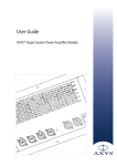
User Guide
AXYS® UniAmp Power Amplifier Module
Model 700
User Guide - AXYS® UniAmp Power Amplifier Module , Model 700
REFERENCE TO EC STATEMENT OF CONFORMITY
This document confirms that products manufactured by
Duran Audio bearing the CE label meet all the requirements
in the EMC directive 2004/108/EC and LV directive
2206/95/EC laid down by the Member States Council for
adjustment of legal requirements. Furthermore the products
comply with the rules and regulations from 30 August 1995
USER’S NOTICE AND DISCLAIMER:
No part of this manual including the software described in
it may be reproduced, transmitted, transcribed, stored in a
database system or translated without the express written
permission of Duran Audio BV.
referring to the electromagnetic compatibility of devices.
Documentation kept by the end user for back-up purposes
Duran Audio products bearing the CE label comply with the
is excluded from the above.
following harmonised or national standards:
All products and corporate names mentioned in this manual
EMC:
may be registered trademarks or copyrights of their
EN 55103-1 :1997
respective companies. They are used here for indicative
EN 55103-2 :1997
purposes only.
Safety:
The information contained in this manual has been carefully
IEC 60065 :2002
checked for accuracy; however no guarantee is given with
Mains Harmonics:
EN 61000-3-2 :2001
Insulation:
Class1
respect to its correctness. Duran Audio BV accepts no
responsibility or liability for any errors or inaccuracies that
may appear in this manual or the products and software
described in it.
Specifications and information contained in this manual are
subject to change at any time without notice.
Duran Audio BV
© 2009 Duran Audio BV. All rights reserved.
Koxkampseweg 10
5301 KK Zaltbommel
The Netherlands
Tel: +31 418 515583
Fax: +31 418 518077
Zaltbommel, February 2009.
2
200905/UAUG_v1.0
User Guide - AXYS® UniAmp Power Amplifier Module , Model 700
TABLE OF CONTENTS
Reference to Statements of Conformity . . . . . . . . . . . . . . . . . . . 2
User’s Notice and disclaimer . . . . . . . . . . . . . . . . . . . . . . . . . . . 2
1. Important Safety Instructions . . . . . . . . . . . . . . . . . . . . . . . . . 4
2. Introduction. . . . . . . . . . . . . . . . . . . . . . . . . . . . . . . . . . . . . . . 5
Applicable models and variants . . . . . . . . . . . . . . . . . . . . 5
3. Connector and wiring details . . . . . . . . . . . . . . . . . . . . . . . . . 6
Connector panel diagram . . . . . . . . . . . . . . . . . . . . . . . . . 6
AC Mains . . . . . . . . . . . . . . . . . . . . . . . . . . . . . . . . . . . . . 6
Audio connections . . . . . . . . . . . . . . . . . . . . . . . . . . . . . . 7
Network connections . . . . . . . . . . . . . . . . . . . . . . . . . . . . 8
4. Presets . . . . . . . . . . . . . . . . . . . . . . . . . . . . . . . . . . . . . . . . . . . 8
Recalling Presets . . . . . . . . . . . . . . . . . . . . . . . . . . . . . . . 8
5. Reset . . . . . . . . . . . . . . . . . . . . . . . . . . . . . . . . . . . . . . . . . . . . 9
6. Other . . . . . . . . . . . . . . . . . . . . . . . . . . . . . . . . . . . . . . . . . . . . 9
Status LED . . . . . . . . . . . . . . . . . . . . . . . . . . . . . . . . . . . . 9
Circuit breaker . . . . . . . . . . . . . . . . . . . . . . . . . . . . . . . . . 9
Cooling. . . . . . . . . . . . . . . . . . . . . . . . . . . . . . . . . . . . . . . 9
7. Configuring with WinControl . . . . . . . . . . . . . . . . . . . . . . . . 10
Connecting to a PC. . . . . . . . . . . . . . . . . . . . . . . . . . . . . 10
Basic software options . . . . . . . . . . . . . . . . . . . . . . . . . . 10
8. Appendix . . . . . . . . . . . . . . . . . . . . . . . . . . . . . . . . . . . . . . . . 11
Network cables. . . . . . . . . . . . . . . . . . . . . . . . . . . . . . . . 11
Specifications . . . . . . . . . . . . . . . . . . . . . . . . . . . . . . . . . 11
200905/UAUG_v1.0
3
User Guide - AXYS® UniAmp Power Amplifier Module , Model 700
1. IMPORTANT SAFETY INSTRUCTIONS
This symbol is intended to alert you to the
12) Use only with the cart, stand, tripod, bracket or
presence of uninsulated dangerous voltages
table specified by the manufacturer, or sold with the
within the product's enclosure that may be of
apparatus. When a cart is used, use caution when moving
sufficient magnitude to constitute a risk of
the cart/apparatus combination to avoid injury from tip-over.
electric shock.
13) Unplug this apparatus during lightning storms or when
unused for long periods of time.
This symbol is used throughout this manual and
14) Refer servicing to qualified service personnel. Servicing
is intended to alert you to the presence of
is required when the apparatus has been damaged in any
important instructions.
way, such as power-supply cord or plug is damaged, liquid
has been spilled or objects have fallen into the apparatus,
the apparatus has been exposed to rain or moisture, does
1) Read these instructions.
not operate normally, or has been dropped.
2) Keep these instructions.
3) Heed all warnings.
Warning -To reduce the risk of fire or electric
4) Follow all instructions.
shock, do not expose this apparatus to rain
5) Do not use this apparatus near water.
6) Clean only with dry cloth.
or moisture.
Warning - To disconnect this apparatus from the mains
power supply, turn off the power at the switch labelled
7) Do not block any ventilation openings. Install in
Circuit breaker on the connector panel and remove the
accordance with the manufacturer's instructions.
connector from the mains input socket labelled Mains
8) Do not install near any heat sources such as radiators,
Power Input.
heat registers, stoves, or other apparatus (including
Warning - Do not expose the internal backup battery to
amplifiers) that produce heat.
excessive heat such as sunshine, fire or the like. Note that
9) Do not defeat the safety purpose of the polarised or
this battery is not user-replaceable.
grounding-type plug. A grounding-type plug has two blades
and a third grounding prong. The wide blade or the third
prong are provided for your safety. If the provided plug does
not fit into your outlet, consult an electrician for
replacement of the obsolete outlet.
10) Protect the power cord from being walked on or
pinched particularly at plugs, convenience receptacles, and
the point where they exit from the apparatus.
11) Only use attachments/accessories specified by the
manufacturer.
4
200905/UAUG_v1.0
User Guide - AXYS® UniAmp Power Amplifier Module , Model 700
2. INTRODUCTION
This guide describes the operating procedures for the
APPLICABLE MODELS AND VARIANTS
®
AXYS UniAmp 700 power amplifier module.
The UniAmp 700 is the power amplifier module fitted as
The UniAmp 700 is a mains-powered power amplifier
standard to the following AXYS® powered loudspeakers:
module incorporating a DSP (Digital Signal Processing)
section. It has a single input and multiple speaker outputs,
the number being model-dependent. The DSP section acts
Target range:
as a multi-band crossover and also controls beamforming
U-16
and beamshaping, per-channel levels, delays, limiting
action, etc.
The DSP may be configured to suit individual applications
and requirements via AXYS®’s WinControl software
application. This level of configuration should not be
confused
with
the
per-model
factory
hardware
ScopeG2 range:
T-2112
T-2115
UB-25
SourceG2 range
configuration referred to in the next section (Applicable
T-07
models and variants). WinControl also permits constant
B-07*
monitoring of all units in a multiple-cabinet system during
operation. WinControl is available as download from
IMPORTANT –Each UniAmp 700 is configured
http://www.duran-audio.com/software/WinControl.html.
in the factory to suit the loudspeaker type in
This guide does not cover any aspects of the host
which it is to be installed. These configuration differences
loudspeaker system or installation thereof; these topics are
are at hardware level and are significant, and it is NOT
the subject of a separate Installation Manual, supplied with
possible to interchange UniAmp 700 modules between
each loudspeaker.
loudspeaker types.
The UniAmp 700 has no user-serviceable parts, and no
attempt should be made to remove a module from its host
enclosure. Please contact your AXYS® distributor in the
event of faulty operation.
*Note that model B-07 can also be used as part of a ScopeG2 configuration.
200905/UAUG_v1.0
5
User Guide - AXYS® UniAmp Power Amplifier Module , Model 700
3. CONNECTOR AND WIRING DETAILS
CONNECTOR PANEL DIAGRAM
8
1
2
3
4
9
5
1 Audio input connector
2 Audio link connector
3 RS-485 network input connector
4 RS-485 network link connector
5 AC mains input connector
6 AC mains link connector
7 Mains switch/resettable circuit breaker
8 Status LED
9 Reset and Preset Control (access hole)
AC MAINS
Two Neutrik® PowerCon® chassis connectors are
fitted to the UniAmp 700. The Input connector
(coloured blue) is a Neutrik® Type A, and is intended
for connection of the AC mains supply; the Link
connector (coloured grey) is a Neutrik® Type B, and is
to facilitate connection to another module in an
adjacent enclosure.
Note that the Link connector is not
independently fused.
6
6
7
The full-load power consumption of the amplifier
module is 700 VA under typical normal operating
conditions. When “daisy-chaining” AC mains between
several enclosures of the same type using the Input
and Link connectors, ensure that the current capacity
of the supply is sufficient for ALL amplifiers in
the chain, and additionally, that the total current
drawn by all the amplifiers does not exceed 20 A
(the maximum rated current of the PowerCon®
connectors).
In practice, this means that the maximum
number of amplifiers (including the first
one) that may be daisy-chained in this way is six (230
V operation) or three (115 V operation).
Only wire AC mains connectors according to the table
below:
PIN
CONNECT
COLOUR
(Europe)
COLOR
(US)
L
Live
Brown
Black
N
Neutral
Blue
White
Earth
(Ground)
Geen/Yellow
Green
200905/UAUG_v1.0
User Guide - AXYS® UniAmp Power Amplifier Module , Model 700
The PowerCon® connectors are plugged and
unplugged as shown in the diagram below.
Engagement
The UniAmp 700’s audio input and output are twin
transformer-balanced, and are designed to operate at
a nominal level of 0 dBV. Balanced system
interconnection, using twin-and-screen microphone
cables is strongly recommended.
Wire the audio connectors as follows:
2.
1.
Separation
PIN
CONNECT
COLOUR
1
Screen
Cable Screen
2
Hot (+)
Red*
3
Cold (-)
Black*
1.
2.
3.
* Typical colours, may vary with cable make and type.
IMPORTANT – The PowerCon® connectors
should never be plugged or unplugged
when there is power on the connectors, regardless of
whether the amplifier is switched on or not. ALWAYS
ensure that the mains supply is turned off before
inserting or removing either PowerCon®.
1
3
AUDIO CONNECTIONS
2
1
2
3
Two latching 3-pin XLR connectors are fitted for audio
interconnections. The Input connector (female) is for
connection of an audio input signal; the Link
connector (male) is hardwired to the input connector,
and facilitates easy connection to another amplifier
in an adjacent enclosure.
200905/UAUG_v1.0
7
User Guide - AXYS® UniAmp Power Amplifier Module , Model 700
4. PRESETS
NETWORK CONNECTIONS
Two latching 5-pin XLR connectors are fitted for RS-485
network interconnections. A PC running WinControl may be
connected, via an appropriate interface (either RS-232 to
RS-485 or USB to RS-485) to the Input connector, if control
The UniAmp 700’s DSP section includes 8 Presets;
memory locations in which sets of configuration
parameters can be stored. These permit the
loudspeaker cabinet to be “fine-tuned” to suit
different types of programme material and venue.
WinControl-supported device (e.g. an adjacent enclosure).
When a settings file is loaded into the unit from a PC,
the user can specify in WinControl which Preset
memory it will be loaded into.
The network connectors should be wired as follows:
RECALLING PRESETS
and monitoring during operation are required. The Link
connector (male) is to facilitate easy connection to another
PIN #
Function
1
Screen
2
Data Tx +
3
Data Tx -
4
Data Rx -
5
Data Rx +
1
5
2
4
3
2
1
3
4
5
See page 11 for information regarding suitable network
cable types. See Section 7 (Configuring with WinControl)
for more information about network operation and
software options.
The simplest method of recalling a previously-saved
Preset is via WinControl. This necessitates a network
connection to the loudspeaker system. Refer to the
WinControl Help files for further information.
If a network connection is not in place, or a PC with
WinControl is unavailable, Presets may be recalled
manually using the Reset & Preset Control button*.
This button is hidden behind a small access hole on
the amplifier module’s conector panel, and can be
accessed with an implement such as a fine jewellers’
screwdriver or a straightened-out paper clip.
A single short press (< 1 sec) on this button will
increment the current Preset number, i.e. if the system
is currently running Preset 2, pressing the button will
load Preset 3. While the button is pressed, the Status
LED will change colour from green to red. Loading of
the next Preset is confirmed by the LED flashing the
appropriate number of times, i.e., it will flash 3 times
when Preset 3 is loaded. Using this method, repeated
button presses will load each Preset in turn.
Note that the amplifier module always
powers-up with the last-used Preset active.
Note also that a long (> 1 sec) button press
has a different function (see following page).
*Please note that this feature may not be available on Target U-16 enclosures with early serial numbers. Please contact your
AXYS® dealer for more information.
8
200905/UAUG_v1.0
User Guide - AXYS® UniAmp Power Amplifier Module , Model 700
5. RESET
One of the eight Preset memories acts as a “default”
memory, referred to as the “preferential preset” by
WinControl. Users are recommended to store a known
base configuration in this Preset, and to protect it via
WinControl. This Preset may be reloaded by a long (>
1 sec) press on the Reset & Preset Control button (but
see note on previous page regarding early U-16 serial
numbers).
Resetting the UniAmp 700 may also be carried out via
WinControl; see the WinControl Help files for more
information.
CIRCUIT BREAKER
The amplifier module’s mains on/off switch is also a
resettable 6.3 A circuit breaker. If the module draws
current in excess of the rating from the AC mains (as
may happen in a fault condition), the circuit breaker
will trip, disconnecting the power. The fault condition
should be identified and rectified before attempting
to reset the breaker. Note that under extreme fault
conditions, it may not be possible to reset the breaker.
There are no user-replaceable fuses within the Target
System amplifier module.
6. OTHER
COOLING
STATUS LED
The bi-colour Status LED has several functions:
1. To indicate that power is being applied to the unit,
the LED shows green for normal operation.
2. To indicate a fault state. The conditions for a fault
state are defined as part of the WinControl settings
file. If the conditions are met, the LED illuminates
red and an error indication is also communicated
via WinControl.
Loudspeaker enclosures equipped with the UniAmp
700 include fan-assisted cooling of the electronic
assembly. The direction of airflow is from intakes at
the front of the enclosure, with exhaust through slots
in the connector panel. The fan is automatic and is
controlled via a “whisper algorithm” via the DSP
section, which adjusts the fan speed according to
temperature and input signal level. Care should be
taken in installation not to restrict the airflow.
3. To confirm which Preset is being loaded (see
Recalling Presets, Section 4).
4. Unit identification: if the LED is set (in software) to
duplicate the functions of the LED on the front of
the enclosure, it will also confirm unit identity when
requested by WinControl.
200905/UAUG_v1.0
9
User Guide - AXYS® UniAmp Power Amplifier Module , Model 700
7. CONFIGURING WITH WINCONTROL
Correct operation of a UniAmp 700 module may be
confirmed using WinControl software.
A full description of WinControl is beyond the scope of
this manual and further information is available in the
application’s Help files. Instructions on how to install
WinControl on a PC are included with the Program
Set. Instructions on the use of the AXYS® RS-485
interface are included with the interface itself.
CONNECTING TO A PC
The PC connects to the amplifier module via an RS485 interface adapter. (Two versions of adapter are
available from Duran Audio, for connecting to PCs
either via a USB or an RS-232 port). Use either a 5pin XLR female to 5-pin XLR male cable or a 9-pin
Dsub to 5-pin XLR male. These cables (5 m in length)
are supplied with the WinControl Program Set, the
type depends on the RS-485 interface type. The RS485 interface should then be connected to either the
PC’s 9-pin COM port (in the case of a RS-232 to RS485 interface) or a USB port (in the case of a USB to
RS-485 interface).
The particular set of parameters which can be
adjusted via WinControl varies with loudspeaker
model. Typically, it includes delay, gain and multi-band
parametric EQ.
In addition to the parameters determining the audio
performance, the various Preset memories may have
alternative configurations stored in them, and recalled
as required. Unit monitoring may also be configured,
with the conditions for a fault state to be signalled
being registered. Additionally, multiple loudspeaker
units may be ‘grouped’ together in software, allowing
very rapid adjustment of the overall loudspeaker array
performance.
Full details of the options available within WinControl
are available in the application’s Help files.
BASIC SOFTWARE OPTIONS
WinControl allows the various parameters of the
UniAmp’s DSP section to be set according to the
installer’s wishes. This enables the performance of the
loudspeaker enclosure to be accurately optimised to
suit both the venue and the type of programme
material being handled (speech, rock, opera, etc.) In
the case of the Target U-16 enclosure, AXYS® DDA
(Digital Directivity Analysis) may be employed to
model the room’s acoustics accurately, and the results
of this analysis then used to optimise the array’s
performance.
10
200905/UAUG_v1.0
User Guide - AXYS® UniAmp Power Amplifier Module , Model 700
8. APPENDIX
NETWORK CABLES
The type of cable necessary for correct operation of
the RS-485 network is twin twisted pair with each pair
individually shielded. Numerous cables of this type are
readily available and cables broadly meeting the
specifications given below (which are those of a
common commercially-available cable) are likely to be
suitable.
PARAMETER
VALUE
Characteristic impedance
100 ohms
Capacitance (core to core)
41 pF/m
Capacitance (core to screen)
72.5 pF/m
DC resistance (core)
78.7 ohms/km
DC resistance (screen)
59.1 ohms/km
Additional information regarding network
connections and grounding strategies may be
obtained at :
http://www.duran-audio.com/pdfs/
downloads/papers/grounding_strategy.pdf
SPECIFICATIONS
Please refer to the download section of our website
for product specifications.
200905/UAUG_v1.0
11
IS A REGISTERED TRADE MARK OF
DURAN AUDIO BV
Koxkampseweg 10, 5301 KK Zaltbommel, The Netherlands.
tel. +31 418 515583 fax. +31 418 518077
http://www.duran-audio.com [email protected]