1
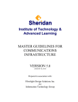
Installation and
Operation Guide
KMD–5559
CommTalk
Contents
Description ............................................................................................................................3
Models ....................................................................................................................................3
Specifications .........................................................................................................................3
Accessories ............................................................................................................................4
Mounting ...............................................................................................................................5
Connecting the KMD–5559 .................................................................................................5
Connecting power ................................................................................................................9
Operation ...............................................................................................................................9
Using the KMD–5559 with HCM .......................................................................................9
Connecting to a remote system ........................................................................................10
Tier 1 networks ...................................................................................................................10
Using the CommTalk with NetView ...............................................................................10
Configuring for alarms ......................................................................................................11
Alarm handling ...................................................................................................................11
Programming alarms .........................................................................................................13
Revision E
906-019-01E
KMC Controls
Important notices
NetView, WinControl and the KMC logo are a registered trademarks of KMC
Controls, Inc.
©2005, KMC Controls, Inc.
All rights reserved. No part of this publication may be reproduced, transmitted,
transcribed, stored in a retrieval system, or translated into any language in any
form by any means without the written permission of KMC Contols, Inc.
Printed in U.S.A.
Disclaimer
The material in this manual is for information purposes only. The contents and
the product it describes are subject to change without notice. KMC Controls, Inc.
makes no representations or warranties with respect to this manual. In no event
shall KMC Controls, Inc. be liable for any damages, direct or incidental, arising
out of or related to the use of this manual.
KMC Controls
P.O. Box 497
19476 Industrial Drive
New Paris, IN 46553
U.S.A.
TEL: 1-574-831-5250
FAX: 1-574-831-5252
E-mail: [email protected]
Kreuter Marketing Canada Inc.
38 Buttermill Ave., Unit B
Concord, Ontario L4K-3X3
Canada
Tel: 905-738-8588
Fax: 905-738-8587
E-mail: [email protected]
KMC Sudamericana
Lorenzo Carnelli 1218
C.P. 11200 Montevideo
South America
Tel: 598-2412-3913
Fax: 598-2412-2514
E-mail: [email protected]
KMC Beijing Representative Office
Room 8C, 8th Fl., Bldg., Fuhua Mansion
No. 8, Chaoyangmen North Avenue
Dongcheng District,
Beijing, China 100027
TEL: 86-10-6554-2003
FAX: 86-10-6554-2004
E-mail: [email protected]
2
Revision E
KMD–5559 CommTalk Interface Module
Description
Description
The KMD-5559 CommTalk is a microprocessor-based, programmable,
communications interface module. Used in conjunction with a KMD–5569
external modem, the CommTalk manages communications between the KMC
Tier-2 controller network and external services. Connect the CommTalk to a
stand-alone Tier 2 network to:
◆
◆
◆
◆
Store and forward alarms to a computer operating WinControl.
Send text and numeric pager messages.
Manage and monitor a Tier 2 network from a remote computer with a
modem and WinControl.
Connect a computer running WinControl to a Tier 2 network.
Models
Table 1 KMD–5559 models and features
Modem or PC
connection speed
Tier 2 network speed
Supplied with HPO-0068
plug-in transformer for 120
volt AC mains.
19.2 kilobaud
Auto (9.6-38.4 kilobaud)
KMD-5559-2
Supplied with HPO-0068
plug-in transformer for 120
volt AC mains.
9.6 kilobaud
Auto (9.6-38.4 kilobaud)
KMD-5559-E
Not supplied. Use Stancor
transformer STAF-2098F or
equivalent for 240 volt AC
mains.
19.2 kilobaud
Auto (9.6-38.4 kilobaud)
KMD-5559-2E
Not supplied. Use Stancor
transformer STAF-2098F or
equivalent for 240 volt AC
mains.
9.6 kilobaud
Auto (9.6-38.4 kilobaud)
Model
Transformer
KMD–5559
Specifications
Revision E
Alarm buffering
Up to 64 action alarms
Up to 128 non-action alarms
Pager compatibility
Supports text and numeric paging through
WinControl programming.
Supply Voltage
9 to 24 volts AC or DC
Connects with 2.1 x 5.5 mm barrel plug.
Weight
8.7 oz. (247 grams)
Environmental limits
Operating
Shipping
Humidity
32 to 120°F (0 to 49°C)
–40 to 140°F (–40 to 60°C)
0–95% RH, non-condensing
3
Accessories
KMC Controls
Memory back-up
CommTalk maintains the volatile memory for a
minimum of 24 hours to retain the buffered
messages from the KMC digital controllers in
event of a power failure.
Regulatory
UL 916 Energy Management Equipment
CE Mark
Dimensions
Table 2 KMD–5559 dimensions
A
B
C
D
Height (not shown)
5.38 in.
3.38 in.
4.0 in.
3.0 in.
1.32 in.
137 mm
86 mm
102 mm 76 mm
34 mm
A
B
D
C
Illustration 1 KMD–5559 dimensions
Accessories
HPO-0068
KMD-5614
KMD–5615
KMD-5625-1
KMD-5628-1
KMD-5569
4
Power Supply
4–wire flat cable with male RJ–12 connectors for
CommTalk to KMD Digital Controller
6–wire flat cable with male RJ–12 connectors for
CommTalk to modem or computer
RJ–12 female to 25–pin D-shell modem adapter.
RJ–12 female to 9–pin D-shell PC adapter.
56K baud external modem
Revision E
KMD–5559 CommTalk Interface Module
Mounting
Connecting the
KMD–5559
Mounting
Use the four mounting holes to securely mount the controller using #6 hardware
inside a UL-approved Enclosed Energy Management Equipment Panel or other
suitable protective enclosure. Refer to KMD–5559 dimensions on page 4 for
mounting hole location and spacing.
The KMD–5559 connects between the RS–232 serial port on a computer or modem
and a KMC digital Tier 2 network. See Illustration 4 for connection details.
Power connector
Status LED
Computer/
Modem
connector
Tier 2 (sublan)
connector
Illustration 2 KMD–5559 Components and connections
Connecting to a Tier 2 network
The KMD–5559 connects directly to Tier 2 controllers with a 4-wire, RJ–12 cable.
Refer to Illustration 4 for connection details. To connect to a Tier 2 controller:
1. Connect one RJ–12 connector on a KMD–5614 cable to the Tier 2 (Sublan)
connector on the CommTalk module.
2. Connect the other RJ-12 connector on the KMD–5614 cable to a Tier 2
controller. Do not connect other devices to the same port as the CommTalk
module.
3. Set the EOL jumpers on the Tier 2 controller if required:
◆ If you connect to a stand-alone, single controller installation the controller
end of line (EOL) switches must be set to the ON position.
◆ If the module is installed in a larger network, the EOL switches on the
controller must be ON if the device is the last device in the segment, or OFF
if it is not. Refer to the installation guide for the appropriate controller.
Detail
During power up, the CommTalk automatically discovers the Tier 2 network
configuration including the speed of the network. If any of the following
parameters change, cycle the KMD–5559 power to reestablish communication.
◆ When network baud changes
◆ When the CommTalk is connected to a different controller
◆ If controllers are added to the network.
◆ When changing between a computer or modem.
Revision E
5
Connecting the KMD–5559
KMC Controls
Connecting a modem
Note
KMC Controls recommends using a US Robotics, 33.6 to 56K external modem
with the CommTalk. KMC Controls supplies this modem as model number
KMD-5569.
Connect to an approved modem with a KMD-5615 interface cable and an
appropriate adaptor. See Illustration 4 for modem connection details
1. Connect one end of the interface cable to the PC/Modem connector on the
KMD–5559.
2. Connect the other end of the cable to a KMD-5625-1 25-pin modem adaptor
and connect the adaptor to the modem.
3. Configure the modem as described in Configuring to use a modem on page 7.
Use the settings in the Remote Modem column.
Detail
To maintain high quality communications, a data grade telephone line is
highly recommended.
6
Revision E
KMD–5559 CommTalk Interface Module
Connecting the KMD–5559
Configuring to use a modem
The CommTalk Module is designed to operate with a specific modem
configuration. The following material applies to the recommended US Robotics
modem.
The host modem (PC end) and remote modem (Tier 2) must have the dip switches
at the rear of the modem configured as shown in Table 3 for reliable
communications. Illustration 3 shows the dip switch arrangement for a
KMD–5569 US Robotics external modem.
Table 3 KMD–5569 modem switch settings
Switch
Remote Modem Host Modem
Number (Tier 2)
(PC)
Function*
1
UP
UP
Data Terminal Ready (DTR) Override
2
UP
UP
Verbal Numeric Result Codes
3
DOWN
DOWN
Result Code Display
4
DOWN
DOWN
Command Local Echo Suppression
5
UP
UP
Auto Answer Suppression
6
UP
UP
Carrier Detect (CD) Override
7
UP
UP
Power-0n and ATZ Reset Software Defaults
8
DOWN
DOWN
AT Command Set Recognition
*
Refer to the instructions supplied with the modem for additional details about
switch function.
Off
On
Illustration 3 KMD–5569 modem configuration switches
Revision E
7
Connecting the KMD–5559
KMC Controls
Connecting to a PC
1. Connect one end of the KMD-5615 interface cable to the module.
2. Connect the other end to a 9-pin adaptor and connect this to a serial port on
the PC.
3. Configure the CommTalk with WinControl XL. See Configuring for alarms on
page 11.
KMD–5625-1
KMD–5615 cable
Configure for
Action alarms
(Dial-out alarms)
Configured for Nonaction alarms
KMD–5628-1
NETWORK
G
B
A
COMM
Analog
GROUNDS
1
R E A DY
4
5
8
SW.
7 COM. 6
5
8
8
SW.
5
INPUTS
6
7
4
5
INPUTS
6
7
4
5
INPUTS
6
7
4
7 COM. 6
3
3
3
5
SW.
SW.
4
4
2
2
2
7 COM. 6
3 COM. 2
NETWORK
G
B
A
COMM
Analog
GROUNDS
1
3 COM. 2
R E A DY
Analog
GROUNDS
COMM
R E A DY
1
SW.
ON
OFF
1 AMP
1
GROUNDS
ON
OFF
1 AMP
1
GROUNDS
ON
OFF
1 AMP
1
GROUNDS
3 COM. 2
AB
EOL
POWER
AB
EOL
POWER
AB
EOL
POWER
SW.
PC PORT
PC PORT
PC PORT
NETWORK
G
B
A
KMD–5614
8
8
8
Tier 2
Illustration 4 Typical Tier 2 arrangement
8
Revision E
KMD–5559 CommTalk Interface Module
Connecting power
Connecting power
The KMD–5559 does not include a power switch. The module is powered when
power is connected.
◆
◆
◆
Before connecting power, verify that all connections are complete and
correct.
If a modem is connected, turn the modem on before powering the
CommTalk.
Connect the barrel connector from the power supply cable to the connector
on the module, then plug in the power supply to the correct AC mains.
HPO–0068
Power supply
(120 volt AC mains)
Illustration 5 KMD–5559 power supply connection
Operation
When power is applied to the CommTalk, the following initialization process
takes place:
◆
◆
◆
◆
Using the
KMD–5559 with
HCM
When using the KMD–5559 as the interface device for connections with Hardware
Configuration Manager (HCM), cycle the power after the following actions.
◆
◆
Revision E
The status LED illuminates and remains illuminated while the CommTalk
performs an internal initialization.
When initialization is complete, the CommTalk emits two audible beeps.
This process may take up to one minute depending on the number of
controllers on the Tier 2 network to which the KMD–5559 is connected.
The status LED will turn off while the CommTalk configures the modem.
This will normally take less than one minute.
When completely initialized, the status LED will flash once every second.
After changing network baud
When changing controllers
9
Connecting to a remote system
Connecting to a
remote system
KMC Controls
To connect to a remote Tier 2 network with a dial-up modem, use a KMD–5569
modem.
1. Connect the modem following the directions supplied with the modem and
computer.
2. Set the switches on the back of the KMD–5569 modem to the positions in the
Host Modem column of Table 3.
3. Choose CommTalk from the System column in the WinControl System List
dialog box.
Local
connection
for non-action
alarms
Modem
connection
for action
alarms
Illustration 6 System list in WinControl
Tier 1 networks
Using the CommTalk
with NetView
10
KMC Controls designed the CommTalk for stand-alone Tier 2 networks. For
Tier 2 networks connected to a Tier 1 controller, use the modem connectivity
designed into the Tier 1 controllers. If a CommTalk is used for any reason on a
mixed network, disable CommTalk alarms with WinControl to prevent
unpredictable alarm operation.
If a KMD–1001 or KMD–1002 NetView is connected to the same Tier 2 network as
a CommTalk, enable only the NetView or CommTalk to acknowledge alarms.
Enabling both devices to acknowledge alarms will result in unpredictable alarm
operation.
Revision E
KMD–5559 CommTalk Interface Module
Configuring for
alarms
Configuring for alarms
Before operating the KMD-5559 CommTalk Module, use WinControl to set the
Alarm Acknowledgements in the About CommTalk dialog box. Refer to the
WinControl XL User’s Manual for additional information.
◆
◆
Action alarms—Alarms that are programmed into a controller to dial,
through a modem, a computer running WinControl or a text or numeric
pager service.
Non-action alarms—Alarms that are sent only to a computer running
WinControl. The computer is directly connected to a Tier 2 network through
a CommTalk. Operators can also retrieve non-action alarms by establishing a
modem connection between a computer and Tier 2 network with a modem
and CommTalk.
Illustration 7 Comm Talk dialog box
Caution
If a CommTalk is not powered for more than 24 hours, both the
Ack. Non_Action Alarms and Ack. Action Alarm check boxes may uncheck.
Alarm handling
The CommTalk manages the process of dialing pre programed telephone
numbers and sending action alarm messages to services that display the alarms.
The display service can be a:
◆
◆
◆
a computer running WinControl
a commercial numeric
a commercialtext pager service.
Telephone numbers, personal identification numbers (PINs), messages and alarm
conditions are programmed into individual Tier 2 controllers with Control Basic
and WinControl. See the next section, Programming alarms, for programming
examples of each type of service.
Auto dialing for action alarms
When CommTalk receives an action alarm from a controller, it
immediately—through the attached modem—dials the telephone number of the
service. When the CommTalk connects to the service, it then delivers the message
Revision E
11
Alarm handling
KMC Controls
to the service. For text pager and WinControl services, if the CommTalk connects
to a service but does not receive an acknowledgement from the service, it will
then attempt to reconnect to the service three more times at three-minute
intervals. For numeric pager service, there is no acknowledgment process and the
message is considered delivered upon connection. New alarms are not handled
and remain in the originating controller while the CommTalk is delivering an
alarm to a service.
Undeliverable alarms
If connection with a service is not successful, the message remains in the buffer
until an operator retrieves the alarms with WinControl. To indicate an alarm was
undeliverable, CommTalk overwrites the first five characters of the message with
*U/D* which is viewable in WinControl. CommTalk will save up to 64 messages
and when the buffer is full, no other messages can be saved. CommTalk attempts
to deliver the last message indefinitely until successful connection to a computer
or pager service.
Incoming calls
The CommTalk, when connected to a modem and not attempting a call to service,
sets the modem to auto-answer mode. When an incoming connection is
established with WinControl, the CommTalk does not send action alarms to
WinControl.
12
Revision E
KMD–5559 CommTalk Interface Module
Programming alarms
Programming alarms
Use Control Basic to program the telephone number, pager PIN (personal
identification number) and messages into a controller that is connected to the
same Tier 2 network as the Comm Talk. The following sections describe examples
and the format for both text and numeric pagers.
Numeric pager
Use the following format to program a numeric pager action alarm.
Format:
10 DALARM expression , 2 , NPAGE( telephone_number,,,,, ) numeric_message
The field telephone_number cannot include punctuation that is not shown in the
example. Each comma (,) in telephone_number produces a two-second delay.
Example:
10 DALARM IN1 , 2 , NPAGE( 18005551432,,,,, ) 5555555
When sending alarms to a pager service, the Comm Talk adds the prefix 001 to
active alarms and the number 000 to restored alarms. To surpress the prefixes, add
the character N after the pager number.
Example:
10 DALARM IN1 , 2 , NPAGE( 18005551432N,,,,, ) 5555555
Text pager
Use the following format to program a text pager action alarm.
Format:
10 DALARM IN1 , 1 , TPAGE( telephone_number-PIN ) message
The field telephone_number cannot include punctuation that is not shown in the
example. Each comma (,) in telephone_number produces a two-second delay. To
add a PIN, separate it from telephone_number with a hyphen (-). In following
example, the number 1234567 is the pager PIN (personal identification number)
and Intrusion is the text message.
Example:
10 DALARM IN1 , 1 , TPAGE( 18005551234-1234567 ) Intrusion
The default speed that CommTalk sends messages to a pager service is 1200 baud.
To change speed, add a < for 2400 or > for 9600 baud. The following example
sends messages to a text pager at 2400 baud.
Example:
10 DALARM IN1 , 1 , TPAGE<( 18005551234-1234567 ) Intrusion
When sending alarms to a pager service, the Comm Talk normally appends res to
reset alarm messages. To suppress the prefixes, add the character N after the
pager number.
Example:
Revision E
10 DALARM IN1 , 1 , TPAGE<( 18005551234-1234567N ) Intrusion
13
Programming alarms
KMC Controls
Modem dial-out to computer
Upon the reciept of an action alarm, the CommTalk establishes a modem
connection to a computer running WinControl. When a connection is made,
CommTalk sends the current action alarms and then terminates the call.
Example:
20 ALARM IN2 > 80 , 3 , CALL( 18005554321 ) Temp too high
“Temp too high” is the text delivered.
Note
WinControl can receive action alarms from a CommTalk only if it is in standby
mode. If WinControl is connected to any controller system, it will not process
an action alarm from a CommTalk.
14
Revision E