1
1.
Getting Started
1.1
Features
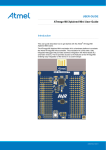
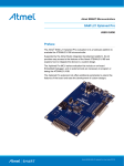
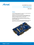
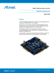
The ATSAMD10 Xplained Mini evaluation board provides a development platform for the Atmel ATSAMD10.
1.2
Design Documentation and Related Links
The most relevant documents and software for the evaluation board is available here:
http://www.atmel.com/tools/SAMD10-XMINI.aspx
1.3
Board Assembly
The Xplained Mini board is very flexible and can be used in a number of ways. E.g. as your own prototype for
SW development and HW verification.
1.3.1
In Customer Development Assembly
The ATSAMD10 Xplained Mini board can be wired into the customer prototype assembly by using the on-board
connector grid, where the target signals are available.
1.3.2
Connecting an Arduino Shield
®
By assembling receptacles in the marked positions (J200, J201, J202, and J203) Arduino shields can be
mounted.
1.3.3
Standalone Node
The ATSAMD10 Xplained Mini board can be used as a standalone node - use the 4xAAA or 2xAAA battery
pack available in Atmel store to provide power.
1.4
Connecting the Kit
How to connect the evaluation board.
1.4.1
Connect the Kit to Atmel Studio
How to connect the ATSAMD10 Xplained Mini board to Atmel Studio.
1.4.2
1
1.
Download and install Atmel Studio version 6.2 or later.
2.
Launch Atmel Studio.
3.
Connect the board to the USB port and it will be visible in Atmel Studio.
Connect the Target UART to the mEBDG COM Port
All Xplained Mini boards have an embedded debugger (mEBDG) with a number of features, among them a
CDC/COM port which enables the user to connect the ATSAMD10 UART to the PC.
1.5
1.
Connect the mEDBG USB to the PC.
2.
Use the Device Manager to find the COM port number.
3.
Default COM port settings are 9600baud N81. The COM port settings can be changed using the Device
Manager.
Programming and Debugging
How to program and debug the Xplained Mini board.
1
http://www.atmel.com/tools/atmelstudio.aspx
ATSAMD10 Xplained Mini User Guide [USER GUIDE]
42387A-MCU-01/2015
3