1
USER GUIDE
Atmel ATSAMR21ZLL-EK
Preface
®
The Atmel ATSAMR21ZLL-EK evaluation kit is a hardware platform based on
Atmel ATSAMR21G18A microcontroller. The kit is fully integrated with the Atmel
®
Studio development platform, enabling application development with BitCloud
®
ZigBee PRO libraries.
The kit supports on-board embedded debugger, antenna diversity, RGB LED,
QMatrix™ interface, OLED display, joystick, user LEDs, user switches, Atmel
Xplained Pro extension header, external USB, and UART interfaces.
42462A-MCU-06/2015
Table of Contents
Preface .......................................................................................... 1
1. Introduction .............................................................................. 3
1.1.
1.2.
Features .............................................................................. 3
Kit Overview ......................................................................... 4
2. Getting Started ........................................................................ 5
2.1.
2.2.
2.3.
Quick-start ........................................................................... 5
Connecting the Kit ................................................................. 5
Design Documentation and Related Links .................................. 5
3. Hardware User Guide ............................................................. 6
3.1.
3.2.
3.3.
Power Supply ....................................................................... 6
3.1.1.
Measuring SAM R21 Power Consumption ...................... 6
Connectors .......................................................................... 6
3.2.1.
I/O Extension Headers ............................................... 6
3.2.2.
Other Headers and Connectors ................................... 7
Peripherals ........................................................................... 8
3.3.1.
Crystal .................................................................... 8
3.3.2.
RF Interface ............................................................. 9
3.3.3.
Touch Interface ........................................................ 9
3.3.4.
RGB LED .............................................................. 10
3.3.5.
OLED Display ......................................................... 10
3.3.6.
Joystick ................................................................. 11
3.3.7.
Serial Flash ............................................................ 11
3.3.8.
Temperature Sensor ................................................ 11
3.3.9.
Crypto Authentication ............................................... 11
3.3.10. Serial Communication Interface .................................. 11
3.3.11. Mechanical Buttons .................................................. 12
3.3.12. User LED ............................................................... 13
3.3.13. SAM R21 USB ........................................................ 13
3.3.14. Embedded Debugger Implementation .......................... 13
3.3.15. MAC ID ................................................................. 14
4. Agency Certification .............................................................. 15
4.1.
4.2.
4.3.
4.4.
United States (FCC) .............................................................
European Union (ETSI) ........................................................
Canada (IC) .......................................................................
List of Antennas Tested With This Product ...............................
15
15
16
16
5. Hardware Revision History and Known Issues ..................... 17
5.1.
5.2.
Identifying Product ID and Revision ......................................... 17
Revision 3 .......................................................................... 17
6. Document revision history ..................................................... 18
7. Evaluation Board/Kit Important Notice .................................. 19
Atmel ATSAMR21ZLL-EK [USER GUIDE]
42462A-MCU-06/2015
2
1.
Introduction
1.1
Features
●
Atmel ATSAMR21G18A ARM Cortex -M0+ based on 32-bit microcontroller with best-in-class 2.4GHz RF
transceiver
●
Antenna Diversity
●
®
●
Two ceramic chip antenna (2540AT18A100)
●
Two MS-147 connector for RF test port
Touch Interface
●
Two QMatrix™ button
●
One QMatrix™ Slider
●
RGB LED
●
OLED Display
●
Joystick
●
Serial Flash
●
Temperature sensor
●
CryptoAuthentication™
●
Serial communication header
●
Mechanical button
●
EDBG USB and SAM R21 USB
●
64bit MACID stored in SAM R21 NVM
●
Embedded debugger (EDBG)
●
●
●
®
●
USB interface
●
Programming and debugging on board SAM R21 through Serial Wire Debug (SWD)
●
Virtual COM-port interface to target via UART
Digital I/O
●
Two mechanical buttons (user and reset button)
●
Two user LED
●
One extension header
Four possible power sources
●
External power
●
Embedded debugger USB
●
Target USB
●
Battery Power
32kHz crystal
Atmel ATSAMR21ZLL-EK [USER GUIDE]
42462A-MCU-06/2015
3
1.2
●
16MHz crystal
●
USB interface, device
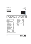
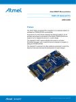
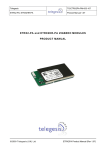
Kit Overview
ATSAMR21ZLL-EK evaluation kit is a hardware platform based on Atmel ATSAMR21G18A microcontroller
featuring wireless, QMatrix™ , RGB LED, external flash, display, etc. With onboard debugger, the kit is fully
integrated with the Atmel Studio development platform, enabling application development with BitCloud ZigBee
PRO libraries.
Figure 1-1. ATSAMR21ZLL-EK Evaluation Kit Overview
Atmel ATSAMR21ZLL-EK [USER GUIDE]
42462A-MCU-06/2015
4
2.
Getting Started
2.1
Quick-start
Three steps to start exploring the Atmel Xplained Pro Platform
2.2
1
●
Download and install Atmel Studio
●
Launch Atmel Studio
●
Connect a Micro-B cable to the DEBUG USB port
Connecting the Kit
When connecting Atmel ATSAMR21ZLL-EK to your computer for the first time, the operating system will do a
®
®
driver software installation. The driver file supports both 32-bit and 64-bit versions of Microsoft Windows XP
and Windows 7.
Once connected the green power LED will be lit and Atmel Studio will autodetect which Xplained Pro
evaluation- and extension kit(s) that's connected. You'll be presented with relevant information like datasheets
and kit documentation. You also have the option to launch Atmel Software Framework (ASF) example
applications. The target device is programmed and debugged by the on-board Embedded Debugger and
2
no external programmer or debugger tool is needed. Refer to the Atmel Studio user guide for information
regarding how to compile and program the kit.
2.3
Design Documentation and Related Links
The following list contains links to the most relevant documents and software for ATSAMR21ZLL-EK.
1.
3
Xplained Pro products - Atmel Xplained Pro is a series of small-sized and easy-to-use evaluation kits
®
for Atmel AVR 8- and 32-bit microcontrollers. It consists of a series of low cost MCU boards for evaluation
and demonstration of features and capabilities of different MCU families.
4
2.
ATSAMR21ZLL-EK User Guide - PDF version of this User Guide.
3.
ATSAMR21ZLL-EK Design Documentation - Package containing schematics, BOM, assembly
drawings, 3D plots, layer plots etc.
4.
EDBG User Guide - User guide containing more information about the onboard Embedded Debugger.
5.
Atmel Studio - Free Atmel IDE for development of C/C++ and assembler code for Atmel
microcontrollers.
6.
IAR Embedded Workbench
for ARM . This is a commercial C/C++ compiler that is available for
ARM. There is a 30 day evaluation version as well as a code size limited kick-start version available from
their website. The code size limit is 16KB for devices with M0, M0+, and M1 cores and 32kB for devices
with other cores.
7.
Atmel sample store - Atmel sample store where you can order samples of devices.
5
6
7
®8
®
9
1
http://www.atmel.com/atmelstudio
http://www.atmel.com/atmelstudio
3
http://www.atmel.com/XplainedPro
4
http://www.atmel.com/Images/Atmel-42462-ATSAMR21ZLL-EK_User-Guide.pdf
5
http://www.atmel.com/Images/Atmel-42462-ATSAMR21ZLL-EK_User-Guide.zip
6
http://www.atmel.com/Images/Atmel-42096-Microcontrollers-Embedded-Debugger_User-Guide.pdf
7
http://www.atmel.com/atmelstudio
8
http://www.iar.com/en/Products/IAR-Embedded-Workbench/ARM/
9
http://www.atmel.com/system/samplesstore
2
Atmel ATSAMR21ZLL-EK [USER GUIDE]
42462A-MCU-06/2015
5
3.
Hardware User Guide
3.1
Power Supply
The ATSAMR21ZLL-EK kit supports powering through EDBG USB, MCU USB, BATTERY header, and
External VCC header. The hardware has a safety features that supports connecting USB and BATTERY supply
simultaneously.
External regulated DC voltage can be supplied at "external vcc" header (EXT_VCC silkscreen text) when other
supplies are NOT present. EXT_VCC could be used for testing the low voltage operation of SAM R21. External
VCC header should be OPEN in all other powering modes.
XPRO Power header (Silk text PWR) has regulated 3.3V and unregulated 5V supply outputs available at
the header pins. When no other supply is connected, it is possible to power the board by a 5V DC supplied
at the 5V pin of PWR header. Pin mapping for PWR header is decribed in Table 3-3, “Power Header
PWR” on page 7.
Table 3-1. Power Sources for ATSAMR21ZLL-EK
3.1.1
Power input
Voltage
requirements
Current requirements
Connector marking
Embedded debugger
USB
4.4V to 5.25V
(according to
USB spec)
500mA (according to USB
spec)
USB EDBG
Target USB
4.4V to 5.25V
(according to
USB spec)
500mA (according to USB
spec)
USB MCU
External battery
1.8V to 4.5V
Depending on peripheral
usage
BAT IN
External supply
1.62V to
3.63V(device
specification)
Depending on peripheral
usage
EXT VCC
Measuring SAM R21 Power Consumption
MCU current measurements can be performed by connecting multimeter (current mode) across current
measurement jumper J201 ("CUR MEAS" silkscreen text). The SAM R21 power supply is isolated from the rest
of the circuitry, but is connected through peripheral interfaces. Current measurement jumper should be closed
in other operating modes.
3.2
Connectors
This chapter describes the implementation of the relevant connectors and headers on ATSAMR21ZLL-EK
and their connection to the ATSAMR21G18A. The tables of connections in this chapter also describes which
signals are shared between the headers and on-board functionality.
3.2.1
I/O Extension Headers
The ATSAMR21ZLL-EK header EXT1 offer access to the I/O of the microcontroller in order to expand the
board e.g. by connecting extensions to the board. These headers all comply with the standard extension
1
header specified in ATSAMR21-XPRO user guide . All headers have a pitch of 2.54mm. Normally closed
jumper straps are given to the shared functionality of signals on EXT1 header. When Xplained Pro extensions
are used with ATSAMR21ZLL-EK these straps can be cut open if required.
Table 3-2. Extension Header EXT1
1
Pin on EXT1
SAM R21 pin
Function
Shared functionality [strap]
1 [ID]
-
Communication line to ID chip
on extension board
2 [GND]
-
GND
3 [ADC(+)]
PA06
AIN[6]
Joystick [J217]
http://www.atmel.com/Images/Atmel-42243-SAMR21-Xplained-Pro_User-Guide.pdf
Atmel ATSAMR21ZLL-EK [USER GUIDE]
42462A-MCU-06/2015
6
Pin on EXT1
SAM R21 pin
Function
Shared functionality [strap]
4 [ADC(-)]
PA07
AIN[7]
Thermistor [J210]
5 [GPIO1]
PA13
GPIO
RF switch [J222]
6 [GPIO2]
PA12
GPIO
RF switch [J223]
7 [PWM(+)]
PA18
TCC0 / WO[2]
Touch, RGB LED
8 [PWM(-)]
PA19
TCC0 / WO[3]
Touch, RED LED
9 [IRQ/GPIO]
PA22
EXTINT[6]
OLED display [J211]
10 [SPI_SS_B/GPIO]
PA23
GPIO
OLED display [J213]
11 [TWI_SDA]
PA16
SERCOM1 PAD[0] I²C SDA
Touch, RGB LED
12 [TWI_SCL]
PA17
SERCOM1 PAD[1] I²C SCL
Touch, RGB LED
13 [USART_RX]
PA04
SERCOM0 PAD[1] UART RX
Touch
14 [USART_TX]
PA05
SERCOM0 PAD[0] UART TX
Touch
15 [SPI_SS_A]
PB03
SERCOM5 PAD[1] SPI SS
Serial, OLED display [J216]
16 [SPI_MOSI]
PB22
SERCOM5 PAD[2] SPI MOSI
OLED display[J214]
17 [SPI_MISO]
PB02
SERCOM5 PAD[0] SPI MISO
Yellow LED, OLED [J215]
18 [SPI_SCK]
PB23
SERCOM5 PAD[3] SPI SCK
CRYPTO [J212]
19 [GND]
-
GND
20 [VCC]
-
VCC
Table 3-3. Power Header PWR
3.2.2
Pin on PWR
Pin Name
Function
functionality
1 [NC]
NC
No Connection
2 [GND]
GND
Board ground
Ground
3 [5VDC]
5VDC
5V DC
5V supply OUT/5V external
supply IN
4 [3V3DC]
3V3DC
3.3 DC supply
3.3V supply OUT
Other Headers and Connectors
Serial header on the board provide access to uart port with hardware flow control signal. Cortex debug header
support external programming of the SAM R21.
3.2.2.1
Serial Header
The Serial header is marked with "FTDI Serial" in silkscreen of the kit. UART signals with flow control
(RX,TX, RTS, CTS) are provided at this header. Signal to this pin are configurable using jumpers available
on the board. SERCOM5 or SERCOM3 signals are connected to the serial header according to the jumper
connections explained in “Serial (UART) Interface ” on page 12.
Table 3-4. Serial Header - SERCOM5
Pin on header
Pin Name
Pin on SAM R21
Function
1
GND
Ground
Ground Signal for the header
2
CTS
PA24
SERCOM5_PAD[2]
3
VCC
3.3V
3.3V DC supply
4
TXD
PB03
SERCOM5_PAD[0]
5
RXD
PB02
SERCOM5_PAD[1]
6
RTS
PA25
SERCOM5_PAD[3]
Table 3-5. Serial Header - SERCOM3
Pin on header
Pin Name
Pin on SAM R21
Function
1
GND
Ground
Ground Signal for the header
Atmel ATSAMR21ZLL-EK [USER GUIDE]
42462A-MCU-06/2015
7
3.2.2.2
Pin on header
Pin Name
Pin on SAM R21
Function
2
CTS
PA24
SERCOM3_PAD[2]
3
VCC
3.3V
3.3V DC supply
4
TXD
PA28
SERCOM3_PAD[1]
5
RXD
PA27
SERCOM3_PAD[0]
6
RTS
PA25
SERCOM3_PAD[3]
Cortex Debug Connector
The Cortex debug connector is provided to enable external debuggers to be connected to the
ATSAMR21G18A. The footprint is made for a 2x5 50mil connector and the pinout is shown in Table 3-6,
“Cortex Debug Connector” on page 8. These lines are shared with on board EDBG and both interfaces
should not be used for SWD at the same time.
Table 3-6. Cortex Debug Connector
Pin on connector
Connected
Function
1
VCC Target
Voltage reference
2
PA31_SWDIO
Debug data
3
GND
GND
4
PA30_SWCLK
Debug clock
5
GND
GND
6
NC
-
7
NC
-
8
NC
-
9
GND
GND detect
10
RESETN
Target reset
3.3
Peripherals
3.3.1
Crystal
The ATSAMR21ZLL-EK kit contains one crystal that can be used as clock source for the SAM R21 device. The
crystal has a cut-strap next to it that can be used to measure the oscillator safety factor. This is done by cutting
the strap and adding a resistor across the strap. More information about oscillator allowance and safety factor
2
can be found in appnote AVR4100 .
Note
The 16MHz crystal is connected directly to the RF die inside the SAM R21. The clock signal
generated by the crystal is routed from the CLKM pin on the RF die to a GCLK I/O pin on the
microcontroller. For more information on how the RF die is connected to the microcontroller and
how to configure the CLKM pin see the SAM R21 datasheet.
Table 3-7. External 32.768kHz Crystal
Pin on SAM R21
Function
PA00
XIN32
PA01
XOUT32
Table 3-8. External 16MHz Crystal
2
Pin on SAM R21
Function
XTAL1
XIN
XTAL2
XOUT
http://www.atmel.com/images/doc8333.pdf
Atmel ATSAMR21ZLL-EK [USER GUIDE]
42462A-MCU-06/2015
8
3.3.2
RF Interface
®
®
®
ATSAMR21G18A is an IEEE 802.15.4 compliant single chip that combines an ARM Cortex -M0+ based 32bit microcontroller and best-in-class 2.4GHz RF transceiver. It offers the industry's highest RF performance for
single chip devices, with a link budget of 105dBm while consuming 50% less current than the existing offerings.
SAM R21 has bidirectional 100ohm differential antenna pins, which are fed through a balun (Johanson
3
Technology, 2450BM15A0015 ) to create a single 50ohm unbalanced output/input. This kit has a passive
4
analog RF switch (Skyworks Solutions Inc., AS222-92LF ) connected to the unbalanced output of the balun.
The switch is driven by the DIG1 and DIG2 pins of the ATSAMR21G18A which feature Antenna Diversity to
enable the device to automatically select the best signal from two antennas (can also be selected manually).
5
The output of the switch is connected to two ceramic chip antennae (Johanson Technology, 2540AT18A100 ).
Antennae are separated by a distance of ~50mm on the PCB and are oriented such that they compliment each
other in multipath fading. ATREB231ED radio extender board details the design guidlines for diversity chip
6
antennae design Atmel AVR2043 .
7
MS-147 RF connector switch is given in each of the antennae path. This RF switches can be used as RF test
ports for conductive RF measurements. And also can be used to create direct communication link between two
ATSAMR21ZLL-EK when used with SMA cable and RF attenuator.
Table 3-9. RF Connections
Pin on SAM R21
RF
RFP
RF balanced output (positive)
RFN
RF balanced output (negative)
PA12 / FECTRL2
RF switch control signal (negative)
PA13 / FECTRL3
RF switch control signal (positive)
PA12 and PA13 has FECTRL peripheral pins multiplexed. PA12 and PA13 are connected to V1 and V2
8
control line of AS222-92LF respectively. Table 3-10, “RF Switch Control” on page 9 explains the antenna
selection beased on V1 and V2 input.
Table 3-10. RF Switch Control
3.3.3
V1 (PA12)
V2 (PA13)
Switch connection
Antenna [silk text]
HIGH
0
J1-J3
A402 [ANT2]
0
HIGH
J1-J2
A401 [ANT1]
Touch Interface
The ATSAMR21ZLL-EK has two buttons and one slider. Button and slider are interfaced to the PTC module of
SAM R21 in Qmatrix configuration. Since the PTC pins are multiplexed with RGB LED and (user) LED_RED,
remove the respective jumpers for using the functionality. More information on Touch Design can be found in
9
appnote QTAN0079 .
Table 3-11, “QMatrix Jumper Configuration” on page 9 shows QMatrix jumper configuration.
Table 3-11. QMatrix Jumper Configuration
Jumper [silk text]
Pin on SAM
R21
Function
Position
J218 [RGB RED]
PA16
X[4]
Open
J219 [RGB GREEN]
PA17
X[5]
Open
J220 [RGB BLUE]
PA18
X[6]
Open
J221 [RED LED]
PA19
X[7]
Open
3
http://www.johansontechnology.com/datasheets/balun-filter/2450BM15A0015.pdf
http://www.skyworksinc.com/uploads/documents/200252C.pdf
5
http://www.johansontechnology.com/datasheets/antennas/2450AT18A100.pdf
6
http://www.atmel.com/Images/doc8345.pdf
7
https://www.hirose.co.jp/cataloge_hp/e35801505.pdf
8
http://www.skyworksinc.com/uploads/documents/200252C.pdf
9
http://www.atmel.com/images/doc10752.pdf
4
Atmel ATSAMR21ZLL-EK [USER GUIDE]
42462A-MCU-06/2015
9
Table 3-12, “Slider Configuration” on page 10, Table 3-13, “Button1(CS902) Configuration” on page 10,
and Table 3-14, “Button2(CS903) Configuration” on page 10 shows how the button and slider channels are
connected to the MCU PTC pins.
Table 3-12. Slider Configuration
Sensor Channel
Pin on SAM R21
Function
Channel1
PA16
X[4]
Channel2
PA17
X[5]
Channel3
PA18
X[6]
Channel4
PA19
X[7]
ChannelY
PA04
Y[2]
Table 3-13. Button1(CS902) Configuration
Sensor Channel
Pin on SAM R21
Function
ChannelX
PA19
X[7]
ChannelY
PA05
Y[3]
Table 3-14. Button2(CS903) Configuration
3.3.4
Sensor Channel
Pin on SAM R21
Function
ChannelX
PA18
X[6]
ChannelY
PA05
Y[3]
RGB LED
The ATSAMR21ZLL-EK kit contains three channel RGB LED in PLCC4 package connected to PWM module
of SAM R21 device. Individual LEDs are connnected in current sink configuration to the port pins as given in
Table 3-15, “RGB LED Configuration” on page 10.
Table 3-15. RGB LED Configuration
3.3.5
LED Pin
Pin on SAM R21
Function
RGB RED
PA16
TC/TCC
RGB GREEN
PA17
TC/TCC
RGB BLUE
PA18
TC/TCC
OLED Display
The ATSAMR21ZLL-EK Kit contains Passive matrix monochrome OLED module UG-2832HSWEG04.
OLED module is interfaced to SAM R21 SERCOM SPI as given in Table 3-16, “OLED Display
Interface” on page 10 and Table 3-17, “OLED Display Jumper Configuration” on page 10.
Table 3-16. OLED Display Interface
OLED display Pin
Pin on SAM R21
Function
SDIN
PB02
SERCOM5 MOSI
SCLK
PB03
SERCOM5 SCK
D/C#
PA22
I/O
RESET
PA23
I/O
Chip select
PB22
SERCOM5 SS
Table 3-17. OLED Display Jumper Configuration
Jumper [Silk
text]
Pin on SAM
R21
Function
Position
J502 [YEL
RED]
PB02
SERCOM5 PAD[0]
Open
Atmel ATSAMR21ZLL-EK [USER GUIDE]
42462A-MCU-06/2015
10
3.3.6
Joystick
The ATSAMR21ZLL-EK kit contains nine positions for the joystick. Joystick is connected to AIN[6] (PA06)
channel of ADC of SAM R21. Value of voltage presented to ADC pin changes with joystick position as given in
Table 3-18, “Joystick Position and Voltage” on page 11.
Table 3-18. Joystick Position and Voltage
3.3.7
Joystick position
Pin voltage [V]
NO KEY PRESS
3.3
UP PRESS
0.783
LEFT PRESS
1.108
DOWN PRESS
1.980
RIGHT PRESS
1.815
CENTER PRESS
0.254
UP+LEFT PRESS
0.533
LEFT+DOWN PRESS
0.905
DOWN+RIGHT PRESS
1.328
RIGHT+UP PRESS
0.656
Serial Flash
The ATSAMR21ZLL-EK kit contains 4Mb serial flash memory, M25P40. Flash is connected to the SERCOM
SPI of SAM R21 device as given in Table 3-19, “Serial Flash Configuration” on page 11.
Table 3-19. Serial Flash Configuration
3.3.8
M25P40 Pin
Pin on SAM R21
Function
clock(C)
PA09
SERCOM2 SPI SCK
data input(DQ0)
PA08
SERCOM2 SPI MOSI
data output(DQ1)
PA15
SERCOM2 SPI MISO
chip select(S#)
3.3V DC supply
Pullup
write protect(W#)
3.3V DC supply
Pullup
HOLD
3.3V DC supply
Pullup
Temperature Sensor
The ATSAMR21ZLL-EK kit contains NTC thermistor B57421V2103H62. Thermistor is connected to PA07 of
SAM R21, which is AIN [7] of ADC peripheral.
3.3.9
Crypto Authentication
The ATSAMR21ZLL-EK kit contains ATECC108A CryptoAuthentication™ device from Atmel. ATSAMR21ZLLEK use 3-lead variant of the device with single wire interface (SDA). Serial data (SDA) pin is connected to
PB23 of SAM R21. Port pin PB23 is multiplexed with user switch "SW FUNC" (silk text) and crypto device.
Switch-"SW FUNC" should not be used while crypto device is being used.
3.3.10
Serial Communication Interface
The ATSAMR21ZLL-EK kit has three serial interfaces, SAM R21 USB, EDBG USB, and 6pin header for FTDI
serial cable.
3.3.10.1 SAM R21 USB Interface
USB peripheral of SAM R21 is available on the "USB MCU" (silk text) header.
3.3.10.2 EDBG CDC Interface
UART peripheral of SAM R21 is interfaced to UART of EDBG and supports CDC interface through
"USB EDBG" (silk text) header. SERCOM3 UART and SERCOM5 UART of SAM R21 is available
for the EDBG CDC interface using jumper configurations given in Table 3-20, “SERCOM3 -
Atmel ATSAMR21ZLL-EK [USER GUIDE]
42462A-MCU-06/2015
11
EDBG_CDC Jumper Configuration” on page 12 and Table 3-21, “SERCOM5 - EDBG_CDC Jumper
Configuration” on page 12.
Table 3-20. SERCOM3 - EDBG_CDC Jumper Configuration
Jumper [Silk
text]
Jumper pin
Short [Silk
text]
EDBG signal
Pin on SAM R21[function]
J203 [S3 RX]
1-2 [EDBG]
EDBG CDC TX
PA28 [SERCOM3 RX]
J204 [S3 TX]
1-2 [EDBG]
EDBG CDC RX
PA27 [SERCOM3 TX]
J201 [S3 CTS]
1-2 [EDBG]
EDBG CDC RTS
PA25 [SERCOM3 CTS]
J202 [S3 RTS]
1-2 [EDBG]
EDBG CDC CTS
PA24 [SERCOM3 RTS]
Table 3-21. SERCOM5 - EDBG_CDC Jumper Configuration
Jumper [Silk
text]
Jumper pin
short [Silk
text]
EDBG signal
Pin on SAM R21[function]
J207 [S5 RX]
1-2 [EDBG]
EDBG CDC TX
PB03 [SERCOM5 RX]
J206 [S5 TX]
1-2 [EDBG]
EDBG CDC RX
PB02 [SERCOM5 TX]
J201 [S3 CTS]
1-2 [EDBG]
EDBG CDC RTS
PA25 [SERCOM5 CTS]
J202 [S5 RTS]
1-2 [EDBG]
EDBG CDC CTS
PA24 [SERCOM5 RTS]
3.3.10.3 Serial (UART) Interface
UART peripheral of SAM R21 is interfaced to 6-pin header compatible to FTDI Serial cable. SERCOM3 or
SERCOM5 can be interfaced to the header using jumper configuration as described in Table 3-22, “SERCOM3
- FTDI_Serial Jumper Configuration” on page 12 and Table 3-23, “SERCOM5 - FTDI_Serial Jumper
Configuration” on page 12.
Serial header pin names are detailed in “Serial Header” on page 7.
Table 3-22. SERCOM3 - FTDI_Serial Jumper Configuration
Jumper [Silk
text]
Jumper Short
[Silk text]
Header [pin]signal
Pin on SAM R21[function]
J203 [S3 RX]
2-3 [FTDI]
[4]TX
PA28 [SERCOM3 RX]
J204 [S3 TX]
2-3 [FTDI]
[5]RX
PA27 [SERCOM3 TX]
J201 [S3 CTS]
2-3 [FTDI]
[6]RTS
PA25 [SERCOM3 CTS]
J202 [S3 RTS]
2-3 [FTDI]
[2]CTS
PA24 [SERCOM3 RTS]
Table 3-23. SERCOM5 - FTDI_Serial Jumper Configuration
3.3.11
Jumper [Silk
text]
Jumper Short
[Silk text]
Header [pin]signal
Pin on SAM R21[function]
J207 [S5 RX]
2-3 [FTDI]
[4]TX
PB03 [SERCOM5 RX]
J206 [S5 TX]
2-3 [FTDI]
[5]RX
PB02 [SERCOM5 TX]
J201 [S3 CTS]
2-3 [FTDI]
[6]RTS
PA25 [SERCOM5 CTS]
J202 [S5 RTS]
2-3 [FTDI]
[2]CTS
PA24 [SERCOM5 RTS]
Mechanical Buttons
ATSAMR21ZLL-EK contains two mechanical buttons with hardware debouncing. RESET button is connected
to the SAM R21 reset line and the other is a generic user configurable button. Button input to the MCU is high
in open condition. When a button is pressed it will drive the I/O line to ground.
Table 3-24. Mechanical Buttons
Pin on SAM
R21
Silk text
Open
Press
RESETN
RESET
3V3DC
ground
Atmel ATSAMR21ZLL-EK [USER GUIDE]
42462A-MCU-06/2015
12
3.3.12
Pin on SAM
R21
Silk text
Open
Press
PB23
SW FUNC
3V3DC
ground
User LED
Two user LEDs are available on the ATSAMR21ZLL-EK board that can be turned on and off. The LEDs can be
activated by driving the connected I/O line high.
Yellow LED is multiplexed with OLED display MOSI and should not be used simultaneously. Yellow LED is
multiplexed with OLED display MOSI and should not be used simultaneously. Close the jumper J502 ("YEL
LED" silk text) for enabling the LED connection.
RED LED is multiplexed with Touch interface and should not be used simultaneously. Close the jumper J221
("RED LED" silk text) for enabling the LED connection.
Table 3-25. LED Connections
3.3.13
Pin on SAM R21
LED[silk text]
PB02
Yellow [LED501]
PA19
Red [LED502]
SAM R21 USB
The ATSAMR21ZLL-EK has a Micro-USB receptacle connected to USB peripheral of ATSAMR21G18A.
Table 3-26. USB Connections
3.3.14
Pin on SAM R21
USB
PA24
USB D-
PA25
USB D+
Embedded Debugger Implementation
ATSAMR21ZLL-EK contains an Embedded Debugger (EDBG) that can be used to program and debug the
ATSAMR21G18A using Serial Wire Debug (SWD). Atmel Studio can be used as a front end for the Embedded
Debugger. The Embedded Debugger also include a Virtual Serial port interface.
The EDBG controls two LEDs on ATSAMR21ZLL-EK; a power LED (Green LED) and a status LED (Yellow
LED. The LEDs are placed close to the EDBG USB header (USB_EDBG silk text) on the PCB.
Table 3-27. EDBG LED Control
Operation Mode
Power LED
Status LED
Normal operation
Power LED is lit when
power is applied to the
board.
Activity indicator, LED flashes every time something
happens on the EDBG.
Bootloader mode (idle)
The power LED and the status LED blinks simultaneously.
Bootloader mode
(firmware upgrade)
The power LED and the status LED blinks in an alternating pattern.
3.3.14.1 Serial Wire Debug
The Serial Wire Debug (SWD) use two pins to communicate with the target.
Table 3-28. SWD Connections
Pin on SAM R21
Function
PA30
SWD clock
PA31
SWD data
3.3.14.2 Virtual COM Port
The Virtual Serial Port is interfaced to a UART port on the ATSAMR21G18A and provides an easy way to
communicate with the target application through simple terminal software. It offers variable baud rate, parity,
and stop bit settings. EDBG Virtual Serial port supports hardware flow control using RTS and CTS, refer to
Atmel ATSAMR21ZLL-EK [USER GUIDE]
42462A-MCU-06/2015
13
“EDBG CDC Interface” on page 11 for jumper configuration. Note that the settings on the target device
UART must match the settings given in the terminal software.
3.3.15
MAC ID
ATSAMR21ZLL-EK has 64-bit unique MAC ID stored at memory 0x00804008 of ATSAMR21G18A NVM user
row in little endian format.
Atmel ATSAMR21ZLL-EK [USER GUIDE]
42462A-MCU-06/2015
14
4.
Agency Certification
4.1
United States (FCC)
This equipment complies with Part 15 of the FCC rules and regulations. To fulfill FCC Certification
requirements, an OEM manufacturer must comply with the following regulations:
1.
Important
This equipment (ATSAMR21ZLL-EK) is for use for evaluation purposes only and must not be incorporated
into any other device or system.
This equipment complies with Part 15 of the FCC Rules. Operation is subject to the following two
conditions: (1) this device may not cause harmful interference, and (2) this device must accept
any interference received, including interference that may cause undesired operation (FCC
15.19).
The internal / external antenna(s) used for this mobile transmitter must provide a separation distance of at
least 20cm from all persons and must not be colocated or operating in conjunction with any other antenna or
transmitter.
Installers must be provided with antenna installation instructions and transmitter operating conditions for
satisfying RF exposure compliance. This device is approved as a mobile device with respect to RF exposure
compliance, and may only be marketed to OEM installers. Use in portable exposure conditions (FCC 2.1093)
requires separate equipment authorization.
Important
Modifications not expressly approved by this company could void the user's authority to operate
this equipment (FCC section 15.21).
Important
This equipment has been tested and found to comply with the limits for a Class A digital device,
pursuant to Part 15 of the FCC Rules. These limits are designed to provide reasonable protection
against harmful interference when the equipment is operated in a commercial environment.
This equipment generates, uses, and can radiate radio frequency energy and, if not installed
and used in accordance with the instruction manual, may cause harmful interference to radio
communications. Operation of this equipment in a residential area is likely to cause harmful
interference in which case the user will be required to correct the interference at his own expense
(FCC section 15.105).
4.2
European Union (ETSI)
The ATSAMR21ZLL-EK Evaluation kits has been certified for use in European Union countries. A Declaration
of Conformity must be issued for each of these standards and kept on file as described in Annex II of the
R&TTE Directive.
Furthermore, the manufacturer must maintain a copy of the modules' documentation and ensure the final
product does not exceed the specified power ratings, antenna specifications, and/or installation requirements
as specified in the user manual. If any of these specifications are exceeded in the final product, a submission
must be made to a notified body for compliance testing to all required standards.
Atmel ATSAMR21ZLL-EK [USER GUIDE]
42462A-MCU-06/2015
15
Important
The 'CE' marking must be affixed to a visible location on the OEM product. The CE mark shall
consist of the initials "CE" taking the following form:
●
The CE marking must have a height of at least 5mm except where this is not possible on
account of the nature of the apparatus.
●
The CE marking must be affixed visibly, legibly, and indelibly.
More detailed information about CE marking requirements you can find at "DIRECTIVE 1999/5/
EC OF THE EUROPEAN PARLIAMENT AND OF THE COUNCIL" on 9 March 1999 at section
12.
4.3
Canada (IC)
This device complies with Industry Canada licence-exempt RSS standard(s). Operation is subject to the
following two conditions: (1) this device may not cause interference, and (2) this device must accept any
interference, including interference that may cause undesired operation of the device.
Le présent appareil est conforme aux CNR d'Industrie Canada applicables aux appareils radio exempts
de licence. L'exploitation est autorisée aux deux conditions suivantes: (1) l'appareil ne doit pas produire
de brouillage, et (2) l'utilisateur de l'appareil doit accepter tout brouillage radioélectrique subi, même si le
brouillage est susceptible d'en compromettre le fonctionnement.
This equipment complies with radio frequency exposure limits set forth by Industry Canada for an uncontrolled
environment. This equipment should be installed and operated with minimum distance 20cm between the
device and the user or bystanders.
Cet équipement est conforme aux limites d'exposition aux radiofréquences définies par Industrie Canada
pour un environnement non contrôlé. Cet équipement doit être installé et utilisé avec un minimum de 20cm de
distance entre le dispositif et l'utilisateur ou des tiers
Important
4.4
Any changes or modifications not expressly approved by the party responsible for compliance
could void the user’s authority to operate the equipment.
List of Antennas Tested With This Product
Table 4-1. List of Tested Antennas
Important
Antenna Number
Make
Model/Part #
Antenna Gain
(dBi)
Type of Antenna
Antenna 1
Johanson
Technology
2450AT18A100
0.5dBi
Ceramic Antenna
If professional users including, but not limited to Research and Development engineers wants to
configure the power settings higher than those specified in page 7 of the FCC test report number
19660076 001, they are advised to use the antenna / device only in a shielded room.
Atmel ATSAMR21ZLL-EK [USER GUIDE]
42462A-MCU-06/2015
16
5.
Hardware Revision History and Known Issues
5.1
Identifying Product ID and Revision
The revision and product identifier of Xplained Pro boards can be found in two ways, through Atmel Studio or
by looking at the sticker on the bottom side of the PCB.
By connecting a Xplained Pro MCU board to a computer with Atmel Studio running, an information window will
pop up. The first six digits of the serial number, which is listed under kit details, contain the product identifier
and revision. Information about connected Xplained Pro extension boards will also appear in the Atmel Kits
window.
The same information can be found on the sticker on the bottom side of the PCB. The sticker on
ATSAMR21ZLL-EK shows the identifier and revision plain text as A09-nnnn\rr where nnnn is the identifier and
rr is the revision. A uniqly assigned MAC64 address in hex, FCC ID and IC id are also printed on the sticker. A
serial number string is embedded in the matrix-barcode.
The serial number string has the following format:
"nnnnrrssssssssss"
n = product identifier
r = revision
s = serial number
The kit identifier for ATSAMR21ZLL-EK is 2412.
5.2
Revision 3
Revision 3 of ATSAMR21ZLL-EK (finding the revision number in expalined above) is the initial released
version, there are no known issues.
Atmel ATSAMR21ZLL-EK [USER GUIDE]
42462A-MCU-06/2015
17
6.
Document revision history
Document
revision
Date
Comment
42462A
06/2015
Initial document release.
Atmel ATSAMR21ZLL-EK [USER GUIDE]
42462A-MCU-06/2015
18
7.
Evaluation Board/Kit Important Notice
This evaluation board/kit is intended for use for FURTHER ENGINEERING, DEVELOPMENT,
DEMONSTRATION, OR EVALUATION PURPOSES ONLY. It is not a finished product and may not (yet)
comply with some or any technical or legal requirements that are applicable to finished products, including,
without limitation, directives regarding electromagnetic compatibility, recycling (WEEE), FCC, CE or UL
(except as may be otherwise noted on the board/kit). Atmel supplied this board/kit "AS IS," without any
warranties, with all faults, at the buyer's and further users' sole risk. The user assumes all responsibility
and liability for proper and safe handling of the goods. Further, the user indemnifies Atmel from all claims
arising from the handling or use of the goods. Due to the open construction of the product, it is the user's
responsibility to take any and all appropriate precautions with regard to electrostatic discharge and any other
technical or legal concerns.
EXCEPT TO THE EXTENT OF THE INDEMNITY SET FORTH ABOVE, NEITHER USER NOR
ATMEL SHALL BE LIABLE TO EACH OTHER FOR ANY INDIRECT, SPECIAL, INCIDENTAL, OR
CONSEQUENTIAL DAMAGES.
No license is granted under any patent right or other intellectual property right of Atmel covering or relating
to any machine, process, or combination in which such Atmel products or services might be or are used.
Atmel ATSAMR21ZLL-EK [USER GUIDE]
42462A-MCU-06/2015
19
Atmel Corporation
T: (+1)(408) 441.0311
1600 Technology Drive, San Jose, CA 95110 USA
F: (+1)(408) 436.4200
|
www.atmel.com
© 2015 Atmel Corporation. / Rev.: 42462A-MCU-06/2015
®
®
®
®
®
Atmel , Atmel logo and combinations thereof, Enabling Unlimited Possibilities , AVR , BitCloud , QMatrix , and others are registered trademarks or trademarks of
®
®
®
Atmel Corporation in U.S. and other countries. Windows is a registered trademark of Microsoft Corporation in U.S. and or other countries. ARM and Cortex are
registered trademarks of ARM Ltd. Other terms and product names may be trademarks of others.
DISCLAIMER: The information in this document is provided in connection with Atmel products. No license, express or implied, by estoppel or otherwise, to any intellectual property right is granted
by this document or in connection with the sale of Atmel products. EXCEPT AS SET FORTH IN THE ATMEL TERMS AND CONDITIONS OF SALES LOCATED ON THE ATMEL WEBSITE,
ATMEL ASSUMES NO LIABILITY WHATSOEVER AND DISCLAIMS ANY EXPRESS, IMPLIED OR STATUTORY WARRANTY RELATING TO ITS PRODUCTS INCLUDING, BUT NOT LIMITED
TO, THE IMPLIED WARRANTY OF MERCHANTABILITY, FITNESS FOR A PARTICULAR PURPOSE, OR NON-INFRINGEMENT. IN NO EVENT SHALL ATMEL BE LIABLE FOR ANY DIRECT,
INDIRECT, CONSEQUENTIAL, PUNITIVE, SPECIAL OR INCIDENTAL DAMAGES (INCLUDING, WITHOUT LIMITATION, DAMAGES FOR LOSS AND PROFITS, BUSINESS INTERRUPTION,
OR LOSS OF INFORMATION) ARISING OUT OF THE USE OR INABILITY TO USE THIS DOCUMENT, EVEN IF ATMEL HAS BEEN ADVISED OF THE POSSIBILITY OF SUCH DAMAGES.
Atmel makes no representations or warranties with respect to the accuracy or completeness of the contents of this document and reserves the right to make changes to specifications and products
descriptions at any time without notice. Atmel does not make any commitment to update the information contained herein. Unless specifically provided otherwise, Atmel products are not suitable
for, and shall not be used in, automotive applications. Atmel products are not intended, authorized, or warranted for use as components in applications intended to support or sustain life.
SAFETY-CRITICAL, MILITARY, AND AUTOMOTIVE APPLICATIONS DISCLAIMER: Atmel products are not designed for and will not be used in connection with any applications where the failure
of such products would reasonably be expected to result in significant personal injury or death (“Safety-Critical Applications”) without an Atmel officer's specific written consent. Safety-Critical
Applications include, without limitation, life support devices and systems, equipment or systems for the operation of nuclear facilities and weapons systems. Atmel products are not designed
nor intended for use in military or aerospace applications or environments unless specifically designated by Atmel as military- grade. Atmel products are not designed nor intended for use in
automotive applications unless specifically designated by Atmel as automotive-grade.