1
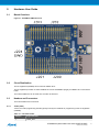
Table 2-5. J201 I/O Low Header
2.3.5
J201 pin
ATSAMD10 pin
Note
J201-1
PA11/RxD
D0
Target USART Receive Pin. SERCOM0
J201-2
PA10/TxD
D1
Target USART Transmit Pin. SERCOM0
J201-3
PA16
D2
J201-4
PA17
D3
J201-5
PA27
D4
J201-6
PA25
D5
PWM TCC1/WO[5]
J201-7
PA30
D6
PWM TC2/WO[0]
J201-8
PA31
D7
PWM TCC0/WO[7]
Target Analogue I/O (J203)
The ATSAMD10 analogue I/O pins are available in the J203 header.
Table 2-6. J200 Analogue Header
2.3.6
J203 pin
ATSAMD10 pin
J203-1
PA02
AIN[0]
J203-2
PA03
AIN[1]
J203-3
PA04
AIN[2]
J203-4
PA05
AIN[3]
J203-5
PA06
AIN[4]
J203-6
PA07
AIN[5]
Power (J202, J300, J301)
The J300 and J301 headers enables selection of power sources and target supply power, the J202 header
enables connection to the power system.
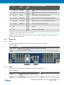
Table 2-7. J202 Power Header
2.3.6.1
J202 pin
Signal
Description
1
NC.
2
VCC_TARGET
ATSAMD10 supply voltage.
3
RESET_SENSE
RESET from external source, monitored by the mEDBG, if pulled low the
target RESET line will be pulled low. This functionality is NOT available
during a debugging session.
4
VCC_P3V3
3.3V from on-board DC/DC converter (U300).
5
VCC_P5V0
Voltage from the selected power source, default VBUS.
6
GND
7
GND
8
VCC_VIN
The externally connected power source if any.
Power Supply Configuration
The J300 and J301 headers enables Power supply configuration.
ATSAMD10 Xplained Mini User Guide [USER GUIDE]
42387A-MCU-01/2015
9