1
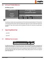
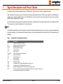
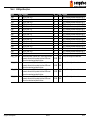
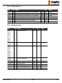
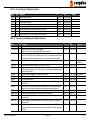
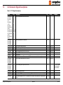
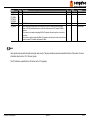
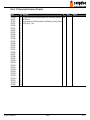
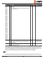
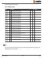
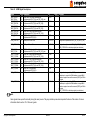
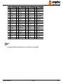
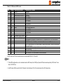
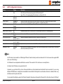
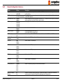
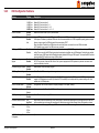
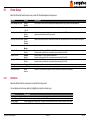
Table 19 IDE Signal Descriptions
Signal
IDE_D0
IDE_D1
IDE_D2
IDE_D3
IDE_D4
IDE_D5
IDE_D6
IDE_D7
IDE_D8
IDE_D9
IDE_D10
IDE_D11
IDE_D12
IDE_D13
IDE_D14
IDE_D15
IDE_A[0.2]
IDE_IOW#
IDE_IOR#
IDE_REQ
IDE_ACK#
IDE_CS1#
IDE_CS3#
IDE_IORDY
IDE_RESET#
IDE_IRQ
IDE_CBLID#
Pin #
D7
C10
C8
C4
D6
D2
C3
C2
C6
C7
D3
D4
D5
C9
C12
C5
D13-D15
D9
C14
D8
D10
D16
D17
C13
D18
D12
D77
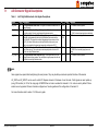
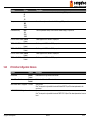
Description
I/O
Address lines to IDE device.
I/O write line to IDE device. Data latched on trailing (rising) edge.
I/O read line to IDE device.
IDE Device DMA Request. It is asserted by the IDE device to request a data transfer.
IDE Device DMA Acknowledge.
IDE Device Chip Select for 1F0h to 1FFh range.
IDE Device Chip Select for 3F0h to 3FFh range.
IDE device I/O ready input. Pulled low by the IDE device to extend the cycle.
Reset output to IDE device, active low.
Interrupt request from IDE device.
Input from off-module hardware indicating the type of IDE cable being used. High indicates a
40-pin cable used for legacy IDE modes. Low indicates that an 80-pin cable with interleaved
grounds is used. Such a cable is required for Ultra-DMA 66, 100 and 133 modes.
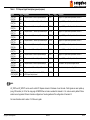
O 3.3V
O 3.3V
O 3.3V
I 3.3V
O 3.3V
O 3.3V
O 3.3V
I 3.3V
O 3.3V
I 3.3V
I 3.3V
Bidirectional data to / from IDE device.
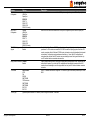
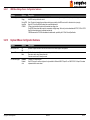
I/O 3.3V
PU/PD
IDE_D7 PD 10k
Comment
PD 5k1
PU 4k7 3.3V
PD 10k
PD 1k
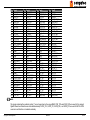
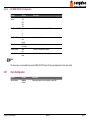
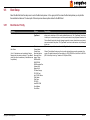
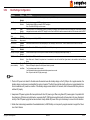
Note
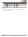
The PATA (IDE) interface is an option conga-BM45. When this option is used, Serial ATA channel 3 is not available.
Copyright © 2008 congatec AG BM45m11 56/103