1
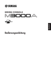
Betriebsanleitung
Operating instructions
Instructions d’emploi
IsoPro B TNS 25/100 (/FM)
Blitz- und Überspannungsableiter
Anforderungsklasse B
Art. Nr. 381 220 (381 221)
IsoPro B TNS 25/100 (/FM)
Lightning and surge protection
Requirement class B
Art. No. 381 220 (381 221)
IsoPro B TNS 25/100 (/FM)
Parafoudre
Classe B
No. de commande 381 220 (381 221)
Beschreibung
Description
Description
Bei diesem Blitz- und Überspannungsableiter handelt es sich um eine
gasgefüllte Trennfunkenstrecke ohne
Ausblasöffnung. Der IsoPro B TNS
25/100 ist ein vierpoliger Kombi-Ableiter
zum Schutz gegen das Eindringen von
Blitzteilströmen in die elektrische
Anlage. Das Gerät dient dem
Blitzschutzpotentialausgleich im
230V/400V~ TNS-Netz.
Installations- und Betriebshinweise
This lightning and surge protector is a
gas-filled spark gap without blow-out
vent. The IsoPro B TNS 25/100 is a
four-pole lightning current protector for
protection against the penetration of
lightning currents into the electrical
system. The device provides lightning
protection equipotential bonding in the
230V/400V~ TNS- net system.
Dans le cas de ce parafoudre, il s’agit
d’un éclateur isolant à étincelles à gaz
rare, sans ouverture d’évacuation. Le
IsoPro230/400Tr/25kA est un
parafoudre unipolaire destiné à la
protection contre l’infiltration de
courants partiels de foudre dans
l’installation électrique. L’appareil sert à
la compensation de potentiel du
parafoudre pour 230V/400V~.
Directives d’installation et d’exploitation
Die Verwendung einer geschlossenen
Hochleistungs-Funkenstrecke (gasgefüllt) macht eine Ausblasöffnung
überflüssig. Ein Sicherheitsabstand zu
benachbarten Komponenten aus
Brandschutzgründen ist nicht erforderlich.
The use of a closed, high-performance
spark gap (gas-filled) renders the blowout vent superfluous. A safety gap
between adjacent components for fire
protection reasons is unnecessary.
Der Einsatzort ist normalerweise der
Hauptverteiler direkt am Gebäudeein gang. Die Schutzschaltung befindet sich
in einem Aufschnappgehäuse für
35 mm Hutschienenmontage (gemäss
EN 50022) mit Multifunktionsan schlussklemmen für Leiter- und
Kammschienenanschluss.
The place of installation is normally the
main distributor at the building entrance.
The protection circuit is contained in a
snap-on housing for installation on
35mm rail (in compliance with EN
50022) with multi-function terminals for
wires and wiring bridges.
Da dieser Ableiter Blitzströme von bis
zu 25 kA (10/350 µs) pro Phase ableiten muss, ist es empfehlenswert,
eindrähtige Cu-Leitungen von 50 mm²
zu verwenden. Die Anschlüsse sind
vorzugsweise mit 4.5 Nm anzuziehen.
Die Gesamtlänge der Leitungen darf
0.5 m nicht überschreiten. Andernfalls
sollte die PE-Leitung mit einer zu sätzlichen Klemme möglichst V-förmig
installiert werden.
Dieses Gerät darf nicht ausschliesslich
über den Kammschienenanschluss
kontaktiert werden. Die Klemmen
müssen auf jeden Fall bedrahtet
werden.
Geschützte und ungeschützte
Leitungen dürfen nicht zusammen
verlegt werden.
15.11.2004
© copyright 2004 by
Leutron GmbH
Technische Änderungen und
Lieferbedingungen vorbehalten
Installation / operating instructions
L’utilisation d’un éclateur à haute
performance fermé (à gaz rare) rend
une ouverture d’évacuation superflue.
Pour des raisons de protection contre
l’incendie, un intervalle de sécurité par
rapport aux composants avoisinants
n’est pas requis.
Le lieu d’application est normalement le
distributeur principal, directement à
l’entrée du bâtiment. Le circuit de
protection se trouve dans un boîtier à
verrouillage ressort pour le montage
d’un rail profilé chapeau 35mm (selon
EN 50022) avec bornes de raccordement multifonctionnelles pour la conneAs these protectors have to discharge
xion de conducteurs et de cavaliers
lightning currents of up to 25 kA (10/350 (jumper)
µs) per phase, we recommend the use
Etant donné que ce parafoudre doit
of single-wire copper lines of 50 mm².
décharger des courants de foudre
Connections should preferably be
jusqu’à 25 kA (10/350 µs), il est
tightened to 4.5 Nm.
recommandé d’utiliser des lignes de
The entire length of the lines should not cuivre unifilaires de 50 mm². Les
exceed 0.5 m. But if it does, the PE line raccordements sont à serrer de
préférence avec 4.5 Nm.
should be installed with an additional
terminal, as V-shaped as possible.
La longueur totale des lignes ne doit
This device must not be bonded
pas dépasser 0.5 m. Le cas échéant, la
exclusively via the wiring bridge.
ligne PE sera installée avec une borne
supplémentaire en forme de ‘ V ’ si
Lightning currents must be discharged
possible.
via a wire with an adequate crosssectional area.
Cet appareil ne doit pas exclusivement
Protected and unprotected lines must
être connecté par l’intermédiaire du
not be laid together.
raccordement à cavaliers. Les courants
de foudre doivent être déchargés par
l’intermédiaire d’un conducteur de
section suffisante. Les lignes protégées
et les lignes non protégées ne doivent
pas être posées ensemble.
Leutron GmbH
Überspannungsschutz
Humboldtstr. 30
D-70771 Leinfelden Echterdingen
Tel: +49 711 9 47 71 0
Fax: +49 711 9 47 71 70
Email: [email protected]
Web: www.leutron.de
Betriebsanleitung
Operating instructions
Instructions d’emploi
IsoPro B TNS 25/100 (/FM)
Art. Nr. 381 220 (381 221)
IsoPro B TNS 25/100 (/FM)
Art. No. 381 220 (381 221)
IsoPro B TNS 25/100 (/FM)
No. de cde. 381 220 (381 221)
Wartung
Maintenance
Maintenance
Es ist empfehlenswert, die Anschlüsse
dieses Ableiters nach jeder Blitzsaison
nachzuziehen. Ansonsten ist dieses
Produkt wartungsfrei.
We recommend that after the period
when thunderstorms are most frequent, the connections for this lightning current protector be retightened.
Apart from that this product requires no
maintenance.
Trouble-shooting
Il est recommandé de resserrer les
raccordements de ce parafoudre après
chaque période orageuse. Cela mis à
part, ce produit est exempt de
maintenance.
Fehlererkennung
Reconnaissance de défauts
Bei Bedarf kann dieser Ableiter durch
eine Isolationsmessung überprüft
werden. Bei Risol 0.5 .. 1 MΩ sollte der
Ableiter bei der nächsten Gelegenheit
ersetzt, bei Risol < 0.5 MΩ sofort
ausgewechselt werden.
As and when required, this surge
protector can be checked by measuring insulation. With an insulation
resistance of 0.5 ... 1 MΩ the protector should be replaced at the next
opportunity. With an insulation resistance of <0.5 MΩ the surge protector
must be replaced immediately.
Au besoin, ce parafoudre peut être
vérifié par une mesure d’isolation. Pour
une résistance d’isolement de 0.5 .. 1
MΩ, le parafoudre devra être remplacé à
la prochaine occasion ; pour une
résistance d’isolement < 0.5 MΩ, il doit
immédiatement être échangé.
Achtung
Important
Attention
Der IsoPro B TNS 25/100 darf nur von
Elektrofachleuten unter Beachtung der
geltenden Normen montiert und installiert
werden.
The IsoPro B TNS 25/100 may only be
mounted and installed by electronics
specialists in compliance with the
applicable standards.
Le IsoPro B TNS 25/100 ne doit être
monté et installé que par des électriciens
spécialisés et en respectant les normes
en vigueur.
Technische Daten
Bemessungsspannung .......
Ansprechstossspannung.....
Blitzstossstrom...................
Isolationswiderstand...........
Max. Vorsicherung..............
Schutzart............................
........................
Technical data
Max. AC operating voltage..
Impulse spark-over voltage.
Lightning impulse current....
Insulation resistance...........
Max . permissible fuse........
Protection category.............
Connections.......................
Abmessungen / dimensions / dimensions
Données
Tens. alt. max. de service........
Tension d’amorçage au choc...
Courant de choc de foudre.......
Résistance d’isolement............
Fusible max. admissible..........
Mode de protection..................
Raccordements.......................
Technische Änderungen und
Lieferbedingungen vorbehalten
≤ 255 Veff
≤ 4 kV
25 kA /12.5 As
> 10^10 Ω
≤ 160 A
IP 20
50 mm²
Anwendungsbeispiel / Application example / Exemple d’application
Schema / diagram / schéma
15.11.2004
© copyright 2004 by
Leutron GmbH
(50 Hz).......
(1.2/50 µs)..
(10/350 µs)
(100 V).......
gL..............
..................
max...........
Leutron GmbH
Überspannungsschutz
Humboldtstr. 30
D-70771 Leinfelden Echterdingen
Tel: +49 711 9 47 71 0
Fax: +49 711 9 47 71 70
Email: [email protected]
Web: www.leutron.de