1
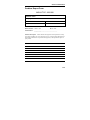
MOXA TCC-100/100I User’s Guide Sixth Edition, September 2006 www.moxa.com/product MOXA Technologies Co., Ltd. Tel: +886-2-8919-1230 Fax: +886-2-8919-1231 Web: www.moxa.com MOXA Technical Support Worldwide: [email protected] The Americas: [email protected] P/N: 1802001000300 MOXA TCC-100/100I User’s Guide Any software described in this manual is furnished under a license agreement and may be used only in accordance with the terms of that agreement. Copyright Notice Copyright © 2006 MOXA Technologies Co., Ltd. All rights reserved. Reproduction without permission is prohibited. Trademarks MOXA is a registered trademark of The MOXA Group. All other trademarks or registered marks in this manual belong to their respective manufacturers. Disclaimer Information in this document is subject to change without notice and does not represent a commitment on the part of MOXA. MOXA provides this document “as is,” without warranty of any kind, either expressed or implied, including, but not limited to, its particular purpose. MOXA reserves the right to make improvements and/or changes to this manual, or to the products and/or the programs described in this manual, at any time. Information provided in this manual is intended to be accurate and reliable. However, MOXA assumes no responsibility for its use, or for any infringements on the rights of third parties that may result from its use. This product might include unintentional technical or typographical errors. Changes are periodically made to the information herein to correct such errors, and these changes are incorporated into new editions of the publication. Table of Contents Chapter 1 Introduction...........................................1-1 Overview .............................................................. 1-2 Product Features ................................................... 1-4 Package Checklist................................................. 1-4 Product Specifications .......................................... 1-4 Schematic ............................................................. 1-6 LED Indicators ..................................................... 1-6 Chapter 2 Installation.............................................2-1 Hardware Installation ........................................... 2-2 Termination Resistor Diagram.............................. 2-7 Function Diagram................................................. 2-7 Isolation Block Diagram....................................... 2-8 Typical Applications ............................................. 2-8 Appendix A Service Information ............................. A-1 MOXA Internet Services ......................................A-2 Problem Report Form ...........................................A-3 Product Return Procedure.....................................A-4 1 C h a p t e r 1 Introduction The TCC-100 and TCC-100I are RS-232 to RS-422/485 media converters. The TCC-100I provides 2 KV of optical isolation. The following topics are covered in this chapter: Overview Product Features Package Checklist Product Specifications Schematic LED Indicators MOXA TCC-100/100I User’s Guide Overview Introduction Many of the important devices used as part of today’s industrial applications are RS-232 devices. This is because RS-232 hardware is relatively easy to design, and RS-232 devices can be readily connected to most PCs. The drawback is that RS-232 is a point-to-point interface, and it imposes a distance limitation of only 15 meters between the device and the computer. To overcome these limitations, many users employ RS-232 to RS-422/485 converters that allow RS-232 devices to connect to an industrial RS-422 or RS-485 network and transmit data over distances up to 1.2 km. The RS-422/485 standards overcome the distance limitation by using a differential signal for transmitting data and control signals. Transmission distance and multi-drop connections are not the only issues of importance for industrial applications In addition, housing, wiring, power supply, and over-surge protection are also important issues. The TCC-100I provides isolation protection for users who need an industrial grade interface conversion product to extend RS-232 transmission distance and increase networking capability. The superior industrial design, which includes DIN-Rail mounting, terminal block wiring, external terminal block power, and optical isolation for system protection, makes the TCC-100I suitable for use in critical industrial environments. Simply put, your RS-232 devices can be used as part of an industrial RS-422/485 network, but without any hardware or software changes. 1-2 Introduction RTS/CTS RS-422 Handshaking Signals The TCC-100/100I provides RS-422 handshaking signal support. The RTS and CTS signals help solve the RS-422 signal handshaking problem and reduce data transmission errors. Built-in RS-485 ADDC™ Intelligence ADDC™ (Automatic Data Direction Control), a MOXA leading technology, uses a clever hardware solution to manage RS-485’s data flow control problem. ADDC™ is a hardware data flow solution that automatically senses and controls data direction, making the handshaking signal method obsolete. Isolation MOXA’s electrical isolation technology uses two photo couplers to create a gap in each electrical signal. One photo coupler transforms the electrical signal into an optical signal, which is transmitted across a small gap, and then the other photo coupler transforms the optical signal back into an electrical signal. In this way, the two electrical circuits are completely isolated from each other, limiting the damage that could otherwise be caused by power surges in the electrical signal. Reverse Power Protection The Reverse Power Protection feature provides extra protection against accidentally connecting the power cables to the wrong terminal. The converter is designed to detect automatically which power wire is positive and which is negative, and then adjust the power supply accordingly. DIP Switch Selectable Terminator For many products of this type, the termination resistor is set by a jumper located inside the product’s casing, so that the user must open the casing to disable or change the resistor’s strength. MOXA offers a better solution. The TCC-100/100I’s terminator is set with a DIP Switch located on the outside of the converter’s casing. Auto Baudrate Detection The TCC-100/100I incorporates a method for automatically detecting the serial signal’s baudrate by hardware. This is an extremely convenient feature for the user. Even if a device’s baudrate changes, the signal will still be transmitted through the RS-232 to RS-422/488 converter without any problem. 1-3 MOXA TCC-100/100I User’s Guide Product Features • RS-232 to RS-422 conversion with RTC/CTS support • RS-232 to 2/4-wire RS-485 conversion • Detachable wall and DIN-Rail mounting attachments for easy RS-422/485 wiring • PWR, Tx, and Rx LEDs • 16 KV ESD Surge Protection • 2 KV Isolation (TCC-100I) for both power and RS-422/485 signals • Operating temperature from -20 to 60°C Package Checklist Before installing the MOXA TCC-100/100I, verify that the package contains the following items: • TCC-100 or TCC-100I • User’s Manual (this document) • Warranty Booklet Please notify your sales representative if any of the above items is missing or damaged. Product Specifications Model Names Communication RS-232 Signal RS-422/485 Signal RS-485 Data Direction Control Baudrate Surge Protection Isolation Environment Operating Temp. Storage Temp. 1-4 TCC-100, TCC-100I Female DB9 connector (Supports Tx, Rx, DTR, DSR, RTS, CTS, DCD) Terminal block connector (DIP Switch selectable) 4-wire RS-422 (with RTS/CTS): up to 10 nodes (1.2 km) 4-wire RS-485: up to 32 nodes (1.2 km) 2-wire RS-485: up to 32 nodes (1.2 km) ADDC™ 50 bps to 921.6 Kbps 16 KV ESD RMS, for all signals 2 KV (TCC-100I) for both power and signal -20 to 60°C (-4 to 140°F) -20 to 85°C (-4 to 185°F) Introduction Humidity 5 to 95%RH Power Input Power Voltage Reverse Power Protection Over Current Protection Power Consumption External Power 12 to 48 VDC, Terminal Block Protects against V+/V- reversal Protects against 2 signals shorted together 400 mA (max.) at 12V Mechanical Dimensions (W × D × H) 67 × 100 × 22 mm (without DIN-Rail mounting kit) 90 × 100 × 22 mm (with DIN-Rail mounting kit) Aluminum #22 – #16 AWG Case Plug-In Screw Terminal Block Weight 148±5 g Regulatory Approvals CE, FCC (Class B) WARNING 1. 2. 3. This unit is not meant to be sold to consumers. It will only be shipped to manufacturers or factories. The DC source should come from an external adapter or 12 to 48 VDC source (not from DC mains) by using a transfer device. This unit should be installed or set up by a qualified service person. 1-5 MOXA TCC-100/100I User’s Guide Schematic 11.5 mm 22 mm 67 mm 100.4 mm 28.7 mm O7 43 mm O3.5 O4 28.7 mm LED Indicators TCC-100/100I’s top panel contains three LED indicators, as described in the following table: LED Name LED Function PWR Green indicates the TCC-100/100I is receiving data from the RS-232 port. Yellow indicates the TCC-100/100I is receiving data from the RS-422/485 port. 1-6 RED Red indicates the power is on. GREEN YELLOW PWR 2 Chapter 2 Installation In this chapter, we explain how to install the TCC-100/100I, and show function and block diagrams. The following topics are covered in this chapter: Hardware Installation Termination Resistor Diagram Function Diagram Isolation Block Diagram Typical Applications MOXA TCC-100/100I User’s Guide Hardware Installation Installing the TCC-100/100I involves five straightforward steps: STEP 1: Set the DIP Switches STEP 2: Attach the Power Supply STEP 3: Wire the Terminal Block STEP 4: Attach the RS-232 Converter STEP 5: Test the Connection The details of each of these five steps are described next. STEP 1: Set the DIP Switches The DIP Switches on the TCC-100/100I are used to set the signal transmission mode and enable or disable the termination resistor. You can configure the TCC-100/100I to use either RS-422 or RS-485 transmission. Your program and serial port should be set to match the converter’s settings. SW1—Switch 1 selects RS-422 or RS-485 mode. The default is “On” for RS-422 mode. SW2—Switch 2 selects 2-wire or 4-wire RS-485 mode. The default is “On” for 4-wire RS-485. Note that if Switch 1 is set to RS-422 mode, then Switch 2 is inactive. SW3—Switch 3 enables the terminator to 120 Ohms. When enabled, the 120 Ohm resistor prevents signal reflection during RS-485 transmission. The default is “On” to enable the terminator. If your particular application does not require using the termination resistor, then simply set Switch 3 to the off position to disable it. 2-2 Installation Dip Switch Settings RS-422, Terminator active SW1 SW2 SW3 ON ON ON SW1 SW2 SW3 ON ON OFF SW1 SW2 SW3 OFF ON ON SW1 SW2 SW3 OFF ON OFF SW1 SW2 SW3 OFF OFF ON SW1 SW2 SW3 OFF OFF OFF 1 2 3 1 2 3 1 2 3 1 2 3 1 2 3 1 2 3 RS-422 4-wire RS-485, Terminator active 4-wire RS-485 2-wire RS-485 with Terminator 2-wire RS-485 2-3 MOXA TCC-100/100I User’s Guide The newly implemented DIP-2 Switches are used to configure the pull high/low resistors for different applications. Pull High/Low Resistor 150K (default) 1K NOTE 2-4 DIP-2 SW1 OFF ON DIP-2 SW2 OFF ON We recommend setting the pull high/low resistor to 1K (ON/ON) when termination is enabled. Installation V+ V- STEP 2: Attach the Power Supply The TCC-100/100I is powered by an external 12 to 48 VDC power supply. To connect the power supply, run two wires from the V+ and V- terminals on the TCC’s 3-connector terminal block to the DC power supply, as shown in the figure. Once the power supply is connected to its power source, the Power Supply PWR LED located on the TCC’s top + 12 - 48 VDC panel will illuminate in red. NOTE: The TCC-100/100I provides reverse power protection. It will automatically detect which power wire is negative, and which is positive. STEP 3: Wire the Terminal Block There are three wiring options available for connecting to the TCC-100/100I’s RS-422/485 terminal block. Data + Data - SGND Rx+ RxTx+ Tx- SGND Tx+(B) Tx-(A) Rx+(B)(Data+) Rx-(A)(Data-) RTS+(B) RTS-(A) CTS+(B) CTS-(A) SGND Tx+(B) Tx-(A) Rx+(B)(Data+) Rx-(A)(Data-) RTS+(B) RTS-(A) CTS+(B) CTS-(A) SGND 2-wire RS-485 When using the 2-wire RS-485 wiring option, connect three wires from the TCC-100/100I’s terminal block to the opposite connection. As shown in the figure, connect from Data+ to Data+, from Data- to Data-, and from SGND to SGND. 4-wire RS-485 When using the 4-wire RS-485 wiring option, connect five wires from the TCC-100/100I’s terminal block to the opposite connection. As shown in the figure, connect from Tx+(B) to Rx+, from Tx-(A) to Rx-, from Rx+(B) to Tx+, from Rx-(A) to Tx-, and from SGND to SGND. 2-5 MOXA TCC-100/100I User’s Guide Rx+ RxTx+ TxCTS+ CTSRTS+ RTSSGND Tx+(B) Tx-(A) Rx+(B)(Data+) Rx-(A)(Data-) RTS+(B) RTS-(A) Optional CTS+(B) CTS-(A) SGND STEP 4: Attach the RS-232 Connector Depending on your application, use the appropriate serial cable to connect from the TCC-100/100I’s RS-232 female DB9 port to your RS-232 device, or to your computer’s COM port. RS-422 When using the RS-422 wiring option, first follow the 4-wire RS-485 wiring instructions given above. Optional RTS/CTS Handshaking Signals If your software is set up to send and receive RTS/CTS signals over separate wires, you should also connect from RTS+(B) to CTS+, from RTS-(A) to CTS-, from CTS+(B) to RTS+, and from CTS-(A) to RTS-. Female DB9 5 4 9 3 8 2 7 1 6 PIN RS-232 1 DCD 2 TxD 3 RxD 4 DSR 5 GND 6 DTR 7 CTS 8 RTS 9 --- RS-232 Pin Assignment Diagram STEP 5: Test the Connection After setting the DIP Switches, connecting the power, wiring the terminal block, and attaching the RS-232 connector, we suggest using a console terminal program, such as HyperTerminal or MOXA Terminal Emulator, to test the connection. If you have an RS-422/485 serial board (such as the MOXA CP-132, a 2-port RS-422/485 board) installed in your PC, you can connect your PC’s COM port to the TCC-100/100I’s RS-232 port, and then connect the TCC-100/100I’s RS-422/485 terminal block to one of the RS-422/485 serial board’s ports. Alternatively, if you have already set up an RS-422 or RS-485 network, you can also connect the TCC-100/100I’s RS-422/485 terminal block directly to that network. Next, start HyperTerminal or MOXA Terminal Emulator, and then open a connection to both the COM port, and the port associated with the TCC-100/100I’s RS-422/485 port. Simply type a few characters on your PC’s keyboard. The characters you type should show up in the HyperTerminal window that is currently inactive, indicating that the typed characters were transmitted between the TCC-100/100I’s RS-232 port and RS-422/485 terminal block connector. 2-6 Installation Termination Resistor Diagram Termination is designed to Termination Resistor: mitigate noise from the S3 On to Enable S3 Off to Disable RS-422/485 transmission signals. If the network cable is R too long, undesirable transmission-line effects will RxD+ arise. The best method for RxDmitigating energy on an unused conductor is to dissipate the energy as heat by terminating both ends of the unused conductor to ground with resistors (so-called bi-directional termination). The resistance of the resistors should be equal to the characteristic impedance of the line. The most common RS-485 twisted pair has a characteristic impendence of 100-120 Ohm. MOXA’s termination technique is bi-directional termination, which offers excellent signal integrity. With this technique, the line drivers can be located anywhere on the network. RS-422/485 Line Driver ADDC Logic TxD+ TxDRxD+ (Data +) RxD- (Data -) RS-422 RS-232 Line Driver Communication Controller TxD RxD RTS CTS GND RS-485 Function Diagram Isolation 2-7 MOXA TCC-100/100I User’s Guide Isolation Block Diagram Typical Applications RS-485 Application A typical RS-485 application for the TCC-100/100I is depicted in the following figure. In this scenario, two TCC-100I units are used to connect two PCs to an RS-485 network. The third TCC-100I is used to connect the PLC—which is designed for the RS-232 interface—to the RS-485 network. In this way, both of the PCs are able to interact with the PLC and the LCD Display. Rx+(B)(Data +) V DC9~30V RS -232 V+ TCC-100 RS- 422/485 CTS (A) SGND Transioʳ RTS (A) RS-232 to RS-422/485 converter Rx (A)(Data ) RTS+(B) CTS+(B) R PWR Tx (A) RS-232 Tx Tx+(B) RS-232 Rx T RS-232 Tx (A) Tx+(B) RS -232 RS- 422/485 Rx+(B)(Data +) Transioʳ Rx (A)(Data ) RS-232 to RS-422/485 converter DC9~30V RTS+(B) RS-232 Tx V V+ RTS (A) PWR RS-485 Network CTS (A) RS-232 Rx R T MOXA TCC-100I LCD Display Rx+(B)(Data +) DC9~30V TCC-100 V RS -232 V+ RS- 422/485 CTS (A) SGND Transioʳ RTS (A) RS-232 to RS-422/485 converter Rx (A)(Data ) RTS+(B) CTS+(B) R RS-232 Tx Tx (A) PWR Tx+(B) RS-232 Rx T MOXA TCC-100I 2-8 PC CTS+(B) RS-232 PC SGND TCC-100 MOXA TCC-100I RS-232 PLC Installation RS-422 Application Rx (A)(Data ) Rx+(B)(Data +) Tx (A) Tx+(B) RS -232 RS- 422/485 RTS+(B) Transioʳ RTS (A) RS-232 to RS-422/485 converter DC9~30V CTS (A) CTS+(B) RS-232 Tx V V+ SGND PWR V DC9~30V TCC-100 MOXA TCC-100I V+ RS -232 SGND RS-422 Point-to-Point Communication RS- 422/485 RTS (A) CTS (A) Transioʳ Rx (A)(Data ) RTS+(B) CTS+(B) RS-232 to RS-422/485 converter RS-232 Rx Tx (A) RS-232 Tx PC Tx+(B) Rx+(B)(Data +) PWR RS-232 Rx(+/-) Tx(+/-) w/ optional RTS/CTS RS-232 Rx TCC-100 A typical RS-422 application for the TCC-100/100I is depicted in the following figure. In this scenario, two TCC-100I units are used to create a point-to-point connection between a PC and a scales. The advantage of using two TCC-100I units to convert from RS-232, to RS-422, and then back to RS-232, is that the RS-422 cable connecting the two converters can be up to 1.2 km in length (this is quite an improvement compared to the 15-m distance limitation imposed by the RS-232 interface). MOXA TCC-100I Scales 2-9 A Appendix A Service Information In this appendix, we show you how to contact MOXA for information about this and other products, and how to report problems. The following topics are covered: MOXA Internet Services Problem Report Form Product Return Procedure MOXA TCC-100/100I User’s Guide MOXA Internet Services Customer satisfaction is our number one concern, and to ensure that customers receive the full benefit of our products, MOXA Internet Services has been set up to provide technical support, driver updates, product information, and user’s manual updates. The following services are provided E-mail for technical support: .....................................................support@moxa.com Website for product information:..................................................... www.moxa.com A-2 Service Information Problem Report Form MOXA TCC-100/100I Customer name: Company: Tel: Fax: Email: Date: MOXA Product: Serial Number: TCC-100 TCC-100I ______________________________________ Problem Description: Please describe the symptoms of the problem as clearly as possible, including any error messages you see. A clearly written description of the problem will allow us to reproduce the symptoms, and expedite the repair of your product. A-3 MOXA TCC-100/100I User’s Guide Product Return Procedure For product repair, exchange, or refund, the customer must: Provide evidence of original purchase. Obtain a Product Return Agreement (PRA) from the sales representative or dealer. Fill out the Problem Report Form (PRF). Include as much detail as possible for a shorter product repair time. Carefully pack the product in an anti-static package, and send it, pre-paid, to the dealer. The PRA should be visible on the outside of the package, and include a description of the problem, along with the return address and telephone number of a technical contact. A-4