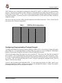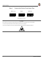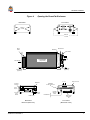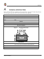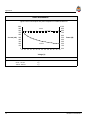
1
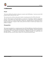
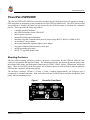
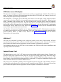
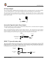
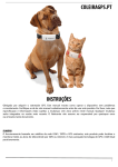
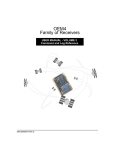
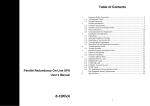
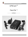
OM-20000004 Rev 3.0
GPSCard ™
PowerPak ™
User Manual
GPSCard™ Products
NovAtel Communications Ltd.
GPSCARD ™ PowerPak
User Manual
Publication Number:
OM-20000004
Revision Level:
Rev. 3.0
94/11/28
Proprietary Notice
No part of this manual may be reproduced or transmitted in any form or by any means, electronic or
mechanical, including photocopying and recording, for any purpose without the express written permission
of a duly authorized representative of NovAtel Communications Ltd.
The information contained within this manual is believed to be true and correct at the time of publication.
The content of this manual is subject to change without notice and does not represent a commitment on the
part of NovAtel Communications Ltd.
Should you have any comments concerning this manual, please do not hesitate to contact NovAtel
Communications, GPS Business Group.
© 1994 NovAtel Communications Ltd. All rights reserved
Unpublished rights reserved under International copyright laws.
Printed in Canada on recycled paper.
ii
GPSCard™ PowerPak™
Table of Contents
TABLE OF CONTENTS
Foreword ................................................................................................................................................................... vii
PowerPak Overview
Mounting Enclosure........................................................................................................................1
PCB Interconnect Backplane..........................................................................................................2
GPSCard™ .....................................................................................................................................2
Internal Power Card........................................................................................................................2
AC Power Adapter..........................................................................................................................3
Automobile Cigarette Lighter Power Adapter................................................................................ 3
RS232 "Y" type null modem cable .................................................................................................3
Hardware Installation ............................................................................................................................................4
Communication Ports...................................................................................................................... 5
Configuring Communications Protocol Formats............................................................................6
I/O Strobes ...................................................................................................................................... 8
Accessing The Power Board Fuse ..................................................................................................8
APPENDICES
A
Technical Specifications .................................................................................................................9
TABLES
Table 1
Table 2
COM Port Pin Configurations ........................................................................................................ 5
I/O Port Pin-Out Description ..........................................................................................................8
FIGURES
Figure 1
Figure 2
Figure 3
Figure 4
Figure 5
PowerPak Front Panel.....................................................................................................................1
Typical PowerPak Installation Configuration ................................................................................ 4
Communication Protocol Format Jumper Plugs .............................................................................6
Opening the PowerPak Enclosure ..................................................................................................7
PowerPak Dimensions .................................................................................................................... 9
GPSCard™ PowerPak™
iii
Customer Service
CUSTOMER SERVICE
If you require customer service, please provide the following information along with a detailed description
of the problem when you call or write:
Serial No.______________________________ Model No. ___________________________________
Software Release No. ____________________ Authorization No. _____________________________
Date Purchased:_________________________
Purchased from:______________________________________________________________________
User name:_____________________________ Title: _______________________________________
Company: __________________________________________________________________________
Address:____________________________________________________________________________
City:__________________________________ Prov/State: ___________________________________
Zip/Postal Code: ________________________ Country:_____________________________________
Phone #:_______________________________ Fax #:_______________________________________
GPSCard interface:
Computer type: ___________________ Operating Shell:___________________
Other interface used: __________________________________________________________________
Please provide a complete description of any problems you may be experiencing, or the nature of your
inquiry (attach additional sheets if needed):
___________________________________________________________________________________
___________________________________________________________________________________
___________________________________________________________________________________
___________________________________________________________________________________
___________________________________________________________________________________
You may photocopy and fax this page, call, or mail the above information to the address listed below.
For customer support, contact the NOVATEL GPS Hotline at 403-295-4900, Fax 403-295-4901, or write to:
NovAtel Communications Limited
GPS Customer Service
6732 - 8th Street N.E.
Calgary, Alberta, Canada
T2E 8M4
iv
GPSCard™ PowerPak™
Warranty Policy
WARRANTY POLICY
NovAtel Communications Ltd. warrants that its Global Positioning System (GPS) products are free from defects in materials and
workmanship, subject to the conditions set forth below, for the following periods of time:
GPSCard™ Series
GPSAntenna™ Series
Cables and Accessories
Software Support
One (1) Year
One (1) Year
Ninety (90) Days
One (1) Year
Date of sale shall mean the date of the invoice to the original customer for the product. NovAtel's responsibility respecting this
warranty is limited solely to product replacement or product repair at an authorized NovAtel location only. Determination of
replacement or repair will be made by NovAtel personnel or by technical personnel expressly authorized by NovAtel for this
purpose.
This warranty will not extend to damage or failure resulting from misuse, neglect, accident, alteration, abuse, improper
installation, non-approved antenna/cables/accessories, or operation in an environment other than that intended.
In no event will NovAtel be liable for any indirect, incidental, special or consequential damages whether through tort,
contract or otherwise. This warranty is expressly in lieu of all other warranties, expressed or implied, including without
limitation the implied warranties of merchantability or fitness for a particular purpose. The foregoing states the entire
liability of NovAtel with respect to the products herein.
There are no user serviceable parts in the GPSCard and no maintenance is required. When the status code indicates that a unit is
faulty, replace with another unit and return the faulty unit to the address listed below.
You must obtain a RETURN MATERIAL AUTHORIZATION (RMA) number by calling GPS Customer Service at
403-295-4900 before shipping any product to NovAtel.
Once you have obtained an RMA number, you will be advised of proper shipping procedures to return any defective product.
When returning any product to NovAtel, please return all original diskettes along with the defective product in the original
packaging to avoid ESD and shipping damage.
GPSCard™ PowerPak™
v
FCC Notice
NOTICE
This equipment has been tested and found to comply with the limits for a class A digital device, pursuant to
Part 15 of the FCC rules. These limits are designed to provide reasonable protection against harmful
interference when the equipment is operated in a commercial environment. This equipment generates, uses,
and can radiate radio frequency energy and, if not installed and used in accordance with the instruction
manual, may cause harmful interference to radio communications. Operation of this equipment in a
residential area is likely to cause harmful interference in which case the user will be required to correct the
interference at his own risk.
Equipment changes or modifications not expressly approved by the party responsible for compliance could
void the user's authority to operate the equipment.
IMPORTANT:
In order to maintain compliance with the limits of a Class A digital device, you are required to use properly
shielded interface cables when using the Strobe Port (I/O).
CAUTION !
Handle with Care
Use Anti-Static Precautions
vi
GPSCard™ PowerPak™
Foreword
FOREWORD
Scope
The NovAtel GPSCard PowerPak User Manual is written for the OEM Purchaser. From here on, the OEM
purchaser shall be referred to as the "user".
This manual provides sufficient information for initial set-up and operation of the GPSCard PowerPak.
The focus of this manual is on the initial OEM user's perspective for integration, evaluation, and operation
purposes. It is beyond the scope of this manual to provide service or repair details. However information is
provided to allow you to open the PowerPak to change the communications port configurations and to
replace the internal fuse, if required. Please contact your NovAtel Service Center for any customer service
problems or inquiries.
Prerequisites
This manual is intended to be a companion manual to the GPSCard OEM Series Installation and Operating
Manual (OM-20000007) and the Command Descriptions Manual (OM-20000008). All specific information
concerning the OEM Series installation and operation is contained in the OEM Series Installation and
Operating Manual. To effectively use and operate the GPSCard PowerPak, it is required that you
thoroughly familiarize yourself with the contents of the Command Descriptions Manual.
GPSCard™ PowerPak™
vii
PowerPak Overview
PowerPak OVERVIEW
The NovAtel GPSCard™ OEM Series has been designed for the OEM developer who intends to design a
GPS navigation or positioning system around the NovAtel GPSCard OEM Series. The GPSCard PowerPak
was produced to simplify the initial set-up required by the OEM developer to facilitate the evaluation
process. The kit provides the following features:
•
•
•
•
•
•
•
•
•
•
a suitable mounting enclosure
one OEM Performance Series GPSCard™
built-in power converter
internal PCB interconnect backplane
internally selectable communication protocol jumper plugs (RS232, RS422, or NMEA 0183)
an external AC power adapter
an external automobile cigarette lighter power adapter
two serial communication ports and a strobe port
an ESD grounding wrist strap
RS232 "Y" type null modem cable
Mounting Enclosure
The PowerPak mounting enclosure provides a protective environment for the GPSCard while the user
carries out operational and interface testing. The mounting enclosure also houses the internal power card,
interconnect back-plane, and front panel connections for COM1, COM2, strobes, GPSAntenna, and power
input. There are two LED's on the front panel; one to indicate power on (red) and one to indicate when the
GPSCard has computed valid position (green).
The enclosure measures 205mm x 111mm x 47mm, weighing approximately one kilogram and is
constructed of extruded aluminum. Each end of the enclosure is sealed with an end plate (front panel, back
panel) and four mounting screws.
Figure 1
PowerPak Front Panel
COM 2
COM 1
POWER
10 - 36V DC
GPSCard™ PowerPak™
I/O
VALID
POSITION
ANT.
1
POWER-Pak Overview
PCB Interconnect Backplane
The interconnect backplane is a printed circuit board vertically mounted directly behind the PowerPak front
panel. Its purpose is to provide direct interconnection between the GPSCard 64–pin connector, power card,
and the front panel input and output connections.
The backplane is an integral part of the front panel where all of the input, output, and interconnect
connectors are directly soldered to it (except the antenna interconnect cable assembly). When the front
panel is mounted to the enclosure box, the GPSCard and power card plug directly into the backplane
completing all required interconnections. When the front panel is removed, both cards can be slid out from
the enclosure while still plugged into the backplane and front panel, or become disconnected by unplugging
the backplane directly from the two cards. Refer to the Installation Section for specific information about
removal of the panels and internal circuit boards.
Also found on the interconnect backplane are two connector headers, J1 and J2. Each header accommodates
six jumper plugs which are used for configuring COM1 and COM2 ports for optional communications
protocol (RS232, RS422, or NMEA 0183). Refer to the Hardware Installation Section for further
information on the jumper plugs.
GPSCard™
The GPSCard is mounted by sliding it into card guides located on each side of the mounting enclosure
(second slot from the top of the enclosure) and is located above the power card. It becomes secured into
place when the backplane connector plugs into it as the front panel is fastened to the enclosure.
All information specific to the GPSCard can be found in the GPSCard OEM Series Installation and
Operating Manual OM-20000007.
Internal Power Card
The internal power card is a DC to DC power converter providing multiple output voltages, filtering, fuse
protection, and voltage regulation for the GPSCard. It will accept a single input voltage between the range
of +10 to +36 VDC and converts it to +5, +12, and -12 VDC which the GPSCard requires to operate. The
power input is reverse polarity protected and utilizes a replaceable 2.0 Amp fuse mounted on the power card
which will blow when an over-current condition occurs.
The power card is mounted by sliding it into card guides located on each side of the mounting enclosure
(second slot from the bottom of the enclosure) and is located below the GPSCard. It becomes secured into
place when the backplane connector plugs into it as the front panel is fastened to the enclosure.
2
GPSCard™ PowerPak™
PowerPak Overview
AC Power Adapter
The AC power adapter supplied with the PowerPak provides a convenient means for converting available
110 VAC (60 Hz) power to 12 VDC which is suitable to drive the PowerPak power converter board.
The output from the power adapter utilizes a standard 2.1 mm plug where the center is a female contact
(positive) and the outer jacket contact is negative and plugs directly into the power jack located on the front
panel of the PowerPak.
Automobile Cigarette Lighter Power Adapter
The cigarette lighter power adapter supplied with the PowerPak provides a convenient means for supplying
+12 VDC while operating from an automobile.
Input is provided through the standard cigarette lighter connector. The output from the power adapter
utilizes a standard 2.1 mm plug where the center is a female contact (positive) and the outer jacket contact is
negative and plugs directly into the power jack located on the front panel of the PowerPak.
4 amp
slow-blow
fuse
Spring
2.1 mm plug
North American head
(factory default)
European head
RS232 "Y" type null modem cable
This cable supplied with the PowerPak provides a convenient means of communications with the OEM
GPSCard from a PC. The cable is equipped with a 9-pin connector at the PowerPak end which can be
plugged into either COM1 or COM2. At the PC end, both a 9-pin and a 25-pin connector are provided to
accommodate most PC serial (RS232) communication ports.
DB9S receptacle
(female)
200 mm ± 25
DB25S receptacle
(female)
1500 mm ± 50
GPSCard™ PowerPak™
DB9S receptacle
(female)
3
Hardware Installation
HARDWARE INSTALLATION
Installing the PowerPak is a straightforward process. A minimum configuration is established with the
following set-up:
•
•
•
•
setting up the GPSAntenna
routing and connecting the antenna cable between the GPSAntenna and PowerPak
connecting an RS232/RS422 or NMEA 0183 communication interface to one of the COM ports of
the PowerPak. (The supplied null modem cable is intended for RS232 communications only!)
connecting the output of the power adapter to the input power jack of the PowerPak.
Refer to the GPSCard OEM Series Installation and Operating Manual for further information on installation
of the GPSAntenna and antenna coaxial cable.
Figure 2
Typical PowerPak Installation Configuration
GPSA ntenna™
TNC
GPSCard
PowerPak™
COM2
COM1
POWER
110 VAC
Input
12 VDC
I/O
Valid
Position
A ntenna Cable
ANT
User
Interface
TNC
2.1 mm plug
'Y' type Null Modem Cable
for RS232 serial communications
Car power adapter
Communication Ports
The PowerPak provides communications from two available ports, COM1 and COM2. These ports are
defaulted to the following communications protocol format:
•
•
•
•
•
•
•
4
RS232
9600 baud
no parity
8 bits
1 stop bit
no hand shaking
echo off
GPSCard™ PowerPak™
Hardware Installation
Each COM port can be individually configured for either RS232, RS422, or NMEA 0183 communications
protocol. The protocol available at each COM port is determined by the jumper plug positions on J1 (for
COM1) and J2 (for COM2). J1 and J2 are located on the backplane printed circuit board, just behind the
PowerPak front panel. If you do not wish to use the default baud rate, use the GPSCard COMn command to
change the setting.
Pin-outs are the same for both COM ports and both ports utilize DB9P connectors. Table 1 below lists the
pin-outs for each COM port configuration.
Table 1
COM1/COM2
DB9P
RS232
Pin 1
Pin 2
Pin 3
Pin 4
Pin 5
Pin 6
Pin 7
Pin 8
Pin 9
DCD
RXD
TXD
DTR
GND
DSR
RTS
CTS
NULL
COM Port Pin Configurations
PROTOCOL FORMAT
RS422
NMEA 0183
RXDRXD+
TXD+
RTSGND
CTSRTS+
CTS+
TXD-
NMEA input B
NMEA input A
NMEA output A
N/A
N/A
N/A
N/A
N/A
NMEA output B
Configuring Communications Protocol Formats
To change the default RS232 protocol format to RS422 or NMEA 0183, it is necessary to change the jumper
plug setting at J1, J2 or both depending on which COM port or ports are to be reconfigured. Both jumper
plugs are located on the backplane interconnect PCB just behind the front panel.
To access the jumper plugs, first ensure the unit is powered off. Then remove the front and rear panels of
the PowerPak. This is accomplished by removing the four corner screws from each of the panels. Then,
access the rear panel opening, using your thumb to push both the GPSCard and Power card forward about
two inches. This will cause the front panel to move forward, exposing the backplane board. Refer to
Figures 3 and 4 for more details.
Locate J1 and J2 headers on the backplane PCB. J1 is the jumper plug header for COM1, and J2 is the
jumper plug header for COM2. Using a set of tweezers (for grasping the jumpers), configure the jumpers
according to the figure below for the protocol required.
GPSCard™ PowerPak™
5
Hardware Installation
Figure 3
RS232
11 9
7 5
Communication Protocol Format Jumper Plugs
RS422
(default)
3 1
11 9
7 5
NMEA 0183
3 1
or
12 10
8 6
4 2
11 9
7
5
3
1
12 10
8
6
4
2
or
12 10
8 6
4 2
(Jumper Options for J1 and J2)
CAUTION !
Be sure that the power plug is disconnected from the PowerPak before you attempt to remove the front panel.
Use anti-static precautions whenever the PowerPak is opened up for any purpose.
Use the NovAtel-supplied wrist strap to properly discharge static build-up before handling the GPSCard.
6
GPSCard™ PowerPak™
Hardware Installation
Figure 4
Opening the PowerPak Enclosure
Back Panel
Front Panel
Remove
screws
Remove
screws
Back
Panel
GPSCard
Back Plane
AA
A
A
A
AA
A
A
AA
A
AA
Front Panel
U311
PowerPak™
Rear bumper
PD301
(Top View)
U312
50
51FDCL5
80
81
J1
J2
Panel screw
(4 places)
Panel screw
(4 places)
J1 J2
GPSCard
2nd slot
from top
Back plane PCB
GPSCard
64 Pin Connector
P1
Spacer
bumper
2nd slot
from
bottom
Power
Card
Power Fuse
Back Panel
Removed (Rear V iew)
GPSCard™ PowerPak™
to GPSCard
Internal
antenna
cable
Power Card
Connector
P2
Front Panel
(Back Plane V iew)
7
Hardware Installation
I/O Strobes
The GPSCard I/O Strobe lines are also available on the PowerPak front panel from the 9 pin DB9S
connector. Refer to Appendix B in the OEM Series Installation and Operating Manual for more details
about the I/O Strobes. The pinout is listed in the table below.
Table 2
Pin Number
pin 1
pin 2
pin 3
pin 4
pin 5
pin 6
pin 7
pin 8
pin 9
I/O Port Pin-Out Description
Pin Description (DB9S)
VARF, variable frequency
1PPS, one pulse per second
MKO, mark output
MKI, mark input
STATUS , valid solutions available *
GND
GND
GND
GND
*This is the same line used to turn on/off the valid position LED light on the panel.
Accessing The Power Board Fuse
As a safety precaution, the power board incorporates a 2.0 amp normal blow fuse. The fuse is located near
the rear of the Power Board.
To access the power fuse, it is necessary to remove the front and back panels of the PowerPak. This is
accomplished by removing the four corner screws from each of the panels. Then access the rear panel
opening; use your thumb to push both the GPSCard and Power cards forward about two inches. This will
cause the front panel to move forward, exposing the backplane board, GPSCard, and the Power Board.
Now, grasp the exposed edges of the GPSCard and Power Board and gently pull directly forward until
approximately 3/4 of both cards are extended beyond the front panel opening. The fuse will now be fully
exposed for checking or replacement. Refer to Figure 4 for more details.
CAUTION !
Be sure that the power plug is disconnected from the PowerPak before you attempt to remove the front panel.
Use anti-static precautions whenever the PowerPak is opened up for any purpose.
Use wrist strap!
8
GPSCard™ PowerPak™
Appendix A
A
TECHNICAL SPECIFICA TIONS
Refer to GPSCard OEM Series Installation and Operating Manual, Appendix B, Technical Specifications.
The following data supersedes OEM Technical Specifications where applicable.
INPUT/OUTPUT CONNECTORS
Antenna
TNC (4.5 Vdc, 25 mA max)
Power
2.1 mm plug (10 - 36 Vdc) centre positive
COM1, COM2
DB9P
Strobes
DB9S
PHYSICAL
Size
208 x 111 x 47 mm
Weight
Approx. 1 kg
MECHANICAL DRAWINGS
AA
AA
AAA
Figure 5
PowerPak Dimensions
Front Panel
47 mm
PowerPak™
(Top V iew)
111 mm
Operating Temperature
AA
208 mm
A
A
AA
A
AA
AA
AA
ENVIRONMENTAL
0° C to +50° C using standard temperature GPS OEM Series
-40° C to +65° C using extended temperature GPSCard OEM Series
Storage Temperature
-40°C to +85°C
Humidity
95% non-condensing
Altitude
5,000 meters
GPSCard™ PowerPak™
9
Appendix A
POWER REQUIREMENTS
Typical current consumption and power dissipation of OEM Evaluation Kit
1000
900
800
Power
10.00
9.00
8.00
700
600
Current (mA)
7.00
6.00
5.00
4.00
3.00
2.00
1.00
0.00
500
400
300
Current
200
100
0
10 12 14 16 18 20 22 24 26 28 30 32
Power (W)
34 36
Voltage (V)
VIBRATION
Operational:
10
10 Hz - 55 Hz
55 Hz - 150 Hz
150 Hz - 500 Hz
5g
2g
1g
GPSCard™ PowerPak™
Notes
We Would Like To Hear From You...
NovAtel Communications Ltd. is committed to providing you, our valued customer, with quality
products and customer service. We would like very much to hear fom you.
When it is convenient for you, take a few moments to fill out the questionnaire below and mail or fax it to the
NovAtel GPS Customer Service Department (403-295-4901). At NovAtel, we value your input.
•
Which products have you purchased from NovAtel GPS?
GPSCard:
OEM Series__________
PC Series _______
GPSAntenna: _____________________
Accessories: ____________________ Other:_______________________________________________
•
Are you satisfied with the performance of these products:
Yes
No
Yes
No
Please explain.
•
Are you satisfied with the level of customer service provided?
Please explain.
•
What influenced you to purchase NovAtel GPS products?
•
Do you have any comments concerning this User Manual?
•
Are there any new features or products that you would like to see from NovAtel GPS?
•
Do you have any other comments or suggestions?
Your name ______________________________ Company ________________________________________
Address/phone number _____________________________________________________________________
________________________________________________________________________________________
GPSCard™ PowerPak™
11
Notes
NOTES
12
GPSCard™ PowerPak™
Notes
NOTES
GPSCard™ PowerPak™
13
SCard ™
P
G
G L O B A L P O S IT IO N IN G
SYSTEM
F C C N O T IC E
T h is d e v ic e c o m p lie s w ith p a rt
1 5 o fth e F C C ru le s O
. p e ra tio n is
s u b je c to th e fo lo w in g tw o
c o n d ito n s :
(1 )th is d e v ic e m a y n o tc a u s e
h a rm fu lin te rfe re n c e a
, n d (2 )th is
d e v ic e m u s ta c c e p ta n y
in te rfe re n c e re c e iv e d ,
in c lu d in g in te rfe e
r n c e th a tm a y
c a u s e u n d e s e
ir d o p e ra tio n .
U S E A N T ISTATC
I
PRECAUT O
I NS
N o v A te lC o m m u n ic a tio n s
L td .
GL OB A L P OS T
I IO N IN G
SYSTEM
F C C N O T IC E
A
2 3 4
d.
1
Lt
v
te
s
No
A
O
U S E A N T I-S T A T IC
PRECAUT O
I NS
NovAt el Com m unicat ions Lt d.
N
5
T h is d e v ic e c o m p lie s w ith p a rt1 5
o fth e F C C ru le s O
. p e ra tio n is
s u b je c to th e fo lo w in g tw o
c o n d io
t n s :
(1 )th is d e v ic e m a y n o tc a u s e
h a rm fu lin te rfe re n c e a
, n d (2 )th is
d e v ic e m u s ta c c e p ta n y
in te rfe re n c e re c e iv e d ,in c lu d in g
in te rfe re n c e th a m
t a y c a u s e
u n d e s ire d o p e ra tio n .
l C
io
t
a
ommunic
n
Printed in Canada
on recycled paper
OM-20000004
Revision 3.0
94/11/28