1
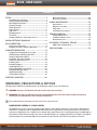
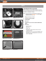
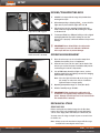
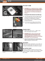
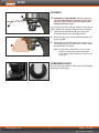
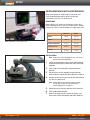
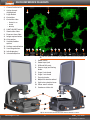
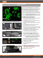
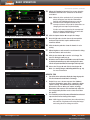
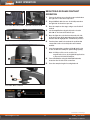
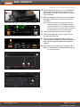
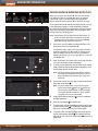
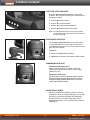
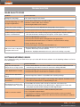
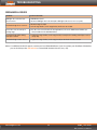
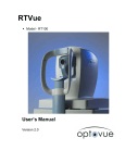
USER GUIDE Digital Inverted Microscope for Fluorescence and Transmitted Light Applications mercury-free energy-efficient amgmicro.com | [email protected] | 866-614-4022 (01-425-368-0444 outside the U.S.) EVOSfl USER GUIDE CONTENTS SETUP.............................................................................. 3 Standard Items Included................................................ 3 Moving/Transporting EVOS........................................... 4 Operating Environment................................................. 4 Mechanical Stage............................................................ 4 LED Light Cubes............................................................. 5 Power Supply.................................................................. 5 USB Ports......................................................................... 5 DVI Output Port.............................................................. 5 UV Shield......................................................................... 6 Installing EVOS in a Cell Culture Hood......................... 7 QUICK-REFERENCE DIAGRAMS................................... 8 BASIC OPERATION......................................................... 9 Fluorescence Operation................................................. 9 Brightfield or Phase Contrast Operation.....................11 Onscreen Controls........................................................ 26 Mechanical Controls.....................................................30 CARE & MAINTENANCE............................................... 32 General Care.................................................................. 32 Objective Lens Care..................................................... 32 Stage Care..................................................................... 32 Sterilization Procedures............................................... 32 TROUBLESHOOTING.................................................... 33 Image Quality Issues.................................................... 33 Software Interface Issues............................................. 33 Mechanical Issues......................................................... 34 CUSTOMER & TECHNICAL SERVICE........................... 35 AMG Contact Information............................................ 35 SPECIFICATIONS..........................................................36 ADVANCED OPERATION..............................................13 Logging In/Creating New User Logins........................13 Saving Images & Working with Files...........................14 Using the QuickSave Option........................................15 Recording Time Lapse Images.....................................16 Using the Transfection Tool..........................................17 Counting Cells................................................................18 Reviewing Images..........................................................19 Using Digital Zoom.......................................................20 Connecting EVOS to a Network...................................21 Changing LED Light Cubes.......................................... 23 Updating Software....................................................... 24 Setting Date and Time ................................................ 25 CONTROLS GLOSSARY................................................26 WARNINGS, PRECAUTIONS & NOTICES Throughout this manual, the following types of notifications require your close attention: ! WARNING! This type of notification tells how to avoid serious personal injury. IMPORTANT! This type of notification tells how to avoid damaging the microscope and/or voiding your warranty (contact your local distributor for more warranty information). This symbol indicates information specific to the color camera version. MONOCHROME CAMERA VS. COLOR CAMERA The EVOS fl microscope is factory-configured with either a monochrome camera or a color camera. Monochrome cameras are commonly used for high-performance fluorescence applications, and provide the best sensitivity for detection of faint fluorescence signals. Color cameras have lower fluorescence sensitivity but have the advantage of being able to differentiate structures by color in transmitted light, e.g., imaging stained tissue samples. Throughout this User Guide, any operational differences between the two versions of the microscope have been noted. © 2012 Advanced Microscopy Group. All rights reserved. Doc Control Number ZP-PKGA-0495 REV C6 Published 4 JUN 2012 SETUP STANDARD ITEMS INCLUDED Before setting up your new EVOS, unpack the unit and accessories and verify all parts are present. Contact your distributor if anything is missing. Note: If you do not have your distributor information, you can look it up at the AMG website or contact AMG Customer Service (see p. 35). LED light cube lock (in place under stage) LED light cubes (in place under LED light cube lock) EVOSfl microscope, per order Accessories Condenser shield, removable Power adapter Dust cover USB flash drive (includes User Guide and Quick Start Guide) • • • • Light shield box USB mouse Power cord UV shield assembly (mount, shield, screws & L-shaped hex key) • Light cube access cover (includes LED light cube installation tool); install light cube access cover before using EVOS Condenser shield, removable Light cube access cover (top) Light cube access cover (bottom, with tool) UV shield assembly kit Light shield box www.amgmicro.com 3 EVOS User Guide fl REV C6 Published 4 JUN 2012 SETUP MOVING/TRANSPORTING EVOS 1 2 Stage lock pin engaged ALWAYS lock stage with the stage lock pin before moving microscope. When transporting or shipping EVOSfl , secure the LED light cubes in place with the light cube lock . Lift the microscope by grasping it firmly with both hands under the support arm , balancing the weight as shown at left. To transport EVOS to a different facility, use the original packaging materials if possible. Always be sure the microscope is properly cushioned and braced to prevent damage. Light cube lock engaged IMPORTANT! Never allow EVOS to be subjected to sudden impact or excessive vibration. Handle the microscope with care to prevent damage. 3 Grasp under support arm with both hands to lift EVOS OPERATING ENVIRONMENT Place the microscope on a level surface away from vibrations from other pieces of equipment. Allow at least 5 cm (2 in) free space at the back of the microscope to allow for proper ventilation and prevent overheating of electronic components. Set up EVOS away from direct light sources, such as windows. Ambient room lighting can enter the imaging path and affect the image. 4 Note: Place the light shield box on the stage over the sample to reduce the effects of ambient light and improve image quality. Light shield box on stage Operating temperature range: 4°–32°C (40°–90°F). IMPORTANT! EVOS should not be subjected to UV sterilization. UV degrades many materials, including plastic. Damage from UV exposure is not covered under the manufacturer’s warranty. Relative humidity range: 30–90%. MECHANICAL STAGE STAGE LOCK PIN Before moving the mechanical stage for the first time, remove the stage lock pin from the back right-hand corner of the stage plate. Pull firmly to remove this pin. You may store the stage lock pin in your accessories box for future use. Note: Always secure the mechanical stage with the stage lock pin before moving the microscope. www.amgmicro.com 4 EVOS User Guide fl REV C6 Published 4 JUN 2012 SETUP LED LIGHT CUBES IMPORTANT! Before changing light channels, ALWAYS be sure the light cube lock has been removed. Applying force to the light cube selection lever while the lock is in place may seriously damage the mechanism. This type of damage is not covered by the manufacturer’s warranty. 1 1. Move the stage back to allow access to the light cube lock , which is centered under the back of the stage. LED light cube lock 2. Loosen the thumbscrew to remove the light cube lock. You may store the light cube lock in your accessories box for future use during transport or shipping. 2 3. Place the light cube access cover into the opening and tighten thumbscrew. Note: For information about adding optional LED light cubes, refer to Changing LED Light Cubes (p. 23). Secure light cube access cover over opening POWER SUPPLY 1. Turn the power switch to the “” (OFF) position before connecting the power adapter. Power switch Power adapter plugged in IMPORTANT! Always use the correct power supply. The power adapter specifications appear on the serial number label (front of LCD hinge) and in the SPECIFICATIONS (p. 36). Damage due to an incompatible power adapter is not covered by warranty. 2. Connect the power adapter to the power jack on the right side of the microscope base, attach the cord to the adapter, and plug the cord into an outlet. USB PORTS Plug the mouse and the USB flash drive into the USB ports located on the bottom right of the support arm. You may also plug in a USB keyboard (not included) for text input. DVI OUTPUT PORT Mouse and USB flash drive plugged in www.amgmicro.com A DVI port is available for output to a projector or other display (DVI cable not included). This port produces digital output only; EVOS is compatible with either a DVI-D or DVI-I display. DVI cable (not included) plugged in 5 EVOS User Guide fl REV C6 Published 4 JUN 2012 SETUP UV SHIELD ! WARNING! UV LIGHT HAZARD! This microscope uses 1 a Class 3B ultraviolet LED for the DAPI channel. Avoid exposure to the UV beam and use protective shields. NEVER look directly at light. 2 For your protection, follow this procedure to install the UV safety shield before using the DAPI fluorescence channel. 1. Attach the UV shield mount to the front of the condenser with the two screws provided. Attach UV shield mount 2. Remove the protective coverings from both surfaces of the UV shield . 3. Place the holes in the UV shield over the screws on the mount and push the slots down on the screws to secure the shield in place, as shown. 3 Note: The UV shield is removable for access to the condenser sliders used in transmitted light mode. Simply unhook it from the screws on the UV mount. UV shield in place CONDENSER SHIELD This shield can help reduce the effects that overhead lighting might have on your image. Condenser shield, removable www.amgmicro.com 6 EVOS User Guide fl REV C6 Published 4 JUN 2012 SETUP INSTALLING EVOS IN A CELL CULTURE HOOD EVOS’ small footprint, simple power connection, and easily-viewed display make it quick to install and convenient to use in a cell culture hood. DIMENSIONS EVOS will fit in cell culture hoods that are at least 20 ½ inches (520 mm) deep. If your cell culture hood is smaller, it may be possible to turn the EVOS at a slight angle to fit. ENGLISH EVOS installed in a cell culture hood METRIC DEPTH 18.5 in 47.0 cm WIDTH 14.0 in 35.5 cm HEIGHT, TRANSPORT 12.75 in 32.4 cm HEIGHT, DISPLAY 22.75 in 57.8 cm WEIGHT 33.7 lbs 15.3 kg INSTALLATION Note: Refer also to the illustrations on p. 4 for more details about moving EVOS. 1. Secure the stage with the stage lock pin, switch EVOS off, and disconnect the power cord, mouse and, if connected, keyboard. 2. Tilt the LCD screen back until it is parallel with the tabletop. 3. Lift the microscope by grasping it firmly with both hands under the support arm just behind the condenser. 4. Gently place the microscope on a lab cart and transport it to the cell culture hood. Note: Verify that the hood sash is raised enough for the microscope to slide underneath (approximately 14” or higher). LCD tilted back into transport position 5. Lift the microscope as before and move it into the hood. 6. Tilt the LCD monitor upright. 7. Remove the stage lock pin, connect the power cord, mouse and, if desired, keyboard, and switch EVOS on. www.amgmicro.com 7 EVOS User Guide fl REV C6 Published 4 JUN 2012 QUICK-REFERENCE DIAGRAMS 1. Channel indicator bar 2. Active channel (highlighted) 3. Login button 4. Control bar 5. Control bar tabs: 1 2 • Find & Focus • Actual • Overlay 6. 7. 8. 9. 10. 11. 12. 13. 14. 15. LIGHT ON/OFF button Illumination slider Exposure time slider Image capture button Color option Scalebar/toolbar options Settings control button Save image button Info display bar* Selected objective 3 4 5 6 7 9 8 10 11 12 13 14 15 *The color camera version shows the QuickSave option instead of the info display bar. 1. 2. 3. 4. 5. 6. 7. 8. 9. 10. 11. 10 Power switch Power input jack USB and DVI ports Coarse stage positioning knobs Stage X-axis knob Stage Y-axis knob Focusing knobs Objective selection wheel Light cube selection lever Phase annuli selector Condenser slider slot 10 11 11 4 6 3 7 6 5 9 7 8 7 1 2 Note: Refer to the CONTROLS GLOSSARY (p. 26) for more details about onscreen and mechanical controls. www.amgmicro.com 8 EVOS User Guide fl REV C6 Published 4 JUN 2012 BASIC OPERATION The EVOSfl microscope uses both mechanical and software controls for operation. Mechanical controls include the stage X-Y axis knobs, focusing knobs, objective selection wheel, and the light cube selection lever. Software controls are located in the control bar at the bottom of the screen. The channel indicator bar at the top of the screen shows the selected filter cube or transmitted light position. The login button displays the current user ID. 2 Refer to the QUICK-REFERENCE DIAGRAMS (p. 8) as needed. See also the CONTROLS GLOSSARY (p. 26) for more details. FLUORESCENCE OPERATION 3 1. Turn on the microscope using the power switch on 1 the right side of the microscope base. 2. Plug a USB flash drive into one of the USB ports on the right side of the microscope arm. Software control bar , channel bar and login button 3. Place the sample on the stage, using a vessel holder if 5 4. 5. Move the light cube selection lever on the left side of 7 the microscope all the way toward you (the channel bar will highlight the “Transmitted” position). 4 Power switch and data ports needed. Set the magnification using the objective selection wheel on the front of the microscope. Light cube selection lever 6. Turn on illumination using the LIGHT ON button , located on the left side of the control bar. 7. Focus the sample using the focusing knobs . 8. Place the light shield box 10 on the stage, over the 6 9 sample. This is important for optimal image quality. Note: If your application requires access to the sample, work in a dark room and use the Block slider to block light reflected from the condenser. 9 Objective selection wheel and focusing knobs 9. Move the light cube selection lever to the desired 8 fluorescence channel (the channel indicator bar will highlight the selected light cube). 10. Click the Find & Focus tab. 11. Click the LIGHT ON button to turn on fluorescence illumination. LIGHT ON button in the control bar !WARNING! UV LIGHT HAZARD! When using the DAPI channel, avoid exposure to beam and use protective shields. NEVER look directly at light. 10 12. Adjust the focus as needed. Light shield box 10 in place on stage continued on next page www.amgmicro.com 9 EVOS User Guide fl REV C6 Published 4 JUN 2012 BASIC OPERATION Fluorescence Operation, continued 1 13. Adjust the illumination intensity if necessary, using the 3 Illumination slider on the control bar or the mouse scroll wheel. Note: When the Color option is off, overexposed pixels will appear red. Dim the illumination until the red highlights disappear to get the maximum level of brightness without any overexposed areas. See p. 28 for instructions on changing the overexposed pixel display. Illumination slider and Capture button in the control bar 2 5 For the color camera version, the overexposed pixels are always highlighted in red unless this feature is disabled in the settings. 14. Click the Capture button to acquire the image. 15. Move the light cube selection lever to the next position Color options (shown for fl monochrome); Save button and repeat steps 10-14 to acquire each fluorescence channel as desired. 4 16. Click the Overlay tab to show all channels in color overlay. Overlay tab 17. Adjust brightness and contrast for each channel to bring them into balance with each other. 6 18. Click the Save button to save the color image. The Save File dialog box will pop up. 19. Click in the Save File Name text field to enter the file name. 8 A virtual keyboard will pop up. After entering the file name, click the Accept button at the lower right of the keyboard. 9 20. Choose the file type and click the Save button . Note:See Saving Images & Working with Files (p. 14) for more information. Save File dialog box HELPFUL TIPS 7 Turn off the Color option to display the image in grayscale. This often shows more detail than a color image. Find & Focus uses a shorter exposure time (100 ms) and lower illumination (appx. 60%) compared to image capture settings. This minimizes photobleaching and phototoxicity effects. When you capture an image, illumination and exposure time automatically adjust for best image quality and then reset to lower levels after the capture. The Actual tab provides full-powered illumination and actual exposure times for live viewing of the sample. Virtual keyboard Note: With longer exposure times (more than 200 ms) there will be a lag between focusing the image and seeing the focus change onscreen. Actual tab www.amgmicro.com 10 EVOS User Guide fl REV C6 Published 4 JUN 2012 BASIC OPERATION BRIGHTFIELD OR PHASE CONTRAST OPERATION 2 1. Turn on the microscope using the power switch on the right side of the microscope base. 4 2. Plug a USB flash drive into one of the USB ports on 1 Power switch and data ports the right side of the microscope arm. Light cube selection lever 3. Place the sample on the stage, using a vessel holder if needed. 4. Set the magnification using the objective selection wheel on the front of the microscope. 5. Move the light cube selection lever on the left side 3 8 of the microscope all the way toward you (the channel indicator bar will highlight the “Transmitted” position). 8 Objective selection wheel and focusing knobs 6. Turn the phase annuli selector to the position that corresponds to the selected objective and contrast method. 7. Insert the appropriate condenser slider into the slot on the condenser assembly for optimal image quality. Note: A Diffuser slider can be used for low magnification (2x or 4x) brightfield applications to improve flat field illumination. BF 5 8. Turn on illumination using the LIGHT ON button , located on the left side of the control bar. 9. Focus the sample using the focusing knobs . Phase annuli selector 6 Insert slider into condenser 7 LIGHT ON button in the control bar continued on next page www.amgmicro.com 11 EVOS User Guide fl REV C6 Published 4 JUN 2012 BASIC OPERATION Brightfield or Phase Contrast Operation, continued 10. When switching from fluorescence to transmitted light with the light shield box on the stage, remove the light shield box cover so the light from the condenser can pass through. 2 1 11. Adjust the illumination intensity if necessary, using the Illumination slider on the control bar or the mouse scroll wheel. Light shield box in place on stage (cover shown in place) 3 Note: Overexposed pixels will appear red. Dim the illumination until the red highlights disappear to get the maximum level of brightness without any overexposed areas. See p. 28 for instructions on changing the overexposed pixel display. 4 12. Click the Capture button to acquire the image. 13. Click the Save button to save the image. The Save File dialog box will pop up. Illumination slider and Capture button in the control bar 14. Click in the Save File Name text field to enter the file 5 name. A virtual keyboard will pop up. After entering the file name, click the Accept button at the lower right of the keyboard. 15. Choose the file type and click the Save button . Note:See Saving Images & Working with Files (p. 14) for more information. Save button 6 8 9 Save File dialog box 7 Virtual keyboard www.amgmicro.com 12 EVOS User Guide fl REV C6 Published 4 JUN 2012 ADVANCED OPERATION LOGGING IN/CREATING NEW USER LOGINS 1 EVOS keeps settings in memory for each user ID, so multiple users can work with the same EVOS microscope without having to reset their preferences. Login button (set to Guest profile) To use this feature, set up a user profile for each regular user. You may also assign user IDs for experiments in progress. Note: User profiles are not password protected. All users should verify they are logged in correctly to avoid changing others’ settings. 5 3 LOG IN WITH AN EXISTING PROFILE 4 1. Click the login button at the bottom left of the screen (this is the AMG logo with the current user profile indicated above). 6 2. Select the desired user profile and click OK . 7 Note: No password is necessary to log in. 2 ADD OR REMOVE A USER PROFILE 1. Click the login button . 2. To copy an existing profile, highlight the profile in the Login dialog box user list , select the “Copy from ‘name’ ” option , and click the Add button . The virtual keyboard will pop up so you can name the new profile. 3. To create a new user profile without copying any settings, deselect the “Copy from” option , click the Add button , and enter a user name. 4. After adding a new user profile, click OK to log in under that name and adjust settings as desired. When you switch off, EVOS will save your settings to memory. Virtual keyboard 5. To remove a user profile, highlight it and click the Remove button . A confirmation dialog box will pop up. Deleting the user profile will remove all its associated settings from memory. 6. To rename a user profile, click the Rename button and enter the new name. 8 CHANGE THE DEFAULT LOGIN The default user login is Guest; to set the default login as the last active user, go to the Basic tab of the Settings dialog box and uncheck the “Default to Guest on startup” option. Note: For multiple users, we recommend leaving the “Default to Guest on startup” option checked. Settings: Basic Tab (to change default login) www.amgmicro.com 13 EVOS User Guide fl REV C6 Published 4 JUN 2012 ADVANCED OPERATION 12 11 SAVING IMAGES & WORKING WITH FILES 1 Save button , Scalebar option 11 , and Display options When you click the Save button , the Save File dialog box appears. If there is no USB flash drive or network connection in place, an information message will appear. Click the Cancel button to clear this message. 12 In the Save Folder list and the saved files list , selected items will appear orange. If a USB keyboard is installed, the virtual keyboard will not appear. Note that pressing the Enter key on a physical keyboard is like pressing the Save button in the Save file dialog box. Note: Saved image files include the date/time stamp. To ensure accurate date/time information, verify the settings before your capture session. See Setting Date and Time (p. 25) for instructions. 2 3 1. Click in the Save File Name text field . Enter a file name and click the Accept button . Save File information message To overwrite a file, simply select the name of the file from the saved files list instead of clicking on the Save File Name text field. A Save As confirmation dialog box will pop up. It is not possible to recover an overwritten file. 6 4 8 16 5 select the destination for the new image. 3. To create a new folder, first click the name of the parent 15 14 14 10 2. Click on the name of a folder in the Save Folder list to 15 16 folder, and then click the New Folder button to enter a folder name and, if desired, date. 13 Note: Clicking the Date button anywhere within a text field will automatically insert the current date (MM-DD-YYYY) wherever the cursor is in that field. Save File dialog box 4. Select a file format (.tif, .png, .jpg or .bmp) from the File Type drop-down menu 17 10 . Note: To save a 16-bit image, select .tif or .png and ensure the Scalebar 11 and Color 12 options are off. File types .jpg and .bmp (as well as images of all types with the Scalebar, or Color options engaged) only save at 8-bit depth. 9 7 Virtual keyboard 5. Click in the Comment text field 13 to enter a comment and date (optional). 6. Click the Save button 14 to save the file. 7. To delete a file or folder, highlight the item on the list and click the Delete button 15 . A confirmation dialog box will pop up. It is not possible to recover a deleted file. Confirmation popup 8. To rename a file or folder, highlight the item on the list and click the Rename button 16 . The virtual keyboard will pop up; you can use the Clear button 17 to reset to a blank field. www.amgmicro.com 14 EVOS User Guide fl REV C6 Published 4 JUN 2012 ADVANCED OPERATION 1 USING THE QUICKSAVE OPTION 13 Settings button and Save button QuickSave allows you to save multiple images under a single base file name. Simply specify the settings and select the QuickSave option, and EVOS will save each image with a single click of the Save button. 13 1. Click the Settings button to open the Settings dialog box, and then select the QuickSave tab. 2. Click in the Base Filename text field and enter a name that describes the imaging session. The orange “Next” file name will reflect the information entered. 2 5 3 3. Click in the Count text field to enter the starting 4 number, if you do not want to start at 1. The orange “Next” file name will reflect the information entered. 6 4. Select a file format (.tif or .png) from the File Type drop-down menu . 10 5. Click the Browse button to select a destination folder for the QuickSave files. In the Browse popup, highlight the desired folder and click OK . 6. To create a new folder, first click the name of the desired parent folder, and then click the New Folder button . Enter a folder name and date, if desired. After creating the new folder, click OK to close the Browse popup. 11 Settings: QuickSave Tab Note: Clicking the Date button anywhere within a text field will automatically insert the current date (MM-DD-YYYY) wherever the cursor is in that field. 7. Select “Also save each channel separately” 10 to save 9 multiple channels for each image (within an overlay image). This will create up to five files per captured image, named according to the following conventions: BaseName_RGB_0001.tif (Overlay image) BaseName_channel_0001.tif (where “channel” is the Virtual keyboard selected channel, such as GFP, RFP, DAPI, or TRANS) 8 When optional LED light cubes are installed, the files will automatically save channels with their names. See Changing LED Light Cubes (p. 23) for more information. 8. Click OK 11 to accept QuickSave settings. 9. Select the Overlay tab and click the radio button for the QuickSave option 7 12 . Note: The color camera version displays the QuickSave option in all tabs. Browse popup (to select a destination folder) 10. After acquiring an image with the Capture button, click Save 13 . The image will be saved as specified in the QuickSave settings. 12 QuickSave option radio button www.amgmicro.com 12 15 EVOS User Guide fl REV C6 Published 4 JUN 2012 ADVANCED OPERATION RECORDING TIME LAPSE IMAGES 1 With EVOS, you can set up your cells and program the microscope to record time lapse images. To use this feature, open the Time Lapse tool in the toolbar, specify the settings, and click Start. You may pause or cancel sessions in progress. START A TIME LAPSE SESSION X-axis and Y-axis stage brakes 1. Once the specimen is focused and ready, tighten the stage brakes to prevent the stage from drifting during the session. 2 Toolbar option in the control bar 2. Open the Toolbar and expand the Time Lapse tool. 3. Click the Interval text field and enter a value. 4. Choose a unit of measure for the capture interval from 18 12 the interval Unit drop-down menu . 4 3 5. Click the Duration text field and enter a value. 6. Choose a unit of measure for the duration from the 5 duration Unit drop-down menu . 6 Toolbar Note: The Images field shows the total number of images for the session. 7 7. To save the session in a folder other than the default 8 location, click the Browse button to select the destination. 9 8. In the Browse popup (shown on p. 15), highlight the desired folder and click OK. 10 9. Under File, click the Base Filename text field to enter a name, and then choose a file type (.png or .tif) from the File Type drop-down menu 10 . 11 10. To create a video (.avi) file, select Write Video File 11 . 11. Click the Start button 12 to begin the time lapse session. Time Lapse tool EVOS will display the Time Lapse Progress popup as long as the session is active. Note: The Review slider 13 lets you review the images already captured during the current session. The Play button 14 shows all the images in sequence. 13 14 17 15 PAUSE AND RESTART A TIME LAPSE SESSION 19 In the progress popup, click the Pause button 15 to suspend the time lapse captures. The progress popup will dim, and a Resume button 16 will replace the Pause button. Time Lapse Progress popup Alternatively, to pause and adjust the settings, click the Find & Focus button 17 . Click the Start button 12 to resume the time lapse capture sequence, or uncheck the Resume radio button 18 and start a new time lapse session. ABORT A TIME LAPSE SESSION 16 In the progress popup, click the Abort button 19 . A dialog box will pop up, giving you the option to delete or keep the files already saved. Clicking Cancel will resume the session. 19 Time Lapse Progress paused www.amgmicro.com 16 EVOS User Guide fl REV C6 Published 4 JUN 2012 ADVANCED OPERATION USING THE TRANSFECTION TOOL 2 EVOS’ Transfection tool expedites the capture and overlay of images for transfection analysis. 4 3 1. Choose a light cube, focus on the sample, and adjust 5 the lighting. See steps 1-13 of Fluorescence Operation (p. 9) for detailed instructions. 2. Open the Toolbar and expand the Transfection tool . Note: The “Pause after first image” option allows you to adjust focus, if necessary, before capturing the transmitted light channel. 3. Click the Run Sequence button . The sequence always 1 starts with the fluorescence channel and finishes with the transmitted light channel. Note: The Lighting Override feature allows you to select a channel to activate with the LIGHT ON/ OFF button. Sample ready for transfection analysis 4. If the Pause option is selected, adjust focus and click the Continue button . If Pause is deselected, go to step 5. 6 5. The dual-channel image will display with the Overlay tab selected. Adjust the brightness and contrast settings as desired, and save the image . See Saving Images & Working with Files (p. 14) for detailed instructions. Sequence paused between images 7 8 Transfection overlay image www.amgmicro.com 17 EVOS User Guide fl REV C6 Published 4 JUN 2012 ADVANCED OPERATION COUNTING CELLS The Count tool streamlines cell counting by marking items with up to 6 labels onscreen. As you tag items, EVOS will keep a running tally of counts with percentages for each label assigned. Document your results simply by saving the tagged image, with the Count tool displaying the totals. 2 1. Acquire an image. See BASIC OPERATION (p. 9) for detailed instructions. 2. Open the Toolbar and expand the Count tool . 3. Click in a black Label text field to name a label. You may use up to 6 labels. 1 12 4. Under Settings, you may choose a grid size in the drop- down menu or leave the Show Grid option inactive. 5. Select a Label button and left-click at each point Toolbar option and Count tool onscreen to tag the items for that category. Switch labels as desired; EVOS will tag for the selected label. 2 Note: To use Digital Zoom while counting cells, first suspend the Count tool. Either select the Hide Tags setting , click the triangle to minimize the Count tool, or click the Toolbar option to minimize the whole Toolbar. When the Count tool is suspended, the left mouse button will behave according to the rules described in Using Digital Zoom (p. 20). After zooming, reactivate the Count tool by deselecting Hide Tags or reopening the tool. 3 4 7 6. To move a tag, select and drag it. Left-click anywhere else onscreen to deselect. 7. To delete a tag, right-click it, or choose the Delete mode 10 8 and left-click it. You may also use the Clear All button delete all tags for all labels. 5 10 to 8. To save an image showing the labels, counts and 11 percentages as shown in the Count tool, select the Save Image with Toolbar option 11 and click the Save button 12 . Deselecting this option will produce an image saved with the tags only. 6 Count tool 5 9 6 Detail of grid size menu and Show Grid option Selected tag www.amgmicro.com 10 ; drag to move 18 EVOS User Guide fl REV C6 Published 4 JUN 2012 ADVANCED OPERATION REVIEWING IMAGES The Image Review tool allows you to review still images or play video files from the USB drive or network connection. You may also use this tool to rename or delete saved files. 8 2 6 3 1. Open the Toolbar and expand the Image Review tool . 2. The preview list displays thumbnail images for all 7 viewable files in the selected directory (the top-level USB directory is selected by default). If there are no viewable files in the directory, the preview area will be empty. Note: The File Type drop-down menu filters files by type. By default, it is set to display all files with .png, .tif, .jpg, .bmp, or .avi extensions. 5 1 4 3. If the image or video file you wish to review is not in the Image Review Tool: Find and select a file directory displayed, click the Browse button to find and open the desired directory. 4. Use the scroll bar as needed to search the preview 8 list for the desired file. Click the image to select it. The selected file name appears orange . 13 5. Click the View File button to display the image in the 9 image review window . This button toggles between View File and Hide File. Hiding the file closes the image review window. Note: Double-clicking the thumbnail image will also toggle between displaying and hiding the file. 10 6. To zoom the image in the review window, double- 12 click the area of interest; right-click to restore normal magnification. Refer to Using Digital Zoom (p. 20) for more detailed instructions. 7. To rename a file, select it and click the Rename button . 10 Image Review Tool: View, rename or delete a file The Virtual Keyboard will pop up. Enter the new file name and click the Accept button 11 . 8. To delete a file, select it and click the Delete button . 12 A confirmation dialog box will pop up. It is not possible to recover a deleted file. 9. Use the Slide Show button to display each image 13 11 thumbnail within the image review window continuously. Virtual keyboard Confirmation popup www.amgmicro.com 19 EVOS User Guide fl REV C6 Published 4 JUN 2012 ADVANCED OPERATION USING DIGITAL ZOOM EVOS can zoom the image onscreen, quickly allowing a closer look. Simply double-click live or captured images to zoom them. In the images below, the numbered arrows indicate click points. Also note that the zoom factor display appears over the selected objective display. ZOOM AND RECENTER LIVE IMAGES 2 Note: Live images can only zoom to 2x. To zoom an image at higher levels, you must first capture it. 1 1. Double-click the area of interest in the image onscreen. EVOS will display a view zoomed 2x, centered on the point clicked. Live image at 40x magnification Live 40x image zoomed 2x 2. In the enlarged image, double-click on any point in the middle area of the screen to recenter the image (EVOS will place points from the outer edges of the screen as close to the center as possible). You may recenter repeatedly. 3. Right-click anywhere on the image to restore the view to unzoomed magnification. Image recentered ZOOM CAPTURED IMAGES 1. Double-click the area of interest in the image onscreen. A view zoomed 2x, centered on the point clicked, will appear. 3 2. In the enlarged image, double-click again on any point to double the digital zoom level. The enlarged image will center around the point clicked. Captured image at 40x magnification, with scalebar Captured 40x image zoomed 2x 3. Continue double-clicking to double the digital zoom value as desired. It is possible to zoom in to the pixel level of the digital image. 4. Right-click to restore the view to unzoomed magnification. Note: Capturing and saving a zoomed image will result in a file showing the actual magnification, not the zoomed magnification. If the scalebar is active, it will appear in the file. Captured 40x image zoomed 4x www.amgmicro.com Captured 40x image zoomed 8x 20 EVOS User Guide fl REV C6 Published 4 JUN 2012 ADVANCED OPERATION CONNECTING EVOS TO A NETWORK You can log EVOS onto a Windows/SMB network via an Ethernet cable connection and save captured images directly to shared folders on the network. Note: SMB is the only supported protocol. No other protocols (such as HTTPS, FTP, or WebDAV) are currently supported. If you are connecting to a Linux server, it will have to use Samba in order for EVOS to find it. Contact your network administrator for help if a physically connected EVOS cannot find the SMB network. ITEMS NEEDED FOR ETHERNET CONNECTION To set up the network connection, you need the following items (not included): Ethernet cable USB-to-Ethernet adapter LOGGING ONTO THE NETWORK 1 1. Verify the microscope is powered on and the network cable is plugged into the correct jack and connected via the adapter to the USB port. Login button (set to Guest profile) 2. Be sure you are logged in under your own EVOS user ID. The current user ID is displayed above the AMG logo in the bottom left corner of the screen. See Logging In/ Creating New User Logins (p. 13) for more information. 2 3. Click the Settings button to open the Settings dialog box, and then select the Network tab. Settings button Note: EVOS will try to connect for about 30 seconds. If there is a problem with the connection, the Network page will display “No Items.” 3 4 Double-check the physical connections and click the Refresh Network button . During the refresh, a progress icon will appear. Unless there is an issue with the network, or you are using an incompatible adapter, refreshing the connection should resolve the problem within a few moments. Contact your network administrator for help if the problem persists. If your configuration requires using a static IP address, select the Use Static IP Address option, enter your IP Address, Subnet Mask, Gateway Address, and DNS Server Address, then click Set Static IP. Refreshing the network connection continued on next page www.amgmicro.com 21 EVOS User Guide fl REV C6 Published 4 JUN 2012 ADVANCED OPERATION Connect EVOS to a Network, continued 4. The upper list box of the Network page will display the top level (available domains) of the Windows/SMB network file tree. Click the triangle icon, or double-click the domain name, to expand a domain and display the available servers . 1 2 Note: If a domain, server, or shared file appears on the file tree without a triangle icon, and you are not able to expand or open it, your permission to access that item is restricted. Windows/SMB Network, with available domains and servers 5. Enter your network domain, user name, and password in the login fields and select a server to view the top level of shared folders on that server. You may now navigate below the top-level shared folders on the Network page. 6. After the server accepts your login, EVOS will display the list of available shared folders on the selected server. Select a shared folder and click the Add button to include it in the list of possible file destinations. Alternatively, you may type in the file path and click Add. The folder should appear on the list box below the Add button. If it does not, contact your network administrator for help. 4 3 5 6 Note: You may add multiple shared folders to the list, but you can only use a single login on any one server or domain. We recommend that each EVOS user establish network connections under his or her own EVOS user ID. See Logging In/ Creating New User Logins (p. 13) for more details on EVOS user IDs. 7 9 8 Adding shared folders; The Network page only displays the top-level folders. View subfolders in the Browse popup when saving a file. Your EVOS user ID will remember your network login (it is encrypted in the microscope’s nonvolatile memory). All your connections and login information will be hidden from other EVOS user profiles. 7. If you need to remove a shared folder from the destinations list, select the folder name and click the Remove button . 8. Click OK to close the Settings dialog box. 9. To verify your list of network destination folders, go to the QuickSave tab and click the Browse button to display the QuickSave Browse popup. All your selected network destinations, as well as any USB flash drives currently plugged in, will appear in the Browse popup. These locations will also be available in the Save dialog box and through the Browse button in the Time Lapse and Image Review tools. Network destinations in the QuickSave Browse popup www.amgmicro.com 22 EVOS User Guide fl REV C6 Published 4 JUN 2012 ADVANCED OPERATION CHANGING LED LIGHT CUBES INSTALL LIGHT CUBE Optional LED light cubes are available; contact info@ amgmicro.com for details. Each LED light cube is coded so EVOS will automatically recognize it in any position. Power switch ! WARNING! UV LIGHT HAZARD! This microscope uses a Class 3B ultraviolet LED for the DAPI channel. Before changing LED light cubes, power off the microscope. 3 2 1. Turn the power switch to the “” (OFF) position before removing or changing light cubes. Remove LED light cube access cover (under stage) 2. Move the stage back to allow access to the light cube Light cube tool (under access cover) access cover , centered under the back of the stage. 3. Loosen the thumbscrew to remove the light cube access cover and remove the light cube tool under it. 4. Move the light cube selection lever to the position you 4 want to use for the new cube. 5. Use the light cube tool to loosen the 2 slotted screws as shown in photo at left. 5 6. Screw the threaded end of the light cube tool into the hole in the center of the light cube as shown . Loosen slotted screws with tool Light cube tool attached to light cube 7. Use the tool to tilt the light cube slightly toward you and lift out gently, and then remove tool from cube. 6 8. Attach the tool to the new light cube and then lower the cube into position so that the electronic connection aligns properly (facing the back of the microscope) and the cube sits squarely in place. Settings button 9. Use the light cube tool to gently tighten the 2 slotted screws so that the screw heads sit flush with the ridges on the light cube. 10. Slide the tool into its storage slot . 11. Replace the light cube access cover and ensure the 7 thumbscrew is tightened. 12. Turn the power switch to the “|” (ON) position. ASSIGN CUSTOM CHANNEL DISPLAY COLORS You may assign custom display colors for each light cube in the Channels tab of the Settings dialog box. Note: The color camera version does not include this feature. 1. Click the Settings button to open the Settings dialog box, and then select the Channels tab. 2. Select the appropriate color from the drop-down 8 menu for each light cube you wish to customize. 3. Click OK to accept the custom color assignments. Assigning custom channel display colors (not applicable for the color camera version) www.amgmicro.com The display change will take effect with the next image acquired in the customized channel. 23 EVOS User Guide fl REV C6 Published 4 JUN 2012 ADVANCED OPERATION UPDATING SOFTWARE 1 Periodically, AMG adds functionality and other improvements to the EVOS user interface. We recommend keeping your EVOSfl microscope up to date with the latest software. If you have any questions about software updates, contact your local distributor. If you do not have your distributor information, you can look it up at the AMG website or contact AMG Customer Service (see p. 35). Settings button DOWNLOAD SOFTWARE UPDATE Software updates are available under the Support menu at the AMG website. 1. Download the update directly to the top level of a USB flash drive with at least 30MB available. Do not open or rename the file on your computer; EVOS will verify and install it during the update process. 2 2. Download the current user guide for EVOSfl from the AMG website. The updated user guide covers the new software functionality when features are added. Alternatively, you can get the latest software and documentation updates from your local EVOS distributor. Settings: Service Tab INSTALL SOFTWARE UPDATE 3 Missing update notification 1. Plug the USB stick into the data port on the lower right side of the EVOS support arm. 2. Click the Settings button to open the Settings dialog box, and then select the Service tab. Note: Changing settings in the Service tab will affect the microscope’s performance. If service beyond the software update is needed, please contact your EVOS distributor. Verification progress bar 4 3. Click the Update button in the Service tab. A verification progress bar should appear. If a missing update notification pops up, be sure the USB with the update file is fully plugged in. Click OK and then click the Update button again. Update confirmation popup 4. After file verification, an update confirmation dialog will pop up. Check the revision details and click Yes to start the update. Installation progress bar 5. The screen will display update progress. When the update is complete, the main EVOSfl screen will reappear. IMPORTANT! Do not power off, unplug the USB stick, or add/remove any devices during the update. www.amgmicro.com 24 EVOS User Guide fl REV C6 Published 4 JUN 2012 ADVANCED OPERATION SETTING DATE AND TIME 1 To ensure accurate date and time information on saved image files, verify the EVOS date/time settings before your capture session. Settings button 1. Click the Settings button to open the Settings dialog box, and then select the Service tab. Note: Changing settings in the Service tab will affect the microscope’s performance. If service beyond the date/time setting is needed, please contact your EVOS distributor. 2. Click the Change button under Date and Time in the Service tab. 3. In the Date and Time popup, use the arrows and the drop-down menus to set the time, date, and time zone. 4. Click OK in the Date and Time popup. 5. Click OK in the Settings dialog box. The new settings will take effect immediately. 2 4 Settings: Service Tab 3 Date and Time popup www.amgmicro.com 25 EVOS User Guide fl REV C6 Published 4 JUN 2012 CONTROLS GLOSSARY This section describes all the onscreen and mechanical controls in detail. To see the most commonly used controls in context, refer to the QUICK-REFERENCE DIAGRAMS (p. 8). ONSCREEN CONTROLS This glossary is not alphabetized. Onscreen items are listed from top to bottom first, and then from left to right. CHANNEL INDICATOR BAR The channel indicator bar (top) highlights whichever one of the following light channels is currently selected: Channel indicator bar with GFP channel highlighted Lever position 1 (transmitted in example; closest to front of microscope) Lever position 2 (GFP in example; second from front) Lever position 3 (RFP in example; second from back) Lever position 4 (DAPI in example; closest to back) See also Light Cube Selection Lever (p. 31). LOGIN BUTTON Login button (set to Guest profile) The Login button (AMG logo, bottom left) allows for logging in and creating or changing user profiles. This button also displays the current user profile. CONTROL BAR The control bar (bottom left) varies depending on which tab is selected. Choose a tab by clicking on it in the left end of the control bar: Find & Focus: to avoid photobleaching while setting up a fluorescence specimen Actual: to view image using actual acquisition parameters (LED brightness and exposure time) Overlay: to view multiple fluorescence channels; also, the QuickSave option is available on this tab Control bar variations: Find & Focus, Actual & Overlay Note: In all tabs, the color camera version displays the QuickSave option instead of the Info bar. FIND & FOCUS TAB Use the Find & Focus tab to view the sample with either transmitted light (to minimize photobleaching) or fluorescence, and to acquire images. This feature displays 10 frames/second for focusing and captures images at longer-exposure, high-quality settings. The following controls are available in the Find & Focus tab: Find & Focus tab Color Adjustment button www.amgmicro.com 26 LIGHT ON/OFF button Illumination slider Image capture button Color option or Color Adjustment Button EVOS User Guide fl REV C6 Published 4 JUN 2012 CONTROLS GLOSSARY ACTUAL TAB Use the Actual tab with fluorescence channels to view the image at the actual exposure time used for highquality image capture. With Actual tab selected, EVOS responds more slowly to stage position and focus changes, depending on the user-selected exposure time for the camera. The following controls are available in the Actual tab: Actual tab LIGHT ON/OFF button Illumination slider Exposure time slider Image capture button Color option or Color Adjustment Button OVERLAY TAB Use the Overlay tab to select and overlay multiple fluorescence channels as a single multicolor image. The following controls are available in the Overlay tab: Brightness and Contrast sliders for each channel QuickSave option (to the right, not shown) Overlay tab ADJUST COLOR DIALOG BOX The Color Adjustment button (left control bar) opens the Adjust Color dialog box where you can fine tune your live image Brightness, Contrast, Saturation, and Hue prior to capture. Color Adjustment button Adjust Color Dialog VIEW: SCALEBAR OPTION The Scalebar option (bottom center) is a toggle button that displays or hides the Scalebar tool. This option is only available after an image is captured. To move the Scalebar, simply click and drag it. Scalebar View: Scalebar and Toolbar options VIEW: TOOLBAR OPTION 1 The Toolbar option (bottom center) includes the Time Lapse, Transfection, Count, and Image Review tools. Click the small gray triangle to open each tool. Toolbar www.amgmicro.com 27 EVOS User Guide fl REV C6 Published 4 JUN 2012 CONTROLS GLOSSARY TIME LAPSE TOOL The Time Lapse tool allows you to set up the interval/ duration and the file name/destination for time lapse sessions. See Recording Time Lapse Images (p. 16). TRANSFECTION TOOL The Transfection tool automatically captures and overlays images for transfection analysis. See Using the Transfection Tool (p. 17). Transfection tool COUNT TOOL The Count tool allows you to tag cells and other features using up to 6 labels, and it calculates the totals and percentages for each label. See Counting Cells (p. 18). IMAGE REVIEW TOOL Time Lapse tool The Image Review tool allows you to review still images or play video files from the USB drive or network connection. You may also use this tool to rename or delete saved files. See Reviewing Images (p. 19) for more details. Count tool SETTINGS BUTTON The Settings button (bottom center) opens the Settings dialog box. Within the Settings dialog box, the following options are available: Basic Tab • “This EVOS” section displays the serial number and software version. • “Login” section controls default Guest login. • “Display” section controls the following options: –– “Highlight saturated pixels in red” indicates overexposed areas onscreen; –– “Reset Scalebar Location” moves the Scalebar back to its default position in the lower right corner of the screen; –– “Enable Mouse Wheel” allows the mouse scroll wheel to control illumination levels; –– “Mouse Speed” controls the mouse’s reaction time; –– “LCD Backlight” controls the LCD lighting. • “File Save” section allows you to specify 8-bit as the default format for TIFF files. QuickSave Tab allows you to set up a file name, count, file type, and folder to save captured images automatically, as well as the option to save each channel in a separate file for each captured image. Channels Tab (not shown) allows you to assign a custom display color to each fluorescence channel (monochrome camera version only). See Assign Custom Channel Display Colors (p. 23). Network Tab (not shown) allows you to set up connections to shared folders via Ethernet. See Connecting EVOS to a Network (p. 21). Service Tab (not shown) allows for maintenance functions; contact your distributor if service is needed. Settings button Image Review Tool Settings: Basic Tab (monochrome version shown) www.amgmicro.com Settings: QuickSave Tab (color version shown) 28 EVOS User Guide fl REV C6 Published 4 JUN 2012 CONTROLS GLOSSARY SAVE BUTTON The Save button (bottom right) saves the current image to the USB flash drive or network folder. A red USB icon indicates that the current image has not been saved yet. After a file is saved, the USB icon turns green. Save button SAVE FILE DIALOG BOX The Save File dialog box (popup) allows options for naming and filing captured images. The following options are available in the Save File dialog box: Save File Name text field: Click to enter a file name. New Folder... button: Click to enter a folder name and date (optional). Save Folder list: The captured image will save to the selected (orange) folder. File list: (to the right of the Save Folder list) Displays saved Save File dialog box files already in the selected folder. File type menu: Drop-down menu allows .tif, .png, .jpg, or .bmp formats. Comment text field: Click to enter a comment and date (optional). Note: For more information, refer to Saving Images & Working with Files (p. 14). VIRTUAL KEYBOARD Virtual keyboard The Virtual keyboard popup allows text entry anytime a text field or text-related button is selected. Where applicable, a Date button is available to include the current date in the text field. Click the Accept button when you have finished entering the text. Note: You may plug in a USB keyboard for text input. When a keyboard is connected, the virtual keyboard does not pop up except when you add a new user ID or rename a file with the Image Review tool. Info display variations Note: In all tabs, the color camera version displays the QuickSave option instead of the Info bar. INFO DISPLAY (monochrome camera version only) The Info display (bottom right) shows the following context-sensitive data in the Find & Focus and Actual tabs: Intensity (Max and Min) Ratio (Max to Min) Cursor position Current objective selected In Overlay, the info display shows the QuickSave option with the QuickSave file name (see QuickSave tab under Settings button, p. 28) and the current objective selected. DIGITAL ZOOM VALUE DISPLAY Objective turret between positions www.amgmicro.com The Digital Zoom Value display (bottom right) appears above the selected objective display to show the zoom value when you zoom an image. Digital Zoom Value display 29 EVOS User Guide fl REV C6 Published 4 JUN 2012 CONTROLS GLOSSARY MECHANICAL CONTROLS 3 This controls glossary is not alphabetized. Mechanical controls are listed in the order they are normally used. POWER INPUT JACK Plug the power adapter into the power input jack . 4 POWER SWITCH Set the power switch to “—” to turn the microscope on or “O” to turn it off. USB AND DVI PORTS 2 Plug the mouse and flash drive into the USB ports . Use the DVI port for digital output to a projector or other display. 1 — O Power input jack , power switch USB ports and DVI port 7 7b COARSE STAGE POSITIONING KNOBS Use the coarse stage positioning knobs to position the specimen within the field of view, particularly at low magnifications. 5 5 STAGE X-AXIS KNOB Use the stage X-axis knob for fine left-right movements to position the specimen within the field of view, particularly at high magnifications. To secure the stage in place for time-lapse image captures, tighten the X-axis stage brake 6b . 6b 6 STAGE Y-AXIS KNOB Coarse stage positioning knobs , stage X-axis knob /brake and stage Y-axis knob /brake 7b 8 Use the stage Y-axis knob for fine front-back movements to position the specimen within the field of view, particularly at high magnifications. To secure the stage in place for time-lapse image captures, tighten the Y-axis stage brake 7b . 6b 8 FOCUSING KNOBS Use the focusing knobs to bring the specimen into focus. 9 OBJECTIVE SELECTION WHEEL Turn the objective selection wheel to change magnifications. The objective turret will click into place at each position. Focusing knobs and objective selection wheel www.amgmicro.com 30 EVOS User Guide fl REV C6 Published 4 JUN 2012 CONTROLS GLOSSARY LIGHT CUBE SELECTION LEVER Move the light cube selection lever to change light channels. The lever will click into place for each of the following positions: 4 3 2 Position (closest to front) Position (second from front) Position (second position from back) Position (furthest position to the back) 1 Light cube selection lever in position Note: The channel indicator bar across the top of the screen displays the active channels for each lever position (see p. 26). PHASE ANNULI SELECTOR Set the phase annuli selector to the position that corresponds with your selected objective for phase or brightfield observations. The selector will click into place for each position. EXAMPLES: BF BF (use for brightfield observations) 20/40 PH (use for phase observations at 20x or 40x) 5 5 Phase annuli selector (side and front views) in BF position CONDENSER SLIDER SLOT Transmitted Light Applications Enhance image quality by inserting an optional slider all the way into the slot (see slider usage guidelines, p. 11). 6 Fluorescence Applications The Block slider is useful in a dark environment to block fluorescent light from being reflected by the condenser and improve image quality. It allows more access to the sample than the light shield box. BF Condenser slider slot MOUSE SCROLL WHEEL When the “Enable Mouse Wheel” option is selected in the Basic tab of the Settings dialog box (see p. 28), the mouse scroll wheel will adjust the illumination intensity. Roll the scroll wheel away from you for brighter illumination, or roll it toward you for dimmer illumination. www.amgmicro.com 31 EVOS User Guide fl REV C6 Published 4 JUN 2012 CARE & MAINTENANCE GENERAL CARE When cleaning optical elements, use only optical-grade materials to avoid scratching soft lens coatings. Use the appropriate cleaning solutions for each component, as indicated in the Sterilization Procedures below. If liquid spills on the microscope, turn off the power immediately and wipe dry. Do not exchange objectives between microscopes unless you know that the components have been approved and recommended by AMG. After using, cover the microscope with the supplied dust cover. IMPORTANT! Never disassemble or service the microscope yourself. Unauthorized repairs may damage the microscope or alter its functionality, which may void your warranty. Contact your local EVOS distributor to arrange for service. OBJECTIVE LENS CARE Clean each objective periodically or when necessary with an optical-grade swab and a pre-moistened lens wipe (or lens paper moistened with lens cleaning solution). To avoid scratching the soft lens coatings, use only optical-grade cleaning materials and do not rub the lens. The Objective Lens Cleaning Kit (AMEP-4702) is available for use with all your objective lenses. Note: To protect all optical components of the microscope, use the dust cover when the microscope is not in use. STAGE CARE Clean the stage as needed with paper towels or Kimwipes dampened with 70% ethanol. When moving EVOS, be sure to lock the stage with the stage lock pin as shown on p. 4 to prevent the stage from sliding. STERILIZATION PROCEDURES To sterilize the EVOS, please follow these procedures: 1. Turn power OFF. 2. Clean the LCD display. a. Use a soft, dry, lint-free cloth to wipe off any dust from the screen. b. Clean the LCD display with a non-alcohol based cleaner made for flat-panel displays. IMPORTANT! Do not spray cleaning fluid directly onto the screen, as it may drip into the display or optics. 3. Lightly wipe EVOS working surfaces (stage top, focusing knobs, objective selection wheel, housing) with paper towels or Kimwipes dampened with 70% ethanol or 4,000 ppm hydrogen peroxide (H2O2). IMPORTANT! Do not allow sterilization solution to get into lubricated areas, such as the stage roller bearings, or any points of rotation such as axles for the stage knobs, condenser wheel, etc. Do not soak any surface in sterilization solution. NEVER spray liquid anywhere on the EVOS. Always wipe surfaces with dampened paper towels instead. 4. If it is necessary to sterilize the condenser, do not apply solution directly to the condenser assembly. Instead, select the desired phase ring, and then cover the condenser with clear plastic wrap and wipe the wrap with sterilization solution. IMPORTANT! EVOS should not be subjected to UV sterilization. UV degrades many materials, including plastic. Damage from UV exposure is not covered under the manufacturer’s warranty. www.amgmicro.com 32 EVOS User Guide fl REV C6 Published 4 JUN 2012 TROUBLESHOOTING IMAGE QUALITY ISSUES PROBLEM Misaligned overlay image Transmitted light image is too dim (at higher magnifications) Specks, dots, or blurs on image Uneven focus across screen Trouble focusing on coverslipped specimen on standard slide LCD screen is black LCD screen is red, or red patches cover parts of the screen POSSIBLE SOLUTIONS Re-capture images in each channel. Set the phase annuli selector to the BF position. Remove condenser slider, if one is in place. Remove light shield box, if it is in place. Follow instructions under Objective Lens Care (p. 32) to clean objectives. Position specimen flat on the stage; be sure the specimen’s thickness is even. Place the slide so the coverslip is facing up (long working-distance objectives require a thick optical substrate, and image best through 1.0 - 1.5 mm of glass or plastic). Click the LIGHT ON button (onscreen). Move objective selection wheel so that light shines through objective. Verify that the phase annuli selector on condenser is not stuck between settings. Center specimen over objective. Verify power supply is connected and power switch is on. Dim the illumination until the red highlights disappear to get the maximum level of brightness without any overexposed areas. Disable the “Highlight saturated pixels in red” option in the Settings (see p. 28). SOFTWARE INTERFACE ISSUES We recommend keeping your EVOS microscope up to date with the latest software. See the Updating Software section for more information. PROBLEM Image does not respond to changes in focus or stage position POSSIBLE SOLUTIONS Click the LIGHT ON button (note that a red USB icon on the Save button indicates there is an unsaved image, which will be lost unless it is saved before clicking LIGHT ON). LIGHT ON/OFF button is inactive Verify that the light cube selection lever is clicked into a position. Verify that the objective selection wheel is clicked into a position. Scalebar does not appear when clicked Capture image first; scalebar is only available after capturing an image. Save button does not respond when clicked Click capture first; It is only possible to save an image that is captured. The USB icon on the Save button is red when there is a captured image to save. DVI output does not work on an external LCD monitor or projector Power EVOS off, check the cable connections, and power on the microscope. Verify that the external display accepts DVI-D input (i.e. digital input). A monitor with Unable to connect to network Verify physical cable connections; confirm the Ethernet jack is active. Use a compatible network adapter. If the physical connections are good, and the problem persists, contact your network analog input only (DVI-A) will not display the EVOS’ digital output. administrator to resolve any network issues. Note that a Linux network must use Samba for EVOS to be able to find it. www.amgmicro.com 33 EVOS User Guide fl REV C6 Published 4 JUN 2012 TROUBLESHOOTING MECHANICAL ISSUES PROBLEM LED light cube selection lever does not move Mechanical stage does not move Vessel does not sit securely on moving stage POSSIBLE SOLUTIONS NEVER force lever! Remove LED light cube lock and replace with light cube access cover (see p. 5). Remove stage lock pin. Check stage brakes (on the stage knobs) and loosen as needed. Use the correct vessel holder for the application (refer to the EVOS Vessel Holders spec sheet, included on the USB flash drive). Mechanical stage drifts during time lapse sessions Tighten the stage brakes (on the stage knobs) securely before starting a time lapse session Mechanical stage tension is loose Tighten the stage brakes (on the stage knobs) as desired to increase tension. (see p. 16). Note: For additional technical support, contact your local EVOS distributor. If you do not have your distributor information, you can look it up at the AMG website or contact AMG Customer Service (see p. 35). www.amgmicro.com 34 EVOS User Guide fl REV C6 Published 4 JUN 2012 CUSTOMER & TECHNICAL SERVICE AMG CONTACT INFORMATION Toll-free (US & Canada) Local International 866-614-4022 425-368-0444 01-425-368-0444 425-368-0555 E-mail [email protected] Web site www.amgmicro.com Fax Advanced Microscopy Group Customer Service business hours are 7:00 a.m. – 4:00 p.m. Pacific Standard Time. After hours, you may leave a telephone message. We will return your call the following business day. ADVANCED MICROSCOPY GROUP 22025 20th Ave SE Suite 100 Bothell, WA 98021 Thanks for being our valued customer! Advanced Microscopy Group is a Seattle-area (Bothell, WA) optical equipment design and manufacturing firm with a domestic and international client base. Advanced Microscopy Group designs, develops, and manufactures optical systems and software for scientific, biotechnology, industrial and educational fields. DISCLAIMER The information in this manual is furnished for informational use only and is subject to change without notice. AMG assumes no responsibility or liability for any errors or inaccuracies that may appear in this document or any software that may be provided in association with this document. No part of this document may be reproduced, stored in a retrieval system, or transmitted in any form or by any means for reasons other than personal use without the express written consent of AMG. Information in this document is provided in connection with AMG products. No license, express or implied, by estoppel or otherwise, to any intellectual property rights is granted by this document. www.amgmicro.com 35 EVOS User Guide fl REV C6 Published 4 JUN 2012 SPECIFICATIONS Optics Infinity-corrected optical system; RMS-threaded objectives with 45 mm parfocal distance Objectives Objectives included vary per order. Contact AMG Customer Service (see p. 35) or contact info@ amgmicro.com for a full list of objectives supported. Objective Turret 5-position; front-mounted control Light Cubes U.S. Patent No. 7,502,164 Light cubes included vary per order. Specifications for our most popular light cubes are listed below. Contact AMG Customer Service for a full list of LED light cubes supported. DAPI: 360 nm excitation, 447 nm emission GFP: 470 nm excitation, 525 nm emission RFP: 530 nm excitation, 593 nm emission Illumination LED (50,000-hour life); adjustable intensity Contrast Methods Fluorescence and transmitted light (brightfield & phase contrast) Condenser Includes 3-pos with brightfield and phase contrast annuli Condenser Working Distance 60 mm XX Mechanical “Glide” Stage X-Y axis fine-positioning controls; 28.3mm (1.11”) per rotation 110 mm x 110 mm (4.3” x 4.3”) range of motion XX Z-axis focusing controls, 480 µm/rotation XX Interchangeable vessel holders available for most common shapes & sizes LCD Display 15” color, 1024 x 768 pixels; adjustable tilt Image Acquisition Onboard microprocessor; built-in software for image acquisition via mouse control Camera Monochrome: Sony ICX445 monochrome CCD, 1/3” 1280 x 960, 1.3 Megapixels Color: Sony ICX285AQ color CCD, 2/3” 1360 x 1024, 1.4 Megapixels Captured Images Monochrome camera: 16-bit monochrome TIFF or PNG (12-bit dynamic range); 24-bit color TIFF or PNG; jpeg, bmp (1280 x 960 pixels) Color camera: 16-bit color TIFF or PNG (12-bit dynamic range); 24-bit color TIFF or PNG; jpeg, bmp (1360 x 1024 pixels) Output Ports 3 USB and 1 DVI (digital output) Power Supply AC Adapter; Input 100-240V, 50-60Hz; Output 12 VDC/4.15A Dimensions Operating height: 57.8 cm (22.75”) Storage/transport height: 32.4 cm (12.75” ) Depth: 47.0 cm (18.5”); Width: 35.5 cm (14.0”) Weight 15.3 kg (33.7 lbs) Note: Specifications are subject to change without notice. Go to the EVOSfl product page online to download the latest product information. www.amgmicro.com 36 EVOS User Guide fl REV C6 Published 4 JUN 2012 www.amgmicro.com | [email protected] | 866-614-4022 (01-425-368-0444 outside the US)