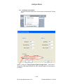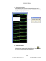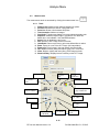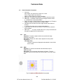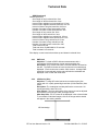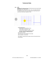
1
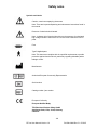
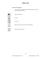
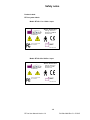
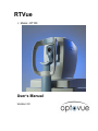
RTVue Model - RT100 User’s Manual Version 2.0 Publishing details RTVue Version 2.0 Optovue Inc. Fremont, CA 94538 Phone: 510-623-8868 Fax: 510-623-8668 www.optovue.com e-mail: [email protected] For Customer Service or Technical Support: (510)623-8868 Revision Control Part Number Rev Software ver. 500-42929 B v 2.0.3.2 Description Release Date 7/24/2007 License and use of the RTVue-100 systems is intended only for trained medical personnel in accordance with the license agreement – all other usage is prohibited – warranty restrictions and possible claim limitations apply. Contents 1 SAFETY NOTES ......................................................................................................... 1-1 2 INSTRUMENT DESCRIPTION ................................................................................ 2-1 2.1 3 RTVUE SYSTEM CONFIGURATION: ....................................................................... 2-1 GETTING STARTED ................................................................................................. 3-3 3.1 UNPACKING THE RTVUE SYSTEM:........................................................................ 3-3 3.1.1 Step1: Inspect the shipment ............................................................................. 3-3 3.1.2 Step2: Remove the cover and enclosure .......................................................... 3-3 3.1.3 Step3: Remove Scanner, Computer and Monitor............................................. 3-4 3.1.4 Step 4: Unpack Scanner, Computer and Monitor............................................ 3-4 3.2 SETTING UP THE SYSTEM: ...................................................................................... 3-5 3.2.1 Setting up the LCD monitor, Arm and PC ....................................................... 3-5 3.2.2 Setting up the OCT scanner ............................................................................. 3-6 3.2.3 Unlock the RTVue Scanner .............................................................................. 3-8 3.2.4 Powering up the system ................................................................................... 3-9 3.3 TEST SYSTEM CONTROLS ...................................................................................... 3-9 4 PATIENT MENU......................................................................................................... 4-1 4.1 4.2 4.3 4.4 4.5 4.6 4.7 5 PATIENT LIST: ....................................................................................................... 4-1 NEW PATIENT:....................................................................................................... 4-2 PATIENT INFORMATION:........................................................................................ 4-2 NEW VISIT............................................................................................................. 4-3 CHANGE DATE OF BIRTH FORMAT ........................................................................ 4-3 EDITING PATIENT OR VISIT INFORMATION ............................................................ 4-3 PATIENT LIST SHORT-CUTS ................................................................................... 4-4 EXAMINE MENU ....................................................................................................... 5-1 5.1 ACQUIRING OCT IMAGES: .................................................................................... 5-1 5.2 SCAN PATTERNS ORGANIZATION ........................................................................... 5-2 5.3 SELECTING A PATIENT TO BE EXAMINED: .............................................................. 5-3 5.4 SCAN LIST:............................................................................................................ 5-3 5.5 (SCAN) PROTOCOL: ............................................................................................... 5-5 5.6 COPY VISIT ............................................................................................................ 5-6 5.7 SCANNER CONTROL TABS ..................................................................................... 5-6 5.8 CLINICAL TAB CONTROLS:.................................................................................... 5-7 5.9 ADVANCED TAB CONTROLS:................................................................................. 5-8 5.10 PROCESS AVERAGE ............................................................................................... 5-9 5.11 SET IMAGE CONTROL DEFAULT ........................................................................... 5-11 5.12 REVIEWING SCAN IMAGES: ................................................................................. 5-12 5.13 SAVING SCAN IMAGES: ....................................................................................... 5-12 5.14 CORRECT ALIGNMENT OF LIVE OCT IMAGE ........................................................ 5-13 Example of NHM4 scan images location ..................................................................... 5-13 6 ANALYZE MENU..................................................................................................... 6-14 6.1 ANALYZE LAYOUT .............................................................................................. 6-14 6.1.1 OCT Image Selection ..................................................................................... 6-15 6.1.2 Analyze List.................................................................................................... 6-15 6.1.3 Diagnosis Field.............................................................................................. 6-15 6.2 MEASUREMENT ................................................................................................... 6-16 6.2.1 Tools: ............................................................................................................. 6-16 6.2.2 Manual Measurement .................................................................................... 6-17 RTVue User Manual PN 500-24034 Rev. B 11/2006 Contents Progressive/Asymmetry Comparison: ........................................................... 6-18 6.2.3 6.3 ANALYZE RESULT LAYOUT ................................................................................. 6-19 6.3.1 Line ................................................................................................................ 6-19 6.3.2 Cross Scan ..................................................................................................... 6-20 6.3.3 3D Macula Presentation................................................................................ 6-21 6.3.4 MM5 Analysis Presentation........................................................................... 6-22 6.3.5 MM5 Progressive Analysis Presentation....................................................... 6-24 6.3.6 MM6 Analysis Presentation........................................................................... 6-25 6.3.7 Missing scans Due to blink ............................................................................ 6-26 6.3.8 MM6 Progressive Analysis Presentation....................................................... 6-28 6.3.9 RNFL3.45 Analysis Presentation................................................................... 6-29 6.3.10 RNFL 3.45 Progressive Analysis Presentation ......................................... 6-30 6.3.11 NHM4 Analysis Presentation.................................................................... 6-31 6.3.12 3D Optic Disc Presentation ...................................................................... 6-40 6.3.13 Comparison............................................................................................... 6-41 6.3.14 MM7 Analysis Presentation ...................................................................... 6-43 7 FILE MANAGEMENT MENU .................................................................................. 7-1 7.1 7.2 7.3 7.4 7.5 7.6 7.7 7.8 8 MAINTENANCE & TROUBLESHOOTING........................................................... 8-1 8.1 8.2 9 ARCHIVE DATA ..................................................................................................... 7-1 RETRIEVE DATA .................................................................................................... 7-2 BACKUP ................................................................................................................ 7-3 RESTORE ............................................................................................................... 7-3 IMPORT (IMAGES).................................................................................................. 7-4 BATCH PROCESS.................................................................................................... 7-5 CLEAN DIAGNOSIS DATA: ..................................................................................... 7-5 DATABASE MANAGEMENT MENU ......................................................................... 7-6 ROUTINE CARE ...................................................................................................... 8-1 DATABASE MAINTENANCE.................................................................................... 8-2 SCAN PATTERN SPECIFICATIONS ...................................................................... 9-1 9.1 SCAN PATTERNS .................................................................................................... 9-1 9.2 SCAN ORIENTATION CONVENTION:....................................................................... 9-3 9.2.1 Line:................................................................................................................. 9-3 9.2.2 MM5................................................................................................................. 9-3 9.2.3 RNFL3.45 ........................................................................................................ 9-4 9.2.4 3D Macular (Disc)........................................................................................... 9-4 9.2.5 NHM4 .............................................................................................................. 9-5 9.2.6 MM7................................................................................................................. 9-6 10 USER PREFERENCE ............................................................................................... 10-7 11 TECHNICAL DATA ................................................................................................. 11-9 11.1 12 SYSTEM SPECIFICATION ...................................................................................... 11-9 APPENDIX ................................................................................................................. 12-1 12.1 PRINTER INSTALLATION ...................................................................................... 12-1 RTVue User Manual PN 500-24034 Rev. B 11/2006 Safety notes 1 Safety notes General This is instrument has been developed and tested in accordance with Optovue safety standards as well as national and international regulatory guidelines to ensure a high degree of instrument safety. Please observe all safety notes and information in this manual and on the device labels. This device does not produce any waste that needs disposal. Product contains no material which has a chemical hazard concern. Proper instrument use 1. Always enter patient information first. 2. Clean patient contact surface (forehead and chin rest according to the cleaning method in this manual). 3. Instantly turn off the power switch of the instrument and disconnect the power cable if uncertain problems arise. 4. Clean ocular lens frequently to ensure good image quality. 5. Adjust power table height properly to ensure patient comfort during the examination. 6. Align the patient’s head and eye position to the canthus indicator mark on the chin and forehead rest assembly. 7. Dim the room lights to allow natural dilation of the patients’ pupil and to provide a comfortable visualization of the fixation target without glare. Intended Use The RTVue is an optical coherence tomography system indicated for the in vivo imaging and measurement of the retina, retinal nerve fiber layer, and optic disc as an aid in the diagnosis and management of retinal diseases. Note: The RTVue OCT is not intended to be used as the sole diagnostic aid in disease identification of classification. Warning: User Changes to Software or Hardware The RTVue is a medical device. The software and hardware has been designed in accordance with U.S., European and other international medical device design and manufacturing standards. Unauthorized modification of the RTVue software or hardware, or any addition or deletion of any application in any way can jeopardize the safety of operators and patients, the performance of the instrument, and the integrity of patient data. ANY CHANGES, ADDITIONS OR DELETIONS TO APPLICATIONS, OPERATING SYSTEM, OR MODIFICATION TO HARDWARE IN ANY MANNER OR FORM VOIDS THE WARRANTY COMPLETELY. 1-1 RTVue User Manual Version 2.0 PN 500-42929 Rev. B 07/2007 Safety notes Warning: Phototoxicity Because prolonged intense light exposure can damage the retina, the use of the device for ocular examination should not be unnecessarily prolonged, and the brightness setting should not exceed what is needed to provide clear visualization of the target structures. The retinal exposure dose for a photochemical hazard is a product of the radiance and the exposure time. If the value of radiance were reduced in half, twice the time would be needed to reach the maximum exposure limit. “While no acute optical radiation hazards have been identified for direct or indirect ophthalmoscopes, it is recommended that the intensity of light directed into the patient’s eye be limited to the minimum level which is necessary for diagnosis. Infants, aphakes and persons with diseased eyes will be at greater risk. The risk may also be increased if the person being examined has had any exposure to the same instrument or any other ophthalmic instrument using a visible light source during the previous 24 hours. This will apply particularly if the eye has been exposed to retinal photography.” Caution: Federal law restricts this device to sale by or on the order of a Physician or Practitioner (CFR 801.109(b)(1)). Product Compliance 93/42/EEC Medical Device Directive Electromagnetic Compatibility (EMC) : EN 60601-1-2:2001 The RTVue100 device has been tested to comply with the emission and Immunity requirements of EN60601-1-2:2001. The RTVue100 is intended for use in an electromagnetic environment where radiated RF disturbances are not beyond the standard defined in EN60601-1-2:2001. CB Certification: under IEC 60601-1 1-2 RTVue User Manual Version 2.0 PN 500-42929 Rev. B 07/2007 Safety notes Symbols and Labels Caution, consult accompanying documents. Note: There are important Operating and maintenance instructions found in the manual. Presence of electrical shock hazard. Note: Indicates risk of electrical shock due to the presence of uninsulated high voltage inside the instrument. Do not remove the instrument cover or parts. Fuse Type B Applied parts. Note: This instrument complies with the specified requirements to provide protection against electrical shock, particularly regarding allowable patient leakage current. Manufacturer Authorized European Community Representative Serial number Catalog number / part number European Conformity European Notified Body: TÜV Rheinland Product Safety GmbH Am Grauen Stein, Köln, 51105, Germany CE 00197 1-3 RTVue User Manual Version 2.0 PN 500-42929 Rev. B 07/2007 Safety notes Protective Packing Symbols The protective packing symbols specify the handling requirements and the transport and storage conditions. Fragile, Handle with care Keep Dry This end up Relative Humidity (10% to 100%, including condensation) Temperature (-40 to 70 deg. C) 1-4 RTVue User Manual Version 2.0 PN 500-42929 Rev. B 07/2007 Safety notes Product Labels: RTVue system labels: Model: RT100-1 for 110Va.c input Model: RTVue100-1 41752 Christy Street Fremont CA 94538 USA Voltage: 120 V A.C. Frequency: 50/60 Hz Current: 6 A 0197 Tested to comply with FCC standard 2007 P/N: 500-43070 Model: RT100-2 for 230V a.c input Model: RTVue100-2 41752 Christy Street Fremont CA 94538 USA Voltage: 230 V A.C. Frequency: 50 Hz Current: 3 A 0197 Tested to comply with FCC standard 2007 P/N: 500-43067 1-5 RTVue User Manual Version 2.0 PN 500-42929 Rev. B 07/2007 Safety notes RT Scanner Label: (common for both RT100-1 and RT100-2 models) System PC Label: Model: RTVue PC 41752 Christy Street Fremont CA 94538 USA Voltage: 115/230 V A.C. Frequency: 50/60 Hz Current: 6.3 A 0197 Tested to comply with FCC standard 2007 P/N: 500-43074 1-6 RTVue User Manual Version 2.0 PN 500-42929 Rev. B 07/2007 Instrument Description 2 Instrument Description What is the RTVue system? The RTVue is a Fourier Domain OCT system that can non-invasively make images of retinal tissue in-vivo, with high acquisition speed and high-resolution scans. The first generation OCT system developed in early 1990s was a Time-Domain system, which relied on the mechanical scan method to obtain the tissue depth signal. The scan speed is limited to 400 A-scan per second in conventional timedomain OCT due to the mechanic motion barrier. The RTVue uses a camera to acquire the A-scan signals simultaneously without mechanical motion. The RTVue system’s scan speed is 26,000+ A-scan per second, or 65 times faster than the conventional OCT system. Due to the increase in scan rate, artifacts in OCT images caused by eye motion are eliminated in most* scan designs. (*3D scans with nearly 52,000 A-scans take 2 seconds to acquire. Motion artifacts may be present.) The RTVue system also employs a high bandwidth light source; the tissue resolution is about 4 - 5 micrometer, double that of a conventional OCT system. With such an improvement in speed and resolution, RTVue provides a much more reliable and detailed retinal and nerve head map, with metrics in a much shorter period of time. 2.1 RTVue System Configuration: The RTVue system is shipped in one paletted box, which contains the following hardware: 1. RTVue Scanner: This is the main component of the RTVue system. It is used to view and scan the patient’s retina, collect the OCT signal, and send it to the computer for processing. It also provides a fixation light target on which the patient can fixate during the scan, as well as a position sensor for automatic detection of whether the left or right eye is aligned for scanning. Communication between the scanner and computer is achieved via a USB cable connection. The RTVue uses a medical-grade power supply. 2. Computer: The computer is used to control the scanner during the patient examination. The application software provides data analysis, presentation, and data storage and archiving. A relational database is included to organize all patient information and data, as well as to allow for search capability. 3. System Table: The system table provides power to the RTVue scanner, computer, and computer display through a medical-grade isolation transformer to prevent 2-1 RTVue User Manual Version 2.0 PN 500-42929 Rev. B 07/2007 Instrument Description leakage current from main AC power. The table elevation can be adjusted to fit patient height. The telescopic lift that supplies the power of the RTVue system is medical grade. 4. Monitor (Computer Display): A 17” LCD flat panel display for graphic user interface and data presentation. 5. Keyboard and Mouse System Configuration: Model: RT100-1: 110V AC. Model: RT100-2: 230V AC. Monitor Power switch RTVue Scanner & Label Printer (optional) Up/Down switch Keyboard & Mouse Computer RTVue Label & serial number Power reset button System Table A.C. Power Plug 2-2 RTVue User Manual Version 2.0 PN 500-42929 Rev. B 07/2007 2-2 RTVue User Manual Version 2.0 PN 500-42929 Rev. B 07/2007 2-3 RTVue User Manual Version 2.0 PN 500-42929 Rev. B 07/2007 3 Getting Started 3.1 Unpacking the RTVue System: Crate contains the following items. 1. 2. 3. 4. 5. 6. 7. 8. RTVue Scanner Power Table Computer monitor Computer system Monitor Holder Keyboard Mouse Accessory Box 3-4 RTVue User Manual Version 2.0 PN 500-42929 Rev. B 07/2007 3.1.1 Step1: Inspect the shipment The instrument is shipped in a single crate. Check for any damage to the package. 3-5 RTVue User Manual Version 2.0 PN 500-42929 Rev. B 07/2007 3.1.2 Step2: Remove the cover and enclosure Monitor 3-6 RTVue User Manual Version 2.0 PN 500-42929 Rev. B 07/2007 Computer Scanner Power Table 3.1.3 Step3: Remove Scanner, Computer and Monitor First remove the scanner, computer, and monitor, followed by the power table from the crate. 3-7 RTVue User Manual Version 2.0 PN 500-42929 Rev. B 07/2007 Remove power table from the crate 3-8 RTVue User Manual Version 2.0 PN 500-42929 Rev. B 07/2007 3.1.4 Step 4: Unpack Scanner, Computer and Monitor Remove all packing material and then carefully lift the scanner from the scanner box. Note: Lift the scanner from the bottom of the scanner. DO NOT grab the patient head rest. The scanner weighs 61 lb (27 kg), so it is recommended to have two people hold on to each side. Refer to the manufacturer manuals to unpack computer and monitor. Before removal After removal 3-9 RTVue User Manual Version 2.0 PN 500-42929 Rev. B 07/2007 3.2 Setting up the system: Caution: Equipment assembling must be done by trained personnel only 3.2.1 Setting up the LCD monitor, Arm and PC 1. Mount the monitor holder arm onto the table top and secure with the washer and nut provided. 2. Connect the LCD monitor to the top section of the mounting arm assembly with the four screws provided. 3. Place fiber washer over the support post and place the top section (connected to the LCD) on to the support post. Secure hex screws. 4. Secure the monitor cables to the arm with clips and drop the power and VGA cables through the tabletop opening. 3-10 RTVue User Manual Version 2.0 PN 500-42929 Rev. B 07/2007 5. Install the computer and connect the computer as shown in the image 3-11 RTVue User Manual Version 2.0 PN 500-42929 Rev. B 07/2007 6. Secure the computer to computer holder by link a steel wire from computer case to computer holder. Use screw to tighten the wire to both ends as shown in the picture. 7. Replace the back panel of the system. Caution: Use screw to secure the back panel cover for safety 3-12 RTVue User Manual Version 2.0 PN 500-42929 Rev. B 07/2007 3-13 RTVue User Manual Version 2.0 PN 500-42929 Rev. B 07/2007 Connect cables for computer 3.2.2 Setting up the OCT scanner 1. Hold the scanner by the bottom only and lift onto the table. Caution: The OCT scanner weighs 61 pounds, and the x-y scanner head may move around, causing the scanner to tip over. 2. Set scanner head carefully into the four foot holes. Remove the hex screw and open the cable connection cover on the underside of the table top. 3-14 RTVue User Manual Version 2.0 PN 500-42929 Rev. B 07/2007 Correct way to hold the scanner unit 3-15 RTVue User Manual Version 2.0 PN 500-42929 Rev. B 07/2007 Open the cover for scanner cables 3. Connect the wires as shown in the picture. 4. Replace base cable cover. 3-16 RTVue User Manual Version 2.0 PN 500-42929 Rev. B 07/2007 Connect cables for scanner Caution: Use screw to secure the base cover for safety. 3-17 RTVue User Manual Version 2.0 PN 500-42929 Rev. B 07/2007 Caution: The power cord is the only way to disconnect the scanner from the power source. To emergency power-off the system, unplug the power cord from the wall or from the system immediately. 3.2.3 Unlock the RTVue Scanner 1. Use a fingernail or small flat screwdriver and remove the cap on the right side of the joystick. 2. Unscrew the lock until the screw ‘lifts up” (do not try to remove). 3. Replace the caps. 3-18 RTVue User Manual Version 2.0 PN 500-42929 Rev. B 07/2007 3.2.4 Powering up the system 1. Plug the power cord into the wall to power up the table. 2. Turn the main power switch on the table to ON (down) to power up the scanner, monitor, and computer. 3. Turn on the power button on the monitor. 4. Press the computer power button to boot up the system. 5. Double click the RTVue icon to start RTVue. If no icon is available, click the <Start> button located on the bottom-left of the screen. When the menu pops up, select Program, then click on RTVue to start running the program. 6. The main page of the application software will start. 3.3 Test System Controls 1. 2. 3. 4. Unscrew the X-Y scanner anchoring head screws. Table up and down control. Chin rest up and down control. Chin rest up and down limit indicators (yellow light on). 3-19 RTVue User Manual Version 2.0 PN 500-42929 Rev. B 07/2007 5. Stop scan button (on top of the joystick) 3-20 RTVue User Manual Version 2.0 PN 500-42929 Rev. B 07/2007 Patient Menu 4 Patient Menu The patient menu contains three components: 1. Patient List 2. Patient Information 3. Visit Information In the patient menu, the user can search, add, and edit patient information. It is designed to help you schedule a patient’s visit in advance, preview today’s or this week’s scheduled patients, and search for a patient’s history. 4.1 Patient List: The patient list displays the results of the user-defined search criteria. 1. 2. 3. 4. All Patients Current Patient This week Today The patient list display can be filtered by following criteria: 1. Physicians name 2. Disease 3. Scan protocol You may sort the results by: 1. Patient Name 2. Last Visit Time You may search for a specific text string: 1. 2. 3. 4. EMR ID Name (first or last) Last Name only First Name only 1. Type the patient’s EMR ID, Name, or Last/First Name in the [Search By] space and click on the designated button; this will move the searched patient to the top of the list. 2. Clicking on the patient’s name will list all the patient’s visits and will open the patient’s information. 3. Clicking on the visit will open the visit information. 4-1 RTVue User Manual Version 2.0 PN 500-42929 Rev. B 07/2007 Patient Menu 4.2 4.3 New Patient: To create a new patient, click the [New Patient] button, fill out the information fields (fields marked with a “*” are required – if the Refraction is “0” diopters [spherical equivalent] then leave blank), and click the [Save] button at the very bottom of the window. If you would like to cancel this operation, then simply click on [Cancel] button to exit the New Patient screen. Patient Information: The patient information is shown when a patient is selected. 1. Required information fields are marked by an “ * ”. 2. Refraction value (at the time patient is being examined) is used to set the initial focus for scanner. The focus (scan beam and video fundus image) can be further adjusted in the Clinical Tab, before or during a scan. 3. Disease Category is a user defined list of diseases. The disease category (multiple choices) can be used as a patient list filter. 4. Diseases can be entered one at a time by clicking the [add new] button 5. The selected Patient Name, DOB, and EMR ID are always shown on the title bar of the Report window. 6. If the [Save] button is grayed-out, check to see that all required fields are filled. 4-2 RTVue User Manual Version 2.0 PN 500-42929 Rev. B 07/2007 Patient Menu 4.4 4.5 New Visit To create a new visit, click the [New Visit] button, fill out the information fields, and click the [save] button. If you would like to cancel this operation, then simply click the [cancel] button to exit the New Visit screen. Change Date of Birth Format The preferred format of date of birth can be selected in the user preference: 4.6 Editing Patient or Visit Information To edit a patient’s information, select the patient name and click the [Edit] button. To edit a patient’s visit information, select a visit time and click the [Edit] button. 4-3 RTVue User Manual Version 2.0 PN 500-42929 Rev. B 07/2007 Patient Menu Patient List Short-cuts 4.7 Click on the patient’s name to view patient visits. Right click on the patient name or visit date to view options: • • • Add New Visit – automatically create a new visit using the current date for the selected patient, which takes the system directly to the Examination screen. Delete Current Visit – Deletes the selected visit (any visit in the patient visit history) Delete Current Patient. - Deletes the selected patient (a warning message appears first to verify that this is the intended action). Click [OK] to confirm delete or [cancel] to withdraw the operation. 4-4 RTVue User Manual Version 2.0 PN 500-42929 Rev. B 07/2007 Patient Menu 4-5 RTVue User Manual Version 2.0 PN 500-42929 Rev. B 07/2007 Analyze Menu 5 Examine Menu 5.1 Acquiring OCT Images: The following is a general procedure to acquire OCT images: 1. 2. 3. 4. 5. 6. 7. 8. 9. 10. 11. 12. 13. 14. 15. Select an Existing Patient or Create a New Patient. Select a visit or create a new visit. Click the Examine tab. Select desired scan patterns or scan protocol. Select the eye(s) to be scanned. Click ADD. Double click or highlight the scan name, then click on the SCAN button at bottom center (this will activate the scanning process). Align patient pupil with center of scan and move through pupil Adjust to get best fundus IR image (view of fundus from edge to edge – there may be dark areas on either side when imaging the optic disc). Hold scanner head still and adjust Z-motor if necessary a. Double clicking in the scan window (same as Z Auto button) will bring scan to the window OR b. If scan is visible in the window, click once in the scan window and use mouse scroll wheel to bring scan to target area Adjust scan position in live IR image (if it is not where you wish it to be) by: a. Double clicking the mouse cursor in the center of where you want the scan to be done (IR image) OR b. Click and hold down on left mouse button with cursor on scan pattern, drag to desired location, and release the left mouse button. Adjust scan image quality using position (X/Y), Focus or P-Motor. Stop scan (by pressing the joystick button) – this is the capture function. Review OCT slices. Save the scan. 5-1 RTVue User Manual Version 2.0 PN 500-42929 Rev. B 07/2007 Analyze Menu 5.2 Scan patterns organization Scan patterns available are organized into two groups based on primary purpose: Retina and Glaucoma Retina Tab Glaucoma Tab 5-2 RTVue User Manual Version 2.0 PN 500-42929 Rev. B 07/2007 Analyze Menu 5.2.1 The Protocol tab includes standard protocols for Glaucoma Baseline, Glaucoma Follow up, and Retina. Any protocols created by the user since the initial installation of the RTVue will also appear in the list. Protocol Tab 5.3 Selecting a Patient to be examined: There are two ways to select a patient for examination: 1. Select Patient from Patient Menu and then click the <Examine> tab. 2. Use the <Search> tab in the Examine Menu. To exit the search window, click anywhere outside the window. 5.4 Scan List: The scan list shows the scans to be performed in the current visit. 1. Select the scan pattern from the upper window or a scan protocol (click on the <Exam Protocol> tab to bring up the scan protocol window). 2. Select OD, OS, or both. 3. Select how many times each set of scans will be performed. 4. Click the Add button to add the scans into the scan list. 5. Repeat steps 1 through 4 for another scan pattern.. 5-3 RTVue User Manual Version 2.0 PN 500-42929 Rev. B 07/2007 Analyze Menu 1). Select scan tt 2). Select OD, OS, or b th 3). Select number of times each scan will be 4). Click to add to Examine ToD Li t An empty green circle indicates that the scan has not been completed. A solid green circle indicates that the scan has been completed. 5-4 RTVue User Manual Version 2.0 PN 500-42929 Rev. B 07/2007 Analyze Menu 5.5 (Scan) Protocol: A scan Protocol is a pre-defined group of scan patterns that can be linked under a defined protocol name (i.e. Glaucoma Protocol or Retina Protocol) under the <Exam Protocol> tab. You can create a scan protocol, which will be added to the scan protocol list. The specific scan list will be saved as a scan protocol with the name you have chosen for later use. Save the list as a protocol by clicking the [Save List as Protocol] button and entering a name. The scan protocols can be found by clicking the [Exam Protocol] button and can be selected for use by clicking on the desired protocol in the list. All scans contained in the protocol will be displayed in the scan list along with any other scan choices before performing the scans. The Protocol Management menu allows the user to control the protocols visible in the <Exam Protocol> tab. Protocol Management Screen 5-5 RTVue User Manual Version 2.0 PN 500-42929 Rev. B 07/2007 Analyze Menu 5.6 Copy visit To repeat a scan list from a previous visit, the [copy visit] function can be used to copy a specific list of scans and scan pattern settings to the clip board, and then pasted to a new visit. Previous visit scan list 5.7 Copy to a new list Scanner Control Tabs The scanner controls are organized into two primary groups: Clinical and Advanced. The Clinical tab contains all of the controls that are needed in a normal clinical environment to obtain the optimum scan images. The Advanced tab holds controls for modifying the scan, the noise level (default is 3), and the appearance of the live IR image. NOTE: During scanning, any time that a new scan is initiated, the presentation will default to the Clinical tab. 5-6 RTVue User Manual Version 2.0 PN 500-42929 Rev. B 07/2007 Analyze Menu 5.8 Clinical Tab Controls: 1. Eye Color: Select dark or light according to patient iris color to optimize the illumination, brightness, and contrast settings for IR image. The individual Brightness and Contract adjustment are in the Advanced Tab. a. If neither eye color is selected, then the default settings are the average of the respective values of illumination, brightness, and contrast for the dark and light eye. 2. Illumination: Adjusts the IR illumination for the IR video image. Level is set by selecting Eye Color, but may be adjusted separately to attain best image. 3. Grey Scale /Color Scale: Toggles live OCT image in gray-scale or color. 4. Z Motor / Auto: position adjustment: Click on the OCT image window, then use thumb wheel on the mouse to adjust Z-position. Double clicking on the OCT image window will auto-search Z position. This is the same as clicking on the “Auto” button next to the Z Motor. 5. Focus adjustment: Use to focus OCT and video image resulting in a sharper image. 6. P Motor: Polarization adjustment to optimize the OCT image signal strength resulting in a clearer image. 7. Vitreoretinal / Chorioretinal: Setting are programmed based on scan design to enhance either the information above the RPE (Vitreoretinal), or the choroid and overall information (choroiretinal) 8. Fixation Control: Use to turn on preferred fixation light location for patient to focus on. There are five fixation blue lights. 9. Process Average: For the Line scan and Cross Line scan only, you have the option of averaging the multiple scans to achieve and final “averaged” image. This process is used to reduce the noise of the OCT image and provide a smoother result. Eye or operator motion may limit the number of frames that can be used in this process. Quick eye motion may also smear the OCT image and reduce the resolution. 5-7 RTVue User Manual Version 2.0 PN 500-42929 Rev. B 07/2007 Analyze Menu 5.9 Advanced Tab Controls: 1. OCT Image Noise: Adjusts the noise level of OCT for best visualization of retina tissue. 2. Scan Length: To adjust the scan length with the center of scan fixed. 3. Scan Width: To adjust the width of a raster scan. The number of raster scan lines will be equally spaced in the width of scan pattern selected. 4. Scan Angle: To rotate the scan around the center of the scan. Use slider to rotate the scan or click on the scan graphic in the IR window and use the mouse wheel to rotate the scan direction. 5. Video Brightness: Controls the brightness of the Video image only (not the OCT scan) 6. Video Contrast: Controls the amount of contrast or shading between areas in the Video Image only (not the OCT scan) 7. XY Offset: Arrow keys can be used to move the scan pattern around in the IR image. a. Scan Pattern may also be moved around the IR image by clicking and holding down the left mouse button on the scan graphic in the live video image and drag the scan pattern to desired location. b. Scan pattern can also be moved to the desired location in the IR image by double clicking the mouse cursor in the center of where you want the scan to be centered (recommended method). 5-8 RTVue User Manual Version 2.0 PN 500-42929 Rev. B 07/2007 Analyze Menu 5.10 Process Average To obtain the final averaged image in either the Line or Cross Line scans: 1. Move the rectangle(s) on or over the region of interest 2. Then click OK in the message box. The rectangles may be adjusted to any size in order to encompass the area of primary interest. You may repeat the “Process Average” function as many times as you wish using any of the scans as the averaging basis. 1. Click on any image from the individual scans at the left side of the screen to see it in the large window. Place the rectangle and click on the Process Average button. NOTE: Larger ROI coverage may sometimes produce better results, however increasing the box size also increases the processing time. 5-9 RTVue User Manual Version 2.0 PN 500-42929 Rev. B 07/2007 Analyze Menu Default ROI/Anchor region for averaging Result of averaging 5-10 RTVue User Manual Version 2.0 PN 500-42929 Rev. B 07/2007 Analyze Menu 5.11 Set Image control default The Scan Parameter Setting menu can be found by clicking the OCT Image menu. NOTE: Setting for “Image Quality Signal Strength Index” should not be changed by other than Research site users with prior approval from Optovue personnel. 5-11 RTVue User Manual Version 2.0 PN 500-42929 Rev. B 07/2007 Analyze Menu 5.12 Reviewing Scan Images: After stopping the scan, the window will automatically bring up a list of thumbnail images. Click on any thumbnail image to display that scan in the working window. The window can be closed with the MSWindows “Close” (X box) icon on the upper right hand corner. 5.13 Saving Scan Images: will After reviewing the image, pressing the [Save] (disc icon) button save the images. Pressing the scan button again without saving will discard the current scan images and will restart the same scan. 5-12 RTVue User Manual Version 2.0 PN 500-42929 Rev. B 07/2007 Analyze Menu 5.14 Correct Alignment of live OCT image In all scan patterns, you will see one or more pairs of parallel red dashed lines. Some scans may have as many as four “live scan” windows with the target zone parallel lines. In any scan, the optimum placement of the live scan is between the red dashed lines. If the lines are horizontal, the scan should be in the upper part of the target area. (3D disc scan will have some of the scan image fall below the lower line; this is OK) In the case of vertical red dashed lines (such as in the NHM4), the physiology targeted should be between the two parallel lines. (see below) If you select a different scan mode (Vitreoretinal or Chorioretinal) than the default setting, the location of the red dashed lines will shift to the top or the bottom of the screen, depending on where the default position is. Example of NHM4 scan images location 1. Place RPE tips between two vertical guide lines 2. Place circular scan between two horizontal guide lines Note: This guidance applies to all scan patterns 5-13 RTVue User Manual Version 2.0 PN 500-42929 Rev. B 07/2007 Analyze Menu 6 Analyze Menu 6.1 Analyze Layout Print Measurement Report Form Measurement tools and image enhancement tool Image viewing tool Analyze list Report form window (analyze report) 1. Report Form: The window shows the analyze result 2. Measurement: Activates the tools for manual measurement on the OCT images 3. Print: Prints the current report form window 6-14 RTVue User Manual Version 2.0 PN 500-42929 Rev. B 07/2007 Analyze Menu 6.1.1 OCT Image Selection Above the Measuring Tools, there is a drop-down menu labeled “Scans”. If the scan pattern performed had more than one image, the different scan images are available for viewing by selecting from the drop-down menu. 6.1.2 Analyze List After selecting the patient, a list of scan records will appear under the tool window. Click a particular scan pattern to show the results in the report window. NOTE: Depending on the type of scan, it will sometimes take 5 to 10 seconds for the to the measurement result to appear the first time the scan data is selected. (This is due to calculation time). After the first time, the calculated data is stored and subsequent viewing will open in less time. 6.1.3 Diagnosis Field At the bottom of the Report screen is a textbox labeled “Diagnosis”. Any text entered here will be saved automatically when you exit the Analyze menu, whether you move to another window or exit the application entirely. 6-15 RTVue User Manual Version 2.0 PN 500-42929 Rev. B 07/2007 Analyze Menu 6.2 Measurement The measurement tools are accessed by clicking the measurement icon. 6.2.1 1. 2. 3. 4. 5. 6. 7. 8. 9. 10. 11. 12. 13. 14. Tools: Distance tool: Measures the distance between two points. Area tool: Measures the area of a polygonal area. Point Line: Draws a line between two points. Text Annotation: Add text to images. Grey/Color: Toggles scan display from gray-scale and pseudo-color. Snapshot: Saves the Report Page in .jpg format. File name has default but is user editable. User defined destination Select: Click to deselect the tool in use. Pan: Moves the OCT image around in window. Undo/Redo: Return to previous or prior state before/after an action. Zoom: Zooms in or out of the OCT image. (No interpolation) Zoom to fit: Fits all scans in the scan pattern into the window. OCT noise: Increase (white) and reduce (gray) OCT noise level. Video: Brighten (white) and reset (Grey) video image contrast. Show boundary: Display/remove boundary on the OCT image. 2). Area tool 3). Point Line 1). Distance tool 4). Text Annotation 5). Grey/Color 6). Saves Report page in JPEG file 12). OCT Noise 13). Video 7). Select 14). Show b d 8). Pan 9). Undo/Redo 10). Zoom 11). Zoom to fit 6-16 RTVue User Manual Version 2.0 PN 500-42929 Rev. B 07/2007 Analyze Menu 6.2.2 Manual Measurement To make a manual measurement, first select the tool, then make the desired measurement on the selected OCT image. First, select an initial or “anchor” point, then proceed to the second endpoint (linear measurement or arrow) or the next in a series (area measurement). Right clicking on the measurement will show the properties of the tool. NOTE: • You can select the Snapshot Tool to export a .jpg of the Measurement report screen. • You may select the Print option to print a copy of the Measurement report screen. 6-17 RTVue User Manual Version 2.0 PN 500-42929 Rev. B 07/2007 Analyze Menu 6.2.3 Progressive/Asymmetry Comparison: If there are eligible scans available in the patient visit history, the related progressive and/or Asymmetry option will be available as shown in the following graphic. Click the button to activate the additional analysis. Click to list scans that may be used in comparison with current scan. In the comparison window, click the first line to exit comparison window. 6-18 RTVue User Manual Version 2.0 PN 500-42929 Rev. B 07/2007 Analyze Menu 6.3 Analyze Result Layout 6.3.1 Line If you used the Averaging option prior to saving the Line (or Cross Line) scan. Both the Average and last single B-scan image are saved and available for review in the Analyze view.for review Note: The HD Line and HD Cross Line do not have the average option. Click on the [Average] & [No Average] button to select which image will be displayed. 6-19 RTVue User Manual Version 2.0 PN 500-42929 Rev. B 07/2007 Analyze Menu 6.3.2 Cross Scan Show vertical and horizontal of the scan images and the fundus image. 6-20 RTVue User Manual Version 2.0 PN 500-42929 Rev. B 07/2007 Analyze Menu 6.3.3 3D Macula Presentation • Blue line: C-scan position (can be tilted by adjusting left side of slider). • Red line: Position of vertical B-scan. • Green line: Position of horizontal B-Scan. • 3D quadrant: show 3D perspective view. • C-Scan quadrant: show the SLO, C-scan or Sum of C-scan. • Brown line: Right click to show the draw disc option. • Sum(µm): You can determine the “depth” of the scan Sum presentation (microns) in the C-Scan window . Check or uncheck Sum box to change the presentation. • Clicking anywhere in the SLO image in the upper left will automatically section the 3D presentation and B-Scan slice to the corresponding cross section. 6-21 RTVue User Manual Version 2.0 PN 500-42929 Rev. B 07/2007 Analyze Menu 6.3.4 MM5 Analysis Presentation Macular thickness values and retinal cross sectional images can be seen by moving the mouse cursor around the macular color-coded map. The grid shows the MM5 scan pattern (scans indicated in white). The horizontal and vertical cross section image will be displayed corresponding to the red color highlighted scan lines. The thickness will also be displayed. • Full Retinal Thickness measured from VRI to IS/OS layer. • Outer Retinal Thickness measured from the IS/OS layer to the IPL • Inner Retinal Thickness measured from VRI to IPL. • The tracing lines (boundary curves), are viewed or hidden by deselecting the “Show Boundary Curves” check box. The thickness map is further organized and presented at the top right in four macular regions (Stereoscopic Altas of Macular Diseases diagnosis and treatment, J. Donald M. Gass, Mosby, 3rd edition, volume 1, P3). The Perifovea region is split further into inner and outer regions. Each annual ring region is further split into 12 sections. 6-22 RTVue User Manual Version 2.0 PN 500-42929 Rev. B 07/2007 Analyze Menu Using the RPE or ILM elevation maps show the height of the RPE or ILM relative to a reference plane. The reference plane is the best elliptical fit to the RPE boundary. The reference level can be user adjusted using the value field marked “Ref” above the log scale. • The RPE elevation map is a sensitive tool to show choroidbased pathology. 6-23 RTVue User Manual Version 2.0 PN 500-42929 Rev. B 07/2007 Analyze Menu 6.3.5 MM5 Progressive Analysis Presentation The MM5 progressive analysis shows the difference between two MM5 analyses. To speed up the comparison results, it is better to analyze each individual MM5 scan first before making comparisons. Note: In all analysis functions, the analysis data (boundaries, maps etc.) will be stored in a file for future use after first analysis so the result of future analyses comes much more quickly. 6-24 RTVue User Manual Version 2.0 PN 500-42929 Rev. B 07/2007 Analyze Menu 6.3.6 MM6 Analysis Presentation The MM6 (12 Radial scans) accomplishes the same function as the MM5 (34 grid scans), however with fewer data points; ~12,000 VS ~19,500 A-scans) The MM5 Grid pattern is more accurate with “tie” points and less interpolation that the radial pattern. Note: Only the MM5 is included in the Normative Database collection that is in process Display Slicer option: Toggles the display of the MM6 between the standard presentation and as Radial Slicer presentation, including all 12 scans Show Lines: This option toggles the map display between showing with or without scan reference lines. Map graphic without lines works well for case study presentations 6-25 RTVue User Manual Version 2.0 PN 500-42929 Rev. B 07/2007 Analyze Menu 6.3.7 Missing scans Due to blink With version 2.0, scans that were saved which included missing Bscans due to blinking or weak signal for any reason (eyelash obstruction, iris clipping, etc) are rendered with the missing scan(s) indicated in gray in stead of white (scan indicator lines). Note: This rule is valid for MM5 MM6 and MM7 scans. Up to 50% of the scans from these patterns can be missing, and the algorithm will still render a map. All missing scans (blank or scans not used) will be indicated in gray. More scans missing equates to more interpolation in the map values. Missing lines indicated in gray. Date in this area is interpolated based on the nearest adjacent complete scan data. 6-26 RTVue User Manual Version 2.0 PN 500-42929 Rev. B 07/2007 Analyze Menu MM6 Slicer (Option) Display Click once on any scan to display it in the larger window at the top right. Double click on any scan to go immediately to the measurement mode presentation. Note: The Radial Slicer and the Slicer report displays have been changed to fit all scans onto one screen. These scan patterns will also print to one page. 6-27 RTVue User Manual Version 2.0 PN 500-42929 Rev. B 07/2007 Analyze Menu 6.3.8 MM6 Progressive Analysis Presentation The MM6 progressive (Change) analysis shows the difference between two MM6 analyses. To speed up the comparison results, it is better to analyze each individual MM6 scan first before making comparisons. Note: The MM5, MM6 and MM7 all have a new layer presentation for the Outer Retinal. This selection will show the IPL to IS/OS layer of the map. 6-28 RTVue User Manual Version 2.0 PN 500-42929 Rev. B 07/2007 Analyze Menu 6.3.9 RNFL3.45 Analysis Presentation 6-29 RTVue User Manual Version 2.0 PN 500-42929 Rev. B 07/2007 Analyze Menu 6.3.10 RNFL 3.45 Progressive Analysis Presentation 6-30 RTVue User Manual Version 2.0 PN 500-42929 Rev. B 07/2007 Analyze Menu 6.3.11 NHM4 Analysis Presentation The NHM4 map includes several pieces of important disc morphology information: disc margin contour, cup contour, and RNFL thickness map from disc margin up to 2 mm radius from the center of disc. 6-31 RTVue User Manual Version 2.0 PN 500-42929 Rev. B 07/2007 Analyze Menu 6.3.11.1 TSNIT Histogram RNFL thickness profile in the NHM4 is the thickness of RNFL at a calculated 3.45mm diameter around the center of the disc. NOT THE CENTER OF THE SCAN *The thickness measurement is re-sampled relative to the disc center, not scan beam center, so the de-centering of the disc relative to the scan beam will not affect the measurement. NOTE: This is the weak point of the conventional Time-domain 3.45mm RNFL circular scan. The RNFL thickness measurement is sensitive to disc and scan centering alignment. 6.3.11.2 Stereometric analysis results are listed in the spread sheet as follows: Click on “+” to expand the list 6-32 RTVue User Manual Version 2.0 PN 500-42929 Rev. B 07/2007 Analyze Menu Definitions: Cup Line (150um above disk line) Rim Volume (cross sectional view). Area above cup line Nerve head volume (cross sectional view). White line shade area above disk line Disk Line Cup area (enclosed by green line) Average sectional RNFL thickness at 3.45mm diameter center around the disk Rim area (enclosed between red and green line) Disk area (enclosed by red line) 6-33 RTVue User Manual Version 2.0 PN 500-42929 Rev. B 07/2007 Analyze Menu 6.3.11.3 Optic Nerve Head Morphology The ONH analysis can be performed with either one of four disc border baseline modes: 1. 2. 3. 4. 3D Baseline: Disc drawing from 3D Optic Disc scan (Default) Video Baseline: Disc drawing from IR image (NHM4) OCT Baseline: No Baseline* No disc drawing or RPE tip setting is required * The “No Baseline” option removes any serial registration capability, and therefore removes the possibility of progression analysis 6.3.11.3.1 The default setting for which baseline guides the analysis is set in Tool Bar. 6-34 RTVue User Manual Version 2.0 PN 500-42929 Rev. B 07/2007 Analyze Menu 6.3.11.3.2 3D Baseline is the disc boundary that is drawn using the SLO image in the 3D Disc scan presentation. “Right click” the mouse cursor on the SLO image and selecting “Draw Disc”. Then position the cursor and click the left mouse button on points coinciding with the disc boundary. 6-35 RTVue User Manual Version 2.0 PN 500-42929 Rev. B 07/2007 Analyze Menu 6.3.11.3.3 You may also use the 3D presentation screens to precisely determine the optic disc boundary, by using the RPE endpoints visualized in the B-Scan (lower left) and A-Scan (upper right). Add – Adds an anchor point on the image for disc boundary. Click the SLO image to find the correct point (RPE tip) position, then click Add. Fit – Uses anchor points to draw the disc boundary to close contour. Clear – Clears any currently marked anchor points Save – Saves the resulting disc drawing as the baseline for the NHM4 Note: As you click on any position in the SLO image screen, the three perspective windows also change to reflect the location and cross section within the 3D presentation. 6-36 RTVue User Manual Version 2.0 PN 500-42929 Rev. B 07/2007 Analyze Menu 6.3.11.3.4 Video Baseline is the disc boundary drawn on the video (IR) disc image. Right mouse click to show this box The Video Baseline can be modified if the baseline has been changed or if a clinician determines that it should be drawn differently. The brightness and contrast adjustment on the video image help the operator better visualize the disc boundary. NOTE: It is a challenge to draw a disc margin with a disc which has atrophy. This normally occurs in patients with high myopia. Using the 3D SLO image to draw and verify the disc boundary is recommended 6-37 RTVue User Manual Version 2.0 PN 500-42929 Rev. B 07/2007 Analyze Menu 6.3.11.3.5 OCT Baseline The radial scans from the NHM4 pattern are presented in the left portion of the NHM4 report pages. The placement of the tips can be verified in this window. Adjustment is achieved by placing the mouse cursor on the small yellow circle, holding down on the left mouse button and dragging to where you feel is correct. Then release the mouse button. Use mouse to drag the RPE tips to a correct location Save the RPE tips to form OCT baseline after dragging all RPE tips to proper locations. The modified RPE tips can be saved as an OCT baseline. In this case, 24 RPE tips define the shape of the disc margin. The operator can reprocess the analysis with the OCT baseline by right clicking on the NHM4 map. NOTE: The cup is defined by the intersection points of the nerve head inner boundary and a parallel line, which is 150µm above the connecting line of the RPE tips. 6-38 RTVue User Manual Version 2.0 PN 500-42929 Rev. B 07/2007 Analyze Menu RNFL thickness profile is the thickness of RNFL at 3.45mm diameter around the center of the disc. The thickness measurement is re-sampled relative to the disc center, not scan beam center, so the decentering of the disc relative to the scan beam will not affect the measurement. You can change the NHM4 mode according to your preference of where you want to draw the disc shape baseline. The “No Baseline” selection does not require the user to set RPE endpoints or draw the disc shape. NOTE: This selection does not allow serial registration of data for progression analysis. The “No Baseline” selection will provide no information on the Disc and Cup. It will only have RNFL information. 6-39 RTVue User Manual Version 2.0 PN 500-42929 Rev. B 07/2007 Analyze Menu 6.3.12 3D Optic Disc Presentation 6-40 RTVue User Manual Version 2.0 PN 500-42929 Rev. B 07/2007 Analyze Menu 6.3.13 Comparison Image comparison is a very handy tool used to see the difference of the retina between two visits. This option is available on all scan patterns. To use image comparison, first select the patient scan in the analyze window. If there are examinations available for comparison, the [Comparison] button will be available. This is the same method used to select progressive and asymmetry option. Progressive/Asymmetry/Image Comparison options 6-41 RTVue User Manual Version 2.0 PN 500-42929 Rev. B 07/2007 Analyze Menu (Comparison continued) Two rows of images will appear. You can select which frame image to compare by using the slider on the fundus image (SLO image in 3D scan) to choose the images on each visit. The horizontal and vertical image locations are indicated by horizontal and vertical highlight lines on the SLO image. The C-scan image plane is indicated by the horizontal line (tilt adjustable) on the horizontal image. The images to be displayed are independently adjustable for each visit. If the images from each visit are registered on the SLO image and the horizontal B-scan image, the adjustment bar will lock both visit images together and allow side by side comparison. A similar image comparison layout is available for all other scans (except for RNFL3.45 and NHM4 scans). Lines to register cscan plane Lines to register the horizontal and vertical image frames Image fly through bars 6-42 RTVue User Manual Version 2.0 PN 500-42929 Rev. B 07/2007 Analyze Menu 6.3.14 MM7 Analysis Presentation The thickness map shows the Inner Retinal thickness by default. Display may be changed based on user selection in the “Map Output.” The vertical cross sectional scan is displayed on the left side when moving the cursor in the thickness map. Above the thickness map there is a thickness difference map between superior and inferior retina defined by the red horizontal line. A target cursor in the difference map is synchronized with the cursor position in the lower thickness map. Both thickness value and thickness difference (superior thickness minus inferior thickness) appear on top of the difference map. Note: Data in the white area is not used for any calculation. 6-43 RTVue User Manual Version 2.0 PN 500-42929 Rev. B 07/2007 File Management Menu 7 File Management Menu 7.1 Archive Data To archive patient data into IOMEGA removable hard disk, first insert a HD disk and select the archive in the file menu. Archived patients will still appear on the patient list; however, to analyze the patient’s data, the same HD disk must be inserted to retrieve the patient’s data. The basic archive unit is the visit. Check the visit date on the patient to be archived. Use the sorting functions to help organize the patient list. After selecting the visits, follow the software instructions to archive the data. The disk should be labeled exactly the same as the label name entered in the software. It is advisable to make an extra copy of the archived disk in the event that the original disk is accidentally damaged or lost. 7-1 RTVue User Manual Version 2.0 PN 500-42929 Rev. B 07/2007 File Management Menu 7.2 Retrieve Data The archived patient visit will be indicated by the letter “a” appearing next to the scan information To retrieve a patient visit, select Retrieve from file menu. The retrieve data window will list all archived patients and the media label in which the data is stored. Follow the software prompts to retrieve the desired patient visit data. 7-2 RTVue User Manual Version 2.0 PN 500-42929 Rev. B 07/2007 File Management Menu 7.3 Backup The RTVue software performs backup automatically, but this process can also be done manually. The system automatically writes data into both the C: and D: drives when the data is saved in the system. The “patient information” database is automatically saved when the RTVue application software is closed. Manual backup and restore can be performed by clicking the BackupRestore.exe program on the desktop. 7.4 Restore Restoring data is usually only required if the data in the C: drive has been corrupted or accidentally deleted. The Restore function is used to copy the backup data from the D: drive to the C: drive. The Restore function can be initiated by clicking BackupRestore.exe on the desktop. 7-3 RTVue User Manual Version 2.0 PN 500-42929 Rev. B 07/2007 File Management Menu 7.5 Import (Images) The Import Image function allows the importing/transfer of fundus images from any location or device into the patient visit/scan file. First select patient/visit then, click on File > Import > Import Image. Select image in the network or from removable media (file types compatible are listed), and click Open. Image will be opened in a window for identification. Select eye [OD/OS], then image type and then Save file. You may import each type of image for the same scan. 7-4 RTVue User Manual Version 2.0 PN 500-42929 Rev. B 07/2007 File Management Menu 7.6 Batch Process This option can be run if you have not opened patient’s scans in the Analyze view and wish to pre-process all date. This will reduce the time required when scans are selected in the Analyze view. If there are new algorithms supplied from Optovue for particular scan patterns, you would first “Clean Diagnosis Data” (see next topic), and then run the patch process on All Patients It is best to use the Batch Process function whenever the system is not in use. Processing time is based on the number of patient and scans. 7.7 Clean Diagnosis Data: This process removes any previous calculations on the raw data. When opening a patient visit and scan in the Analyze view, the raw data will be processed again. This can also be used prior to reprocessing with updates, alternative or custom (research sites) algorithms. 7-5 RTVue User Manual Version 2.0 PN 500-42929 Rev. B 07/2007 File Management Menu 7.8 Database Management Menu In the Database Management drop-down menu, you may edit and determine the various fields and scans that are displayed in each category. • • • • Protocol – These can be created or modified per user preferences. Physician – Add a new physician, edit the name or other information of a current physician or delete a physician if not used by users. Operator – Add a new operator, edit the name or other information of a current operator or delete an operator if no longer exists. Disease –Add, delete or edit disease category 7-6 RTVue User Manual Version 2.0 PN 500-42929 Rev. B 07/2007 File Management Menu Protocol editor enables the user to modify the set protocols. 7-7 RTVue User Manual Version 2.0 PN 500-42929 Rev. B 07/2007 File Management Menu The Scan Pattern Management Screen allows the user to show or hide any of the scan patterns in the exam list. This allows the user to reduce the number of scan designs visible to only those that are used in the clinical site. 7-8 RTVue User Manual Version 2.0 PN 500-42929 Rev. B 07/2007 Maintenance & Troubleshooting 8 Maintenance & Troubleshooting 8.1 Routine Care 1. Dust Prevention: When not using the RTVue, make sure the cloth dust cover is placed over the unit. You can “Shut down” the PC at the end of each day. However, it is recommended that you leave the main power switch in the “ON” position. This helps keep the system at or near optimum operating temperature. 2. Ocular (Front Objective) Lens Cleaning: We recommended that the ocular (front objective) lens of the RTVue be cleaned daily. A weak OCT image or blurry video fundus image may be caused by an unclean front lens (eyelash, finger or nose prints, or excessive dust or dirt from the environment). Material required to clean front lens: 1) Diluted Acetone or Lens cleaning solution 2) Lens cleaning paper Method: Wet the lens paper with cleaning solution and wipe the ocular lens with one pass in one direction. Discard the used lens paper. Use a new sheet for each repeat cleaning until the lens is clean. 3. Head and Chin Rest Cleaning: The headrest pad and chin rest cup should be cleaned before every patient visit. Material required: 1) Disinfecting agent such as an anti-germicide or isopropyl alcohol; AND 2) Cloth or cleaning towels OR 3) Wet isopropyl alcohol cleaning paper pad Method: Soak the cleaning cloth or towel in disinfecting solution or use a wet isopropyl alcohol cleaning paper pad. Wipe the chin-rest cup and head rest pad. 8-1 RTVue User Manual Version 2.0 PN 500-42929 Rev. B 07/2007 Maintenance & Troubleshooting 8.2 Database Maintenance Database maintenance is designed to help with the preservation and restoration of the system database. It is a separate application from the RTVue system and cannot be accessed from within the RTVue Application. The two available actions are: Backup and Restore. BACKUP: Under the “File” menu heading, select “Backup” and a window will appear asking for the destination drive to which the database will be copied. The default drive is “D”; however, the destination drive can be changed simply by typing in the desired drive in the appropriate box. To begin the backup process, click the [Backup] button near the bottom of the window. NOTE: If your database is of a substantial size, it may take up to a few hours to complete. You might consider letting the backup sequence run overnight, as it is completely safe to leave the computer system on overnight. RESTORE: Under the “File” menu heading, select “Restore” to bring up a window asking for the destination drive to which the database will be restored. By default, the destination drive is “D”, but a different destination can be specified by typing in the appropriate box. When you are ready to begin database restoration, click the [Restore] button near the bottom of the window. 8-2 RTVue User Manual Version 2.0 PN 500-42929 Rev. B 07/2007 Technical Data 9 Scan Pattern Specifications 9.1 Scan Patterns Summary: Name Scan Pattern Line (0.039 seconds) Description Single line scan with speckle elimination process option Cross Scan (0.078 seconds) Cross line scan with speckle elimination process option HD Line (0.156 seconds) High definition single line scan HD Cross Scan (0.312 seconds) High definition cross line scan RNFL3.45 (0.15 seconds) Glaucoma Four 3.45mm diameter circular scans center on disc 3D Macular (2.2 seconds) 101 frames equally spaced B-scans to cover a square volume fixation at center # A-Scan 1 x 1024 (16 scans for 16,384 total data points averaged to single scan image) 2 x 1024 (8 scans in each direction are then averaged) 1 x 4096 (4 scans are captured – one is selected for saving) 2 x 4096 (8192 data points) 4 x 1024 Adjustability Default Transverse: 212mm (0.5 mm increment) Angle: 0 to 180o ( 1o increment) 6mm, 0 degree (from left to right of the monitor screen) Transverse: 212mm (0.5 mm increment) Angle: 0 to 180o ( 1o increment) Transverse: 212mm (0.5 mm increment) Angle: 0 to 180o ( 1o increment) Transverse: 212mm (0.5 mm increment) Angle: 0 to 180o ( 1o increment) Fixed 6mm, 0 degree (from left to right of the monitor screen) (4 scans are taken and presented. Avg is also presented in TSNIT) 101x512 (51,712 data points) Transverse: 3-8 mm (0.5 mm increment) Angle: 0 to 180o ( 1o increment) 6mm, 0 degree (from left to right of the monitor screen) 6mm, 0 degree (from left to right of the monitor screen) 3.45mm diameter. (From Temple to Superior to Nasal to Inferior (TSNI convention) 4mm x 4mm 9-1 RTVue User Manual Version 2.0 PN 500-42929 Rev. B 07/2007 Technical Data 3D Disc (2.2 seconds) Radial Slicer 101 frames equally spaced B-scans to cover a square volume fixation at 20o nasal 101x512 17 parallel line scans 17 x 512 (8704 data points) 12 x 1024 (0.34 seconds) MM6/Radial Slicer (0.27 seconds) MM5 (0.78 seconds) Retina MM7 (0.58 seconds) Glaucoma NHM4 (0.39 seconds) Glaucoma 12 radial line scans through a central point 11 horizontal lines with 5mm scan length and 0.5mm interval, 6 horizontal lines with 3mm scan length and 0.5mm interval, 11 vertical lines with 5mm scan length and 0.5mm interval, 6 vertical lines with 3mm scan length and 0.5mm interval, all centered at fovea (51,712 data points) 22x 668 + 12x400 Transverse: 3-8 mm (0.5 mm increment) Angle: 0 to 180o ( 1o increment) 2-10 mm in length 1-6 mm in width 4mm x 4mm L: 6mm W: 4mm 6mm scans at 6mm diameter circular pattern Fixed 5 x 5mm outer region. 3 x 3 mm inner region Fixed 7mm(H) x 7mm(V) (19,496 data points) 1 horizontal line with 7mm scan length, followed by 15 vertical lines with 7mm scan length and 0.5mm interval, centered 1mm temporal to fovea 1 x 467 /Horizontal line. 12 radial line scans 3.4mm length & 6 concentric rings (2.5-4.0mm diameter) All centered on disc 12x 452/line 3x587/ring (2.5, 2.8, 3.1mm) 3 x 775/ring (3.4, 3.7, 4.0mm) 15 x 400/Vertical line Fixed 9-2 RTVue User Manual Version 2.0 PN 500-42929 Rev. B 07/2007 Technical Data 9.2 Scan Orientation Convention: 1. Line scan: Zero degree: line scan from 9 o’clock to 3 o’clock. Plus (+) angle rotates line clockwise. Minus (-) angle rotates line counter clockwise. 2. MM5 scan: 17 (5mm) horizontal then 17 (5mm) vertical line scans 3. MM6 scan: 12 radial line scans (6mm) pivoting around the center a. Radial Slicer is the same as MM6 4. RNFL 3.45 scan: 4 circular scans at 3.45mm diameter from Temple to Superior to Nasal to Inferior back to Temple. (TSNI) 5. 3D Raster scan: A-scans from left to right, B-Scan from inferior to superior a. Slicer is the same using a vertical raster pattern) 6. NHM4 scan: First line from 6 O’clock to 12 O’clock, then rotate the lines clockwise. 7. MM7 scan: 15 (7mm) vertical scans and 1 (7mm) horizontal scan through the midpoint of the vertical scans. 9.2.1 Line: Objective: To acquire a high-resolution cross-sectional image anywhere in the retina. Description: Single--line 1024 A-scan captured 16 times (0.038 seconds ea.) After Stop Scan: The last 16 frames are displayed as thumbnails in the left side bar for review. 9.2.2 MM5 Objective: To measure the macular retinal thickness map for DME/CNV/CME. Description: 5x5 mm square grid centered on fixation. The grid spacing is 0.25 mm in the inner 3x3 mm area and 0.5 mm in the outer area. Fig 2. Illustration of Macular Grid 5x5 scan pattern 9-3 RTVue User Manual Version 2.0 PN 500-42929 Rev. B 07/2007 Technical Data (MM5 Continued) Detailed parameter: Scan length of long horizontal line: 5mm Scan length of short horizontal line: 3mm Interval of two neighbor long horizontal line: 0.5 mm Interval of two neighbor short horizontal line: 0.5 mm Interval of short to long horizontal line: 0.25 mm Number of a-scans in long horizontal line: 668 Number of a-scans in short horizontal line: 400 Scan length of long vertical line: 5mm Scan length of short vertical line: 3mm Interval of two neighbor long vertical line: 0.5 mm Interval of two neighbor short vertical line: 0.5 mm Interval of short to long vertical line: 0.25 mm Number of a-scans in long vertical line: 668 Number of a-scans in short vertical line: 400 Total a-scans=19,496 Total scan time=19,496/26000=0.75 seconds Total overhead: 0.03 seconds Pilot display: central cross-hairs and the top and bottom horizontal lines. 9.2.3 RNFL3.45 Objective: To obtain a RNFL thickness measurement with a conventional 3.45mm diameter circular scan around the disc. Description: Four circular scans with a 3.45mm diameter centered on the disc. The RNFL thickness of each circular scan is measured and displayed. Each circular scan contains 1024 A-scans. Average RNFL thickness of user-selected circular scans will also be calculated and displayed in the circular and linear chart. 9.2.4 3D Macular (Disc) Objective: To image 3D retinal structures at macular region (disc region) with 101 equally spaced high resolution (512A-scans/line) lines scans Description: The rectangular boundary defines the out area the 101 equally spaced line scan will cover. Scan Control: The size and location of the scan area can be adjusted and rotated by using length, width, and angle control. After Stop Scan: All 101 scans will be displayed in the review window. To see details of individual images, click on the image and the details will appear in the working window. 3D Scan design 9-4 RTVue User Manual Version 2.0 PN 500-42929 Rev. B 07/2007 Technical Data 9.2.5 NHM4 Objective: To measure the RNFL thickness and optic disc. Description: 24 radial lines with 3.4mm scan length followed by 6 concentric rings, all centered at the optic disc. Illustration of NHM4 scan pattern Detailed parameters: Circular scan diameters: 2.5, 2.8, 3.1, 3.4, 3.7, 4.0mm Meridian scan length: 3.4 mm Meridians: 0, 15, 30, 45, 60, 75, 90, 105, 120, 135, 150, 165 degree Number of a-scan in rings: 587 587 587 775 775 775 Number of a-scan in meridian scans: 452 Total a-scans=9510 Total scan time=9510/26000=0.37seconds Total overhead: 0.02 seconds Pilot display: centered cross-hairs (vertical and horizontal meridian scans) and the outermost circular scan (4.0 mm diameter) and inner most circular scan (2.8mm diameter) 9-5 RTVue User Manual Version 2.0 PN 500-42929 Rev. B 07/2007 Technical Data 9.2.6 MM7 Objective: To measure the inner retinal thickness map and total retinal thickness map for the glaucoma. Description: One horizontal line with a 7mm scan length followed by 15 vertical lines with a 6mm scan length and a 0.5mm interval, and centered one millimeter temporal to fovea. Fig 3. Illustration of Macular Raster7X7 scan pattern Detailed parameters: Scan length of horizontal line: 7mm Scan length of vertical line: 7mm Interval of two neighbor vertical line: 0.5 mm Number of a-scans in horizontal line: 934 Number of a-scans in vertical line: 800 Total a-scans=14,810 Total scan time=14,810/26000=0.57 seconds Total overhead: 0.01 seconds Pilot display: Cross-hair scan centered at fovea, right and left-most vertical scans. 9-6 RTVue User Manual Version 2.0 PN 500-42929 Rev. B 07/2007 Technical Data 10 User Preference User Preference can be found under Tools Menu. 1. 2. 3. 4. 5. 6. Date Format: allows you to choose different format for Date. Allow save eye blink data: select YES to save even if there are blinks, or NO to force a rescan when an eye blink is detected. Fixation LED Current (0-1000): adjust the blue LED output by increasing or decreasing the value Select RPE tips before savings scan: Select YES to draw RPE Tips before saving the scan, or select NO to draw them during the Analysis viewing. User Interface Setting: Controls the level of GUI complexity that is viewed. Default Scan Rates: Defaults can be changed as per the user’s preference. Click [OK] to save user preference changes. If [Cancel] is clicked, no changes will be saved. 10-7 RTVue User Manual Version 2.0 PN 500-42929 Rev. B 07/2007 Technical Data 10-8 RTVue User Manual Version 2.0 PN 500-42929 Rev. B 07/2007 Technical Data 11 Technical Data 11.1 System Specification A. RTVue Scanner: OCT Image Acquisition Rate: 26,000 A-scan/second Frame Rate: 256 to 1024 A-scan/Frame Optical Resolution: (in tissue) Depth: 5µm Beam Spot Size: 15µm Image Sampling Rate: Depth: 2.9µm Transverse: 8µm (nominal) Scan Range: Depth: 2 or 2.3mm Transverse: 2mm to 12mm Scan Beam Wavelength: λ=840±10nm, ∆λ (FWHW) = 50nm Exposure Power at pupil: 750µW B. Fundus Imager: FOV: 32o (H) x 22o (V) Monochrome CCD Camera: 768 x 498 pixel 1/3” CCD Format NIR Illumination: 735nm LED C. Patient Interface: Working Distance: 22mm Motorized Focus Range: -15D to +12D Internal Fixation: Center, ±3.5o (Horizontal), and ±18o (Horizontal) Motorized Chin-Rest adjustable range: 65mm Joystick controlled X-Y-Z adjustment: X-100m, Y-85mm, Z-25mm Lock-mechanism: Electro-magnetic activated D .Computer Unit: CPU> 3GHz Dual-Core Processor Primary Hard Disc Drive> 300GB (minimum or higher) Back up Hard Disc Drive> 300GB (minimum or higher) Archive DVD RW and Removable HD Disk RAM: 2 GB DAQ: Camera link frame grabber E. Display Unit: 17” Flat Panel LCD Monitor F. Power Table: Power Input: 110V a.c. (RTVue RT100-1) 230V a.c.(RTVue RT-100-2) Current: 1.8AMPS Frequency: 50/60 Hz Power Rating: 160W Maximum Force: 2500N Motorized adjustment range: 200 mm 11-9 RTVue User Manual Version 2.0 PN 500-42929 Rev. B 07/2007 Technical Data G. Circuit Breaker and Fuse: Thermal circuit breaker (main power entry) Rating: 6AMPs, 125-250VAC Dielectric Strength: 2500 VAC/1 minutes Operating Temp.: -10 oC to 60 oC Fuse (Power supply in Scanner) Rating: 4AMPs/250V Package: 5mm x20mm Type: Fast Acting, Short Time Lag H: Compliance: General Medical Medical System EMC of Medical System ITE (Computer) EN60601-1 EN60601-1-1 EN60601-1-2 EN60950 I: Environment: Operating Condition: (no condensation) Ambient Temperature: +10 to 40 oC Relative humidity: 30% to 75% Atmospheric pressure: 700 to 1060 mbar Storage and Transport Condition: Ambient Temperature: -40 to 70 oC Relative humidity: 10% to 100% (include condensation) Atmospheric pressure: 500 to 1060 mbar 11-10 RTVue User Manual Version 2.0 PN 500-42929 Rev. B 07/2007 Appendix 12 Appendix 12.1 Printer Installation WARNING: When powering a USB-interfaced printer to the RTVue system, it is recommended to connect the power through the designated power supply outlet in the PC compartment. This outlet is isolated from the wall plug (building power) through RTVue’s isolation transformer. If the printer is powered from somewhere other than the designated power outlet, the printer should be placed at least 1.5 meters away from the patient to avoid electric shock. 12-1 RTVue User Manual Version 2.0 PN 500-42929 Rev. B 07/2007