1
Atik Instruments 16/16HR user manual
Version 2.0 - December 2006
Page 1
1
2
Introduction............................................................................................................3
Pack Contents.........................................................................................................4
2.1
Pelican Case ...................................................................................................5
3
Atik Instruments 16/16HR.....................................................................................6
3.1
Camera Parts ..................................................................................................6
3.2
CCD ...............................................................................................................8
3.3
Analog to Digital Converter (ADC) ..............................................................8
3.4
Power Consumption.......................................................................................8
4
Ports .......................................................................................................................9
4.1
USB Port ........................................................................................................9
4.2
Auto Guiding Port..........................................................................................9
4.3
MiniDIN (Serial) Port ....................................................................................9
5
Thermal Stabilization.............................................................................................9
6
Additional Technical Information........................................................................10
7
Software Development Kit ..................................................................................11
8
Accessories ..........................................................................................................12
9
Artemis/ATK Capture..........................................................................................13
9.1
Features ........................................................................................................13
9.2
Using Artemis Capture ................................................................................14
9.3
Quick Start ...................................................................................................15
9.4
Main Screen .................................................................................................15
9.5
Exposure Settings Dialog.............................................................................16
9.6
Notes on the ATK-16 camera ......................................................................17
9.7
Display Options Dialog................................................................................17
9.8
Focus Assist .................................................................................................19
9.9
Colour cameras and the ArtemisRGB utility ...............................................20
9.10 Other controls...............................................................................................23
10
Maxim DL™ plug-in .......................................................................................24
11
AstroArt Plug-in...............................................................................................26
Page 2
1 Introduction
Atik Instruments Cameras represents today’s affordable and easy way to
achieve high quality images with a superior design. This version has new
redesigned hardware in order to answer the growing demand in fine quality
astrophotography cameras. A wide range of accessories is also available in
order to answer the needs of the most demanding astrophotographer.
The product you have purchased is a fine piece of hardware and will bring you
many moments of satisfaction, however, in order to maintain the product’s
quality any changes to the supplied camera and/or accessories without the
manufacturer’s written permission will void your warranty. Any further
development will be available to you through your local dealer or at www.atikinstruments.com.
Please take the time to read this document thoroughly in order to get the most
out of your Atik Instruments Camera. After doing so, get out there and
discover new worlds…
Page 3
2 Pack Contents
This pack includes:
•
•
•
•
•
•
•
•
1- Atik Instruments Camera 16
2- Pelican Case
3- CD-ROM with Software and manuals
4- USB Cable
5- Car lighter type power cable
6- Dust cover
7- 1.25” Nosepiece
8- Quick start guide
Page 4
2.1 Pelican Case
The Pelican Case is a high impact resistant case and is used to house your
camera and accessories in order to protect them from rough transportation.
By carrying the contents of this pack inside the provided case, Atik
Instruments assures you that practically nothing will damage your camera and
accessories. The inside foam prevents scratches on your camera as long as
accessories are not physically in touch with it. Please use the camera in the
proper part of the case with no accessories around it.
Note: To prevent accidents please always check that the Pelican case’s locks
are in fact locked.
Page 5
3 Atik Instruments 16/16HR
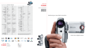
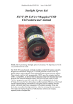
3.1 Camera Parts
•
•
•
•
•
•
•
1- Power socket
2- MiniDIN Port
3- Cooling Fan
4- Cooling Fan protector
5- CCD
6- Optical window
7- 1.25” Nosepiece
Page 6
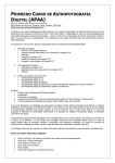
•
•
•
8 - Tripod Socket
9 - Auto Guiding Port
10- USB Port
Page 7
3.2 CCD
The used CCD in your camera depends on the model and on the fact if it’s a
color or black and white camera and also if it is a 16 or 16 HR model. Below is
a table showing the CCD used in all four options regarding these two models:
Black and White
Color
Atik Instruments 16(C)
SONY ICX429ALL
SONY ICX429AKL
Atik Instruments 16 HR(C)
SONY ICX285AL
SONY ICX285AQ
Due to the very clean nature of these CCD’s dark frames are in most cases
unnecessary. This is due to the low noise which stands at an amazing less
than 8 electron RMS.
The optical window used in front of the CCD is a BK7 with BBAR coatings on
both sides assuring that no reflection will appear in your image.
3.3 Analog to Digital Converter (ADC)
The Analog to Digital Converter (ADC) is a 16bit ADC. This means that your
Atik Instruments 16/16HR camera will allow you to record subtle levels of gray
providing you enhanced dynamic range when capturing an image.
3.4 Power Consumption
Your Atik Instruments camera was electrical and electronically designed in
order to have low power consumption so your autonomy is enhanced one step
further. Versatility is a very important feature since the 12V used by Atik
Instruments 16/16HR cameras can be plugged almost everywhere: e.g. car
battery or any other source which provides 12V. The less than 800mA that the
camera consumes in full operational status provides extended autonomy.
Page 8
4 Ports
4.1 USB Port
An USB 1.1 connection port is used in Atik Instruments cameras 16/16HR.
This might sound as a limitation but there is little importance in this fact.
Although Atik Instruments is aware that USB 2.0 is faster, USB 1.1 suffices if
you take certain facts into consideration. The first is that if you have to do
serious astrophotography you will note that 16 seconds – which is the time
needed to download the entire file in maximum resolution – is a very small
percentage of the time consumed in the field if you take into account the time
needed to set up the rest of your gear. Take setting up, focusing and a single
long exposure for instance. Having this summed up, if everything goes well –
really well – an hour is easily consumed. Now take that time and compare 16
seconds against it. On a per cent base this is 0.44% of that time –Not even
1%! -and taking this into account is it really that much? No.
4.2 Auto Guiding Port
Atik Instruments 16/16 HR cameras are compliant with this industry’s
demanding features. The auto guiding port enables you to do auto guiding
with any ST4 compatible guiding software when using the optional cable. See
accessories.
You will find this port schematic on section 6.
4.3 MiniDIN (Serial) Port
The MiniDIN port is a Serial Port following a proprietary protocol. This port will
be able to control several useful devices through this single port. Port
schematics are available on section 6.
5 Thermal Stabilization
Atik Instruments cameras are thermally stabilized in a way that your CCD will output
the best result that it can deliver. This information often appears with the indication
ΔT= -x where x in this case is 25. This means that the CCD’s temperature will drop
25º C below outside temperature. This is a thermoelectric process and therefore in
order to obtain the best results you should wait 1 to 2 minutes until thermal
stabilization is achieved. This fact also depends on the outside temperature so, higher
environment temperatures will demand more time for the CCD to stabilize. A fan is
also included and it is protected by the fan protector.
Page 9
6 Additional Technical Information
Sensor Type
Sony ExView
Sony ExView
Horizontal Resolution
752 pixels
1392 pixels
Vertical Resolution
582 pixels
1040 pixels
Pixel Size
8.6 uM x 8.3 uM
6.45 uM x 6.45 uM
ADC
16 bit
16 bit
Readout Noise
8 e-
6 e-
Interface
USB
USB
Power
12v DC 0.8A
12v DC 0.8A
Maximum Exposure Length
Unlimited
Unlimited
Minimum Exposure Length
1/1000 s
1/1000 s
Guide Port
ST-4 compatible
ST-4 compatible
Cooling
Thermoelectric
Thermoelectric
Weight
Approx. 500 g
Approx. 500 g
Pinouts for the external ports:
Autoguider port
Expansion Port
Distance from top of T-thread to focal plane:
Optical window thickness: 2mm
Page 10
Atik 16 - Aprox 15mm
Atik 16HR – Aprox 18mm
The following table refers to the angular resolution per pixel with certain focal
distances. The formula to calculate any other focal length not described is:
Pixel Size (mms) / Focal Distance (mms) * 206,3 = result in arc seconds/pixel (angular
resolution)
7 Software Development Kit
Due to the fact that our ever changing World is always finding new
applications for Atik Instruments cameras, a software development kit is
available at www.atik-instruments.com . This SDK is free of charge for now.
Page 11
8 Accessories
There are several accessories from Atik Instruments that will allow you to go
further into this never ending journey of discovering new worlds. These
include the following
•
•
•
•
•
•
IR Filter
Focal Reducer 0,5x
Manual Filter wheel
SLR Lens adapter for Nikon
SLR Lens adapter for Pentax S, K
SLR Lens adapter for Olympus
Other accessories will follow up very shortly, which will enhance even further
the joy of astrophotography.
Page 12
9 Artemis/ATK Capture
Artemis/ATK Capture is a standalone program which allows you to control
your Atik 16 camera, take images, preview them, and save them to standard
FITS files. It does not perform any image processing, other than simple
histogram manipulation for mapping the 16-bit images to the display.
The data saved in the FITS file is exactly what is read from the camera (raw),
so any adjustment is purely for display purposes.
Focus should be very easily achieved with focus assist as described further.
9.1 Features
The capabilities of Artemis/ATK Capture include:
· Control over exposure time, from 1milisecond (0,001s) upwards.
· Control over pixel binning.
· Selection of an image sub-frame for rapid focusing.
· Automatic capture of a series of images, saved with sequential file names.
· Adjustment of black and white levels, and log stretch for displaying images.
· Focus Assist option using data gathered from star images
· Zoom feature.
· Display adjusted for aspect ratio for sensor whose pixels aren’t square.
· Night-vision mode.
Page 13
9.2 Using Artemis Capture
The main Screen
When you first start the program, you will be warned if your Atik 16/16HR
camera is not connected or powered up. It is possible to run the program
without the camera by clicking on “ignore”, although most of the functions will
be unavailable.
The main settings in Artemis Capture are controlled using two dialogs, the
‘display options’ dialog and the ‘exposure settings’ dialog. Both of these are a
modeless dialog, which means that they can be left open while you run the
program and capture images, etc. However you should be aware that if one of
these dialogs is selected then certain keyboard shortcuts or mouse operations
in the main window may not behave as expected. If this happens, simply click
on the main window to select it.
Page 14
9.3 Quick Start
If you want to simply take a quick shot to verify that the program and camera
are working correctly, you can use the F1-F8 buttons to take a single test
image. F1-F4 take an exposure of 0.1, 1, 5 or 10 seconds respectively, and
F5-F8 use the same exposure times but binned at 2x2 for greater sensitivity.
Here’s a list of shortcuts:
F1: 0,1s
F2: 1s
F3: 5s
F4: 10s
F5: 0,1s (binned)
F6: 1s (binned)
F7: 5s (binned)
F8: 10s (binned)
The “Quick” menu
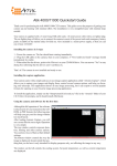
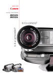
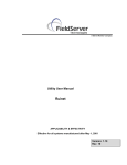
9.4 Main Screen
The main window in Artemis capture is used for displaying the most recently
captured image. A green outline rectangle is displayed in the window,
indicating the full size of the CCD sensor. If
a sub frame is being used for imaging then it
is indicated by a red outline rectangle within
the green one.
You can scroll the display using the
scrollbars, or by dragging it with the left
mouse button. Dragging the right mouse
button within the CCD area allows you to set
the sub-frame interactively. If you have a
mouse with a wheel, you can use the wheel
to zoom in and out - the point beneath the
mouse pointer is the ‘focus’ of the zoom, and
remains in the same place on the display.
Sub-Frame selection
Page 15
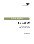
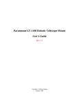
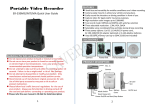
9.5 Exposure Settings Dialog
This dialog is displayed by selecting the ‘View |Exposure Settings’ menu
option, or by clicking the toolbar button. Here you are able to set the exposure
time for the image, the individual X and Y binning factors, and you can
numerically specify a sub-frame if you wish.
Also, a delay between exposures setting is available, since it is desirable to
have the auto guider stabilize before starting the next exposure. This can be
set in the “Delay(s)” box, and it’s measured in seconds.
If the Autosave box is checked then every
time an image is captured, it will automatically
be saved as a FITs file with a sequence
number appended to its name, in the form
C:\Artemis_001.fit.
Once you have selected the exposure
settings, you can take a shot using the
Camera |Snapshot’ menu option, or by
clicking the camera toolbar button. The
indicator at the bottom right of the window
shows the current camera status - exposure
time remaining, download state, etc.
Once the image is downloaded it will be
displayed on the main screen you can adjust
the display using the ‘Display Options’ dialog.
The Exposure dialog box
Page 16
9.6 Notes on the ATK-16 camera
If your camera is the ATK-16 model (not the “HR” model), the CCD sensor
is of the interlaced type normally used in video cameras (the Sony ICX429ALL). Because of this, an exposure with full vertical resolution (i.e. Y
binning = 1) has to be taken in two fields consisting of odd and even scan
lines respectively. These fields are then interleaved to produce the final
image.
Due to the time taken to download a field the exposure times of the two fields
may not match exactly, in which case some fine horizontal banding may be
visible in the image - this effect is reduced at longer exposure times, like 30s
and over. The effect is eliminated by stacking a few frames, which you will
have to do anyway if using exposures under 60s. For short exposures (less
than about 2.4s) the camera will take the two exposures consecutively rather
than simultaneously, only starting the second exposure after the first field has
been downloaded. In addition, with this type of CCD it is physically impossible
to produce true vertical binning at any odd multiple apart from 1. The Artemis
driver will simulate the correct binning behavior if such a binning multiple is
requested. To attenuate this effect, a “De-banding” filter is available in the
Exposure dialog box, which will cancel out most of it.
9.7 Display Options Dialog
This dialog is displayed using the ‘View |Display Options’ menu item, or by
clicking the toolbar button. It allows you to adjust the way in which the 16-bit
image is mapped to the PC’s display. In general, two values are chosen within
the range of 16 bit numbers present in the image. Pixel values equal to or less
than the lower value are displayed as black, and pixel values equal to or
greater then the higher value are displayed as white. Values in between are
displayed as shades of grey. The ‘Log’ value controls how the grey shades
are distributed – a value of zero produces a linear map, negative values
provide higher contrast at the higher end, and positive values boost the
contrast at the lower end.
The ‘Auto stretch’ box allows the program to automatically adjust the black
and white levels each time an image is captured. The levels are chosen such
that only a few pixels fall outside the range. If the box is unchecked then you
can manually adjust the black and white levels using the sliders.
The ‘Reticle’ checkbox will add a reticule to the displayed image. It may be of
use for determining the center of the frame, so that you can align your goto
telescope, for example. The ‘Negative’ checkbox will display the image as a
negative, which can be useful when trying to spot faint objects on a dark
background.
The ‘Correct aspect ratio’ box adjusts the displayed image according to the
physical dimensions of the pixels on the CCD sensor. If the box is checked
Page 17
then the height of the displayed image is scaled so that a square area on the
screen corresponds with a square area in the sky.
‘Night Vision’ changes the Windows colors to
shades of red, in order to help preserve visual
dark adaptation when using the program at
night. When the program shuts down, or the
box is unchecked, the original colors are
restored. [Hint: You can save the night vision
color scheme for use with other programs, if
you click the checkbox and then right-click the
Windows
desktop,
select
‘Properties
|Appearance’ and then ‘Save as’.
Give the scheme a name such as Night Vision
and you can then return to it any time you like
The Dialog box
using this dialog. You may also want to save
your standard color scheme, so that you can re-select it after using the Night
Vision scheme.]
Page 18
9.8 Focus Assist
When taking an astronomical image it is critical that focusing be as accurate
as possible. To help achieve this, Artemis Capture provides the Focus Assist
dialog.
When you have the camera roughly focused so that you can see stars in the
captured image, you can activate the focus assist dialog by double-clicking on
a star. For best results you need to choose one which is bright but not
overexposed, and which has a relatively clear area around it. The program will
select the brightest star in the vicinity of the selection, and draw a small box
around it. It will also pop up a dialog showing some information about the
Star’s image, in a large bold font so that you can read it when at the telescope
which may be some distance from the PC monitor.
The information provided is the star’s maximum brightness (the difference
between the brightest pixel and the background level), and the width of the
star image. This is calculated as the size of a square, centered on the star’s
centroid, containing half the total flux from the star. The objective is to adjust
the telescope’s focus until the
brightness reaches a maximum
and the width reaches a
minimum - this will give the
sharpest and brightest star
images.
Whilst focusing it is also a good
idea to select a sub frame
around the star in order to
reduce the image download
time, and use the zoom feature
so that the
Star
is
displayed
highly
magnified so you can verify that
the image quality is improving
Focus assist box
as you adjust the focus. Then
use the camera ‘loop’ button to
repeatedly take images until you reach perfect focus as indicated visually and
with the Focus Assist dialog.
Artemis Capture tracks the star from one exposure to the next by searching
for the brightest pixel in the area around the star’s previous location.
Depending on the magnification and stability of the telescope, the star may
drift by a number of pixels from its previous location. Clicking the ‘Set’ button
in the Focus Assist dialog allows you to specify how many pixels the program
will search around the previous location when trying to locate the star. You
can also specify the radius that will be used to measure the star’s properties
Page 19
once it is located - this should be a little larger than the radius of the star, but
smaller than the distance to the next star.
9.9 Colour cameras and the ArtemisRGB utility
Basically, the Colour version of the Atik 16 cameras is the same as the
monochrome counterparts, both in aspect and functionality. However, they
feature a CCD which has colour filters built in, enabling the capture of colour
images in a single exposure.
Artemis Capture handles these cameras just like the monochrome versions,
but features a menu dedicated to colour imaging.
The “Colour” menu has 3 options:
RAW - Displays the image as it comes from the camera
Colour - Displays a synthesized colour image from the RAW data
Luminance - Displays the Luminance channel of the image (grayscale)
Keep in mind that all these options only affect the way the image is displayed.
Images are always saved as RAW data. Since images are saved in RAW
data, there is a need to decode colour data for further processing. That’s
where the ArtemisRGB utility enters.
ArtemisRGB is a standalone application designed to work with FITs files
produced from Artemis cameras fitted with colour CCD sensors. The CCD
sensors in these cameras have a matrix of colour filters over the sensor
elements, so each pixel samples a certain colour of the image. The function of
ArtemisRGB is to take this raw image and convert it into a full-color image.
Features:
· Conversion of images from Primary (RGB) and Secondary (CYMG) mosaics
· Allowance for offsetting image on matrix
· Adjustable low-pass filtering of colour
· Adjustable high-pass filtering of luminance
· Adjustable image brightness
· Apply same conversion settings to a batch of images
· View raw image, colour version, or luminance (grayscale) only
· Output in various formats for post-processing, including FIT, TIF, BMP
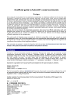
When you start ArtemisRGB, you will see the main image preview area
occupying most of the window. On the left is a list which will contain the
names of all the images to be processed.
Above this are some controls for specifying how the processing is performed,
and at the bottom are buttons for dealing with files.
Page 20
Artemis RGB screen
To import a file, click the ‘Import’ button and locate a FITs file produced by a
colour camera. The name of the file will appear in the list box on the left, and
the image will appear in the preview window. It may not look quite right at this
stage! The ‘Delete’ button can be used to remove an image from the list - it
does not delete it from the hard disk. At the top left is a combo box where you
can select whether to view the raw, colour, or luminance image. The raw
image will show you the checkerboard matrix pattern, but for now we want to
see the colour image. Below this combo box is another one in which you can
select whether the CCD uses a primary (RGB) or secondary (CYMG) matrix.
The ATK-16HRC uses an RGB matrix; the ATK-16C uses a CYMG matrix.
Choose the appropriate one for your camera. If you saved the file from a
recent version of Artemis Capture, the colours should already be correct.
Otherwise you can try adjusting the X and Y offset values, which tell
ArtemisRGB where on the matrix the top left corner of the image lies. For a
full-screen image in the standard orientation these values ought to be 0, 0 but if the image has been rotated or flipped then the values will need
adjusting. With a bit of trial and error you should find values that give the
correct colours.
Most deep sky targets are very faint, and because ArtemisRBG doesn’t have
any histogram stretching tools, a “Brightness” selection is available, which will
allow you to increase the image brightness. This will help to better see the
object in the image, but won’t change the image in any way, since it’s for
display purposes only.
Because some information is lost when the CCD samples the signal into
different colours, reconstructing the full colour image can sometimes introduce
colours which weren’t present in the original scene. These are typically seen
in regions of high contrast. To help reduce these false colour artifacts, you can
Page 21
run a low-pass filter (blur) on the colour channel. Then, to restore sharpness
to the image, you can run a high-pass filter (sharpen) on the luminance
channel.
If you have multiple images loaded into ArtemisRGB, you can give each one
its own set of processing options if you need to. In particular if some images
were saved from a sub frame, then you may need to give them different X or
Y offsets. If you make a multiple selection in the image list, the controls at the
top of the program will indicate any values which are common to all selected
images. If values differ between images then they will be displayed as ‘---’ in
the controls. Changing any value will update that value in all selected images this can be a quick way to set the processing parameters for a batch of
images.
Finally, when you have set all your images as you like them, you can use the
‘Save All’ button to convert all the images to a file format suitable for postprocessing. You can choose to save as separate Red, Green and Blue FITs
files, or a single 3-layer FITs file, or a 48-bit uncompressed TIFF file, or a 24bit BMP file. The last option will lose information, but is more compact and
more widely used than the other formats. When using the first option each
image is saved under its original filename, with _R, _G or _B appended to
indicate the colour channel.
Page 22
9.10 Other controls
There are a few other controls apart from the dialogs described above. The
most important are probably the ‘Camera |Snapshot’ and ‘Camera |Loop’
menu options, also available as the two toolbar buttons (the ‘loop’ button is
the one with the red circular arrow on it). The Snapshot command takes a
single image, and the Loop command starts the program taking repeated
images. You can abort the current exposure by clicking the Snapshot button
while the exposure is in progress. If you want to terminate the exposure early
but keep the result, hold the shift key down while you click the Snapshot
button. When looping, you can stop the whole looping process by clicking the
Loop button again. The current exposure will be aborted. You can change
exposure settings while looping, but they will not be acted upon until the start
of the next exposure.
‘Camera |Subframe’ or the red square toolbar button allows you to drag an
imaging sub-frame using the left mouse button, which is normally used to
scroll the display. You can always use the right mouse button to create a subframe. The green square toolbar button, or the ‘Camera |Fullframe’ option, will
revert to using the full CCD area for imaging.
‘Camera |Rotate 180’ will rotate captured images 180 degrees. This also
rotates the saved image.
‘Camera |Info’ gives some details of the Atik camera.
‘Camera |Connect’ and ‘Camera |Disconnect’ will connect or disconnect the
Atik camera.
‘File |Fits header’ allows you to specify the target object, telescope, and
observer name for recording in the header of saved FITs files.
The ‘Quick’ menu options allow you to take an instant snapshot at a variety of
exposures and binning levels, with a single click or key press.
Page 23
10 Maxim DL™ plug-in
Introduction
Maxim DL is a powerful astronomical program, from Diffraction Limited. It is able to
control most of the equipment used in astronomical imaging, as well as processing the
captured images. In order to allow Maxim DL to communicate with a new piece of
hardware, a driver is required to be installed in a location known to Maxim DL.
Installation
The driver file for the Atik16 camera is located under the “\Plug-ins\MaximDL”
folder on the CD-ROM. To install it, just double click on the
“SetupArtemisMaxim.exe” and follow the prompts. Be aware that you will need top
have Maxim DL installed first.
Using the Plug-in
Once the driver is installed, you can start up Maxim DL and open the CCD Control
Window - either by pressing Ctrl+W or by selecting menu option View|CCD Control
Window. There may be a short pause while Maxim DL build up a list of available
camera drivers, and then you will see the camera setup dialog.
In the box headed 'Main CCD Camera', click the 'Setup' button, and in the dialog
which appears scroll down the 'Camera Model' list until you find the “Artemis”
camera. There will be five boxes at the bottom of the dialog:
• Priority
In order not to 'lock up' Maxim DL while the driver receives data from the camera, a
separate process is created for receiving the data in the background while Maxim DL
deals with other things such as the user interface. On a slower PC, or one which is
particularly busy, it is possible that insufficient time may be available for the
download process resulting in stalls during the data transfer. This is undesirable since
it may produce artefacts in the image, and so the option is given to increase the
priority of the download process. This option will not normally be required, but is
provided as a last resort.
• Hardware FIFO
The Atik 16 camera is fitted with an internal FIFO (First In, First Out) buffer to
smooth the transfer of data from the CCD to the USB. It should be enabled all the
time.
Page 24
• Precharge mode
Here you can select the manner in which the CCD's precharge level is subtracted from
the image data. 'None' returns data without subtracting the precharge level - this is the
fastest option but will result in some image noise. 'PC' sends the image and precharge
data to the PC for subtraction - this is the method which results in the least noise, but
takes up twice the USB bandwidth. 'In-camera' subtracts the precharge data in the
camera's firmware, giving an image which is almost identical to the 'PC' subtraction,
but using half the USB bandwidth.
• Amp off for exposures longer than (seconds)
This option allows you to set threshold exposure duration - for exposures longer than
this, the driver will switch off the CCD's internal amplifier during the exposure.
Leaving the amplifier switched on can cause a slight brightening towards one edge of
the image due to a small but detectable amount of infrared radiation ('amp glow')
emitted by the circuitry inside the CCD, so it is best to switch off the amplifier for
longer exposures. For short exposures the glow is generally insignificant compared to
the brightness of the actual subject being imaged.
• Filter (only for interlaced CCDs)
This filter is to attenuate the effects of “banding” on interlaced CCDs. It should be
used with the Atik 16 (not the 16HR).
Page 25
11 AstroArt Plug-in
Introduction
AstroArt is a powerful astronomical program, from MSB Limited. It is able to control
most of the equipment used in astronomical imaging, as well as processing the
captured images. In order to allow AstroArt to communicate with a new piece of
hardware, a driver is required to be installed in a location known to AstroArt.
Installation
The driver file for the Atik16IC camera is located under the “\Plug-ins\Astroart”
folder on the CD-ROM. To install it, just double click on the “SetupArtemisaa.exe”
and follow the prompts. Be aware that you will need to have AstroArt installed first.
Using the Plugin
Once the driver and user interface files have been copied to the correct directory, you
can start up AstroArt and open the CCD Control panel by selecting menu option
Tools|Plugin Commands|CCD Camera
All being well you will see the camera setup dialog, at the left of which is a dropdown list of supported camera types. Select "Artemis" in this box, and then click
"Check CCD" to connect to the camera. If you see the message 'Connection FAILED'
then you need to check that the camera is correctly powered up and connected to the
USB, and be certain that you have uploaded the correct firmware onto the camera if
required. Otherwise, you should see a dialog in which you can configure some
settings of the Artemis camera prior to using it:
• Amp off for exposures longer than (seconds)
Allows you to set a threshold exposure duration - for exposures longer than this, the
driver will switch off the CCD's internal amplifier during the exposure. Leaving the
amplifier switched on can cause a slight brightening towards one edge of the image
due to a small but detectable amount of infrared radiation ('amp glow') emitted by the
circuitry inside the CCD, so it is best to switch off the amplifier for longer exposures.
For short exposures the glow is generally insignificant compared to the brightness of
the actual subject being imaged.
• Precharge mode
Here you can select the manner in which the CCD's precharge level is subtracted from
the image data. 'None' returns data without subtracting the precharge level - this is the
fastest option but will result in a noisy image. 'Full' sends the image and precharge
data to the PC for subtraction - this is the method which results in the least noise, but
takes up twice the USB bandwidth. 'ICPS' (in-camera precharge subtraction) subtracts
the precharge data in the camera's firmware, giving an image which is almost identical
to the 'full' subtraction, but using half the USB bandwidth.
Page 26
• Hardware FIFO
The Atik 16 camera is fitted with an internal FIFO (First In, First Out) buffer to
smooth the transfer of data from the CCD to the USB. It should be enabled all the
time.
• High Priority
In order not to 'lock up' AstroArt while the driver receives data from the camera, a
separate process is created for receiving the data in the background while AstroArt
deals with other things such as the user interface. On a slower PC, or one which is
particularly busy, it is possible that insufficient time may be available for the
download process resulting in stalls during the data transfer. This is undesirable since
it may produce artefacts in the image, and so the option is given to increase the
priority of the download process. This option will not normally be required, but is
provided as a last resort.
• Filter (only for interlaced CCDs)
This filter is to attenuate the effects of “banding” on interlaced CCDs. It should be
used with the Atik 16 (not the 16HR).
Once you have chosen the settings you require, click 'OK' to complete the connection
with the Artemis camera and return to the Control Panel. Now you can click on the
'Settings' tab to take a test image - select an exposure time and binning mode, then
click the 'START' button. After a while a window will open up containing your Atik
16 image.
If you need to find out more about how to use AstroArt for imaging there is plenty of
information, and some tutorials, available from the AstroArt 'Help' menu.
Page 27