1
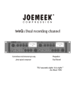
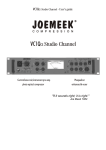
1845 W. 169th Street
Gardena, CA 90247
USA
DISTRIBUTED BY PMI AUDIO GROUP
JOEMEEK
Place
Stamp
Here
TM
mc2
TM
16 14 12 10
PEAK
8
6
4
2
STEREO OPTICAL COMPRESSOR
0
2
mc
+2 +4
-2
0
-4
-10
+8 +4
-4
3:1
10
0.3
5
+9
+8
5:1
2:1
1
50
-15
+5
+12
+3
VU
-30
-2
-25
+16
dB
+15
INPUT
GAIN
+oo
dBu
-20
COMPRESS
1:1
10:1
SLOPE
1
ms
100
ATTACK
0.1
sec
3
RELEASE
S
+2
-4
-20
-40
2
-6
0 +4 +8 +12
-4
ON -24 -15 -9
GR
+4
-6
+6
-8
0
dB
+20
MAKE UP
GAIN
-10
COMP
dBu
-50
GR
HOLD
Joemeek User Guide
visit us on the web at joemeek.com
+8
M
ON
W
STEREO
WIDTH
ON
TM
Joemeek is manufactured and
marketed under the direction of:
PMI AUDIO GROUP
USA: 1845 W. 169th Street
Gardena, CA 90247
toll free: 877-563-6335
fax: 310-323-0900
email: [email protected]
UK: Unit 4 Minerva Court
Woodland Industrial Estate
Torquay, TQ2 7BD
tel: +44 (0)1803-612700
fax: +44 (0)1803-612009
email: [email protected]
Written by Allan Bradford, MSc
4
Important Safety Information
CAUTION
CAUTION: TO REDUCE THE RISK OF ELECTRIC SHOCK, DO NOT
REMOVE COVER. NO USER-SERVICEABLE PARTS INSIDE. REFER
SERVICING TO QUALIFIED SERVICE PERSONNEL.
The lightning flash with arrowhead symbol, within equilateral
triangle, is intended to alert the user to the presence of
uninsulated “dangerous voltage” within the product’s
enclosure that may be of sufficient magnitude to constitute a
risk of electric shock to persons.
The exclamation point within an equilateral triangle is
intended to alert the user to the presence of important
operating and maintenance (servicing) instructions in the
literature accompanying the appliance.
WARNING: TO AVOID FIRE OR ELECTRIC
SHOCK HAZARD, DO NOT EXPOSE THIS
APPARATUS TO WATER, RAIN OR MOISTURE.
This appliance has a serial number located on the rear panel. Please
record the model number and serial number and retain them for your
records.
Model number
Serial number
NOTE — This apparatus does not exceed the Class A/Class B
(whichever is applicable) limits for radio noise emissions from
digital apparatus as set out in the radio interference regulations
of the Canadian Department of Communications.
.
ATTENTION — Le présent appareil numérique n’émet pas de
bruits radioélectriques dépassant las limites applicables aux
appareils numériques de class A/de class B (selon le cas)
prescrites dans le réglement sur le brouillage radioélectrique
édicté par les ministere des communications du Canada.
These limits are designed to provide reasonable protection
against harmful interference in a commercial/residential
installation respectively. This equipment generates, uses,
and can radiate radio frequency energy and, if not installed
and used in accordance with the instruction manual, may
cause harmful interference to radio communications. There
is no guarantee that interference will not occur in a particular
installation. If this equipment does cause interference to
radio or television equipment reception, which can be
determined by turning the equipment off and on, the user is
encouraged to try to correct the interference by any
combination of the following measures: (1) Relocate or
reorient the receiving antenna (2) Increase the separation
between the equipment and the receiver (3) Plug the
equipment into an outlet on a circuit different from that to
which the receiver is connected (4) Consult your dealer or
experienced radio/television technician for additional
assistance.
CAUTION — Changes or modifications to this equipment
not expressly approved by the party responsible for
compliance could void the user's authority to operate this
equipment.
Important Safety Instructions
1. Read these instructions.
2. Keep these instructions.
3. Heed all warnings.
4. Follow all instructions.
5. Do not use this apparatus near water. Do not expose to drips
or splashes. Do not place any objects filled with liquids, such as
vases, on the apparatus.
6. Clean only with dry cloth.
7. Do not block any ventilation openings. Do not install this
apparatus in a confined space such as a book case or similar
unit. Install only in racks designed for the purpose and in
accordance with manufacturers’ instructions.
8. Do not install near any heat sources such as radiators, heat
registers, stoves, or other apparatus (including amplifiers) that
produce heat.
9. Do not defeat the safety purpose of the polarized or
grounding-type plug. A polarized plug has two blades with one
wider than the other. A grounding-type plug has two blades and
a third grounding prong. The wide blade or the third prong are
provided for your safety. If the provided plug does not fit into
your outlet, consult an electrician for replacement of the
obsolete outlet.
10. Protect the power cord from being walked on or pinched
particularly at plugs, convenience receptacles, and the point
where they exit from the apparatus.
11. Only use attachments and accessories specified by the
_ manufacturer.
5
12. Use only with a cart, stand, tripod, bracket, or table
specified by the manufacturer, or sold with the apparatus.
When a cart is used, use caution when moving the
cart/apparatus combination to avoid injury from tip-over.
13. Unplug this apparatus during lightning storms or when
unused for long periods of time.
14. Refer all servicing to qualified service personnel. Servicing
is required when the apparatus has been damaged in any way,
such as power-supply cord or plug is damaged, liquid has been
spilled or objects have fallen into the apparatus, the apparatus
has been exposed to rain or moisture, does not operate
normally, or has been dropped.
15. Apparatus designed with Class-I construction must be
connected to a mains socket outlet with a protective earthing
connection (the third grounding prong).
16. This apparatus may be equipped with a single-pole, rockerstyle AC mains power switch. If so this switch is located on the
front panel and should remain readily accessible to the user.
17. The manufacturer reserves the right to change the
technical specification of the product without prior notice.
6
Statement of RoHS Compliance
PMI Audio Group manufactures complete electronic products
which are covered by the European Union’s “Removal of
Hazardous Substances” directive 2002/95/EC (RoHS). This
directive seeks to eliminate toxic substances from the
manufacturing process, such that when equipment is disposed
of at the end of its life cycle, the materials it contains do not
contaminate the environment and pose health risks. Banned
substances are lead, mercury, cadmium, hexavalent
chromium, polybrominated biphenyls (PBB) and polybrominated diphenyl ethers (PBDE). Lead is used together
with tin in solder connections to reduce the melting point of
solder. Lead-free solder requires higher soldering
temperatures which in turn places greater thermal stress on
components.
RoHS
COMPLIANT
Pb
Statement of WEEE Policy
PMI Audio Group manufactures many complete electronic
products which are covered by the European Union’s “Waste
Electric and Electronic Equipment” directive 2002/96/EC
(WEEE). This directive seeks to ensure that waste electric and
electronic equipment is disposed of in an environmentally
responsible manner, at the end of its life cycle. PMI Audio
Group takes seriously its obligations under this directive to
take back WEEE-affected products and, from 13th August
2005, will mark all such products with the crossed-out wheeled
bin symbol.
PMI Audio Group takes seriously its obligations under the
RoHS directive and insists that its factories use only
components that are certified RoHS compliant, as well as leadfree solder. In a very few cases the necessary components
may not yet be available to the world market but we work
continuously to eliminate any such exceptions at the earliest
opportunity. Our printed Circuit Boards (PCB’s) and all
soldered joints have been lead-free since 2005.
Business to Business products: PMI Audio Group will costneutrally take back WEEE-affected electric and electronic
equipment in this category, from 1st January 2006. PMI Audio
Group will work with disposal and recycling partners working
within the EU. The waste electric and electronic equipment can
then be turned over to a disposal and recycling companies in
the countries concerned.
Business to Customer products: emerging electric and
electronic equipment will be disposed of by local authorities'
collection systems.
Dual Use products: this equipment will be disposed of by local
authorities' collection systems.
Contents
JOEMEEK reborn – the legend grows
mc2 Controls at a Glance...............................................8 & 9
The Next Generation of Joemeek studio processors represents a
quantum leap in the history of the Joemeek legend. Long regarded for
its "Big Sound", the original Joemeek gear was both revered and
reviled for its somewhat "quirky" nature. Now we have taken the best
of what made the Joemeek products sound great, refined it, distilled it,
added to it and repackaged it.
Overview...........................................................................10
Preamplifier........................................................................10
Insert Point .........................................................................10
VU Meter.............................................................................10
Compressor........................................................................11
GR Meter............................................................................13
GR Hold..............................................................................13
Stereo Width.......................................................................13
Outputs...............................................................................13
Using the mc2....................................................................14
Getting Connected...............................................................14
Using the Preamp................................................................14
Using the Compressor.........................................................14
Using the GR Hold...............................................................15
Using the Stereo Width.........................................................15
Using the insert Point...........................................................15
Troubleshooting................................................................16
Technical Specification.....................................................17
7
Properly and robustly engineered for predictable, controllable
performance, the new range retains the famous Joemeek sound, with
its wide, flat frequency response extending from subsonic to
ultrasonic. It also uses genuinely low noise circuitry, with lots of
headroom (immunity to overload). Accurate calibration and metering,
together with clear panel labelling, give you complete confidence in
what's going on. While some equipment pays lip-service to quality and
"professional rules" but fails to deliver, the Next Generation Joemeek
products are founded on good solid electronic and audio engineering,
and withstand direct comparison with the very best names in mixers
and outboard gear.
The Joemeek range provides everything you need to get your
performance onto tape/disc.
About the Designer
The Next Generation of Joemeek has been completely re-engineered
by renowned audio electronics consultant Allan Bradford. With his
background in physics and 30 years experience with the design of
instruments, mixers, processors and amplifiers, Allan's unique range
of expertise ensures that Joemeek remains at the forefront of music
technology.
8
mc2 Controls at a Glance
16 14 12 10
PEAK
8
6
4
2
STEREO OPTICAL COMPRESSOR
0
2
mc
+2 +4
-2
0
-4
3:1
-10
+8 +4
-4
10
0.3
5
+9
+8
5:1
2:1
1
50
-15
+5
+12
+3
VU
-30
-2
-25
+16
dB
+15
INPUT
GAIN
+oo
dBu
-20
COMPRESS
1:1
10:1
1
SLOPE
ms
100
0.1
ATTACK
sec
+2
-20
+4
-6
-40
+6
-8
3
RELEASE
S
-4
2
-6
0 +4 +8 +12
-4
ON -24 -15 -9
GR
0
dB
+20
MAKE UP
GAIN
-10
COMP
dBu
-50
GR
HOLD
+8
M
ON
W
STEREO
WIDTH
ON
INPUT GAIN – sets the amount of audio amplification. Too little gain and the resulting sound will be too quiet; too much and the signal could
become distorted.
PEAK LED – lights 6dB below clipping.
COMPRESS – sets the level of signal (or "Threshold") above which the signal starts to be compressed.
SLOPE – sets the compression ratio applied to signals above threshold.
ATTACK – sets how quickly the compressor responds to peaks above threshold.
RELEASE – sets the time taken for the signal to return to its normal size after compression. In general, the longer the time, the less obvious the
compression.
MAKE UP GAIN – restores the level of the signal after compression.
COMP – switch turns the compressor on. The LED lights when active.
GR HOLD – freezes Gain Reduction at a constant level during gaps in the programme material (ie: prevents the compressor gain rising).
GR Hold ON – switch turns the GR Hold function on. The LED lights when active and changes color to indicate Hold status.
STEREO WIDTH – varies the perceived with of the programme material from Mono, to normal Stereo, to extra Wide.
Stereo Width ON – switch turns the Stereo Width function on. The LED lights when active.
VU METER – 8-Led bargraph shows the output signal level in dB at any given moment.
GR METER – 8-Led bargraph indicates the amount of gain reduction in dB, which is taking place at any given moment.
mc2 STEREO COMPRESSOR
DESIGNED IN THE UK FOR PMI AUDIO.
MADE IN CHINA.
NO USER SERVICEABLE PARTS.
REFER SERVICE TO QUALIFIED PERSONNEL.
OUTPUT
EN55103
www.joemeek.com
INPUT
USE ONLY CORRECT
JOEMEEK POWER SUPPLY
POWER
12V AC
+4dBu
-10dBV
RIGHT
LEFT
S/C INSERT
RIGHT
LEFT
INPUTS – Balanced line level inputs on ¼" TRS jacks.
S/C INSERT – unbalanced "Send and Return" jack allows you to patch other pieces of equipment, into the compressor's control circuitry.
OUTPUTS – Balanced line level outputs on ¼" TRS jacks.
+4dBu/-10dBv – switch selects the operating level of the ¼" jack outputs, either to the professional +4dBu level, or to the -10dBv semi-pro level.
9
10
Overview
Insert Point
The JOEMEEK mc2 is a professional studio-quality stereo compressor in
a compact half-rack format. Simple to use yet extremely powerful, the mc2
will bring out the best in any line-level stereo material and give the gloss of
a professional studio production to all your performances. It can be used
both for recording, mastering and live work.
This is simply an unbalanced "Send and Return" jack on the rear panel. It
allows you to patch other pieces of equipment into the compressor's
control side chain, such as an equalizer or filter. To use it you will need a "Y"
lead wired as follows:
Think of the stereo mc2 as three separate items of equipment:
! A line-level stereo Preamplifier.
! A stereo JOEMEEK Optical Compressor.
! A stereo Width Processor
Tip: send
Ring: return
Sleeve: ground
When no jack is inserted, the socket is internally linked, or "normalled", so
that the control signal flows uninterrupted.
Preamplifier
VU Meter
The front end to the mc2 accepts any type of line level (ie: preamplified)
audio signal. The inputs are electronically balanced. Note: although the
Line inputs are not normally used directly with microphones, they may be
suitable for some high output unbalanced microphones, such as battery
powered Electret types.
The LED VU Meter shows signal level at the outputs. It covers the range
-24dB to +12dB in eight steps. Note that this is relative to the selected
operating level of "+4dBu" or "-10dBv". In other words if you have selected
"4dBu" and the meter reads "0", then you have +4dBu coming out of the
output sockets. If you have selected "-10dBv" and the meter reads "0",
then you have -10dBv coming out of the output sockets.
The Line input jacks are balanced and wired as follows:
Tip: + (hot)
Ring: - (cold)
Sleeve: ground
The "Input Gain" control covers a range of amplification from -6dB to
+15dB. This enables the mc2 to be matched to sound sources at both
-10dBv to +4dBu operating levels. The PEAK LED lights 6dB below
clipping, so occasional brief flashes are OK but if it's on all the time you
need to back the Input Gain off!
Compressor
The hardest device to understand, yet one of the most useful, the
PhotoOptical Compressor is what gives Joemeek products their unique
character. Its job is to make quiet sounds louder and loud sounds quieter,
or in other words to reduce the dynamic range of the programme material.
It's a bit like manually riding the volume control, except the compressor
does it automatically, responding far quicker and more accurately than you
ever could by hand. The compressor is applied in several ways:
1. Make Sounds Stand Out
Because compressors make loud sounds quieter, you can boost the
volume of the quiet bits without the loud bits getting even louder. That
means you can raise the average level of an instrument or vocal in the mix,
which has the effect of lifting it and bringing it forwards. This can actually
improve vocals for example, bringing them out in front of a mix, making
them sound denser, more even, and more confident!
2. Crank Up The Volume
Raising the average volume of whole mixes means they can be heard in
noisy environments, such as vehicles and factories. Boosting the average
level is what makes radio stations sound LOUD and the same technique is
used on TV commercials too, which is why they always seem annoyingly
louder than the movie you were trying to watch!
3. Protection
Fast response times are generally used to control brief transients. In other
words if an occasional peak sticks its head above a maximum permitted
level, the compressor clobbers it; this is known as limiting and a
compressor designed solely for this purpose is known as a Limiter.
Limiters are primarily used to protect recorders and monitor systems from
overload, radio transmitters from overmodulation, etc. The Joemeek
compressor is not primarily intended for this purpose as the Attack is not
really fast enough to satisfy radio station requirements, although it is
generally good enough to protect recorders and monitors, where the effect
11
of transients is less critical. Normally you should not hear a limiter
operating but if it is driven hard constantly, it can render a mix somewhat
flat and lifeless.
4. Accommodation
The dynamic range of the human ear is phenomenal, extending from the
threshold of hearing (eg: a pin dropping onto soft carpet) to threshold of
pain (eg: standing next to a jet aircraft) - some 120dBA in all. By contrast,
vinyl, cassette tape and radio broadcasts all have a dynamic range of
about half that. Since the advent of the CD, the dynamic range of the
medium is far less of an issue and compressors are used more to give a
certain "feel" to a production. AM and FM radio however, is still very much
compressed to fit its restricted dynamic range.
5. Modification
A compressor can change the dynamics, or "envelope" of the track and it is
here that the Joemeek Compressor excels!
Types of Compressor
Most compressors work in essentially the same way: a volume-controlling
element or "gain cell" is inserted into the audio signal path. The level of the
signal at any given moment is measured and that information is used to
control the gain cell. So if the signal gets bigger, the volume is turned down.
Various types of gain cell in common use include FETs, valves (tubes),
light-dependent-resistors (photoelectric), digital potentiometers and
voltage-controlled-amplifiers, better known as VCAs.
The mc2 Compressor is a unique recreation of the sort of photoelectric
compressor used by record producer Joe Meek in the 1960's. Using
modern components for consistency and reliability, it nonetheless
reproduces faithfully the same punchy sound that was so characteristic of
the pop records of that time.
Compression Ratio
What?? OK, it's simpler than it sounds. If the input gets 10dB louder but the
output only increases by 5dB then the compression ratio is "2 to 1". If the
12
input goes up 10dB but the output only goes up 1dB, then the compression
ratio is "10 to 1". In a theoretically ideal compressor, this ratio is the same
for any size of signal above the threshold but for that to be true, the gain cell
and its control circuitry must be perfectly linear over a very wide range. In
practice only compressors based on VCAs and digital potentiometers are
likely to behave in this way.
Some compressors have a control to set the ratio anywhere between 1:1
(ie: no compression), and 20:1 (which would be regarded as a "brick wall
limiter"). In the mc2 the "Slope" or "Compression Ratio" is variable from 1:1
(ie: no compression) to 10:1. Slopes around 3:1 are gentle for vocals while
higher slopes are hard for drums and guitars. However that's not all there is
to it.
Variable Ratio
In the Joemeek optical compressor the compression 'threshold' is not
clearly defined and the compression ratio varies with the amount of
compression applied. Suppose the 'Slope' control is set to 5:1. For signals
only just exceeding threshold, the ratio is little more than 1:1. As the
compressor is driven harder, the ratio rises to 5:1, at least up to a point. It is
a feature of the Joemeek compressor that the compression ratio actually
reduces again during large transients and, adjusted correctly, this helps to
retain brightness that is often lost with other types of compressor. This is
why vintage compressors often sound more lively than their modern
counterparts.
Controls
‘COMPRESS' sets the level of signal (the "Threshold") above which the
signal starts to be compressed. Turning the compression control clockwise
lowers the compression threshold, and drives the compressor harder.
‘ATTACK' sets how quickly the compressor reacts to peaks above
threshold. Turn this control anticlockwise for a quick response. Slower
(clockwise) allows the fast leading edge of percussive sounds to pass
uncompressed for a moment, before the compressor reacts to control the
gain. This example of "changing the envelope" of a sound exaggerates the
percussive nature of drums and other instruments. Settings around midposition are used where the compression needs to be less obvious. Vocals
for example, require Attack times around 10msec for natural sounding
results. Faster attack times (anti-clockwise) in conjunction with large
amounts of compression, result in extreme "pumping" effects.
'RELEASE' sets how long the compressor goes on squashing the sound
for, once the signal has dropped below threshold. If it stopped instantly
there would be very noticeable modulation or "pumping" of the sound. So
we may want it to stop compressing less abruptly and that is what the
Release control is for. Generally, the longer the Release time, the less
obvious is the compression. Of course some "pumping" might actually be
desirable as a special effect and that is another way in which the envelope
of a sound can be modified. The mc2 Release is variable from 100mS up to
3 seconds giving a wide variety of effects.
'MAKE UP GAIN' sets a static amount of amplification, to restore the level
of the signal after compression. Correctly adjusted, there will be no change
in perceived volume as the 'COMP' in/out switch is operated.
How the compressor behaves actually changes with program content and
volume. So experiment with the controls with different kinds of material to
discover the range and depth of effects that can be achieved. The 'COMP'
in/out switch allows comparison between compressed and uncompressed
sound (blue LED lights when active).
'SLOPE' sets the average compression ratio applied to signals above
threshold. Lower settings (anti-clockwise) have less effect. Turning the
control clockwise increases the ratio and makes the effects of
compression more dramatic. At maximum (10:1) the Joemeek compressor
effectively becomes a limiter.
GR Meter
The LED GR Meter provides an accurate reading of gain reduction in dB, at
any given moment.
GR Hold
A problem with all compressors is that when the signal level falls below the
compression threshold, the gain rises to that set by the 'MAKE UP GAIN'
control. The result is that during gaps in the music, any background noise
will be amplified, and may become noticeable and even downright
annoying! This could be counteracted by using a noise gate or expander
gate but such devices introduce their own problems. The mc2's 'GR HOLD'
control works by freezing gain reduction at the level it was at just before the
signal dropped below the compression threshold. In this way there is no
overall increase in gain and the noise floor is preserved.
The adjacent 'ON' switch enables this feature and the LED lights when
active. This LED also changes color to indicate the status of the GR Hold.
Green means a usable signal is present and the compressor is responding
to the program material. Red means that the input signal has fallen below
the selected threshold and the gain reduction is now frozen at its most
recent level.
Stereo Width
This control allows the width of the stereo image to be modified, from
mono, to normal stereo, to extra-wide stereo.
Wide stereo gives the impression of a bigger sound stage and a greater
13
sense of space and depth to a mix. Depending on the mix, it may also
create a sense of improved clarity. The "Mid and Side" technique
employed widens stereo without the dreaded “hole in the middle” effect (ie:
loss of center or bass components). Stereo widened in this way also
remains mono compatible.
The 'ON' switch allows comparison between processed and unprocessed
sound (LED lights when the 'STEREO WIDTH' control is active).
Outputs
CONNECTORS
Left and Right outputs are provided on TRS jacks. The adjacent switch
selects the output operating level to either +4dBu (suits most professional
studio equipment) or -10dBv (suits semi-pro or hi-fi equipment). Check
with the handbook for whatever you are feeding, to find out which level is
required.
The jack outputs are balanced and wired as follows:
Tip: + (hot)
Ring: - (cold)
Sleeve: ground
Balanced or Unbalanced
To run the ¼" jack outputs unbalanced, just plug in mono jack plugs. This
increases the gain of the "+" signal by 6dB, so there is no drop in level
compared with balanced gear.
All outputs on all NextGen Joemeek products are properly balanced, which
is to say there is a signal on both pins! In this way the maximum possible
common-mode rejection of interference, can be achieved at the receiving
end.
14
POWER SUPPLY
Using the mc2
Connect the mc2 Power Supply to the AC connector on the rear panel and
switch on the mains supply. NB: Use only the 12V ac mains adaptor
supplied. Use of any other power supply may damage the mc2 and
will invalidate the warranty.
GETTING CONNECTED
The figure shows the mc2 being used in a typical recording setup:
Using the Preamp
MONITOR AMP
mc2 STEREO COMPRESSOR
Using the Compressor
DESIGNED IN THE UK FOR PMI AUDIO.
MADE IN CHINA.
NO USER SERVICEABLE PARTS.
REFER SERVICE TO QUALIFIED PERSONNEL.
OUTPUT
EN55103
Turn the 'INPUT GAIN' control to minimum and connect the input source.
Turn up the 'INPUT GAIN' until the sound registers on the VU Meter,
adjusting it so that the meter reads between "0" and “+4” on sound peaks.
When the red LED (labeled "Peak") lights, the mc2 is within 6dB of clipping.
Occasional flashes are OK but if it is on all the time, turn the Input Gain
down!
EQUALIZER / FILTER
(MONO)
www.joemeek.com
INPUT
USE ONLY CORRECT
JOEMEEK POWER SUPPLY
POWER
12V AC
+4dBu
-10dBV
RIGHT
LEFT
RECORDER
S/C INSERT
RIGHT
LEFT
MIXER
! The insert point is being used to divert the compressor control signal
through an external graphic equalizer, for "frequency conscious"
compression.
! If you have a mixer with L-R Master sends and returns, this is a good
place to connect the mc2, for both mastering and live work.
combinations to discover what best suits the material you wish to
compress. Watch the GR meter and don't overdo things - it's possible to
apply 20dB of gain reduction before you realize it!
Use the 'COMP' switch to make comparisons between compressed and
uncompressed signals.
Using the GR Hold
Note that this works only in conjunction with the Compressor – it has no
effect on its own. It is for use with a noisy original signal, such as from
cassette tape, guitar amplifiers or live recordings where a lot of unwanted
background noise is present.
With a signal present, set the compressor to give a moderate amount of
gain reduction and wait for gaps between the music or program material.
You should then hear the noise increase as the compressor's gain returns
to the level set by the 'MAKE UP GAIN' control. Next switch on the GR Hold
and repeat that section of the program. Adjust the 'GR HOLD' control until
the LED just changes from green to red when the music stops. Red means
that the input signal has fallen below the selected threshold and the
amount of gain reduction is being held constant. Green means that the
noise is still above the selected threshold and the compressor is still
working, so raise the threshold by turning the control clockwise.
If the results are not obvious, try increasing the compressor's Release
time. If the gain reduction releases too quickly, the GR Hold may not
capture it before the gain starts to rise again. Keep repeating the process
until the desired effect is obtained and there is no increase in noise during
gaps in the program.
Another thing to note is that this feature uses an analogue "sample and
hold" circuit to freeze the control voltage to the compressor. As with all such
circuits, the stored voltage will eventually decay away, then the
compressor's gain will increase and the noise will again become apparent.
15
Start with the Compressor off and adjust the INPUT GAIN so that the VU
Meter reads around 0dB.
Set 'COMPRESSION' and 'ATTACK' fully anti-clockwise, with 'SLOPE'
and 'RELEASE' at mid-position. Press the 'COMP' switch and turn up the
'COMPRESSION' control until the compressor GR meter starts to read
4dB or 6dB on audio peaks. You should now be able to hear the
compressor working as the volume diminishes. Use the 'MAKE UP GAIN'
control to restore the signal to its previous (uncompressed) level. Alter the
'SLOPE' and listen to how the severity of the gain reduction changes. Try
changing the Attack and listen for percussive sounds getting louder.
Reducing the Attack and Release times should emphasize this even more
and the compressor should start to "pump" audibly.
The overall result of compression depends on the combined settings of the
Compress, Slope, Attack and Release controls. Experiment with different
However this process will take several minutes – long enough the cover
the noisy gaps in the program material, or between tracks of an album. At
the end of the recording, remember to fade out the signal before the noise
comes back!
Using the Stereo Width
With the 'STEREO WIDTH' control centered, normal stereo is maintained.
So with a stereo signal you should hear no difference.
Turning the control fully anticlockwise results in mono, ie: identical signals
come out of both left and right outputs. Turning the control fully clockwise
widens the sound stage to extra-wide stereo.
Use the adjacent 'ON' switch to make comparisons between processed
and unprocessed sound. When widening the stereo image you may find
that “less is more” and it's better to keep the effect subtle.
Using the Insert Point
This unbalanced "Send and Return" jack allows you to patch other pieces
of equipment, such as a graphic equalizer into the compressor's control
circuitry, for "frequency conscious" compression.
If you boost certain frequencies with an external equalizer, those
frequencies are going to cause the compressor to respond more, ie:
squash the program material more. If you cut certain frequencies, the
compressor will respond less to those frequencies. Uses for this can be
either creative or corrective.
Imagine you are trying to even out the vocals in a mix, but the mix is bassheavy with the result that each bass note squashes the vocals. A modest
amount of bass-cut on the external equalizer will make the compressor
16
respond less to the bass, allowing it to do its job of controlling the vocals.
On the other hand, you might want to have a vocal or a drum beat
deliberately “duck” the rest of the mix for special effect. Tune the external
equalizer to the frequencies of the instrument you want to emphasize, then
adjust the 'COMPRESS' control so that the compressor only operates
when those frequencies are present.
Note that none of this external equalization is audible as such.
Troubleshooting
1) No Power (no lights work)
! Is the power supply plugged in (both ends)?
! Is the mains power on?
! Has a mains fuse blown?
5) The Stereo Width doesn't work
! Is the 'ON' switch in (LED on)?
! Is only one input connected?
! Is the programme material mono?
2) The Inputs don't work
! Is the source connected to the jack inputs on the back of the unit?
! Is the 'Input Gain' control turned up?
6) Too much noise
! Is the 'Input Gain' control too high (eg: the input signal is too small)?
! Is the noise already present in the input signal? (Try removing the
input).
! Is the 'Make Up Gain' control too high (eg: when lots of compression is
being used)?
! Try using the GR Hold function to compensate for compressoraccentuated noise.
3) The compressor doesn't work
! Is the 'Comp' switch in (LED on)?
! Is the 'Compress' control turned up enough?
! Is there enough signal, as set by the 'Input Gain' control, to drive the
compressor?
! Is the 'Slope' control turned up enough?
4) Too little or too much compression
! Turn the 'Input Gain' control up or down respectively, to adjust the
signal level to the compressor.
! Turn the 'Slope control up or down respectively.
Technical Specification
Input impedance
Pre-amp overall gain
Common mode rejection
Equivalent input noise
Distortion
Frequency response
Maximum input before clipping
Headroom before clipping
Compression threshold
Compression ratio
Compressor attack time
Line: 20kohm
-6dB to +15dB
70dB
-95dBu (unweighted)
0.001% (below Compressor
threshold)
10Hz to 70kHz (-3dB)
+19.5dBu
+19.5dBu
Compressor release time
-6dBu to +22dBu (variable)
1:1 to 10:1 (variable)
1 msec to 100 msec
(adaptive)
0.1 sec to 3 sec (adaptive)
GR Hold threshold
-10dBu to -50dBu (variable)
Stereo Width range
Mono / stereo / wide stereo
(variable)
GR Meter
VU Meter
8 segment bargraph
8 segment bargraph
Nominal output levels
Output impedance
Output Level switch
Noise Floor
+4dBu/-10dBv
75ohm
12dB attenuation
-95dBu (typical, with 0dB
Input and Make Up gain)
12V ac mains adaptor
12W
220W x 44H x 180D (overall)
1 kilo
Power supply
Power consumption
Mechanical
Weight
17
7) Sounds distorted
! Is the 'Input Gain' control too high?
! When using the compressor, is the Release control set too low?
! Is the GR Hold on with the control set too low?
Notes
Joemeek Limited Warranty
THIS PRODUCT IS FOR PROFESSIONAL USE ONLY
PMI Audio Group warrants that all products will be free from defects in
material or workmanship:
A: For a period of one (1) year from the date of purchase (hereinafter the
labor warranty period). PMI Audio Group will repair or replace this
Product if determined to be defective. After the expiration of the labor
warranty period, the Purchaser must pay labor charges.
B: In addition, PMI Audio Group will supply, at no charge, replacements
for defective parts for a period of one (1) year from the date of purchase.
During the labor warranty period, to repair the Product, the Purchaser
must return the defective Product, freight prepaid, or deliver it to a PMI
Audio Group Service Center. The Product to be repaired is to be
returned in either its original carton or a similar package affording an
equal degree of protection. PMI Audio Group will return the repaired
Product freight prepaid to the Purchaser. PMI Audio Group is not
obligated to provide the Purchaser with a substitute unit during the
warranty period or at any time.
Conditions of Warranty
1. Notification of claims: Warranty Service: If Purchaser discovers that
the Product has proven defective in material or workmanship, then
written notice with a full explanation of the claim shall be given promptly
by the Purchaser to PMI but all claims for warranty service must be made
within the warranty period. If after investigation PMI determines that the
reported problem was not covered by the warranty, Purchaser shall pay
PMI for the cost of investigating the problem at it's the prevailing timeand-materials rate. No repair or replacement by Purchaser of any
Product or part thereof shall extend the warranty period as to the entire
Product. The specific warranty on the repaired part only shall be in effect
for a period of ninety (90) days following repair or replacement of that
part or the remaining period of the Product warranty, whichever is
greater.
2. Exclusive Remedy: Acceptance: Purchaser’s exclusive remedy and
PMI’s sole obligation is to supply (and pay for) all labor necessary to
repair any product found to be defective within the warranty period and
to supply, at no extra charge, new or rebuilt replacements for defective
parts. If repair or replacement fails to remedy the defect, then and only in
such an event, shall PMI exchange to Purchaser a new or reconditioned
unit. Purchaser’s failure to make a claim as provided in paragraph 1
above or continued use of the product shall constitute an unqualified
acceptance of such Product and a waiver by Purchaser of all claims
thereto.
3. Exceptions to Limited Warranty: PMI shall have no liability or
obligation to Purchaser with respect to any Product subjected to abuse,
negligence, accident, modification, failure of the end-user to follow the
operating and maintenance procedures outlined in the users manual,
attempted repair by non-qualified personnel, operation of the unit
outside of the published environmental and electrical parameters, or if
such Product’s original identification (trademark, serial number)
markings have been defaced, altered, or removed. PMI excludes from
warranty coverage, Products sold AS IS and/or WITH ALL FAULTS and
excludes used products which have not been sold by PMI to the
purchaser. PMI also excludes from warranty coverage consumables
such as fuses and batteries, tubes, etc.
4. Proof of Purchase: The dealer’s dated bill of sale must be retained as
evidence of the date of purchase and to establish warranty eligibility.
5. Grey Market: All warranties apply only to PMI Audio Group Products
purchased and used in the USA, and to PMI Audio UK Products
purchased and used in the UK, EU and all other countries outside of the
USA. All warranties apply only to PMI Audio Group/PMI Audio UK
Products originally purchased from an authorized PMI Audio Group/PMI
Audio UK dealer. PMI Audio Group/PMI Audio UK Product that was not
purchased through an authorized and legitimate sales channel is
considered "Grey Market". Warranties for PMI Audio Group/PMI Audio
UK Products purchased outside their respective territories will be
covered by the PMI Audio Group/PMI Audio UK Importer for that specific
country or region. Products originally sold to the USA market and
consequently resold overseas forfeit their warranty as do PMI Audio UK
Products sold outside of the UK and Europe. American PMI Audio Group
Dealers are expressly forbidden to export PMI Audio Group Products
and PMI Audio UK Distributors and Dealers are expressly forbidden to
export to North, South, Central and Latin America. "Grey Market"
purchases are not covered by any warranty. In the case that a PMI Audio
Group/PMI Audio UK Product must be returned to the factory from
outside its respective territory, customer shall adhere to specific
shipping, customs, and commercial invoicing instructions given with the
Return Authorization as PMI Audio Group/PMI Audio UK will not be
responsible for transportation costs or customs fees related to any
importation or re-exportation charges whatsoever.
Owners Registration Card
Disclaimer of Warranty
TO BE COMPLETED AT TIME OF PURCHASE
EXCEPT FOR THE FOREGOING WARRANTIES, PMI HEREBY DISCLAIMS AND
EXCLUDES OTHER WARRANTIES, EXPRESS OR LIMITED, INCLUDING BUT
NOT LIMITED TO ANY/OR ALL IMPLIED WARRANTIES OF MERCHANTABILITY,
FITNESS FOR A PARTICULAR PURPOSE AND/OR ANY WARRANTY WITH
REGARD TO ANY CLAIM OF INFRINGEMENT THAT MAY BE PROVED IN
SECTION 2-312(12) OF THE UNIFORM COMMERCIAL CODE AND/OR IN ANY
COMPARABLE STATE STATUTE. PMI HEREBY DISCLAIMS ANY
REPRESENTATIONS OR WARRANTY THAT THE PRODUCT IS COMPATIBLE
WITH ANY COMBINATION OF NON-PMI AUDIO PRODUCTS PURCHASER MAY
CHOOSE TO CONNECT TO THE PRODUCT.
Name ________________________________________
Date of Purchase ________________________________
Serial Number __________________________________
Limitation of Liability
Dealer’s Name _________________________________
THE LIABILITY OF PMI, IF ANY, AND PURCHASER’S SOLE AND EXCLUSIVE
REMEDY FOR DAMAGES FOR ANY CLAIM OF ANY KIND WHATSOEVER,
REGARDLESS OF THE LEGAL THEORY AND WHETHER ARISING IN TORT OR
CONTRACT, SHALL NOT BE GREATER THAN THE ACTUAL PURCHASE PRICE
OF THE PRODUCT WITH RESPECT TO WHICH SUCH CLAIM IS MADE. IN NO
EVENT SHALL PMI BE LIABLE TO PURCHASER FOR ANY SPECIAL, INDIRECT,
INCIDENTAL, OR CONSEQUENTIAL DAMAGES OF ANY KIND INCLUDING, BUT
NOT LIMITED TO, COMPENSATION, REIMBURSEMENT OR DAMAGES ON
ACCOUNT OF THE LOSS OF PRESENT OR PROSPECTIVE PROFITS OR ANY
OTHER REASON WHATSOEVER.
RETAIN FOR YOUR RECORDS
PLEASE DISPATCH AND RETURN
YOUR REGISTRATION
TO JOEMEEK WITHIN 14 DAYS
OF PURCHASE
Information in this User Guide is subject to change without notice. No part of this User Guide may be
reproduced or transmitted in any form or by any means, electronic, mechanical or by any other
means, for any purpose, without the express written permission of PMI Audio Group.
PMI Audio Group may have trademarks, copyrights or other intellectual property rights covering the
subject matter of this User Guide. Except as expressly provided in any written agreement from PMI
Audio Group, the furnishing of this User Guide is provided for the sole use of the authorized User (or
Service Agent where applicable) and does not give the User any license to use any trademarks,
copyrights or other intellectual property of PMI Audio Group.
Specifications and model numbers are subject to
change without notice
PMI, PMI AUDIO, TED FLETCHER, MEEQUALIZER, STUDIO PROJECTS, JOEMEEK, TOFT
AUDIO DESIGNS, CURRENTSENSE, MEEKROPHONE, TRAKPAK and (If it Sounds Right... It is
Right) are either registered trademarks or trademarks of PMI Audio Group in the USA and/or other
countries.
Copyright © 2005 PMI Audio Group. All rights reserved.
Product Registration Information
Please Fill in the Below Sections and Return
Name:
Address:
City:
State:
Zip Code:
Telephone Number:
email Address:
Model Purchased:
Date Purchased:
Serial Number:
Dealer:
Comments:
What magazines do you read to inform your buying decision: (check all that apply)
1 1
MIX
Electronic Musician
1 1
EQ
Sound on Sound
1
Pro Audio Review
1
Recording
1
Pro Sound News
1
Audio MIDI