1
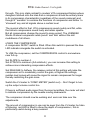
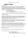
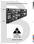
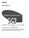
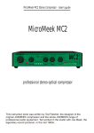
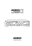
VC1QCS Studio Channel - User's guide
JOEMEEK
C O M P R E S S I O N
VC1QCS Studio Channel
CurrentSense mic/instrument pre amp
photo optical compressor
Meequalizer
enhancer/de-esser
"If it sounds right; it is right."
Joe Meek 1964
VC1QCS Studio Channel - User's guide
1
VC1QCS Studio Channel - User's guide
INSTRUCTION BOOK CONTENTS
The JOEMEEK Studio Channel VC1Q
- What it is and why
3
1. The input amplifier
Noise
Balanced and unbalanced
3
4
5
2. The Compressor
Using the compressor
Compressor control explanations
Compression problems
7
8
9
10
3. The gain make up amplifier
10
4. Meequalizer
11
5 The enhancer
Using the enhancer
11
12
Connecting up the equipment
13
Front panel controls
14
Technical specification
15
Digital Upgrade
18
Regulations and safety
- Warranty
19
Ted Fletcher
This instruction book was written by Ted Fletcher; the designer of the
original JOEMEEK compressor and the whole JOEMEEK range of
professional audio equipment. Ted worked in the studio with Joe Meek, the
2
VC1QCS Studio Channel - User's guide
THE JOEMEEK Studio Channel VC1
The JOEMEEK STUDIO CHANNEL VC1 is a development of historic tried
and tested circuits and designs from the 1960's to the present day,
combined in a single outboard rack unit by acknowledged leaders in
analogue technology.
WHAT IT IS AND WHY:
The JOEMEEK Studio Channel is the result of continuing experimental and
development work carried out over a 5 year period to incorporate the best
of historically excellent sounding technology in a single package to bring the
finest possible sounds within the reach of the studios of today. It's best to
think of the Studio Channel as five separate pieces of equipment:
1) Input amplifier.
2) Compressor.
3) Gain make-up.
4) Meequalzer.
5) Enhancer.
JOEMEEK
Compression
5
40
6
0
JOEMEEK
7.3ms
9
2
0.5ms
11
1
Comp
-20
-10
9.1ms
10
1
60
-7 -5
5.5ms
8
3
-5
Studio Channel VC1Q
Attack
7
4
10ms
40
0
20
-3 -2 -1
60
80
VU
1.25s
100%
LF
0
1
-2
2
3
+
MeQ
0
MF
-2
+2
-6
-6
-12
-12
-15
100Hz
+15
0
MFf
+2
1.8k
+15
1k
2k
HF
2.2k
-2
0
+2
+6
+12
-15
4k
-15
8KHz
+15
0
2
Input Gain (dB)
3
+3
2s
4
5
Mic in Phantom
Instrument In
Slope
+4
0.25s
1
2.5s
VU In/Out
Mode
Release
11
Drive
1
11
Q
De-ess
Enhance
Effect
-20
+6
Output gain (dB)
1. THE INPUT AMPLIFIER
The microphone amplifier takes the audio signals from any microphone and
amplifies them up to 'line' level; that is, from a few millivolts, up to about a
volt. This function is not too difficult and the microphone amplifiers on
normal professional mixers do it quite well; BUT they cut costs and corners.
The JOEMEEK Studio Channel has an uncompromising approach, it uses
JOEMEEK’s latest current sensing microphone input, allowing the use of
virtually any microphone type while providing fantastic frequency response
and the lowest possible noise and distortion. By using the finest
components available for the purpose, and with proven high overload
amplifier design developed over many years, the performance is startlingly
good and silky smooth in sound.
3
VC1QCS Studio Channel - User's guide
Best results are achieved by using a quality condenser microphone, such
as the JOEMEEK JM47 or even tube based TB-47. A new design of
phantom power system assures adequate power for any 48V phantom
microphone.
Dynamic or ribbon microphones should be used with the phantom power
turned off, then full advantage can be taken of the extreme low noise
performance of this amplifier.
ALWAYS be sure that there is a microphone plugged into the input of the
VC1Q before turning up the input gain. Where this is a capacitor
microphone, be sure that the phantom power is turned on. The Joemeek
VC1Q is capable of very high gain, very much more than most microphone
preamplifiers. While this is essential for professional use, it means that if
not set up correctly, the VC1Q could appear to be noisy. ALWAYS adjust
the input control to make sure that the high levels of sound expected
through the unit make the VU meter indicate well into the red region. This
operation is quite normal as the overload margin of the VC1Q is very high.
(once the VU meter is reading +3, there is a further 22dB available before
distortion takes place). Similarly, remember that the output level from the
VC1Q can be very high, so keep the gain settings of following equipment
set low. - This also applies to monitoring settings.
PHASE SHIFT and QUALITY
It's Fletcher Company theory that 'big' sounds are only possible if the
recording channel keeps the response and phase of the lower frequencies
flat and under control. To achieve this, the JOEMEEK Studio Channel has
an extended frequency range down below 10Hz. This ensures that there
are no sudden phase shifts in the low end. The proof of the theory is that
the sound from the Studio Channel is characteristically full bodied and
rounded in character. Such extreme LF response can often bring its own
problems, so a 'subsonic' (High Pass) filter can be switched in with a front
panel push-button.
OVERLOAD MARGINS.
In the mid 1970s Ted Fletcher designed a range of mixers specifically for
use by the Independent Broadcasting Authority and the BBC. One of the
specification clauses insisted on by them was an extreme overload margin
in the microphone amplifier.
The reason for this additional margin was that although momentary
4
VC1QCS Studio Channel - User's guide
overloads (transients) are not audible, they have an effect on perceived
quality. A high overload margin amplifier simply sounds better.
Nowadays, many of these notions have been forgotten and 'quality'
electronics is getting rarer and rarer. But the JOEMEEK Studio Channel
applies these professional rules and achieves a clean transparent sound.
3 TYPES OF INPUTS
The Studio Channel is optimised for the three main types of inputs found in
recording studios. Microphone, Line and instrument.
XLR Microphone inputs are on the front and rear of the unit.
On the rear of the unit, the line input is balanced and is suitable for use with
any other 'zero level' studio equipment. The balancing circuit is
electronically floating balanced using the 'Superbal' electronic circuit
designed by Ted Fletcher in the mid 70's. The circuit gives excellent
rejection of electrical interference.
On the front of the unit there is an unbalanced 'instrument' input designed
with gain and impedance specifically for guitars or basses. Use of this
socket disables the rear line input.
BALANCED AND UNBALANCED
The JOEMEEK Studio Channel is designed to be used in the best studios
where most (if not all) interconnections are 'balanced'. Balanced operation
means that the audio is carried on two wires working in opposite phase.
Then should any interference appear on the 'line' , it will be effectively
cancelled out.
Both of the main inputs (Microphone and Line) and the two main outputs
are accurately balanced to get best advantage from true balanced
operation; but unbalanced operation (for line level signals) will NOT
degrade the performance unless very long cables are used (above 50
metres).
OPERATING THE MICROPHONE AMPLIFIER
Press in the 'MIC/LINE' switch. (in for MIC and out for LINE).
5
VC1QCS Studio Channel - User's guide
Turn the INPUT GAIN knob down to minimum then, If you are using a
capacitor microphone, plug in the microphone, then switch on the phantom
power by pressing in the 'Phantom' switch. (Do it in that order). NOTE.
Some phantom powered microphones take several minutes to reach correct
working conditions. Remember to switch on at least 5 minutes before using
the microphone.
Turn up the INPUT GAIN until sound registers on the VU meter (VU switch
in). Do not let the VU needle hit the end stop too hard or overload may
possibly happen. The meter electronics has been adjusted so that it is
normal for the needle to move in the red area.
OVERLOAD MARGIN AND THE VU. METER
For steady tones, the '0' on the VU meter corresponds to 0dBu (Where
0dBu is 0.775v RMS on the line output with the output control set at '0').
This setting of '0' is to allow for the considerable under-read that occurs with
all VU meters with music signals. It is normal for the peaks of signals to go
to +10dBu while the VU meter reads only '0'. In practice, when the VU
meter is peaking at or just above '0' the music signal will be well within
normal limits and will have a significant overload margin. Even with the
needle hitting the end stop, the signal will not be distorted; although the
overload margin will be reduced.
(The VU meter is connected before the output gain control)
6
VC1QCS Studio Channel - User's guide
2. THE COMPRESSOR
And now for the part of the JOEMEEK Studio Channel that gives it
character; - the compressor.
The compressor is a photoelectric device where the sound triggers light
emitting diodes which in turn control the resistance of a photo sensitive
resistor. This form of compression used to be common in the 60's and 70's
but has been superseded by so called 'improved' voltage controlled
amplifiers. The advantages of the older system are that distortion is virtually
nil, noise is extremely low while overload margin is extremely good. The
disadvantages are that the design is more difficult to produce cheaply and,
according to those who judge equipment by specifications and not by
listening, the older design is less flexible in operation and ‘more difficult to
use’. JOEMEEK begs to differ!
Using 1990's electronics for the control circuitry, Ted Fletcher has recreated
the compressed sound of the 60's; a sound that was unlikely ever to be
heard again. Totally unlike a modern compressor, it can pull voices forward,
help with internal mix balance, and add 'presence' to the sound as well as
controlling recording volume levels. But its main and unique attribute is its
ability to produce the characteristic 60's compressed exciting sound without
losing the transient sparkles that are such a feature of good digital
recording.
THE COMPRESSOR; TECHNICALLY
To get the best use out of the compressor it is necessary to understand the
basic physics and what it is designed to do.
A LIMITER is a device which stops the output of a signal path going above
a predetermined level.
A COMPRESSOR is a device which reduces the dynamic range of
programme material.
WHAT IS A COMPRESSOR?
A perfect compressor is an amplifier where the input/output ratio is
constant: So using a 2:1 compressor, increasing the input by 2dB gives a
corresponding 1dB increase in the output. Early compressors which used
variable mu thermionic tubes or photoelectric devices only approximated
true compression over a limited range. They had a soft 'threshold' where
compression started and held to a predictable ratio up to a certain level,
then they returned to a more linear amplification allowing transients
7
VC1QCS Studio Channel - User's guide
through. This is in stark contrast to modern VCA compressor/limiters where
designers latched onto the idea that a compressor should be entirely linear
in its compression characteristic (regardless of the sound produced) and
thought it 'sensible' to combine the functions of compressor and limiter to
'stonewall' any and all signals above a certain level.
The musical effect is that VCA compressors sound muddy and flat, while
the historic compressors sound lively and retain sparkle.
But all compressors change the sound to some extent. The JOEMEEK
Studio Channel compressor adds 'punch' and 'bite' without the dull
muddiness of all others.
USING THE COMPRESSOR
A compressor IN/OUT switch is fitted. When this switch is pressed the blue
LED indicator alongside the switch is activated.
To USE the compressor, set the COMPRESSION control to somewhere
near full up.
Set SLOPE to number 4.
Set ATTACK to minimum (full anticlock) you can increase this setting to
achieve more interesting compression effects.
Set RELEASE to halfway the release control at this setting will make the
compressor act to moderately control the gain, at higher the settings,
sudden loud noises will cause the signal to remain compressed for longer
thereby restricting the gain more.
Switch the VU meter to 'COMP. METER' (switch out). - Don't forget to turn
up the output volume control too.
If there is sufficient audio signal from the input amplifiers, the meter will start
to indicate compression by the needle moving downwards.
The compressor should now be working and ears can take over the
adjustments.
The amount of compression in use can be seen from the VU meter; but also
a flickering red LED is fitted to show the depth of compression;- this is
particularly useful during a busy session!
8
VC1QCS Studio Channel - User's guide
COMPRESSOR CONTROL EXPLANATIONS
‘COMPRESSION' simply adds gain to the compression sidechain and so
increases compression. In simple terms this changes the 'threshold' of the
compression although with this compressor the 'threshold' is not clearly
defined; the compression starts very gradually and the compression ratio
changes radically with programme content and amplitude.
For practical purposes, winding up the compression control increases the
amount of compression. In use, all controls are interrelated.
'SLOPE' This 5 way switch sets the ratio of compression. Setting ‘1’ is very
gentle compression while ‘5’ can give 'pumping' effects, especially with a
shorter release time.
‘ATTACK' sets the time that the compressor takes to act. At minimum
(fastest) it is possible to make it 'overshoot' on some percussive programme
material: This means that the compression electronics are driven hard
before the gain has been controlled by the light cells. The cells catch up
and overcompress momentarily giving a tiny dip immediately following the
start of the 'note'. This is best demonstrated when recording drums. With
Slope set to maximum, and attack and release to fastest. Used sparingly
this can contribute to musical drive.
Slower attacks are used where the compression needs to be less obvious.
'RELEASE' sets the time during which the path gain returns to normal after
compression. Generally, the longer the time, the less obvious is the
compression.
AMOUNTS OF COMPRESSION.
There can be no rule as to the correct amount of compression for any
particular programme material. Compression (particularly the JOEMEEK
compressor) is a creative effect for the producer.
In rock music, it is possible to use considerable amounts of compression
(10dB or more) and still for the effect to be slight. in classical recording,
conventional compression is frowned upon but the JOEMEEK compressor can
be used to great effect if handled gently.
9
VC1QCS Studio Channel - User's guide
COMPRESSION PROBLEMS
1) Got signal going through but no compression.
Is the compressor switched in?
Is there enough signal?
- A high signal is required to make the compressor operate.
Have you turned the COMPRESSION control high enough?
- is the slope switch turned high enough?
2) It's noisy.
The compressor itself is extremely quiet, but by definition compressors raise
the level of quiet passages; this also means that if there is noise in the
microphone channel (in the audio signal that is being amplified), there will
be more noise on the compressed signal. It's a compromise.
3) It distorts.
No it doesn't! Distortion inside the compressor is virtually impossible,
however it is possible that the microphone amplifier is set with too much
gain; turn down the COMPRESSION control and readjust the microphone
amplifier gain.
4) I can't make the compression gentle enough!
It takes practice. The setting of the Attack control close to fastest is quite
critical, as is the compression control. Also, longer release times lead to a
less noticeable compression effect
3. THE GAIN MAKE-UP AMPLIFIER
The JOEMEEK compressor is essentially a passive piece of electronics.
That means that under compression, when the audio signals are being
pushed down in compression, there needs to be a high grade amplifier after
it to bring the audio signal back to normal volume.
Additionally, the new Studio Channel has a gain make-up stage with an
integral output volume control. The design of this stage is unusual as the
volume control circuit acts around the amplifier minimising any amplifier
noise.
The VU meter operates before the output gain make-up amplifier so that the
VU meter can be used meaningfully at any output volume setting.
10
VC1QCS Studio Channel - User's guide
4. MEEQUALIZER
The equaliser fitted to the VC1Q is similar to the original Joemeek Vc5; that
is, a simple shelving High frequency and low frequency equaliser, with a
mid frequency lift and cut, with selectable frequency. This equaliser is
similar to early frequency correction circuits used in recording studios in the
late 1960s. It is musical in its effect and can produce wide and dramatic
variations without unpleasant side effects. The equaliser is placed in the
circuit immediately following the compressor.
The on/off push-button switches the circuit into operation. The LF (low
frequency) gives shelving lift and cut of up to 15dB at 100Hz. The mid
frequency control gives peaking lift and cut of up to 15dB at frequencies
selectable between about 750Hz and 4KHz (the front panel markings are
conservatively set at 1K to 4KHz). The 'Q' or bandwidth of the mid is set at
approx. 1.2 with the lift or cut at maximum, so that the effect of all but the
most extreme lifts and cuts will be musically pleasant to listen to. The HF
(high frequency) control gives shelving lift and cut of up to 15dB at 8KHz.
When using the equaliser, bear in mind that lifting any EQ will increase the
volume level in the channel and so can reduce the overload margin. Be
prepared to turn down the input gain to compensate.
5. THE ENHANCER
WHAT IS AN ENHANCER?
An enhancer (or exciter) adds a particular type of sparkle to sounds,
particularly voices. It appears to create brightness from sounds that were
'flat'. Recent design changes in the JOEMEEK enhancer give the added
facility of a ‘DE-ESS’ mode. This introduces harmonics into the signal path
that are out of phase with the original musical signal. The effect of this is to
cancel out these harmonic effects, then the effect is similar to a de-esser.
The enhancer in the JOEMEEK Studio Channel works by picking off the
higher frequency part of the sound, compressing and dynamically altering it,
filtering off the original sound and remixing the resulting harmonics back
with the signal. It adds (and now can subtract) high frequency sparkle,
making singing voices sound more present and exciting (or less sibilant)
without some of the other hissy effects you get from simply turning up the
HF equaliser. It is definitely a 'suck-it-and-see' device. Used properly it can
11
VC1QCS Studio Channel - User's guide
create beautiful sounds. Overused it can be horrible.
USING THE ENHANCER
Once a signal is going through the Studio Channel, press the ‘IN/OUT’
push-button (which turns on the green LED), turn up the 'DRIVE' control
until the yellow Enhance LED starts to brighten on peak sounds. Turn up
the ENHANCE control until the sharpening of the sound is obvious, then
adjust the 'Q' control and the 'DRIVE' control to get the required effect. The
EFFECT control adds or subtracts the enhancement so if set between
enhance and de-ess, there is no effect. Turning clockwise from the ‘no
effect’ mark adds enhancement, anticlockwise subtracts enhancement.
Once the effect is audible, experiment with the three controls to get the
desired sound, the controls are very much interdependent and musically
related.
'DRIVE' affects the depth and 'tone' of the enhancement.
RESONANCE or 'Q' affects the length of the high frequency harmonic after
the syllable that created it.
CAUTION. If in any doubt at all, leave enhancement till the mixdown; its
easy to put on but impossible to take off!
NOISE IN THE ENHANCER
Under many normal conditions of use, the enhancer has the effect of
amplifying selected narrow frequency bands in the upper mid range. The
danger is always to overuse the enhancer: This has the effect that any
noise sounds particularly 'scratchy'. The problem is that the existence of
these frequencies is common in quality recording. The effect can be
reduced to almost nothing with careful use of the drive and enhance
controls; but it does take practice.
NOTE; when the enhancer is not being used, keep the 'ENHANCE' control
to a minimum, or IN/OUT switched out. this will eliminate any slight noise
that may be amplified by the enhancer circuitry.
BALANCED OUTPUT
The line level output from the Studio Channel is electronically balanced with
a discrete 'floating' circuit which has the capability of driving up to +26dB
into balanced circuits. The circuit performs like an audio transformer.
12
VC1QCS Studio Channel - User's guide
CONNECTING UP THE EQUIPMENT
MICROPHONE
The microphone input is an XLR connector. There is a connector fitted to
the front and the rear panel for convenience. ONLY ONE OF THE
CONNECTORS SHOULD BE USED AT ANY ONE TIME they are wired in
parallel. For best results the microphone used should be balanced 200
ohm impedance Connections are
Pin 1 is ground or screen.
Pin 2 is positive phase or 'hot'
Pin 3 is negative phase (or ground for unbalanced).
To avoid impulsive 'clonks', plug in capacitor microphones before turning on
the phantom power.
LINE INPUT (REAR PANEL) - The line input is a high impedance floating
balanced XLR connector input, suitable for any line level audio signal
whether balanced or unbalanced. The line input is disabled when 'mic' is
selected by the mic/line switch and vice-versa.
INSTRUMENT INPUT (FRONT PANEL) - The instrument input is high
impedance unbalanced and is suitable for any instrument output or line
level signal from unbalanced equipment.
INSERT POINT - This is used to insert another effect or outboard
equipment into the Studio Channel. The microphone/line amplifier output
appears on the tip of the 1/4 inch jack socket, the 'ring' is the return input.
When no jack is inserted, the socket is 'normalled' (internally linked).
OUTPUTS - A 1/4 inch jack and an XLR socket provides high level
balanced line outputs.
The 'HIGH LEVEL' output is low impedance balanced at zero level.
XLR Connections are
Pin 1 is ground or screen.
Pin 2 is positive phase or 'hot'
Pin 3 is negative phase (or ground for unbalanced).
13
VC1QCS Studio Channel - User's guide
GENERAL NOTE. It is important to ground the unused pin of the line
when using an unbalanced output.
POWER
Mains input is 230/110V AC via the IEC socket. The socket has an integral
fuse holder with a spare fuse fitted. Rotation of the fuse holder selects
alternative AC voltage.
THE FRONT PANEL CONTROLS
MIC/LINE SWITCH has an LED indicator to show when 'LINE' has been
selected. Press the button in for 'MICROPHONE' (or 'INSTRUMENT')
input.
PHANTOM POWER SWITCH. Press this switch to select 48V phantom
power for capacitor microphones such as the JOEMEEK JM47. A red LED
shows that phantom power is selected. Do not switch on phantom power
when dynamic microphones are being used.
HIGH PASS FILTER SWITCH selects a filter which cuts out low frequency
rumbles. A green LED shows that it is in circuit.
PHASE SWITCH reverses the phase of the VC1 (any input). This is useful
to correct for some microphone placements in the studio.
INPUT GAIN is a rotary control which sets the electronic gain of the 'front
end' of the VC1. It operates on mic in and line in. COMP SWITCH switches
on the compressor (and the blue LED). COMPRESSION is a rotary control
that sets the amount of compression.
COMPRESSOR
SLOPE is a 5 way rotary switch that sets the ratio ranges of the
compressor.
ATTACK is a rotary control that determines the time for the compression
effect to work. A short attack makes the compressor less obvious in
operation. Longer times produce pumping effects
RELEASE is a rotary control that sets the time for the compression to 'lift
off' the audio signal. Shorter times mean more noticeable compression.
VU METER shows either audio volume level within the VC1 (before the
14
VC1QCS Studio Channel - User's guide
output control) or the amount of compression being applied. - VU SWITCH
selects 'compression' or 'VU' mode for the VU meter.
ENHANCER
IN/OUT selects the enhancer. An LED shows that it is in circuit.
DRIVE is a rotary control that sets the amount of high frequencies that are
fed to the enhancer 'sidechain'.
'Q' is a rotary control that sets the bandwidth of the enhance effect. This
changes the sound of the enhancer.
EFFECT is the rotary control that sets the amount of enhance effect that is
returned and mixed with the audio signal. Turning clockwise adds
enhancement. Anticlockwise produces de-essing effects.
EQUALISER
MeQ switches the Meequalizer into and out of circuit. An LED shows when
the EQ is in circuit.
LF gives low frequency lift and cut
MF give mid frequency lift and cut
Mff sets the frequency of the mid control
HF gives high frequency lift and cut
OUTPUT sets the main output volume level of the VC1. It does NOT
change the reading on the VU meter(it is connected after the meter).
TECHNICAL SPECIFICATION
MICROPHONE INPUT
· XLR Input 3Kohm approx. to suit 200 ohm microphones.
· Switchable 48V phantom power.
· Input level from -70dB to 0dB
· Push button MIC/LINE switch with LED indicator for 'line'.
· Push button 48V phantom supply switch with LED indicator.
LINE INPUTS
· XLR input 10K impedance floating balanced.
· Instrument input 150K impedance unbalanced.
15
VC1QCS Studio Channel - User's guide
OVERLOAD MARGIN
· 30dB on Mic and Line inputs in normal operation.
GAIN
· Line in -6dB to 24dB
· Instrument in 0dB to 35dB
· Mic in 15dB to 70dB
· Insert gain 10dB
NOISE
· Line in at least 80dB below operating level
· Mic in at least 125.5dB below input at 50dB gain 20Hz to 20KHz across
200ohm load resistor. Self noise approx -132dB
HARMONIC DISTORTION
· Generally within 0.01% rising to approx. 0.14% at 4dB above nominal
output level. 2nd harmonic predominant.
AMPLITUDE FREQUENCY RESPONSE
· Line in 6Hz to 20KHz within 0.5dB
· Mic in 8Hz to 20KHz within 1dB
· High pass filter 3dB down at 75Hz, 12dB per octave.
FILTER
· Push button high pass filter switch (and indicator) operates at 75Hz at
12dB per octave.
OUTPUTS
· High level balanced 50 ohm +4dBu for 0VU (variable)
· Max. balanced output approx. +26dBu
· Insert, Tip and Ring jack socket. 400 ohm -10dBu output 22K ohm
input.
COMPRESSOR
· Photoresistive servo operated
· Ratio minimum approx. 1.5 to 1
· Ratio maximum approx. 8 to 1 (position 5)
· Attack time 1mS min. 7mS max. (variable)
· Release time 200mS min 3S max. (variable)
16
VC1QCS Studio Channel - User's guide
ENHANCER
· Performance details not released.
· VC1Q version allows harmonic enhancement and de-ess effect.
· Controls for Q, Drive and effect mix.
MEEQUALIZER
· Shelving high and low frequency controls (8K and 100Hz)
· Mid frequency cut/boost control
· Mid frequency centre control (1KHz - 4KHz)
· Bypass switch with indicator
· Cut/boost levels approx 15dB
POWER
· 3.4 Watts.
· IEC socket for power cable.
· Reversible fuse holder for 230VAC and 115VAC power input.
HOUSING
· 2U rack mounting totally enclosed aluminium case.
· depth approx. 250mm.
· weight
1.5Kgs.
17
VC1QCS Studio Channel - User's guide
VC1Qcs Digital Upgrade
The VC1Qcs can be upgraded simply to have a digital output. This enables
high quality transfer of audio into digital systems, without affecting the
performance of the existing analogue outputs.
The optional VC1QD digital board can be purchased directly from
JOEMEEK ([email protected]) and fitted simply by a customer without
affecting the warranty.
The VC1QD digital upgrade enables a
true 24 bit 44.1-96k digital S/PDIF
output directly from the JOEMEEK
Studio Channel VC1Q.
Controls
The VC1QD offers simple operation: A
basic rate selection of 44.1/48k on a
pushbutton, and a x2 pushbutton
enabling higher sample rates.
Headroom is plentiful with full 24bit resolution. Capturing highly dynamic
material is no problem.
AES/EBU connection is also no
difficulty as the output from the
upgrade module is transformer
balanced.
Technical specifications
Digital Specification:
Output S/PDIF 24bit at 44.1/48,
88.2/96KHz
Transformer balanced output
digital output installation
Analogue Specification
Dynamic range: 115dB
System noise 96dB blow operating level.
Harmonic distortion less than 0.006% at operating level
18
VC1QCS Studio Channel - User's guide
REGULATIONS AND SAFETY
The JOEMEEK Studio Channel has been designed and built to conform to all
known safety requirements in the world.
Within the European Union the Studio Channel easily meets the
requirements for electrostatic and electromagnetic emissions, and conforms
to all safety requirements of the European Common Market. the 'CE'
symbol on the rear of the unit indicates compliance.
In the United States of America the compressor utilises UL approved
components and complies with UL requirements.
WARRANTY
In the unlikely case of a breakdown, please return the unit in its original
packing through the supplier.
The unit will be attended to immediately and returned to your supplier. If
any breakdown occurs (excluding physical mistreatment) within 12 months
of purchase no charge will be made.
19
VC1QCS Studio Channel - User's guide
LOOK OUT FOR OTHER JOEMEEK PRODUCTS!
THE JOEMEEK Jm47 ‘Meekrophone’
True condenser 1” gold diaphragm
microphone, with a transformer coupling
for supreme sound. Supplied with pictured
shockmount, case and 5m cable.
The JOEMEEK Stereo compressor SC2.2
Classic stereo compression for great mixes
Classic EQ from Trident-MTA, the A-Range.
Raw, inductive EQ from the 1960’s. An amazing sound.
Manufactured by: FLETCHER Electroacoustics Ltd.
St Mary’s, Barton Road, Torquay, Devon. TQ1 4DP. ENGLAND.
Tel:
+44 (0)1803 321921 Fax: +44 (0)1803 321922
e-mail: [email protected]
DECLARATION OF CONFORMITY.
This analogue audio processing equipment conforms to the standards and requirements of the
European Economic Community.
The EC Harmonised standards that have been applied are;
a) Electrical equipment (safety) Regulations 1994 (S.I. 1994/3260)
b) Electromagnetic Compatibility Directive (89/336/EEC) incorporating (S.I. 1992/2372)
"If it sounds right; it is right"
Joe Meek, 1964
www.joemeek.net