1
NCR RealPOS 70 (7402) Release 1.0 Userʹs Guide B005‐0000‐1463 Issue A The product described in this book is a licensed product of NCR Corporation. NCR is a registered trademark of NCR Corporation. NCR RealPOS is either a registered trademark or trademark of NCR Corporation in the United States and/or other countries. NCR is a registered trademark of NCR Corporation. Novell and Netware are registered trademarks of Novell, Inc. Pentium is a registered trademark of Intel Corporation. Power Mon II is a registered trademark of Systems Enhancement Corporation. Sound Blaster is a registered trademark of Creative Technology, Ltd. SoundFusion is a registered trademark of Cirrus Logic, Inc. Microsoft, Windows, and Windows NT are registered trademarks of Microsoft Corporation. It is the policy of NCR Corporation (NCR) to improve products as new technology, components, software, and firmware become available. NCR, therefore, reserves the right to change specifications without prior notice. All features, functions, and operations described herein may not be marketed by NCR in all parts of the world. In some instances, photographs are of equipment prototypes. Therefore, before using this document, consult with your NCR representative or NCR office for information that is applicable and current. To maintain the quality of our publications, we need your comments on the accuracy, clarity, organization, and value of this book. Address correspondence to: Manager, Information Products NCR Corporation 2651 Satellite Blvd. Duluth, GA 30096 Copyright © 2004 By NCR Corporation Dayton, Ohio U.S.A. All Rights Reserved i
Preface
Audience
This book is written for hardware installer/service personnel, system integrators, and field engineers. Notice: This document is NCR proprietary information and is not to be disclosed or reproduced without consent. Safety Warnings
Servicing
This product does not contain user serviceable parts. Servicing should only be performed by a qualified service technician. Fuse Replacement
Caution: For continued protection against risk of fire, replace only with the same type and ratings of fuse. Attention: Pour prévenir et vous protéger contre un risque de feu, remplacer la fusible avec une autre fusible de même type, seulement. Power Supply Cord Used as Disconnect Means
Caution: The power supply cord is used as the main disconnect device. Ensure that the socket outlet is located/installed near the equipment and is easily accessible. Attention: Le cordon dʹalimentation est utilisé comme interrupteur général. La prise de courant doit être située ou installée å proximité du matériel et être facile dʹaccés. Lithium Battery Warning
Caution: Danger of explosion if battery is incorrectly replaced. Replace only with the same or equivalent type as recommended by the manufacturer. Discard used batteries according to the manufacturerʹs instructions. ii
Attention: Il y a danger dʹexplosion sʹil y a remplacement incorrect de la batterie. Remplacer uniquement avec une batterie du même type ou dʹun type recommandé par le constructeur. Mettre au rébut les batteries usagées conformément aux instructions du fabricant. Battery Disposal (Switzerland)
Refer to Annex 4.10 of SR814.013 for battery disposal. IT Power System
This product is suitable for connection to an IT power system with a phase‐to‐phase voltage not exceeding 240 V. Peripheral Usage
This terminal should only be used with peripheral devices that are certified by the appropriate safety agency for the country of installation (UL, CSA, TUV, VDE) or those which are recommended by NCR Corporation. Caution: DO NOT connect or disconnect a printer, keyboard, or any other non‐USB terminal‐powered peripheral while the terminal is powered on. Doing so may result in peripheral or system damage. Environmental Consciousness
NCR is demonstrating its concern for the environment by designing an intelligent power management system into this terminal that operates efficiently whether the system is in a stand‐alone or network environment. iii
Grounding Instructions
In the event of a malfunction or breakdown, grounding provides a path of least resistance for electric current to reduce the risk of electric shock. This product is equipped with an electric cord having an equipment‐grounding conductor and a grounding plug. The plug must be plugged into a matching outlet that is properly installed and grounded in accordance with all local codes and ordinances. Do not modify the plug provided – if it will not fit the outlet, have the proper outlet installed by a qualified electrician. Improper connection of the equipment‐grounding conductor can result in a risk of electric shock. The conductor with insulation having an outer surface that is green with or without yellow stripes is the equipment‐grounding conductor. If repair or replacement of the electric cord or plug is necessary, do not connect the equipment‐grounding conductor to a live terminal. Check with a qualified electrician or service personnel if the grounding instructions are not completely understood, or if in doubt as to whether the product is properly grounded. Use only 3‐wire extension cords that have 3‐prong grounding plugs and 3‐pole receptacles that accept the product’s plug. Repair or replace damaged or worn cords immediately. iv
References
•
NCR RealPOS 70 Hardware Service Guide (B005‐0000‐1465) •
NCR RealPOS 70 Site Preparation Guide (B005‐0000‐1464) •
NCR RealPOS 70/EasyPoint 42 Parts Identification Manual (B005‐0000‐1466) •
NCR FitClient Software Userʹs Guide (B005‐0000‐1235) •
NCR RealPOS 70/EasyPoint 42 Migration Guide (B005‐0000‐1500) v
Table of Contents
Chapter 1: Product Overview
Introduction ........................................................................................... 1‐1
Hinged LCD .................................................................................... 1‐2
Hardware Options ................................................................................ 1‐3
Operating Systems ......................................................................... 1‐4
Removable Motherboard Sled ...................................................... 1‐4
Removable Power Supply ............................................................. 1‐4
Removable Hard Disk.................................................................... 1‐4
Label Locations...................................................................................... 1‐5
Model Numbers .................................................................................... 1‐6
Hardware Modules............................................................................... 1‐7
Pentium 4 Embedded ATX Motherboard ................................... 1‐7
Retail Daughter Card ..................................................................... 1‐8
Other Hardware Features ............................................................. 1‐8
Hardware Module Descriptions ......................................................... 1‐9
Motherboard ................................................................................... 1‐9
Processor/Chip Set ..................................................................... 1‐9
Montara‐GML GMCH (852GM Graphics & Memory Controller Hub) .......................................................................... 1‐9
South Bridge Features ............................................................. 1‐10
Video Memory.......................................................................... 1‐10
BIOS Memory ........................................................................... 1‐11
Video .......................................................................................... 1‐11
Power Management................................................................. 1‐13
Cash Drawer Support.............................................................. 1‐14
vi
Power LED ................................................................................ 1‐14
MSR ............................................................................................ 1‐14
Graphics Subsystem................................................................. 1‐15
Printer Options .................................................................................... 1‐18
NCR 7167 Printer.......................................................................... 1‐18
NCR 7197 Printer.......................................................................... 1‐18
Operator Displays............................................................................... 1‐19
5964 12.1‐Inch Touch Screen ....................................................... 1‐19
Features ..................................................................................... 1‐20
5942 12.1‐INCH Color LCD......................................................... 1‐22
7452‐K309/K404 9‐Inch Monochrome CRT............................... 1‐23
7452‐K419 15‐Inch Color CRT..................................................... 1‐23
NCR 5932 Keyboards ......................................................................... 1‐24
109‐Key USB Keyboard ............................................................... 1‐24
Features ..................................................................................... 1‐25
115‐Key PS/2 Big Ticket Keyboard............................................. 1‐27
68‐Key PS/2 POS Keyboard......................................................... 1‐27
Features ..................................................................................... 1‐28
NCR 5972 2x20 Remote Customer Display ..................................... 1‐31
Tall Post Models ........................................................................... 1‐31
Desktop Models ............................................................................ 1‐32
Features.......................................................................................... 1‐32
NCR 5973 2x20 International VFD Customer Display .................. 1‐33
Features.......................................................................................... 1‐33
System Configuration Diagram ........................................................ 1‐34
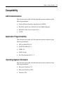
Compatibility....................................................................................... 1‐35
LAN Communications................................................................. 1‐35
Application Programmability..................................................... 1‐35
Operating System Information................................................... 1‐35
vii
Chapter 2: Hardware Installation
Introduction ........................................................................................... 2‐1
Installation Summary..................................................................... 2‐1
Installation Restrictions........................................................................ 2‐2
Installing Peripherals............................................................................ 2‐3
Peripheral Cable Routing .............................................................. 2‐3
Accessing the Cable Connectors................................................... 2‐4
Cable Connector Identification..................................................... 2‐5
PS/2 Keyboard/Mouse Cable Connections ................................. 2‐6
Mouse Installation Restriction.................................................. 2‐6
Installing an NCR 5964 12.1‐inch Touch LCD............................ 2‐7
DVI Cable Connections ............................................................. 2‐8
RS‐232 Cable Connections ........................................................ 2‐9
Installing a 5942 12.1‐Inch LCD Monitor .................................. 2‐10
Installing the Transaction Printer............................................... 2‐11
USB Installation ........................................................................ 2‐11
RS‐232 Installation w/Power from Powered USB................ 2‐12
Installing an NCR 5972 Remote Customer Display................. 2‐13
Tall Post Models ....................................................................... 2‐13
Desktop Models ............................................................................ 2‐14
Cable Connections ................................................................... 2‐15
Installing a Cash Drawer............................................................. 2‐16
Installing a Second Cash Drawer ............................................... 2‐17
Calibrating the Touch Screen ............................................................ 2‐18
Calibration Using MicroTouch (Windows) .............................. 2‐19
Calibration Using Microcal (DOS) ............................................. 2‐21
Summary ................................................................................... 2‐22
Out‐of‐Box Failures ...................................................................... 2‐23
viii
Chapter 3: Setup
Entering Setup ....................................................................................... 3‐1
Keyboard Shortcuts .............................................................................. 3‐1
How to Select Menu Options .............................................................. 3‐3
BIOS Default Values ............................................................................. 3‐4
Main Menu ...................................................................................... 3‐4
Advanced Menu ............................................................................. 3‐4
PCI/PnP Menu ................................................................................ 3‐7
Boot Menu ....................................................................................... 3‐8
Security Menu ............................................................................... 3‐10
Chipset Menu................................................................................ 3‐10
Chapter 4: Operating System Recovery
Introduction ........................................................................................... 4‐1
Prerequisites .................................................................................... 4‐1
Connecting an External CD‐ROM Drive..................................... 4‐2
OS Recovery Procedures ............................................................... 4‐3
Completing the OS Installation .................................................... 4‐5
Windows 2000 ............................................................................ 4‐5
Windows NT 4.0......................................................................... 4‐5
Windows XPe ............................................................................. 4‐5
Gold Disk Contents............................................................................... 4‐6
Microsoft Operating System License Agreements..................... 4‐6
Operating System Restrictions ..................................................... 4‐7
Standby and Hibernate Mode Restriction .............................. 4‐7
NCR 7402 Win2000OS Recovery Software (LPIN: D370‐
0586‐0100) ........................................................................................ 4‐7
Installed Software: ..................................................................... 4‐7
Software Drivers......................................................................... 4‐8
ix
Special Settings ........................................................................... 4‐8
Recommendation ....................................................................... 4‐9
NCR RealPOS 7402 WinNT OS Recovery Software (LPIN: D370‐0587‐0100)............................................................................ 4‐10
Installed Software: ................................................................... 4‐10
Software Drivers....................................................................... 4‐10
Special Settings ......................................................................... 4‐10
Recommendation ..................................................................... 4‐12
NCR 7402 Windows XPe Operating System Recovery Software (LPIN: D370‐0588‐0100).............................................. 4‐13
Installed Software: ................................................................... 4‐13
Software Drivers....................................................................... 4‐13
Special Settings ......................................................................... 4‐14
Recommendation ..................................................................... 4‐14
Chapter 5: BIOS Updating Procedures
Introduction ........................................................................................... 5‐1
Prerequisites .................................................................................... 5‐1
Connecting an External CD‐ROM Drive..................................... 5‐2
Updating Procedures ..................................................................... 5‐3
BIOS Crisis Recovery............................................................................ 5‐5
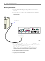
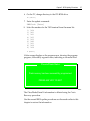
Recovery Procedures...................................................................... 5‐6
Cable/Connector Pin‐Out Information .............................................. 5‐8
Chapter 6: 2x20 Customer Display
Introduction ........................................................................................... 6‐1
General Specifications .......................................................................... 6‐1
Serial Communication Interface ......................................................... 6‐1
Command Codes................................................................................... 6‐2
x
User Defined Character Definition (08h, CODE, Byte1…Byte5).................................................................................. 6‐2
Character Table Select (09h, TABLE CODE) .............................. 6‐3
Clear Display (12h)......................................................................... 6‐3
Luminance Control (11h, LUMINANCE)................................... 6‐3
Cursor Position (10h, POSITION) ................................................ 6‐4
Reset (13h) ....................................................................................... 6‐4
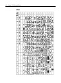
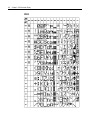
Character Tables and Codes ......................................................... 6‐4
CP437 ........................................................................................... 6‐5
CP858 ........................................................................................... 6‐6
CP866 ........................................................................................... 6‐7
CP932 ........................................................................................... 6‐8
Chapter 7: Cash Drawer Interface
Introduction ........................................................................................... 7‐1
Logic Description .................................................................................. 7‐1
Component Architecture ..................................................................... 7‐4
Code Changes ................................................................................. 7‐4
Hardware/Firmware Interfaces........................................................... 7‐6
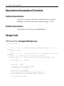
Dependencies/Assumptions/Constraints ........................................ 7‐10
Hardware Dependencies............................................................. 7‐10
Software Dependencies ............................................................... 7‐10
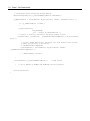
Sample Code ........................................................................................ 7‐10
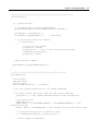
CPP Source File: DarlingtonCDSample.cpp.............................. 7‐10
Header file: DarlingtonCDSample.h........................................... 7‐26
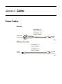
Appendix A: Cables
Printer Cables .......................................................................................A‐1
Scanner Cables......................................................................................A‐3
xi
7872 or 7875 Scanner/Scale (RS‐232) ...........................................A‐3
7892 Scanner (Powered RS‐232) ..................................................A‐3
7882 Scanner (Powered RS‐232) ..................................................A‐3
7837 Scanner (Powered RS‐232) ..................................................A‐3
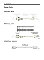
Display Cables......................................................................................A‐4
VGA Display, Mono......................................................................A‐4
VGA Display, Color ......................................................................A‐4
CRT AC Power Extension ............................................................A‐4
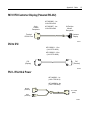
5972 VFD Customer Display (Powered RS‐232) .......................A‐5
DVI to DVI......................................................................................A‐5
PS/2 ‐ RS‐232 & Power ..................................................................A‐5
LCD Power Cable ..........................................................................A‐6
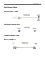
Cash Drawer Cables ............................................................................A‐7
Dual Cash Drawer, Y‐Cable.........................................................A‐7
Cash Drawer, Extension Cable ....................................................A‐7
Communications Cable .......................................................................A‐7
Ethernet, 10/100BaseT ...................................................................A‐7
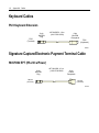
Keyboard Cables ..................................................................................A‐8
PS/2 Keyboard Extension .............................................................A‐8
Signature Capture/Electronic Payment Terminal Cable ................A‐8
5945/5992 EPT (RS‐232 w/Power)................................................A‐8
Power Cables (AC)...............................................................................A‐9
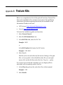
Appendix B: Feature Kits
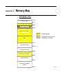
Appendix C: Memory Map
DOS Considerations...................................................................... C‐2
xii
Revision Record
Issue
A Date
Remarks
Nov 2003 First Issue xiii
Radio Frequency Interference Statements
Federal Communications Commission (FCC)
Information to User This equipment has been tested and found to comply with the limits for a Class A digital device, pursuant to Part 15 of FCC Rules. These limits are designed to provide reasonable protection against harmful interference when the equipment is operated in a commercial environment. This equipment generates, uses, and can radiate radio frequency energy and, if not installed and used in accordance with the instruction manual, may cause harmful interference to radio communications. Operation of this equipment in a residential area is likely to cause interference in which case the user will be required to correct the interference at his own expense. NCR is not responsible for any radio or television interference caused by unauthorized modification of this equipment or the substitution or attachment of connecting cables and equipment other than those specified by NCR. The correction of interference caused by such unauthorized modification, substitution or attachment will be the responsibility of the user. The user is cautioned that changes or modifications not expressly approved by NCR may void the userʹs authority to operate the equipment. Canadian Department of Communications
This Class A digital apparatus complies with Canadian ICES‐003. This digital apparatus does not exceed the Class A limits for radio noise emissions from digital apparatus set out in the Radio Interference Regulations of the Canadian Department of Communications. Cet appareil numérique de la classe A est conforme à la norme NMB‐003 du Canada. Le présent appareil numérique nʹémet pas de bruits radioélectriques dépassant les limites applicables aux appareils numériques de la classe A prescrites dans le règlement sur le brouillage radioélectriques édicté par le ministrère des Communications du Canada. Voluntary Control Council for Interference (VCCI)
xiv
Declaration of Conformity
Manufacturer's Name
NCR Corporation Manufacturer's Address
NCR Corporation Retail Solutions Division – Atlanta 2651 Satellite Boulevard Duluth, GA 30096‐5810 Type of Equipment
Information Technology Equipment Model Number
Class 7402 Electrical Ratings (Input)
100‐240 V ac, 6.0 A, 50‐60 Hz NCR Corporation, 1700 South Patterson Boulevard, Dayton, OH 45459, USA, declares that the equipment specified above conforms to the referenced EU Directives and Harmonized Standards. EU Directive
Harmonized Standard(s)
89/336/EEC (EMC) EN 55022 EN 55024 EN 61000‐3‐2 EN 61000‐3‐3 IEC 61000‐4‐2 IEC 61000‐4‐3 IEC 61000‐4‐4 IEC 61000‐4‐5 IEC 61000‐4‐6 IEC 61000‐4‐8 IEC 61000‐4‐11 73/23/EEC (Low Voltage) EN 60950 NCR Corporation Retail Solutions Division — Atlanta 2651 Satellite Boulevard Duluth, GA 30096‐5810 Chapter 1: Product Overview
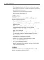
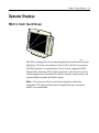
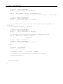
Introduction
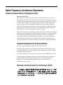
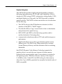
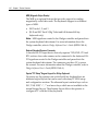
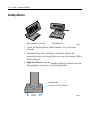
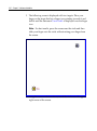
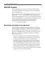
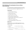
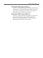
NCR’s RealPOS 70 (also referred to as NCR 7402) is a scalable, retail‐
hardened Point‐of‐Sale Solution with an intuitive touch screen interface designed for extended life cycles, stability, and superior availability. Engineered to thrive in the most demanding environments, the RealPOS 70 offers leading retailers in Hospitality, Convenience Stores and General Merchandise a POS platform that offers the greatest value for their POS investment. Unlike other POS solutions, the RealPOS 70 sets a new standard by offering an unprecedented combination of standard features including new embedded technology, tool‐free serviceability, and maximum configuration flexibility. Magnetic Stripe Reader
Power Switch
20950
1-2
Chapter 1: Product Overview
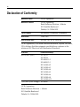
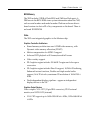
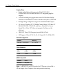
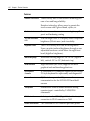
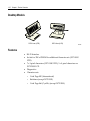
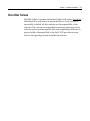
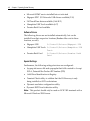
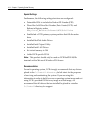
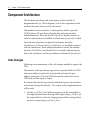
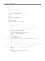
Hinged LCD
The RealPOS 70 utilizes a top‐hinged LCD which allows extremely quick and easy motherboard access. The LCD can be completely removed if necessary for upgrades or repair. Functioning much like the hood of a car to gain access to the engine, the LCD has a security mechanism allowing it to be locked into place if desired. 20932
Chapter 1: Product Overview
1-3
Hardware Options
•
Integrated 3‐Track ISO MSR •
Integrated Stereo Module •
Integrated Infrared Sensor •
PCMCIA (for wireless LAN) •
128 MB, 256 MB, 512 MB non‐ECC Memory DIMMs •
256 MB Compact Flash •
Cash drawers •
•
•
•
•
−
2183 Mid‐Size Cash Drawer (modular) −
2189 Full‐Size Cash Drawer (modular) −
Dual cash drawer cable MSR −
ISO −
JIS Keyboard −
USB Alphanumeric Big Ticket Keyboard −
PS/2 Alphanumeric Big Ticket Keyboard Customer Displays −
Integrated 2 x 20 VFD −
International APA (All Points Addressable) Printers −
7167 Thermal Receipt/Impact Printer −
7197 Thermal Receipt Printer Integrated PCMCIA Slot Adapter Board (Two Type 2 Slots): PCI I/F 1-4
Chapter 1: Product Overview
•
PCMCIA Wireless Adapter Supporting 802.11 Standard •
12‐Inch LVDS TFT Display – Dual Bulb Enhanced Brightness •
3M Touch Systems Resistive or Capacitive Touch Sensor •
Low‐Profile ATX Power Supply – 300 Watts Operating Systems
•
DOS 6.22 (7402‐3xxx) •
Windows NT Workstation •
Windows 2000 Professional •
Windows XPe •
Windows XP (certified) •
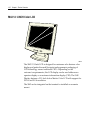
Linux (certified) Removable Motherboard Sled
Complementing the hinged LCD is a motherboard tray mounting mechanism which allows the component to be easily removed without the use of tools. Removable Power Supply
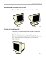
The 7402 utilizes an intuitive removable rear cover allowing easy access to the power supply. The Power Supply is mounted on a sled which permits removal or tool free service. Removable Hard Disk
Removal of the back cover permits easy removal of the front cover, which permits tool‐free removal of the hard disk. Chapter 1: Product Overview
1-5
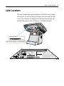
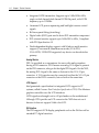
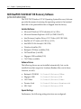
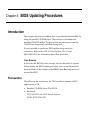
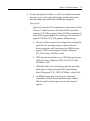
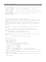
Label Locations
The serial number and model number are included on three labels, which can be viewed by tilting the display and removing the cable cover. If the terminal was shipped with an Operating System pre‐
installed then there is also a Certificate of Authenticity label. Class:7402-1000
S/N:36309845
Date:21 November 2003
Unit Serial:36309845
NCR Corp Class:7402-1000
NCR Corporation
c.
o
xxxx-xx-xxxx(x)c
US
Model No
me
Serial No
NYCE
NO.
437
Atlanta, GA 30096
Class 7402
he
Date of Mfg.
: 7402
: 36-309845
: 21 NOV 2003
NCR
This device complies
with Part 15 of the FCC rules.
100-120 V~ac,
Operation is subject to the following
50-60 Hz 6A 300W two conditions:
(1) this device may not cause harmful
interference,and
200-240 V~ac,
(2) this device must accept any interference received,
50-60 Hz 3A 300W including interference that may cause undesired operation.
This Class A digital apparatus complies with Canadian ICES-003.
PS
Cet appareil numerique de la classe A est
conforme a la norme NMB-003 du Canada.Patents Pending
E
M E 01
Made in Singapore
VCCI-A
20946
1-6
Chapter 1: Product Overview
Model Numbers
The following table identifies 7401 terminal models. Major Model
CPU
7402‐1000 Intel 2.0 GHz Celeron, Resistive Touch, 128MB Memory, 40GB Hard Disk, 3 RS‐232, 3 Powered USB, 2 Standard USB, Audio/Mic. and US Power Cord, No MSR, No Customer Display, Integrated Stereo Speakers 7402‐1010 Intel 2.0 GHz Celeron, Capacitive Touch, 256MB Memory, 40GB Hard Disk, 3 RS‐232, 3 Powered USB, 2 Standard USB, Audio/Mic. and US Power Cord, MSR, No Customer Display, Integrated Stereo Speakers Chapter 1: Product Overview
1-7
Hardware Modules
Pentium 4 Embedded ATX Motherboard
•
Celeron 2.0 GHz with 400 MHz Front Side bus •
Intel Montara‐GML (852GM) North Bridge with integrated LVDS and multi‐monitor capability •
Inverter & LCD power support •
LCD Adapter Board •
DVI or VGA Interfaces for Secondary Displays •
DDR‐SDRAM; 266MHz in desktop DIMM, 2 sockets (1GB Max) •
Intel ICH4 Desktop South Bridge •
USB 2.0, supports 6 ports, including 2 USB+Power (12V), 2 internal USB •
ATA‐100 Primary & Secondary IDE Ports •
Intel Integrated 10/100 Ethernet •
Three Serial Ports, all with 12V Power Option •
Support for Internal Wedge Peripherals (MSR) •
PCI Connector Supporting a Riser Card •
CPU and Power Supply Fan Speed Detection •
Integrated Audio with Amplified Speaker Output and Mic Input, Internal PC Speaker •
IRDA Interface •
Daughter Card GPIO Interface for Cash Drawer and Retail Function Support •
AMI BIOS with NCR Retail Customizations and ACPI support 1-8
Chapter 1: Product Overview
Retail Daughter Card
•
Cash Drawer Port (supports two drawers via a Y‐cable) •
Touch Controller (3M EXII) for Resistive & Capacitive Touch Sensors •
NCR 2nd Generation Trigantor MSR Controller with Wedge I/F •
24 V Powered USB Port •
Motion Sensor I/F Other Hardware Features
•
Integrated PCMCIA slot adapter board (Two type 2 slots): interfaces via PCI •
PCMCIA wireless adapter supporting 802.11 standard •
12 inch LVDS TFT display – dual bulb enhanced brightness •
3M Touch Systems resistive or capacitive touch sensor •
Internal Compact Flash adapter Chapter 1: Product Overview
1-9
Hardware Module Descriptions
Motherboard
Processor/Chip Set
The terminal uses an Intel architecture processor, which permits it to leverage existing software drivers and applications, as well as provide the greatest flexibility in choosing an operating system. This provides several other advantages: •
Capable of SW MPEG‐1 or MPEG‐2 playback at 30 frames per second with 22 kHz stereo audio (may be limited by OS constraints). •
SoundBlaster®‐compatible audio •
Expansion capabilities for optional features and future requirements (PCI bus and USB) The following identifies processors, system bus speed, and on‐board memory available on the board: •
Intel 2.0 GHz Celeron Processor •
128kB L2 Cache •
400 MHz front side bus Montara-GML GMCH (852GM Graphics & Memory Controller Hub)
•
Supports CPU with 400 MHz FSB •
Supports Desktop Intel Celeron or Pentium 4 processor with Northwood Core •
Memory: DDR‐DRAM 200 or 266MHz, up to 2 double sided DIMMs, No ECC Support, 1GB maximum •
Integrated graphics with VGA, LVDS LCD, and 1 digital video (DVO) port 1-10
Chapter 1: Product Overview
•
Dual independent display with Windows multi‐monitor support •
Shared memory architecture – 8‐32 MB video memory dynamically allocated from system memory •
Hub interface to ICH4 south bridge at 266 Mb/s •
IOQD (In order Queue Depth) = 12 South Bridge Features
The 7402 Motherboard uses the Intel ICH4 South Bridge, which provides the following functions: •
Integrated Intel Audio (requires external codec) •
Integrated 10/100 Ethernet controller (requires external 82562 PHY transceiver chip) •
IDE controller with Primary & Secondary channels, each supporting master & slave drives; ATA‐100 support •
USB Host controller – Four USB host controllers, six physical USB ports, USB 2.0 supported •
PCI Bus Host Controller – up to 6 bus masters supported •
LPC Bus Bridge Controller – interface to SuperIO & Trusted Platform Module •
Hub Interface to North Bridge at 266Mb/sec •
SMBUS (I2C) Controller – Interface Hardware monitor •
Firmware Hub (BIOS ROM) Interface •
ACPI Power management support •
Base PC functionality: DMA controller, Interrupt controller, Real‐
Time‐Clock, and event timer Video Memory
Shared memory architecture uses 8‐64 MB video memory, with Dynamic video memory allocation (DVMT). Chapter 1: Product Overview
1-11
BIOS Memory
The 7402 includes 512KB of Flash BIOS and 1MB size Flash parts. A DMI area in the BIOS ROM stores system information about the 7402, such as serial number and model number. Platform software detects board version via device ID of key components on the board. There is no board ID EEPROM. Video
The 7402 uses integrated graphics in the Montara chip. Graphics Controller Architecture
• Shared memory architecture uses 8‐32MB video memory, with Dynamic video memory allocation (DVMT) •
Motion compensation for MPEG‐2 support •
Software DVD playback at 30 frames/second full screen •
Video overlay support •
2D Graphics engine includes 128 bit BLT engine and color space conversion •
3D Graphics engine includes DirectX support, 16/24 bit Z‐buffering, Enhanced texture functions, Double and triple render buffer support, 16 & 32 bit color, maximum 3D resolution of 1600x1200 @ 85Hz •
Dual independent display pipelines – appear as independent display devices to the OS Graphics Output Devices
Video outputs: VGA CRT (15 pin DB‐9 connector), DVI‐I external monitor, and LVDS LCD (internal) •
VGA CRT support up to 1600x1200x24 bit @ 85Hz, 1920x1440x24 bit @ 60Hz 1-12
Chapter 1: Product Overview
•
Integrated LVDS transmitter: Supports up to 1400x1050@ 60Hz single or dual channel dual channel LVDS flat panel, with LVDS frequency up to 112MHz. •
Generates LCD power sequencing and backlight inverter control signals •
Bi‐Linear panel fitting (stretching) •
Digital video (DVO) port used to drive DVI transmitter component •
DVI external monitor support up to 1600x1200 @ 60Hz, Compliant with DVI Specification 1.0 •
Dual independent display support with Windows multi‐monitor support (Concurrent & Simultaneous modes) VGA+DVI, VGA+LVDS, LVDS+DVI supported, any device can be selected as primary. Analog Monitor
DVI‐I is provided as a convenience for users with analog monitors having a DVI connector. DVI‐I means an analog VGA signal is present on the DVI connector, along with the digital DVI signals. On the 7402, the analog DVI‐I signal is the same as that sent to the VGA 15 pin connector. A VGA monitor may be connected to either the VGA 15 pin connector or the DVI‐I connector, but not both at the same time. LCD Support
Intel generated a specification for integrated LCD support in PC systems, called Common Panel Interface Specification (CPIS). The Montara graphics controller uses the LCD interfaces. LVDS signals are brought out to a 50 pin header on the motherboard. Although CPIS specifies an LCD connector the 7402 does not use it because it does not support 24‐bit color LCD. DVI Interface
The DVI supports NCR display peripherals such as the 5964 as well as standard PC digital monitors. Chapter 1: Product Overview
1-13
Power Management
The BIOS supports the ACPI 1.1 specification. This permits the terminal to go to a low power state during some level of inactivity. With ACPI, the operating system has some control over the power management by going into suspend, standby, or hibernate (depending on the Operating System). The S0, S1, and S5 states are implemented. For the detail of the ACPI, refer to ACPI Specification 2.0b. Not all Entry and Exit points are available at all times. Availability is based on ACPI states. Notes:
•
•
Supported wakeup methods include: –
Wake on Alarm can be used in standby (S1) or soft off (S5) states. –
Wake on LAN is supported from S1 only. –
Wake on ring indicator is functional from S1 and S5. –
Motion Sensor allows wakeup from S1 standby based on activity near the system Keyboard, Mouse, or USB activity as supported by the Intel chipset USB devices must be enabled in Windows for Wake from Standby to function. This is set in at: Start Æ Control Panel Æ System Æ Hardware Tab Æ Device Manager Æ [USB device] Æ Properties. There is a check box to enable the function under the USB tab. 1-14
Chapter 1: Product Overview
Cash Drawer Support
The 7402 Terminal can control a cash drawer through a cash drawer Kickout connector on the back of the terminal (daughter card), or through the cash drawer Kickout connector on the transaction printer. The terminal can be configured with 0, 1, or 2 cash drawers. The first drawer is attached to the terminal through a cable with an RJ‐45 connector. A second drawer can be connected using a ‘Y’ cable. Note: A single Open/Close status signal is shared with both drawers. Therefore, it is not possible to determine which cash drawer is open. Power LED
The Processor Board provides support for an external green power LED through the onboard Front Panel. This LED reflects the state of the system power supply. The LED is turned on anytime the power supply is fully on, which occurs when the system is on or in standby. The power LED cannot be controlled by software. When the system is in standby or in a screen saver, the power LED notifies the user that the system is powered on and can quickly return to a normal working state. MSR
The MSR interface supports a maximum of 3 tracks of magnetic stripe information for support of ISO format cards. Activate the MSR interface by enabling it in BIOS Setup under IO Configuration. The MSR interface controller is a memory‐mapped device, which can reside at system memory addresses CA000, CC000, or D0000. If MSR capability is not desired, it may be disabled through BIOS Setup. Chapter 1: Product Overview
1-15
Graphics Subsystem
The GMCH IGD provides a highly integrated graphics accelerator delivering high performance 3D, 2D, and video capabilities. With its interfaces to UMA using a DVMT configuration, analog display, LVDS, and digital display (e.g. flat panel), the GMCH provides a complete graphics solution. The GMCH contains an extensive set of instructions for the following: •
The GMCH also provides 2D hardware acceleration for block transfers of data (BLTs). The BLT engine •
Provides the ability to copy a source block of data to a destination and perform raster operations (e.g., •
ROP1, ROP2, and ROP3) on the data using a pattern, and/or another destination. Performing these •
common tasks in hardware reduces CPU load, and thus improves performance. •
High bandwidth access to data is provided through the System Memory ports. The GMCH uses Tiling architecture to increase System Memory efficiency and thus maximize effective rendering bandwidth. Intel DVMT (Dynamic Video Memory Technology) permits the graphics driver to use only the exact amount of system memory required for the current graphics state. Excess memory is returned to the operating system. The driver allocates memory in the range of 8 ‐ 64MB for video. Under DOS, the BIOS setting for video memory takes effect. Up to 48MB is permitted, but normally the default value of 8MB is acceptable. 1-16
Chapter 1: Product Overview
Graphics Driver
• Single, unified driver that supports all Intel® 830, 845G, 852GM/GME, 855GM/GME, and 865G/GV integrated graphics chipsets •
CUI API for third party application control of Windows display attributes via the Monitor Control Command Set (MCCS) standard •
Backlight Image Adaptation support for Intel® 855GME chipset •
OS Support: Windows XP, XP Media Center Edition, XP Tablet PC Edition, 2000, ME, NT4, 98 SE, and Linux Xfree86 4.0.x Server, Kernel 2.4.x. (Note: NCR does not support all of these on the platform). •
IBM OS/2 Warp 3.0/4.0 support provided by SciTech •
API Support: Direct X 7.0, 8.0, 8.1, 9.0 OpenGL 1.3, GDI & GDI+ Resolutions Supported
Resolution
Max Vfreq
640x480 – 1024x1280 60 – 85 Hz Colors Supported
256 Colors
(8-Bit)
65,000 Colors
(16-Bit)
16.7 M Colors
(24-Bit)
512 k 1 MB 2 MB NCR 12.1 inch LCD
Resolution
Colors
800x600 262,144 Note: In BIOS POST and DOS modes the LCD image is stretched to fill the display. Intel Graphics driver also permits stretching. Chapter 1: Product Overview
1-17
Dual Displays
The Summa II Motherboard (Release 2.5) is dual display (LCD and CRT) capable. In a dual display environment the 7401 terminal supports 16‐bit color when both displays are connected to the motherboard. Both displays must have the same maximum resolution capability. Refer to the following information for details about the implementation of a dual display configuration. •
Lynx Family Control Panel Specification 1.2 on the NCR 74xx Base System and Client Third party Drivers CD‐ROM (Product ID: D370‐0111‐0100) or in the video.exe self‐extracting Video Drivers file on the Retail Solutions Specific Third Party Products Drivers and Patches web site at: http://www.ncr..com/support/support_drivers_patches.asp?Class=retail_TPP. •
Retail Customer Information Display User’s Guide (BD20‐1431‐B) on the NCR Information Products web site at: http://www.info.ncr.com/eHome.cfm 1-18
Chapter 1: Product Overview
Printer Options
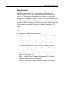
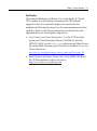
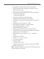
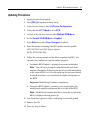
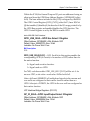
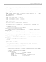
NCR 7167 Printer
The NCR 7167 Printer is a fast, quiet, relatively small and very reliable multi‐function printer. It prints receipts, validates and prints checks, and prints on a variety of single or multiple part forms. There is not journal as it is kept electronically by the host terminal. The printer can connect through a USB port or a serial port. It can receive power from a power supply or through a USB+ power cable. Power Supply
AC Adapter Cable
19711a
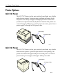
NCR 7197 Printer
The NCR 7197 Printer is a fast, quiet, relatively small and very reliable multi‐function printer. It prints receipts and two‐color printing. The printer can connect through a USB port or a serial port. It can receive power from a power supply or through a USB+ power cable. Power Supply
AC Adapter Cable
19712a
Chapter 1: Product Overview
1-19
Operator Displays
5964 12.1-Inch Touch Screen
The 5964 is designed for touch‐based applications and features a high‐
brightness 12.1‐Inch Active Matrix Color LCD with SVGA resolution. The 5964 features a 5‐wire Resistive Touch Screen, integrated MSR, Digital Video Interface (DVI), table top mount with tilt and swivel (or can be integrated on the terminal), and convenient connections for an external keyboard and hand held scanner. 19429
Note: If Simultaneous Mode is used (same display on both the integrated LCD and the 5964) then Extended desktop (concurrent mode) is recommended. 1-20
Chapter 1: Product Overview
Features
Resistive Touch Screen
Touch overlay uses 5‐wire resistive technology for ease of use and long reliability. Resistive technology allows users to operate the touch screen with a gloved hand, stylus, etc. Retail Hardened
Touch screen surface contains an anti‐glare, spill‐
proof and hardening coating 12.1-Inch Active Matrix
LCD
Dual backlight color LCD display offers exceptional brightness (300 nits max.) and viewability. Brightness Control
The LCD is factory set to run at full brightness. Users can select reduced brightness through a user adjustable hardware switch below the right front bezel (high/low brightness). Wide Viewing Angle
Horizontal viewing angle of –60° to +60° (right to left), vertical –50° to +50° (bottom to top) SVGA Resolution
High resolution (800 x 600) supports the latest graphical and multimedia applications PS/2 Keyboard
Connector
A convenient PS/2 connector supports a non‐wedge PC‐style keyboard for alpha entry and diagnostics Scanner Connector
RJ‐45 interface provides 5 V power and communication for the NCR RS‐232 hand‐held scanner Tone Speaker
Sounds error tones & audible feedback during operator input ‐ controlled by TAPS/OPOS commands DVI Video Interface
Industry standard DVI (Digital Video Interface) for connection to DVI‐I connector on 7402 RS-232 Touch Interface
7402 Powered RS‐232 connector provides power Chapter 1: Product Overview
1-21
and touch interface for NCR 5964 display Wedge Controller
Passes data (MSR, scanner, keyboard) to host terminal through PS/2 data stream via Y‐cable Terminal Powered
No additional power cord or power supply is required simplifying cable management MSR Option
Integrated 3‐track ISO MSR Tilt / Swivel
The remote table top pedestal mount supports tilt and swivel to adjust display to optimum angle 1-22
Chapter 1: Product Overview
5942 12.1-INCH Color LCD
19809
The 5942 12.1‐Inch LCD is designed for customers who desire a color display and prefer the small footprint and ergonomic packaging of LCD technology versus traditional CRT’s. Depending on the customer’s requirements, this LCD display can be used either as an operator display or a customer information display (CID). The 5942 Display features a 12.1‐Inch Active Matrix Color LCD with support for SVGA and XGA resolution. The 5942 can be integrated on the terminal or installed on a remote mount. Chapter 1: Product Overview
1-23
7452-K309/K404 9-Inch Monochrome CRT
The 9‐Inch CRT can be integrated on the terminal or installed on a remote mount. 7452-K309
7452-K404
19742a
7452-K419 15-Inch Color CRT
The 15‐Inch CRT can be integrated on the terminal or installed on a remote mount. Note: The 15‐Inch display is too large for the Swivel Arm. For integrated configurations it is placed on the Large Peripheral Extension Deck, which is included in the Integration Tray Accessories Kit (7402‐K310/K315). 19743
1-24
Chapter 1: Product Overview
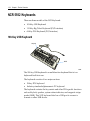
NCR 5932 Keyboards
There are three models of the 5932 Keyboard: •
109‐Key USB Keyboard •
115‐Key Big Ticket Keyboard (PS/2 interface) •
68‐Key POS Keyboard (PS/2 interface) 109-Key USB Keyboard
Keylock
MSR
19586
The 109‐key USB keyboard is a multifunction keyboard that is two keyboards built into one. The keyboard consists of two major sections: •
38‐key POS keyboard •
Industry‐standard alphanumeric PC keyboard The keyboard contains the key matrix and other POS‐specific functions such as Keylock, speaker, system status indicator, and magnetic stripe reader (MSR). This 5932 keyboard also has a USB port to connect a Scanner or other USB device. Chapter 1: Product Overview
1-25
Features
The NCR 5932 USB Keyboard supports the following features: •
Keylock •
Speaker •
Magnetic Stripe Reader (MSR) •
Keyboard Status LEDs Keylock
The USB keyboard has a four‐position Keylock. You can rotate the Keylock between specific positions by use of three keys. The positions are explained in the following table. Abbreviation Position
Description
Ex Exception Used by the customer or service representative to perform low level programming such as workstation diagnostics, configuring the workstation, or loading the workstation. L Locked Used to lock keyboard input to prohibit use of normal functions. R Register Used when performing normal retail mode functions. S Supervisor Used by the supervisor to provide highest level of workstation control in cases such as refunds and running totals. Speaker
The programmable speaker is capable of generating key clicks and error tones. 1-26
Chapter 1: Product Overview
MSR
The MSR is an optional feature that provides support for reading magnetically coded data cards. The keyboards support two different types of MSR: •
ISO Tracks 1, 2, and 3 •
JIS‐II and ISO Track 2 Keyboard Status LEDs
The keyboard has three status LEDs: •
Num Lock •
Caps Lock •
Scroll Lock These features are used to provide the present state of the keyboard. The indicators are single color (Green) LED’s. When the system is off, no LED’s are illuminated. Chapter 1: Product Overview
1-27
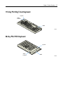
115-Key PS/2 Big Ticket Keyboard
Keylock
Status
Indicator
MSR
19745
68-Key PS/2 POS Keyboard
Keylock
Status
Indicator
MSR
19746
1-28
Chapter 1: Product Overview
Features
The 5932 PS/2 Keyboards include the following features: •
Keylock •
Speaker •
System Status Indicator LED •
Magnetic Stripe Reader (MSR) •
External Decoded Scanner Connector •
Special PC Setup mode on the 68‐key keyboard The operations of the user‐programmable speaker, Magnetic Stripe Reader (MSR), keylock, and scanner connector are handled by the Wedge controller. Please refer to the Wedge Software Userʹs Guide (BD20‐1368‐A) for detailed information about interfacing and configuring these devices. Keylock
The Big Ticket and 68‐key keyboards have a four‐position keylock switch. The positions are explained in the following table. Abréviation Position
Description
Ex Exception Used by the customer or service representative to perform low‐level programming such as terminal diagnostics, configuring the terminal, or loading the terminal. L Locked Used to lock keyboard input to prohibit use of normal functions. R Register Used when performing normal retail mode functions. S Supervisor Used by supervisor to provide highest level of terminal control in cases such as refunds and running totals. Chapter 1: Product Overview
1-29
Speaker
A programmable speaker generates key clicks and error tones. Buzzer
The buzzer is an internal on board Buzzer. System Status Indicator LED
The system status indicator is a two‐color LED. The green color indicates the keyboard is powered. Red indicates an error condition. When the system is off, the LED is extinguished. When the 68‐key keyboard is in the special ʺPC setupʺ mode, the LED flashes red/green. The status and condition indicated by the LED are shown as follows: Status
Condition
Green Power on Red Wedge controller reporting an error condition Flashing red/green Keypad of 68‐key keyboard in ʺPC Setupʺ mode (See special keypad mode on next page) Off System off Note: For more information about the Wedge controller, refer to Wedge Software Userʹs Guide (BST0‐1368‐B). 1-30
Chapter 1: Product Overview
MSR (Magnetic Stripe Reader)
The MSR is an optional feature that provides support for reading magnetically coded data cards. The keyboards support two different types of MSR: •
ISO Tracks 1, 2, and 3 •
JIS‐II and ISO Track 2 (Big Ticket and full‐featured 68‐key keyboards only) Note: MSR signals are routed to the Wedge controller and passed into the system keyboard data stream. For more information about the Wedge controller, refer to Wedge Software Userʹs Guide (BD20‐1368‐A) External Decoded Scanner Connector
A decoded RS‐232 input device that only requires TXD, RXD, CTS and RTS, such as a bar‐code scanner, can be connected to the keyboard. RS‐
232 signals are routed to the Wedge controller and passed into the system keyboard data stream. The connector provides +5V to power the scanner. For more information about the Wedge controller, refer to Wedge Software Userʹs Guide (BD20‐1368‐A). Special "PC Setup" Keypad Layout for 68-key Keyboard
On power‐up, the operator can switch the 68‐key keyboard into an alternate keypad layout that can be used with many PC BIOS setup and configuration routines. The alternate layout contains keys such as ESC, TAB, END, ʺ+ʺ, ʺ‐ʺ and arrow keys which are not available in the normal keypad layout. The alternate layout allows the operator to configure a PC with the 68‐key keyboard. Chapter 1: Product Overview
1-31
NCR 5972 2x20 Remote Customer Display
Tall Post Models
5972-1xxx (VFD)
5972-2xxx (LCD)
19750a
1-32
Chapter 1: Product Overview
Desktop Models
5972-1xxx (VFD)
5972-2xxx (LCD)
19749
Features
•
RS‐23 Interface •
Socket for 32K of PROM for additional character sets (5972‐1000 VFD). •
7 x 9 pixel characters (5972‐1000 VFD); 5 x 8 pixel characters on 5972‐2000 LCD •
Diagnostics •
Character sets: –
Code Page 850 (International) –
Katakana (except 5972‐2000) –
Code Page 866 (Cyrillic) (except 5972‐2000) Chapter 1: Product Overview
1-33
NCR 5973 2x20 International VFD Customer Display
Desktop Model
16-Inch Post
Features
•
256x64 dots graphic VFD •
Micro‐controller •
Flash ROM •
Display driver circuitry •
Communication/power connector •
Power converter circuitry •
Communication drivers •
Bi‐directional parallel interface support 20448
1-34
Chapter 1: Product Overview
System Configuration Diagram
CRT
5964
Touch Screen
5942
DVI RS-232
(Powered)
RS-232
VGA
USB
(24 V)
7167
7197
Retail
Daughter
Card
5932 USB
Cash
Drawer
2nd Drawer (Y-Cable)
2189/2183
PS/2
5932 Big Ticket
Mouse
5972-2xxx
RS-232
USB
(12 V) USB
RS-232
(Powered)
7882
7162
7197
7875
PS/2
Parallel
RS-232 Peripherals (Powered)
RS-232 Peripherals
5972-1xxx
LAN
7402 Motherboard
7167
5945
5992
7892
7837
20929
Chapter 1: Product Overview
Compatibility
LAN Communications
The software associated with the terminal systems conform to the following standards: •
Network Driver Interface Specification (NDIS 4) •
IEEE 802.3 & 802.3u CSMA/CD (10/100 MB/s Ethernet) •
IEEE 802.2 Link Level Control (LLC) •
TCP/IP Application Programmability
The software associated with the terminal systems conform to the following standards: •
OLE for Retail POS 1.4 •
JavaPOS for Retail 1.4 •
HTML 4.0 •
ECMA Script •
Java Development Kit 1.1.3 Operating System Information
The software associated with the terminal systems conform to the following standards: •
Microsoft Windows NT •
Microsoft Windows 2000 •
Windows XPe 1-35
Chapter 2:
Hardware Installation
Introduction
The 7402 is fully assembled at the factory. This chapter explains how to connect optional hardware components to these terminals. Installation Summary
The terminal should be removed from the shipping packaging and visual checks made to verify the correct hardware configuration. The system is then configured and any communication cables are connected. Only after inspection should the power cord be attached to the system and then connected to the AC power source. Power‐up self‐tests will run to verify basic functionality. Power Cord
21047 ROM‐based setup should be used to configure network options. Full configuration depends upon the system server and the management web site. 2-2
Chapter 2: Hardware Installation
Installation Restrictions
•
Before installing the terminal, read and follow the guidelines in the NCR RealPOS 72 Site Preparation Guide (B005‐0000‐1464) and the NCR Workstation and Peripheral AC Wiring Guide (BST0‐2115‐53). •
Install the terminal near an electrical outlet that is easily accessible. Use the power cord as a power‐disconnect device. •
Do not permit any object to rest on the power cord. Do not locate the terminal where the power cord can be walked on. •
Use a grounding strap or touch a grounded metal object to discharge any static electricity from your body before servicing the terminal. •
If the power cord is replaced, it must be replaced with the same type of cord with the protective shroud. •
Do not route the power cord through openings with sharp edges. Caution: This unit contains hazardous voltages and should only be serviced by qualified service personnel. Caution: DO NOT connect or disconnect the transaction printer while the terminal is connected to AC power. This can result in system or printer damage. Chapter 2: Hardware Installation
2-3
Installing Peripherals
Peripheral Cable Routing
The peripheral cables are routed down through the base and out the rear of the unit. They are secured internally with a Cable Clamp. Cable Clamp
21025
2-4
Chapter 2: Hardware Installation
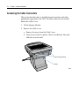
Accessing the Cable Connectors
This section describes how to install transaction printers and other peripherals supported by the 7402. The cable connectors are located behind the Cable Cover. 1. Tilt the Display Module. 2. Remove the Cable Cover. a. Remove the screw from the Cable Cover. b. Press down on the two plastic Cable Cover Release Tabs and slide the cover forward. Front Cover Latches
Screw
20931
Chapter 2: Hardware Installation
2-5
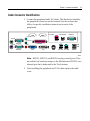
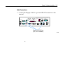
Cable Connector Identification
1. Connect the peripheral and LAN cables. The illustration identifies the peripheral connectors on the terminal. See the sections that follow for specific installation instructions for each of the peripherals. 24V USB
Cash Drawer
RS232/4
Line In
Mouse
Line Out
Kybd
RS232/2
Parallel
Mic
USB
USB
RS232/1
CRT
DVI
LAN
12V USB 12V USB
20917
Note: RS232/1, RS232/2, and RS232/4 can be powered ports. They are enabled via hardware straps on the Motherboard. RS232/3 is an internal port that is dedicated to the Touch feature. 2. After installing the peripheral and LAN cables replace the cable cover. 2-6
Chapter 2: Hardware Installation
PS/2 Keyboard/Mouse Cable Connections
The 7402 has dedicated PS/2 connectors to support both a keyboard and mouse. 24V USB
Cash Drawer
RS232/4
Line In
Mouse
Line Out
Kybd
RS232/2
Parallel
Mic
USB
USB
RS232/1
CRT
DVI
LAN
12V USB 12V USB
PS/2 Mouse
(Green)
PS/2 Keyboard
(Purple)
21028
Mouse Installation Restriction
If you are running Windows NT you must make the following Registry entry in order to enable the Mouse Class Driver. [HKEY_CURRENT_CONFIG/System/CurrentControlSet/Enum/ROOT/
LEGACY_MOUSCLASS/0000]
”CSConfigFlags”=dword:00000000
Chapter 2: Hardware Installation
2-7
Installing an NCR 5964 12.1-inch Touch LCD
The NCR 5964 can be connected as a remote device. 19429a
Note: A PC keyboard is required to configure a 5964 12.1‐inch Touch LCD. The following illustrations show the cable connections for the 5964 and the 7402. There are two cables required. •
DVI Cable – provides the video interface to the 5964 •
RS‐232 Y‐Cable – provides a serial interface and power to the 5964. It also connects the 5964 PS/2 keyboard connector to the terminal, which provides an interface for the wedge controller (MSR, PS/2 Keyboard, Scanner, and Tone Speaker). 2-8
Chapter 2: Hardware Installation
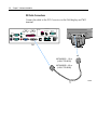
DVI Cable Connections
Connect the cable to the DVI Connectors on the 5964 display and 7402 terminal. 24V USB
Cash Drawer
RS232/4
Line In
Mouse
Line Out
Kybd
RS232/2
Parallel
Mic
USB
USB
RS232/1
CRT
DVI
LAN
12V USB 12V USB
DVI
DVI
497-0422831 - 1.0 m
(1416-C723-0010)
497-0422832 - 4.0 m
(1416-C723-0040)
21029
Chapter 2: Hardware Installation
2-9
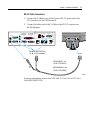
RS-232 Cable Connections
1. Connect the Y‐cable to one of the Powered RS‐232 ports and to the PS/2 connector on the 7458 terminal. 2. Connect the other end of the Y‐Cable to the RS‐232 connector on the 5964 display. 24V USB
Cash Drawer
RS232/4
Line In
Mouse
Line Out
Kybd
RS232/2
Parallel
Mic
USB
USB
RS232/1
CRT
DVI
LAN
12V USB 12V USB
Powered RS-232 Ports
(A, B, or D if available)
RS-232
PS/2
497-0422833 - 1m
(1416-C725-0010)
497-04228324 - 4m
(1416-C725-0040)
21030
For more information refer to the NCR 5964 12.1‐Inch Touch LCD Userʹs Guide (B005‐0000‐1324) 2-10
Chapter 2: Hardware Installation
Installing a 5942 12.1-Inch LCD Monitor
The NCR 5942 can be connected as a remote device. 24V USB
Cash Drawer
RS232/4
Line In
Mouse
Line Out
Kybd
RS232/2
Parallel
Mic
USB
USB
RS232/1
DVI
CRT
VGA
LAN
12V USB 12V USB
Powered USB
VGA
Power
497-0426160 - 4 m Beige
(1416-C803-0040)
497-0428512 - 4 m Black
(1416-C851-0040)
21031
1. Connect the LCD Cable to the VGA connectors on both the 5942 monitor and 7458 terminal. 2. Connect the Power Cable to the 5942 and to a Powered USB connector on the 7458 terminal. For more information refer to the NCR 5942 12.1‐Inch LCD Monitor Userʹs Guide (B005‐0000‐1394) Chapter 2: Hardware Installation
2-11
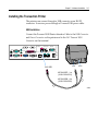
Installing the Transaction Printer
The printers can connect through a USB connector or an RS‐232 connector. It receives power through a Powered USB power cable. USB Installation
Connect the Powered USB Printer Interface Cable to the USB Connector and Power Connector on the printer and to the 24 V Powered USB Connector on the terminal. 24V USB
Cash Drawer
RS232/4
Line In
Mouse
Line Out
Kybd
RS232/2
Parallel
Mic
USB
USB
RS232/1
CRT
DVI
LAN
12V USB 12V USB
USB
24V USB
Power
497-0418587 - 1 m
(1416-C640-0010)
497-0418588 - 4 m
(1416-C640-0040)
21032
2-12
Chapter 2: Hardware Installation
RS-232 Installation w/Power from Powered USB
1. Connect the RS‐232 Printer Interface Cable to the RS‐232 Connector on the printer and to an RS‐232 Connector on the terminal. 2. Connect the Printer Power Cable to the Power Connector on the printer and to the 24 V Powered USB Connector on the terminal. 24V USB
Cash Drawer
RS232/4
Line In
Mouse
Line Out
Kybd
RS232/2
Parallel
Mic
USB
USB
RS232/1
CRT
DVI
LAN
Power
9-Pin to 9-Pin
497-0408349 - 0.7 m
(1416-C266-0007)
497-0407943 - 4 m
12V USB 12V USB
497-0422292 - 4 m
(1416-C712-0040)
RS-232
RS-232
(1416-C266-0040)
497-0409379 - 15 m
(1416-C266-0150)
9-Pin to 25-Pin (7162)
497-0407427 - 1.0 m
(1416-C337-0010)
497-0407429 - 4 m
(1416-C337-0040)
497-0407430 - 15.2 m
(1416-C337-0152)
21033
Chapter 2: Hardware Installation
2-13
Installing an NCR 5972 Remote Customer Display
There are two models of the NCR 5972 Remote Customer Display: •
5972‐1xxx Vacuum Fluorescent Display (VFD) •
5972‐2xxx Liquid Crystal Display (LCD) Tall Post Models
5972-1xxx (VFD)
5972-2xxx (LCD)
19750b
2-14
Chapter 2: Hardware Installation
Desktop Models
5972-1000/5973-1000 (VFD)
5972-2000 (LCD)
19749b
1. Locate the Display Mount within 4 meters (13 ft.) of the host terminal. 2. Determine if the cable should be routed down through the mounting surface or if it should be run on top of the surface. Drill a hole if necessary. 3. High‐Post Mount: If you are installing High‐Post model secure the Mounting Plate with screws (4) that are provided. Mounting Plate
4.06 mm (0.160 in.) Diameter
7.6 cm
(3.0 in.)
14622a
Chapter 2: Hardware Installation
2-15
Cable Connections
1. Connect the Display Cable to a powered RS‐232 connector on the terminal. 24V USB
Cash Drawer
RS232/4
Line In
Mouse
Line Out
Kybd
RS232/2
Parallel
Mic
USB
USB
RS232/1
CRT
DVI
LAN
12V USB 12V USB
Powered RS-232 Ports
(A, B, or D if available)
21034
2-16
Chapter 2: Hardware Installation
Installing a Cash Drawer
The Cash Drawer can be connected to the Cash Drawer connector or to the transaction printer. 24V USB
Cash Drawer
RS232/4
Line In
Mouse
Line Out
Kybd
RS232/2
Parallel
Mic
USB
USB
RS232/1
CRT
DVI
LAN
12V USB 12V USB
Cash Drawer Connector
Cash Drawer Connector
21035 Chapter 2: Hardware Installation
2-17
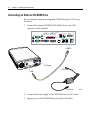
Installing a Second Cash Drawer
The terminal supports a 2‐drawer configuration with a Y‐cable (1416‐C372‐0006). 1. Place the cash drawer in the desired location, within cableʹs length of the printer. 2. Connect the Y‐cable to the transaction printer cash drawer connector. 2-18
Chapter 2: Hardware Installation
Calibrating the Touch Screen
Be sure to observe for the following Touch Screen calibration guidelines: •
Calibrate the touch screen as part of the installation process. •
Recalibrate the touch screen when the system is installed at its final location. •
Recalibrate whenever the terminal is moved to a new location. •
Recalibrate the touch screen anytime the system has been disassembled for servicing. •
The Touch Screen can be calibrated using MicroTouch (Windows) or Microcal (DOS), or it can be calibrated from the BIOS. •
If the Touch Screen or the Retail Daughter Card is replaced, the 25‐point calibration procedure is necessary. •
If the calibration is consistently off, even after performing the 2‐point calibration, then do the 25‐point. This should always be done before resorting to touch screen glass replacement. Chapter 2: Hardware Installation
2-19
Calibration Using MicroTouch (Windows)
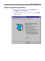
1. From the Windows Start button, select Settings→Control
Panel→MicroTouch Touchscreen. 2. From the MicroTouch Touchscreen Properties screen, select Calibrate to begin calibration. 2-20
Chapter 2: Hardware Installation
3. The following screen is displayed with two targets. Place your finger on the target that has a finger icon pointing towards it and hold it until the statement Touch Enable is displayed over the finger icon. Note: For best results, press the screen near the circle and then slide your finger onto the circle without raising your finger from the screen. 4. Using the same method as above, touch the circle near the upper‐
right corner of the screen. Chapter 2: Hardware Installation
2-21
5. The MicroTouch Calibration dialog box then appears. Do not touch the screen until this dialog box is no longer displayed. 6. From the Calibration Complete screen, select Done. 7. Select Close to exit the MicroTouch program. 8. From the Control Panel, select File→Close to exit the Control Panel. Calibration Using Microcal (DOS)
The calibration program looks at where your finger is when you lift it off the screen, not where you touch it. Therefore, calibrate the screen as follows: 1. Touch the screen near the calibration target. 2. Keep your finger on the screen and slide it to the center of the target. 3. Hold your finger firmly on the target for two seconds, then lift it off quickly. 4. Verify that the calibration was set accurately before making a service call. Perform the calibration again if necessary. 2-22
Chapter 2: Hardware Installation
If cursor is not stable, or false touches are suspected, run the Noise Check Utility from the Microcal program. Choose the recommended frequency (the one with the lowest noise level). This should also be done if the Touch Screen is still not calibrated after one attempt to recalibrate it. 1. Set the video resolution by going to the Tools menu, Video and selecting 800 x 600 256 colors. 2. Go to the Tools menu, select Noise Check. 3. Follow the instruction prompts. Choose the frequency with the lowest noise level. Application software can possibly generate a dialog box from the Touch Driver, with the message that the touch screen needs to be recalibrated. If the screen appears to be working normally, then this message can be ignored. There will be a check box labeled Do not
show this message again. Make sure this box is checked. Summary
If there is a Touch Screen calibration issue during or after installation, take the following actions in the order listed: 1. Recalibrate. 2. If recalibration is unsuccessful after two attempts, then run the Noise check to change the frequency. 3. If you are still unable to calibrate, change the touch screen glass. 4. The final step is to replace the Processor Board. If this corrects the problem, then the old glass is probably OK to reuse. Chapter 2: Hardware Installation
2-23
Out-of-Box Failures
The RSD‐Atlanta Customer Satisfaction Hotline will replace out‐of‐box failed hard disks with identical, preloaded drives. Once a system is successfully installed, all disk contents are the responsibility of the customer. The customer is responsible for restoring operating system software and/or customer‐specific data onto replacement disks sent to repair a failed or damaged disk in the field. NCR provides recovery tools for the operating system and platform software. Chapter 3: Setup
Entering Setup
1. Connect an alphanumeric PS/2 keyboard to the terminal. Note: If a USB keyboard is used then Legacy USB Support in the BIOS Setup must be enabled. 2. Apply power to the terminal. 3. When you see the American Megatrends logo displayed press [Del]. Keyboard Shortcuts
Function
Keystroke
Notes
Enter SETUP DEL 1 Load AMIBIOS “failsafe” CMOS SETUP values END Display extra AMIBIOS information at boot INS 8 Switch between AMIBIOS “Silent Boot” graphical logo and TAB standard text boot screen 2, 6 Boot from Network Device F12 1, 2 Enter SETUP after system error F1 1 Load CMOS SETUP defaults after system error F2 1 Initiate BIOS RECOVERY & clear CMOS CTRL‐HOME 7, 8 Initiate BIOS RECOVERY, clear CMOS & NVRAM CTRL‐PGUP 7, 8 Initiate BIOS RECOVERY, preserve CMOS & NVRAM CTRL‐PGDN 7 PopUp Boot Menu F8 or F11* 1, 2, 3 3-2
Chapter 3: Setup
Function
Keystroke
Notes
Enter SETUP (for serial console redirection) F4 1, 2, 3, 4 PopUp Boot Menu (for serial console redirection) F3 1, 2, 3, 4 Activate AMIKey Recovery Boot Services F9 1, 2, 5 Notes:
1. This keystroke can be configured to be a different value, based on the system manufacturer’s specification. The keystroke listed here is the “default” setting in AMIBIOS8. 2. This feature is not enabled in all AMIBIOS products. 3. The assigned keystroke & a short description of its function is typically displayed by the BIOS on system startup. 4. These keystrokes are only available when using the AMIBIOS “serial console redirection”, which allows access to the BIOS boot screen via a VT‐100/ANSI terminal connected to a serial port. 5. This feature is only available if AMIKey Recovery Boot Services are installed on the system drive and the BIOS is configured to use these services. 6. AMIBIOS will automatically switch from the “Silent Boot” logo to the standard BIOS text screen if an error occurs that requires user attention. Some error messages are displayed over the “Silent Boot” logo, depending on system configuration. 7. These BIOS functions are only available during the very early stages of system initialization, also known as “boot block code”. To initiate these functions, please hold down the keys immediately after powering on the system. 8. After AMIBIOS recognizes this keystroke, the BIOS will wait and display the following message: Press <F1> to Run SETUP, Press <F2> to load default values and continue. Chapter 3: Setup
3-3
How to Select Menu Options
The following keyboard controls are used to select the various menu options and to make changes to their values. •
Use the arrow keys to select (highlight) options and menu screens. •
Use the [Enter] key to select a submenu. •
Use the [+] and [-] keys to change field values. •
To view General Help at any time, press [F1]. •
To save the changes, move the cursor to the Exit Menu, select either Save Changes & Exits, and press [Enter]. 3-4
Chapter 3: Setup
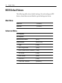
BIOS Default Values
The following tables show default settings. On such settings as IDE drives, where there are no defaults, typical settings are shown Main Menu
System Time
(variable) System Date
(variable) Advanced Menu
CPU Configuration
IDE Configuration
OnBoard PCI IDE Controller
[Both] Primary IDE Master
[Hard Disk] Type [Auto] LBA/Large Mode [Auto] Block (Multi‐Sector Transfer) [Auto] PIO Mode [Auto] DMA Mode [Auto] S.M.A.R.T. [Auto] 32Bit Data Transfer [Disabled] Chapter 3: Setup
Primary IDE Slave
[ATAPI CDROM] Type [Auto] PIO Mode [Auto] DMA Mode [Auto] Secondary IDE Master
[Not Detected] Secondary IDE Slave
[Not Detected] Hard Disk Write Protect
[Disabled] IDE Detect Time Out (Sec)
[35] ATA (PI) 80Pin Cable Detection
[Device] SuperIO Configuration
OnBoard Floppy Controller [Enabled] Serial Port A Address [3F8/IRQ4] Serial Port B Address [2F8/IRQ3] Serial Port 2 Mode [Normal] Serial Port C Address [3E8/IRQ10] Serial Port D Address [2E8/IRQ11] Parallel Port Address [378] Parallel Port Mode [ECP] ECP Mode DMA Channel [DMA3] Parallel Port IRQ [IRQ7] 3-5
3-6
Chapter 3: Setup
Hardware Health Configuration
[Enabled] H/W Health Function ACPI Configuration
Advanced ACPI Configuration
ACPI 2.0 Support [No] BIOSÆAML ACPI table [Enabled] Headless mode [Disabled] DMI Event Logging
Remote Access Configuration
[Disabled] Remote Access USB Configuration
Legacy USB Support [Enabled] USB 2.0 Controller Mode [HiSpeed] Multiple Option ROM Configuration
On‐board Intel LAN [Enabled] On‐board Intel PXE [Enabled] Parallel CD‐ROM Boot [Disabled] User ROM 3 [Disabled] User ROM 4 [Disabled] User ROM 5 [Disabled] User ROM 6 [Disabled] User ROM 7 [Disabled] Chapter 3: Setup
PCI/PnP Menu
Plug & Play O/S
[No] PCI Latency Timer
[64] Allocate IRQ to PCI VGA
[Yes] Palette Snooping
[Disabled] PCI IDE BusMaster
[Disabled] OffBoard PCI IDE Card
[Auto] DMA Channel 0
[Available] DMA Channel 1
[Available] DMA Channel 3
[Available] DMA Channel 5
[Available] DMA Channel 6
[Available] DMA Channel 7
[Available] Reserved Memory Size
[Disabled] 3-7
3-8
Chapter 3: Setup
Boot Menu
Boot Settings Configuration
Quick Boot [Disabled] Quiet Boot [Enabled] Boot Type [Cold Boot] AddOn ROM Display Mode [Force BIOS] Bootup Num‐Lock [On] PS/2 Mouse Support [Enabled] Typematic Rate [Fast] System Keyboard [Present] Parity Check [Disabled] Boot To OS/2 [No] Wait For ‘F1’ If Error [Enabled] Hit ‘DEL’ Message Display [Enabled] Interrupt 19 Capture [Disabled] Continuous POST [Disabled] After Power Failure [Last State] Boot Device Priority
1st Boot Device [IBA FE Slot 0441 v] 2nd Boot Device [1st Floppy Drive] 3rd Boot Device [IPS‐SR244W] 4th Boot Device [PM‐ST320410A] Chapter 3: Setup
Hard Disk Drives
1st Drive [PM‐ST320410A] 2nd Drive [SM‐ST320012A] Removable Drives
[1st Floppy Drive] 1st Drive ATAPI CDROM Drives
[PS‐SR244W] 1st Drive Initiate Pre-boot Services
[Hot Key] 3-9
3-10
Chapter 3: Setup
Security Menu
Supervisor Password:
:Not Installed User Password:
:Not Installed Change Supervisor Password
[Enter] Change User Password
[Enter] Clear User Password
[Enter] Boot Sector Virus Protection
[Disabled] Chipset Menu
Intel Montara-GML NorthBridge Configuration Primary Video Device [Auto] Graphics Mode Select [Enabled, 8MB1] IGD – Device 2,Function 1: [Enabled] Boot Type [CRT+LFP] Flat Panel Type: [800x600 LVDS] TV Standard: [Automatic] NTSC Minor Standards: [NTSC M] PAL Minor Standards: [PAL B] SECAM Minor Standards: [SECAM L] Flat Panel Scaling: [Auto] Intel ICH4 SouthBridge Configuration
ICH4 Dev31 Func1, IDE [Enabled] ICH4 Dev31 Func3, SMBUS [Enabled] ICH4 Dev31 Func5, AC’97 [Enabled] Chapter 3: Setup
ICH4 Dev29 Func8, USB#1 [Enabled] ICH4 Dev29 Func1, USB#2 [Enabled] ICH4 Dev29 Func2, USB#3 [Enabled] ICH4 Dev29 Func7, EHCI [Enabled] MIDI Decode [Disabled] Adlib Range 388h‐38Bh [Enabled] LPC 4Eh‐4Fh Decode [Enabled] LPC 2Eh‐2Fh Decode [Enabled] Onboard LAN [Enabled] IDAPIC [Disabled] Extended IDAPIC [Disabled] CPU B.I.S.T. [Disabled] ICH4 DMA Collection [Disabled] DMA‐0 Type [LPC DMA] DMA‐1 Type [LPC DMA] DMA‐2 Type [LPC DMA] DMA‐3 Type [LPC DMA] DMA‐4 Type [LPC DMA] DMA‐5 Type [LPC DMA] DMA‐6 Type [LPC DMA] DMA‐7 Type [LPC DMA] 3-11
3-12
Chapter 3: Setup
Chapter 4:
Operating System Recovery
Introduction
This chapter discusses procedures how to recover the Operating System using the integrated or an external USB CD‐ROM drive. Note: It is also possible to perform a BIOS update using a network connection. Refer to the NCR FitClient Software Userʹs Guide (B005‐0000‐1235) for information about that procedure. Prerequisites
The following are required in order to perform an OS recovery from a CD. •
Bootable CD‐ROM drive (internal or external) •
Keyboard 4-2
Chapter 4: Operating System Recovery
Connecting an External CD-ROM Drive
If your terminal contains an integrated CD‐ROM, skip to OS Recovery Procedures. 1. Connect the external CD‐ROM (2336‐K208) drive to the USB connector on the terminal. 24V USB
Cash Drawer
RS232/4
Line In
Mouse
Line Out
Kybd
RS232/2
Parallel
Mic
USB
USB
RS232/1
CRT
DVI
LAN
12V USB 12V USB
USB 2.0
DC Power
DC Power
USB
AC Power
21108
2. Connect the Power Supply to the CD‐ROM and to an AC outlet. 3. Apply power to the CD‐ROM drive (switch on the back). Chapter 4: Operating System Recovery
4-3
OS Recovery Procedures
1. Apply power to the terminal. 2. Press [DEL] during boot to enter Setup. 3. At the Setup Utility menu, select Advanced BIOS Features. 4. Set the First Boot Device to USB-CDROM. 5. The CDROM selection is used when you want to boot from an internal CD‐ROM drive. 6. Press [Esc] to return to the Setup Utility menu. 7. Select Save and Exit Setup. 8. As the system reboots, insert the NCR Partition Image Application CD (D370‐0605‐0100). You should see a message during boot, indicating that the CD‐ROM has been recognized. 9. At the menu, enter 1 to select the image restore function. ###############################
NCR Boot CD for Partimage
###############################
Select an option
1 – Restore an Image
2 – Exit to a shell
10. At the prompt, insert the CD which contains the operating system image. Press [Enter]. Windows 2000
D370‐0586‐0100 Windows NT
D370‐0587‐0100 Windows XPe
D370‐0588‐0100 11. At the prompt, press 1 (Yes) to Continue. 4-4
Chapter 4: Operating System Recovery
12. Press [Enter] to mount the CDROM, or [*] to cancel. +------+ Automatic mount +------+
|
|
| Please press “ok” to mount
|
| [/dev/cdrom] on [mnt/cdrom]
|
|
|
|
|
|
+----+
|
|
| Ok |
|
|
+----+
|
|
|
+-------------------------------+
Some Operating Systems occupy more than one CD. The restore program behaves differently between CDs, depending on which OS you are restoring: Win2000: The program will pause when it is time to insert the next CD, displaying the Automatic Mount message. Insert the next CD and press [Enter] to continue. WinNT: The program will pause when it is time to insert the next CD, without displaying any message. Press [Ctrl-Q] to continue. Insert the next CD and press [Enter] to continue. 13. Remove the CD from the drive. Chapter 4: Operating System Recovery
4-5
Completing the OS Installation
Windows 2000
The system automatically reboots when the image recovery is complete and starts the software installation. This installation also installs most of the additional software and drivers included in the disk image. Complete the installation as follows. 1. Accept the license agreement. 2. Enter the User Name and Organization. 3. Enter the Computer Name for the client. 4. Enter the Administrator’s Account Password (optional) 5. Login when prompted after the reboot. 6. Run the touch calibration (if using a touch screen). Windows NT 4.0
The system automatically reboots when the image recovery is complete and starts the software installation. This installation also installs most of the additional software and drivers included in the disk image. Note: The mouse port is disabled. You must use the keyboard to complete the installation. The mouse can be enabled later. Complete the installation as follows. 1. Accept the license agreement. 2. Enter the User Name and Organization. 3. Enter the Computer Name for the client. 4. Enter the Administrator’s Account Password (optional) 5. Login when prompted. 6. Run the touch calibration (if using a touch screen). Windows XPe
The system automatically reboots when the image recovery is complete and opens at the Welcome screen. 4-6
Chapter 4: Operating System Recovery
Gold Disk Contents
This section describes the contents of each of the Gold Disk Images, including all the additions and changes that were made on top of the generic operating system. For each operating system, NCR strongly recommends that the drivers placed in the c:\install directory be left there for the purposes of servicing and maintaining the system. If you are using the information in this section to build your own operating system image and not using NCRʹs provided OS Recovery image as a base image, then we recommend that all installed drivers be placed in a similar c:\install directory for support. Microsoft Operating System License Agreements
When purchasing a workstation or kiosk preloaded with a Microsoft operating system, the application provider must follow certain license agreement guidelines. Listed below are some of the major points of Microsoft’s “Embedded Software” agreement, which currently covers DOS, Win 3.11, Windows 95, Windows 98, Windows NT, Windows 2000, and Windows XPe. •
The end user application should not permit the user (typically a cashier) to exit the application so that they may be able to browse the operating system desktop, explorer, or other Microsoft operating system user interface elements. This does not apply to servicing, upgrading, or diagnosing problems for the workstation by services or field engineers. This restriction is meant to ensure that the end user is only permitted to navigate within the confines of the end user’s application under normal operating conditions. •
The NCR OS Recovery image can only be used to recover or update systems with licenses procured from NCR. Chapter 4: Operating System Recovery
4-7
Operating System Restrictions
Standby and Hibernate Mode Restriction
When using a 7402 terminal without a keyboard or mouse, the Windows 2000, Windows XP PRO, and Windows XP Embedded OS Standby Mode should be avoided. This mode places the hardware in a low power state that requires an interrupt to restart the processor. The Windows 2000 and Windows XP Embedded Gold Disk Images disable Standby Mode on the 7402 terminal. This mode should not be used without a keyboard or mouse. Note: Hibernate Mode is not supported. NCR 7402 Win2000OS Recovery Software
(LPIN: D370-0586-0100)
The NCR 7402 Windows 2000 Operating System Recovery Software provides the means of restoring the operating system to the terminal hard disk to the preinstalled state as shipped from the factory. Installed Software:
•
Microsoft Windows 2000 Professional w/ SP3 •
Security Rollup Package (SRP) 1 •
Microsoft Internet Explorer 6.0 with SP1 (6.0.2800.1106) •
Intel 85x Video driver (6.14.10.3606) •
Intel Control Panel •
RealTek Audio driver (5.10.0.4050) •
Intel Ethernet LAN driver (7.0.26.0) •
Intel ProSet diagnostic control panel application for LAN •
Windows Installer 2.0 •
Intel Application Accelerator installed (2.11.15.) •
Intel Chipset Software Installation Utility installed (5.0.1.1015) 4-8
Chapter 4: Operating System Recovery
•
Microsoft SNMP service installed but not activated •
Edgeport EPIC I/O Networks USB drivers available (2.30) •
3M TouchWare driver available (5.64 SR 2) •
Hampshire USB Touch available (6.07) •
Promise Raid Card available Software Drivers
The following drivers are not installed automatically, but can be installed from their respective locations (Readme files exist in these locations, as well): •
Edgeport USB •
Hampshire USB Touch C:\Install|Drivers\Hampshire USB
Touch •
Promise Raid Card C:\Install\Drivers\Edgeport USB C:\Install\Drivers\Promise Raid
Card Special Settings
Furthermore, the following settings/revisions are configured: •
Sysprep.inf answer file and sysprep.bat batch file created to: Accept EULA, Preinstall the Product ID Number (PID) •
Gold Drive Identification in Registry •
Terminal Check utility to validate that the OS Recovery is only being installed on NCR workstations •
Dynamic resolution configuration utility •
Dynamic RS232 touch detection utility Note: This product should only be used on NCR 7402 terminals with a Microsoft Windows 2000 license. Chapter 4: Operating System Recovery
4-9
Recommendation
For each operating system, NCR strongly recommends that any drivers placed in the C:\Install directory be left intact for the purposes of servicing and maintaining the system. If you are using this information in order to build your own operating system image and not using NCR’s provided OS Recovery image as a base image, we recommend that all drivers that are installed be placed in a similar C:\Install directory for support. 4-10
Chapter 4: Operating System Recovery
NCR RealPOS 7402 WinNT OS Recovery Software
(LPIN: D370-0587-0100)
The NCR 7402 Windows NT 4.0 Operating System Recovery Software provides the means of restoring the operating system to the terminal hard disk to the preinstalled state as shipped from the factory. Installed Software:
•
Microsoft Windows NT Workstation 4.0 w/ SP6a •
Microsoft Internet Explorer 6.0 SP1 (6.0.2800.1106 SP1) •
Intel Extreme Graphics Driver 2 13.2 Video (4.03.1381.3606) •
RealTek ACʹ97 Audio (ALC201A) (A3.35) •
Intel 82562 LAN driver(4.0.100.1124) •
Windows Installer (2.0) •
Backpack CD‐Rom available (2.04) •
3M TouchWare (5.64 SR2) •
Edgeport USB available (2.20) •
C&T Video available Software Drivers
The following drivers are not installed automatically, but can be installed from their respective locations (Readme files exist in these locations, as well): •
Backpack CD‐ROM C:\Install\Drivers\CDRom •
Edgeport USB C:\Install\Drivers\USB •
C&T Video C:\Install|Drivers\Video •
Promise Card C:\Install\Drivers\Promiseraid •
SIIG Card C:\Install\Drivers\SIIG Special Settings
Furthermore, the following settings/revisions are configured: Chapter 4: Operating System Recovery
•
Preinstalled NT to include the Product ID Number (PID) •
Placed the Gold Drive Part Number, Date Created, LPIN, and Release in Registry under: 4-11
HKey-Local_Machine\Software\NCR\Gold Drive
•
Ran Sysprep (so that the mini installation will run on initial boot) with the following parameters: ‐ Automatically include PID •
Host.cmd set in RunOnce to update the registry •
Established a 2gb FAT16 primary system partition •
Established a secondary NTFS partition that fills the remainder of the drive •
Included necessary OS cab files in C:\Install •
Made SP6a folder available in C:\Install (installed) •
Made I386 folder available in C:\Install •
Installed MS SNMP, set to Manual •
Replaced the standard EULA with the NCR‐specific EULA. •
TerminalCheck.exe in Run registry to determine correct hardware platform (otherwise it will shut down) •
Hide MS splash screen by adding /noguiboot parameter to boot.ini •
SerMouse device disabled •
Added /noserialmice to boot.ini •
Set resolution to 800x600 •
Set colors to 65536 •
Disabled MousClass service •
Updated C:\Install\drivers\touch folder to Microtouch 5.64 SR1 •
20.Manually added Com5 Note: This product should only be used on NCR 7402 terminals with a Microsoft Windows NT 4.0 license. 4-12
Chapter 4: Operating System Recovery
Recommendation
For each operating system, NCR strongly recommends that any drivers placed in the C:\Install directory be left in tack for the purposes of servicing and maintaining the system. If you are using this information in order to build your own operating system image and not using NCRʹs provided OS Recovery image as a base image, we recommend that all drivers that are installed be placed in a similar C:\Install directory for support. Chapter 4: Operating System Recovery
4-13
NCR 7402 Windows XPe Operating System Recovery Software
(LPIN: D370-0588-0100)
The NCR 7402 Windows XPe Operating System Recovery Software provides the means of restoring the operating system to the terminal hard disk to the preinstalled state as shipped from the factory. Installed Software:
•
Microsoft Windows XPe w/ SP1 •
Intel Extreme Video (6.14.10.3606) •
Intel Pro/100 LAN (7.0.26.0) •
Intel Chip Set Utility (5.01.1015) •
RealTek Audio Driver (5.10.0.4050) •
MicroTouch drivers available (5.64 SR1) •
Hampshire TSHARC USB Touch Drivers available (6.07) •
Edgeport USB drivers (2.30) •
Globetek drivers available (2.55.4.0) •
Promise FastTrak Raid Driver available (2.00.0.34) Software Drivers
The following drivers are not installed automatically, but can be installed from their respective locations (Readme files exist in these locations, as well): •
3M TouchWare C:\Install\Drivers\Touch •
Globetek C:\Install\Drivers\Camera •
Hampshire USB Touch C:\Install|Drivers\Hampshire_
USB_Touch •
Promise Raid Card C:\Install\Drivers\Promise Raid 4-14
Chapter 4: Operating System Recovery
Special Settings
Furthermore, the following settings/revisions are configured: •
Preinstalled XPe to include the Product ID Number (PID) •
Placed the Gold Drive Part Number, Date Created, LPIN, and Release in Registry under: HKey-Local_Machine\Software\NCR\Gold Drive •
Established a NTFS primary system partition that fills the entire drive •
Installed RealTek Audio Driver •
Installed Intel Chipset Utility •
Installed Intel LAN Driver •
Set virtual memory to 384 •
Added NCR‐specific EULA Note: This product should only be used on NCR RealPOS 80/80c terminals with a Microsoft Windows XPe license. Recommendation
For each operating system, NCR strongly recommends that any drivers placed in the C:\Install directory be left intact for the purposes of servicing and maintaining the system. If you are using this information in order to build your own operating system image and not using NCR’s provided OS Recovery image as a base image, we recommend that all drivers that are installed be placed in a similar C:\Install directory for support. Chapter 5:
BIOS Updating Procedures
Introduction
This chapter discusses procedures how to update the terminal BIOS by using the parallel CD‐ROM drive. The software is distributed on bootable CD‐ROM media. The drivers that are necessary to run the CD‐ROM are temporarily installed during boot. It is also possible to perform a BIOS update using a network connection. Refer to the NCR FitClient Software Userʹs Guide (B005‐0000‐1235) for information about that procedure. Crisis Recovery
In the event the BIOS becomes corrupt, such as the result of a power failure during the BIOS Update procedure, you can use the method discussed later in this chapter in the BIOS Crisis Recovery section to recover the BIOS. Prerequisites
The following are required on the 7402 in order to perform a BIOS update using a CD. •
Bootable CD‐ROM drive (2336‐K024) •
Keyboard NCR 7402 BIOS and BIOS Update Software (LPIN: A370‐0056‐0100) 5-2
Chapter 5: BIOS Updating Procedures
Connecting an External CD-ROM Drive
If your terminal contains an integrated CD‐ROM, skip to Updating Procedures. 4. Connect the external CD‐ROM (2336‐K208) drive to the USB connector on the terminal. 24V USB
Cash Drawer
RS232/4
Line In
Mouse
Line Out
Kybd
RS232/2
Parallel
Mic
USB
USB
RS232/1
CRT
DVI
LAN
12V USB 12V USB
USB 2.0
DC Power
DC Power
USB
AC Power
5. Connect the Power Supply to the CD‐ROM and to an AC outlet. 21108
Chapter 5: BIOS Updating Procedures
5-3
Updating Procedures
1. Apply power to the terminal. 2. Press [DEL] during boot to enter Setup. 3. In the Advanced menu, select I/O Device Configuration. 4. Verify that the LPT 1 Mode is set to ECP. 5. Go back to the Advanced menu, select Multiple ROM Menu. 6. Set the Parallel CD-ROM Boot to Enabled. 7. In the Exit menu, select Save Changes and reboot. 8. Insert the media containing the BIOS update onto the spindle. NCR 7402 BIOS and BIOS Update Software (LPIN: A370‐0056‐0100) 9. Follow the screen prompts on the client to update the BIOS. You can select two methods to run the update program. •
Automatic BIOS Update – update process runs unattended Note: You will see a prompt for terminal model and serial number information if the program detects invalid information in the current BIOS, or if you are replacing the processor board, in which case there is not model/serial number information in the BIOS. Important: Model/Serial Number is mandatory. •
Interactive BIOS Update – permits you to input/replace the model/serial number information that is stored in the BIOS. Note: Model/Serial number data that is currently stored in the BIOS is displayed during power up. 10. You should see a green window, indicating a successful update. 11. Remove the CD. 12. Press any key to reboot. 5-4
Chapter 5: BIOS Updating Procedures
13. When the system reboots, press [F2] (7402‐3xxx) or [DEL] (7402‐
4xxx) during boot to enter Setup. 14. In the Exit menu, select Load Setup Defaults. 15. Go to the Advanced menu and set Reset Configuration Data to [Yes]. 16. Exit Setup and Save Changes. Chapter 5: BIOS Updating Procedures
5-5
BIOS Crisis Recovery
The procedures below provide a way to restore the BIOS resulting from a non‐recoverable condition. Note: Use this BIOS crisis recovery procedure only for a NON‐RECOVERABLE BIOS failure. A non‐recoverable BIOS state typically results from power loss during a flash BIOS update process. This is a rare occurrence and should not be confused with other hardware errors that cause a no video state. This procedure is not intended to be used for changing or upgrading an operational BIOS. Required Hardware
Part Number
Part Name
Use
PC with an RS‐232 port Download BIOS 497‐0408349 Cable, 9‐Pin Female to 9‐Pin Female RS232 PC to terminal connection 497‐0413418 Parallel Dongle Forces BIOS recovery Required Software
Acquire the following software from NCR. NCR 7458‐4xxx BIOS and BIOS Update Software (LPIN: A370‐0056‐0100) 5-6
Chapter 5: BIOS Updating Procedures
Recovery Procedures
1. Connect the Parallel Dongle to the parallel connector on the terminal. 2. Connect the two machines with an RS‐232 cable. Use COM1 on both machines. PC
RS-232 Cable
24V USB
Cash Drawer
RS232/4
Line In
Mouse
Line Out
Kybd
RS232/2
Parallel
Mic
USB
USB
RS232/1
CRT
DVI
LAN
12V USB 12V USB
RS-232 (COM1)
21095
3. Boot the PC in the DOS mode. (If you are using CD‐ROM media boot with CD‐ROM support drivers.) Note: The PC must be running in the DOS mode (not in a Windows DOS box) for the software to operate correctly. 4. Insert the BIOS update CD into the PC. 5. Apply power to the terminal. Chapter 5: BIOS Updating Procedures
5-7
6. On the PC, change directory to the CD‐ROM drive. E: [Enter]
7. Enter the update command: EMBflash [Enter]
8. Select the number for the 7402 terminal from the menu list: 1)
2)
3)
4)
5)
6)
7)
8)
9)
7454
7401
7452
7453
7455
7460
7451
7456
7458
9 [Enter]
A blue screen displays as the program runs, showing the program progress, followed by a green screen, indicating a successful load. PhoenixPhlash Status
Flash memory has been successfully programmed
PRESS ANY KEY TO EXIT
19502
The Class/Model/Serial # information is deleted using the Crisis Recovery procedure. Use the normal BIOS update procedures as discussed earlier in this chapter to restore the information. 5-8
Chapter 5: BIOS Updating Procedures
Cable/Connector Pin-Out Information
Parallel Dongle
25-Pin D-shell Receptacle
(Viewed from wiring side)
13
12
25
11
24
10
23
9
22
8
21
7
20
6
19
5
4
17
18
3
16
2
15
1
14
19513
RS-232 Cable
P1
5
9
1
6
P2
9-Pin
D-shell
Receptacle
1
1
2
2
3
4
3
5
5
6
6
7
7
9-Pin
D-shell
Receptacle
5
9
1
6
4
8
8
P1
P2
19512
Chapter 6: 2x20 Customer Display
Introduction
The 2x20 Customer Display consists of a Vacuum Florescent Display (VFD) with two rows of twenty 5x8 dot matrix characters, an RS‐232 serial interface, driver circuitry, DC to DC/AC converter, and a character generator. General Specifications
Item
Value
Number of characters 2 Rows x 20 Characters Character Configuration 5x8 Character Height 8.86 mm Character Width 3.90 mm Character Pitch 5.15 mm Line Pitch 9.64 mm Peak Wavelength of Illumination 505 mm Luminance 350 Cd/m2 (102 fL) (Minimum), 700 Cd/m2 (204 fL) (Typical) Serial Communication Interface
The display receives commands and data from the host using an RS‐232 serial interface, framed at 9600 baud, 8 data bits, no parity, and one stop bit. 6-2
Chapter 6: 2x20 Customer Display
Command Codes
User Defined Character Definition (08h, CODE, Byte1…Byte5)
This command defines a user defined character (UDC). The UDC character code is set by the CODE byte and must be 00H to 07H. All other values for CODE will this command. The five bytes following a valid CODE byte define the character. D1 through D40 represent the character dots. A (1) indicates the dot is on and (0) indicates the dot is off in the following format: D1 D2 D3 D4 D5 D6 D7 D8 D9 D10 D11 D12 D13 D14 D15 D16 D17 D18 D19 D20 D21 D22 D23 D24 D25 D26 D27 D28 D29 D30 D31 D32 D33 D34 D35 D36 D37 D38 D39 D40 5 x 8 Dot Matrix Character
BYTE#
Bit 7
Bit 6
Bit 5
Bit 4
Bit 3
Bit 2
Bit 1
Bit 0
1 D1 D2 D3 D4 D5 D6 D7 D8 2 D9 D10 D11 D12 D13 D14 D15 D16 3 D17 D18 D19 D20 D21 D22 D23 D24 4 D25 D26 D27 D28 D29 D30 D31 D32 5 D33 D34 D35 D36 D37 D38 D39 D40 Chapter 6: 2x20 Customer Display
6-3
Character Table Select (09h, TABLE CODE)
This command selects which character table to display. The TABLE CODE byte determines the character set as defined in the table below. If bits 0 to 3 are all zero then this command is ignored. When a new character table is selected all characters on the display will be updated to display the character of the new table. After a reset the character table is set to Table 1. Table Code
Character Table
01h Table 1 02h Table 2 03h Table 3 04h Table 4 Clear Display (12h)
This command sets all 40 characters to 20h (space) and moves the cursor to the first position of the top line. Luminance Control (11h, LUMINANCE)
This command selects the display luminance. The LUMINANCE byte sets the display luminance level as defined in the table below. This command is ignored if the LUMINANCE byte is 00h. LUMINANCE
Display Luminance
01h 25% 02h 50% 03h 75% 04h 100% 6-4
Chapter 6: 2x20 Customer Display
Cursor Position (10h, POSITION)
This command sets the cursor position. The POSITION byte moves the cursor position according to the table below. The next character byte writes to the new position and the cursor auto‐increments to the next position. This command is ignored if the POSITION byte value is greater than 27h. 1
2
3
4
5
6
7
8
9
10
11
12
13
14
15
16
17
18
19
20
1
00h 01h 02h 03h 04h 05h 06h 07h 08h 09h 0Ah 0Bh 0Ch 0Dh 0Eh 0Fh 10h 11h 12h 13h 2
14h 15h 16h 17h 18h 19h 1Ah 1Bh 1Ch 1Dh 1Eh 1Fh 20h 21h 22h 23h 24h 25h 26h 27h Reset (13h)
This command resets the module to the following conditions: •
100% luminance •
All 5x8 dot matrix characters set to 20h (space) •
Cursor position set to 00h •
Character table set to Table 1 •
All user defined characters cleared Character Tables and Codes
Data is written to the display one byte at a time. If the byte received is greater than 1Fh it is considered as 5x8 dot matrix character data. This character is written to the current cursor position and the cursor position is then incremented by one. When data is written to the last character position of the top line the cursor position moves to the first position of the bottom line. When data is written to the last character position of the bottom line the cursor position moves to the first position of the top line. Chapter 6: 2x20 Customer Display
6-5
CP437
6-6
Chapter 6: 2x20 Customer Display
CP858
Chapter 6: 2x20 Customer Display
6-7
CP866
6-8
Chapter 6: 2x20 Customer Display
CP932
Chapter 7: Cash Drawer Interface
Introduction
This document is intended to be a guide for writing software to use the 7402 cash drawer interface. It is intended to assist software engineers to design and code software to control the cash drawer port. This is not a specification on the cash drawer interface. The sample code included has not been compiled or tested but can be helpful in coding the cash drawer interface. The 7402 cash drawer interface has unique signals to: •
control the cash drawer solenoid(s) for up to 2 cash drawers. •
enable the arming of an external driving circuit. •
for reporting the status of the drawer, either open or close (input signal). Logic Description
long Initialize( );
Initialize () creates the mutex handles and opens the NCR port driver if the OS requires it. void Terminate();
Terminate() closes the handles to the mutexes and the NCR port driver if opened. long OpenPort();
OpenPort () initializes the port by calling QueryConf() and sets the solenoid control bits and the arming bit to inputs. 7-2
Chapter 7: Cash Drawer Interface
long OpenDrawer();
OpenDrawer (), sets the control bits to output, enables the arming circuitry using the arm bit, energizes the solenoid of the selected drawer, waits a constant time, then releases the cash drawer solenoid(s) bit(s) and disables the arming circuit. These output bits are then configured as inputs again. This method uses SetState() for controlling the drawer. See the section on Hardware/Firmware Interfaces for more detail. void ClosePort();
ClosePort() resets the port opened status flag to false. DWORD GetDrawerStatus();
GetDrawerStatus (), reads from the port that monitors the cash drawer status bit and masks unused bits to determine the drawer state. This method uses ReadIOPort () for monitoring the status bit. See the section on Hardware/Firmware Interfaces for more detail. BOOL SetState( DWORD dwState );
SetState (), uses the constant masks to create the data to write to the port that control the cash drawer solenoid(s) bit(s). This method uses WriteIOPort () for controlling the solenoid(s). See the section on Hardware/Firmware Interfaces for more detail. BOOL QueryConf();
In QueryConf(), we must initiate a configuration cycle with the PCI registers that control the cash drawer solenoid(s) and monitor the status bit. Interaction with GPIO_BASE (General Purpose I/O Base Address Register) takes place in order to determine the port address used for controlling the solenoid(s) and for monitoring the status bit. See the section on Hardware/Firmware Interfaces for more detail. Chapter 7: Cash Drawer Interface
7-3
BOOL WriteIOPort( DWORD databytes, WORD ioport );
WriteIOPort (), writes data to the port that control the cash drawer solenoid(s) bit(s). This method uses the port address obtained in QueryConf() for controlling the solenoid(s). See the section on Hardware/Firmware Interfaces for more detail. BOOL ReadIOPort( DWORD *databytes, WORD ioport );
ReadIOPort (), reads from the port that monitors the cash drawer status bit. This method uses the port address obtained in QueryConf() for monitoring the status bit. See the section on Hardware/Firmware Interfaces for more detail. 7-4
Chapter 7: Cash Drawer Interface
Component Architecture
The developer should provide a description, either textually or diagrammatically (i.e., block diagram), of how the components of the module subsystem interact in this sub‐section. The member function Initialize() is subsequently called to open the NCR Windows NT port driver (if applicable) and perform other initialization tasks. Then, the device’s OpenPort() member function is called to make the device available, at which time QueryConf() is called. Once the device has been configured, the member functions OpenDrawer(), GetDrawerStatus() and SetState() can be called to interact with the cashdrawer. These methods themselves invoke the member functions WriteIOPort() and ReadIOPort() to actually send and receive data to the cashdrawer via the port addresses obtained in QueryConf(). Code Changes
Following is an enumeration of the code changes needed to support the 7402: The interface of the new device supports two separate fields for GPIO select port address (read/write) and solenoid and status bit port address (read/write). The chip GPIO bits must be selected for use as GPIO and as either input or output. It is desired that the driving circuit be disabled at power on and when not actively driving the solenoid. Two output control implementations will be used: 1. Use the m_nIOPort_Select address register to set the solenoid bit to an output function before driving the bit high using m_nIOPort, set the solenoid bit low after the charging time and then setting the bit function to input using m_nIOPort_Select. Chapter 7: Cash Drawer Interface
7-5
2. Use the arming bit at address m_nIOPort to enable an external driving circuit, set the solenoid bit high, set the solenoid low after the charge time and finally disable the arming bit. QueryConf(): QueryConf() uses the PCI configuration cycle protocol at Bus 0, Device 31 and Function 0 and offset 0x58 to obtain the contents of GPIOBase register. When GPIOBase is referenced in the following paragraphs it is referring to the contents of register GPIOBase [15:6]. The primary differences are: a. One port address needs to be configured for reading the status bit and reading/writing to control the cash drawer solenoids, and if necessary the ARM bit using register GPIO Level for Input or Output 2 Register (GP_LVL2) offset GPIOBase + 0x38. b. GPIO must be selected for use as GPIO through register GPIO Use Select 2 Register (GPIO_USE_SEL2) offset GPIOBase + 0x30. c. GPIO bits used by the cash drawer must be selected as either input or output through GPIO Input/Output Select 2 Register(GP_IO_SEL2) GPIOBase + offset 0x34. d. An ARM bit may need to be setup as output and controlled with the solenoid and status port address. This bit enables the driving circuit for the solenoid outputs. 7-6
Chapter 7: Cash Drawer Interface
Hardware/Firmware Interfaces
In some previously supported models, no preliminary interaction with the hardware was required to determine the port address(s) used for communication with the cash drawer; these data were instead obtained from the registry. For the 7402, the port address is set dynamically by the BIOS and hence the hardware must be queried to obtain this information. This dictates the need for the generation of a configuration cycle as described previously. Configuration mechanism one utilizes two 32bit I/O ports located at addresses 0x0CF8 and 0x0CFC. These two ports are: •
32‐bit configuration address port ‐ occupying I/O addresses 0x0CF8 through 0x0CFB. •
32‐bit configuration data port ‐ occupying I/O addresses 0x0CFC through 0x0CFF. Accessing a PCI function’s configuration port is a two step process: •
Write the target bus number, physical device number, function number and doubleword number to the configuration address port •
Perform an I/O read from or a write to the configuration data port. The ICH4 Configuration Address Register should be defined as follows: •
Configuration Space Mapping enabled •
Bus number 0 •
Device number 31 •
Function number 0 •
GPIO base register offset address 0x58 Chapter 7: Cash Drawer Interface
7-7
Within the ICH4, the General Purpose I/O ports are addressed using an offset read from the GPIO Base Address Register, [GPIOBASE] (offset 0x58). The base address included in Bits [15:6] is assigned by the BIOS. The GPIO Control Register [GPIO_CNTL] (offset 0x5C) has a R/W bit [4] that enables(1)/disables(0) the decode of the I/O range pointed to by the GPIO Base register and enables/disables the GPIO function. The GPIO Control Register is set by the BIOS to enable GPIO. Intel® 82801DB ICH4 Datasheet
GPIO_USE_SEL2—GPIO Use Select 2 Register
Offset Address: GPIOBASE +30h Attribute: R/W
Default Value: 00000FFFh Size: 32-bit
Lockable: No Power Well: Core
Bit Description
31:0
GPIO_USE_SEL2[43:32] — R/W. Each bit in this register enables the corresponding GPIO (if it exists) to be used as a GPIO, rather than for the native function. 0 = Signal used as native function. 1 = Signal used as a GPIO. For 7402, cash drawer bits GPIO_USE_SEL2 [35:32] will be set =1 for use as a GPIO, write value = read value ANDed with 0xF. After a full reset (RSMRST#) all multiplexed signals in the resume and core wells are configured as their native function rather than as a GPIO. After just a PCIRST#, the GPIO in the core well are configured as their native function. LPC Interface Bridge Registers (D31:F0)
GP_IO_SEL2—GPIO Input/Output Select 2 Register
Offset Address: GPIOBASE +34h Attribute: R/W
Default Value: 00000000h Size: 32-bit
Lockable: No Power Well: Core
7-8
Chapter 7: Cash Drawer Interface
GP_LVL2—GPIO Level for Input or Output 2 Register
Offset Address: GPIOBASE +38h Attribute: R/W
Default Value: 00000FFFh Size: 32-bit
Lockable: No Power Well: See below
Bit Description
31:12 Always 0. No corresponding GPIO.
11:0
GP_IO_SEL2[43:32] — R/W. When set to a 1, the corresponding GPIO signal (if enabled in the GPIO_USE_SEL2 register) is programmed as an input. When set to 0, the GPIO signal is programmed as an output. Bit Description
31:12 Reserved. Read-only 0
11:0
GP_LVL2[43:32] — R/W. If GPIO[n] is programmed to be an output (via the corresponding bit in the GP_IO_SEL2 register), then the corresponding GP_LVL2[n] bit can be updated by software to drive a high or low value on the output pin. 1 = high, 0 = low. If GPIO[n] is programmed as an input, then the corresponding GP_LVL2 bit reflects the state of the input signal (1 = high, 0 = low). Writes will have no effect. Since these bits correspond to GPIO that are in the core well, these bits will be reset by PCIRST#. Three GPO bits and one GPI bit of South Bridge ICH4 are used to control the cash drawer(s). They are defined below: GPIO 32 CD_SW_AB
Input 1, high Drawer(s) closed. Input 0, low Drawer(s) open. GPIO 33 CD_SOL_A
Output 0, low turn off solenoid A. Output 1, high Activates Solenoid A. GPIO 34 CD_SOL_B
Output 0, low turn off solenoid B. Output 1, high Activates Solenoid B. Chapter 7: Cash Drawer Interface
7-9
GPIO 35 CD_ARM
Output 0, low Drawer(s) solenoid signals enabled. Output 1, high disabled. There is only one cash drawer status signal CD_SW_AB. It is the status of either cash drawer or both cash drawers. 7-10
Chapter 7: Cash Drawer Interface
Dependencies/Assumptions/Constraints
Hardware Dependencies
Constraint: For systems in which two cashdrawers are in use on the Darlington, the drawers must share a status bit using a ‘Y’ cable. Software Dependencies
NCR Windows NT Port Driver (NCRKMPDR.sys). Sample Code
CPP Source File: DarlingtonCDSample.cpp
long Initialize( )
{
// Init -- I/O Port -- Standard Configuration Register Address for PCI
Devices
m_nIOConf = 0x0CF8;
// Read -- I/O Port -- If these defaults are left unchanged, errors will be
reported
m_nIOPort = 0; // R/W port for solenoid bits and status
m_nIOPort_select = 0; //R/W port for selecting GPIO Input/Output config
m_nDrawerNumber = 1; //Default
m_bPortDrvr = FALSE;
// determine if OS is WIN95 or WINNT
if (GetVersion() < 0x80000000)
{
m_nOSVersion = OS_WINDOWS_NT;
// Lock Mutex when accessing shared memory TAR 95236
WaitForSingleObject( g_hSharedMemoryMutex, INFINITE );
if ( g_hPortDrvr == NULL )
Chapter 7: Cash Drawer Interface
7-11
{
// -rtf- Create a security attribute allowing global access
GetGlobalSA( _T("CreateFile"), _T("NCRKPDev"), &m_Attributes, &m_SD
);
g_hPortDrvr = CreateFile(
"\\\\.\\NCRKPDev",
// Open the Device "file"
GENERIC_WRITE | GENERIC_READ,
FILE_SHARE_READ | FILE_SHARE_WRITE,
(LPSECURITY_ATTRIBUTES) &m_Attributes, // no security
OPEN_EXISTING,
0,
// flags
NULL);
if (g_hPortDrvr == INVALID_HANDLE_VALUE)
{
DWORD hr = GetLastError();
// Was the device opened?
m_bPortDrvr = FALSE;
InitError = TRUE;
}
else
{
m_bPortDrvr = TRUE;
}
}
// end if (g_hPortDrvr==0)
ReleaseMutex( g_hSharedMemoryMutex );
} // WINNT OS
else
{
m_nOSVersion = OS_WINDOWS_95;
}
} // end if (!InitError)
// if the (OS is WINNT AND the port driver was opened )
if ( !InitError )
{
// Create a security attribute allowing global access
GetGlobalSA( _T("mutex"), sData, &m_Attributes, &m_SD );
7-12
Chapter 7: Cash Drawer Interface
// Lock Mutex when accessing shared memory
WaitForSingleObject( g_hSharedMemoryMutex, INFINITE );
g_hHWPortMutex = CreateMutex( &m_Attributes, FALSE, (LPCTSTR) sData );
if ( g_hHWPortMutex != NULL )
{
m_pDC->DCPrintf(
DCM_APIHIGH,
_T(" ..create m_hPowerMutex") );
// Create a security attribute allowing global access
GetGlobalSA( _T("mutex"), _T("NCRPowerSharingMutex"), &m_Attributes,
&m_SD );
// create named mutex that prevents the cash drawer from firing
// when the printer is printing
// "NCRPowerSharingMutex"
m_hPowerMutex = CreateMutex( &m_Attributes, FALSE,
_T("NCRPowerSharingMutex") );
}
// HWPortMutex created
}
ReleaseMutex( g_hSharedMemoryMutex );
}
// OS is WIN95 or WINNT and NCRKPDev driver present
return RetStatus;
}
// TAR 95236
Chapter 7: Cash Drawer Interface
7-13
///////////////////////////////////////////////////////////////
void Terminate()
{
if ( m_bInitialized )
{
// Lock Mutex when accessing shared memory
WaitForSingleObject( g_hSharedMemoryMutex, INFINITE );
CloseHandle( m_hPowerMutex );
CloseHandle( g_hHWPortMutex );
// TAR 95236
// if the NT port driver was opened...
if (m_bPortDrvr )
{
// close the file handle
m_bPortDrvr = FALSE;
g_nPortDrvr=0;
// Dec to zero using and close handle
CloseHandle(g_hPortDrvr);
g_hPortDrvr = NULL;
}
m_bInitialized = FALSE;
ReleaseMutex( g_hSharedMemoryMutex );
}
}
/////////////////////////////////////////////////////////
long OpenPort()
{
CString sData;
long RetStatus;
CString Result;
static TCHAR szIOPort[] = _T("Port");
// Get the IO H/W Configuration to set IOPORT addresses
// If other of same type exists then use same IOPort addresses
QueryConf(); // Sets IOPORT addresses based on H/W configuration
// initialize state
DWORD sBytes=0;
DWORD bMask = ~(CD7402DRWR1SOLENOID | CD7402DRWR2SOLENOID); // Set
Solenoid bits LOW
bMask = bMask | CD7402ARM_OFF; // set solenoid bits low and arm bit high
// **program solenoid bits as inputs to start
if ( !ReadIOPort(&sBytes, m_nIOPort_select) )
{
// Error logged in ReadIOPort
7-14
Chapter 7: Cash Drawer Interface
RetStatus = CDD_E_IOFAILURE;
Result = _T("I/O read operation failed");
}
else if ( !WriteIOPort( sBytes | CD7402SELECT_GPI,
m_nIOPort_select)) // Darlington 1 = select input
{
// Error logged in WriteIOPort
RetStatus = CDD_E_IOFAILURE;
Result = _T("I/O write operation failed");
}
//** set solenoid bits de-activated, even though they are supposed to be
inputs now
if ( !ReadIOPort(&sBytes, m_nIOPort) )
{
// Error logged in ReadIOPort
RetStatus = CDD_E_IOFAILURE;
Result = _T("I/O read operation failed");
}
// Darlington 0 = solenoid de-activated, 1 = ARM de-activated
else if ( !WriteIOPort( sBytes & bMask,
m_nIOPort))
{
// Error logged in WriteIOPort
RetStatus = CDD_E_IOFAILURE;
Result = _T("I/O write operation failed");
}
else
{
RetStatus = CDD_SUCCESS;
Result = _T("Success");
m_bIFOpened = TRUE;
//InterFace is OPENed
// initialize Position variable in aCDData array element
GetDrawerStatusLIO();
}
return RetStatus;
}
Chapter 7: Cash Drawer Interface
7-15
///////////////////////////////////////////////////////////////////////
void ClosePort()
{
if ( m_bIFOpened )
{
m_bIFOpened = FALSE;
}
}
//////////////////////////////////////////////////////////////////////////////
// CDevice7402::OpenDrawer [called from polling thread]
long OpenDrawer()
{
long RetStatus;
CString RetString;
WaitForSingleObject( g_hHWPortMutex, INFINITE );
// TAR 95236
if ( m_bIFOpened )
{
WaitForSingleObject( m_hPowerMutex, INFINITE );
// Set Device in RELEASE State
if ( SetState( STATE_RELEASE ) )
{
// Give time for Drawer to see the RELEASE state change, then
// check the drawer position.
Sleep( CD7402_OPEN_WAIT );
// Set Device in IDLE State
if ( SetState( STATE_IDLE ) )
{
if (( GetDrawerStatusLIO() == DRAWER_OPENED ) ||
( m_pCashDrawer->m_bCapStatus == FALSE))
// no drawer status
available return success
{
RetStatus = OPOS_SUCCESS;
}
else
{
RetStatus = OPOS_E_TIMEOUT;
}
}//SetState( STATE_IDLE )
else
{
RetStatus = OPOS_E_NOEXIST;
7-16
Chapter 7: Cash Drawer Interface
}
}//SetState( STATE_RELEASE )
else
{
RetStatus = OPOS_E_NOEXIST;
}
ReleaseMutex( m_hPowerMutex );
}
ReleaseMutex( g_hHWPortMutex );
return RetStatus;
}
//////////////////////////////////////////////////////////////////////////////
// CDevice7402::GetDrawerStatus [called from polling thread]
//
// Return Value:
DrawerStatus
//
DRAWER_OPENED
//
DRAWER_CLOSED
//
DWORD GetDrawerStatus()
{
int Result;
CString ResString;
DWORD bMask;
Result = DRAWER_INVALID;
ResString = _T("INVALID");
if ( m_bIFOpened && ( m_pCashDrawer->m_bCapStatus) ) // Opened and Drawer
status is available
{
switch( m_nDrawerNumber )
{
case 1:
bMask = CD7402DRWR1CLOSED;
break;
case 2:
bMask = CD7402DRWR2CLOSED;
break;
}
DWORD sBytes;
// if the status clear was successful, we will read a closed drawer
BOOL sResult = ReadIOPort(&sBytes, m_nIOPort);
Chapter 7: Cash Drawer Interface
7-17
if ( sResult )
{
if ( sBytes & bMask ) // bit = 1 means drawer CLOSED for DARLINGTON
{
ResString = _T("CLOSED");
Result = DRAWER_CLOSED;
}
else
{
ResString = _T("OPENED");
Result = DRAWER_OPENED;
}
}//sResult
}
return Result;
}
//////////////////////////////////////////////////////////////////////////////
// CDevice7402::SetState
BOOL SetState( DWORD dwState )
{
// Fire cashdrawer mechanism by setting drawer to the RELEASE State.
// Can't open both cash drawers at the same time. Must set H/W mutex
// in OpenDrawerLIO() around SetState(RELEASE) and SetState(IDLE) to
// insure this.
// To engage solenoid, we must set the solenoid bit HIGH and the ARM bit
// LOW. The ARM bit controls the external arming circuit to drive the
// solenoid.
CString sState;
DWORD bMask;
DWORD sBytes = 0;
DWORD oBytes = 0;
BOOL result = TRUE;
// Read select register
// Solenoid GPIO bits and ARM bit have been set to input when not using.
if ( ReadIOPort(&sBytes, m_nIOPort_select) )
{
// solenoid bits and ARM bit as outputs, Low enables output
sBytes = sBytes & CD7402SELECT_GPO;
result = WriteIOPort( sBytes, m_nIOPort_select );
}
else
// Error logged in ReadIOPort
7-18
Chapter 7: Cash Drawer Interface
result = FALSE;
if(result)
{
switch( m_nDrawerNumber )
{
case 1:
// set solenoid bit high, arm bit low
bMask = CD7402DRWR1SOLENOID;
break;
case 2:
bMask = CD7402DRWR2SOLENOID;
break;
}
// Read solenoid bit
if ( ReadIOPort(&oBytes, m_nIOPort) )
{
switch (dwState)
{
case ( STATE_RELEASE ):
// activate solenoid (open cash drawer)
// bit = 1 activates solenoid, = 0 de-activates
// Set the solenoid bit ON to energize, leave other bits alone
oBytes = oBytes | bMask;
// driving circuit arming bit,LOW for arming
oBytes = oBytes & CD7402ARM_ON;
result = WriteIOPort( oBytes, m_nIOPort );
sState = _T("STATE_RELEASE");
break;
case ( STATE_IDLE ):
// deactivate solenoid
oBytes = oBytes & (~bMask);
// Set the solenoid bit OFF to deenergize, leave other bits alone
oBytes = oBytes | CD7402ARM_OFF;
sState = _T("STATE_IDLE");
// write new solenoid bit
result = WriteIOPort( oBytes, m_nIOPort );
sBytes = sBytes | CD7402SELECT_GPI; // set solenoid bits and status
bit as inputs
// write new select with solenoid bits enabled as Inputs.
WriteIOPort( sBytes, m_nIOPort_select );
break;
default:
// Set the INVALID state configuration.
return FALSE;
}
}
Chapter 7: Cash Drawer Interface
7-19
else
// Error logged in ReadIOPort
result = FALSE;
}
//result
return result;
}
//////////////////////////////////////////////////////////////////////////////
// CDeviceDarlington::QueryConf /*Configuration mechanism one utilizes two 32bit I/O ports located at addresses
0x0CF8 and 0x0CFC.
These two ports are:
· 32-bit configuration address port, occupying I/O addresses 0x0CF8 through
0x0CFB.
· 32-bit configuration data port, occupying I/O addresses 0x0CFC through
0x0CFF.
Accessing a PCI function's configuration port is a two step process:
· Write the target bus number, physical device number, function number
and doubleword number to the configuration address port
· Perform and I/O read from or a write to the configuration data port.
The ICH4 Configuration Address Register(CONFIG_ADDRESS) should be defined as
follows:
· Configuration Space Mapping enabled
· Bus number 0x0
· Device number 0x31
· Function number 0x00
· GPIO BASE Port offset address 0x58
The configuration address register at 0x0CF8 value for DWORD access:
- for GPI/O GPIO_BASE register 80007858
- for GPI/O GPIO_CNTL register 8000785C
Within the ICH4, the General Purpose I/O ports are addressed using an offset
from
the base address assigned by the BIOS. The offset to GP I/O ports is as
follows:
· GPIO_USE_SEL2: DWORD offset GPIO_BASE contents + 0x30
· GPIO_IO_SEL2: DWORD offset GPIO_BASE contents + 0x34
· GPIO_LVL2: DWORD offset GPIO_BASE contents + 0x38
Two GPO ports one GPI port of South Bridge VT686B are used to control cash
drawer. They are defined as below:
· GPIO 33 CD_SOL_A
Activates Solenoid A.
output 0, low turn off solenoid A.
Output 1, high
7-20
Chapter 7: Cash Drawer Interface
· GPIO 34 CD_SOL_B
output 0, low turn off solenoid B. Output 1, high
Activates Solenoid B.
· GPIO 32 CD_SW_AB
input 1, high Drawer(s) open.
Input 0, low
Drawer(s) closed.
· GPIO 35 CD_ARM
output 0, low Drawer(s) solenoid signals enabled. Output
1, high disabled.
There is only one cash drawer status signal CD_SW_AB. It is the status of
either cash drawer or
both cash drawers.
*/
//In the PCI device configuration space, query the
// GPIO Base Address Register (GPIOBASE) to determine the address for reading
// the GPI port assigned to the select register (m_nIOPort_select) and the
address
// we can read/write the solenoid bits and read the status bit (m_nIOPort).
// The BIOS assigns these addresses dynamically. We obtain the addresses as
// follows:
//
// A. Write to m_nIOConf, then read GPIOBASE from m_nIOConf+4 and add the
respective
//
offset to the result to obtain m_nIOPort and m_nIOPort_select.
// B. We can now control the solenoid bits and read the status bit via
m_nIOPort
//
and Input/Output select via m_nIOPort_select.
//
(see ReadInPort() and WriteOutPort() for details)
//
// REFERENCES: Shanley/Anderson, "PCI System Architecture" 3rd. ed. (Chapter
15-17)
//
"INTEL ICH4 I/O Controller Hub" Datasheet
BOOL QueryConf()
{
BOOL result = TRUE;
DWORD FileOffset=0x40;
DWORD DataRead=0;
// Configuration Address Register at 0x0CF8
// bit 31 = 1 ; Enable Configuration Space Mapping
// bits 30 - 24 = 0 ; Reserved
// bits 23 - 16 = 0 ; Bus number
// bits 15 - 11 = 31
; Device
// bits 10 - 8 = 0 ; Function
// bits 7 - 0 = 58; Register bits 1 - 0 Always zero (See NOTE 1)
// NOTE 1: GPIO base Address is read from General Purpose I/O Register Base
Address at a fixed Offset = 0x58
// The GPIO Register Base Address value provides a base address in bits 15:6.
Therefore mask is 0x0FFC0.
DWORD n_configGPIOReqData = 0x8000F858; // Dev. 31, Func. 0, Reg. 0x58
DWORD gpioport=0;
Chapter 7: Cash Drawer Interface
7-21
UCHAR uc_gp_offset = 0x38; //DWORD IOoffset for the GPIO solenoid and status
bits
// GPI[34:32] are bits 2:0
UCHAR uc_gpsel_offset
= 0x34;
//DWORD IOoffset for the GPIO select
register
// GPO[34:32] are bits 2:0
UCHAR uc_gpuse_offset = 0x30; // IOoffset for GPIO Use select reg, 1 = GPIO
int CD7402USE_GPIO
= 0x0000000F;
WORD nUsePort =0;
UCHAR status_mask = 0x01; // GPI[32]
UCHAR solenoidA_mask = 0x02; // GPO[33]
UCHAR solenoidB_mask = 0x04; // GPO[34]
DWORD DataWritten=0;
WaitForSingleObject( g_hHWPortMutex, INFINITE );
if ((m_nOSVersion == OS_WINDOWS_95) || (m_nOSVersion == OS_WINDOWS_CE))
{ // WIN 95 I/O config
//********************************PART A
*************************************
_outpd(m_nIOConf, n_configGPIOReqData);
// request communication
with GPIO_BASE
gpioport = (LOWORD(_inpd(m_nIOConf+4)))
& 0x0FFC0;
// get GPIO base address
(only 10 bits)
m_nIOPort_select = (WORD)gpioport+uc_gpsel_offset;
// GP Sel Base
address from GPIO Base Register
m_nIOPort = (WORD)gpioport+uc_gp_offset;
// GPO Base address from GPIO
Base Register
nUsePort = (WORD)gpioport+uc_gpuse_offset;
} //Win95
else // WIN NT I/O Config
{
if (m_bPortDrvr == TRUE) // if Wedge NT driver opened successfully
{
//********************************PART A
*************************************
SetFilePointer( g_hPortDrvr, m_nIOConf, (PLONG)&FileOffset, FILE_BEGIN);
// request communication with GPIOBASE
if ( WriteFile(
g_hPortDrvr,
// Handle to device
(LPSTR) &n_configGPIOReqData,
(DWORD) 4,
// Length of buffer in bytes
&DataWritten,
// bytes written
7-22
Chapter 7: Cash Drawer Interface
NULL ) == FALSE )
// NULL means wait till I/O completes.
{
DWORD hr = GetLastError();
result = FALSE;
return result;
}
else
{
SetFilePointer( g_hPortDrvr, (m_nIOConf+4), (PLONG)&FileOffset,
FILE_BEGIN); //TIGER +4
// get GPIO base address
if ( result &&
( ReadFile(
g_hPortDrvr,
// Handle to device
(LPSTR) &gpioport,
(DWORD) 4,
// Length of buffer in bytes
&DataRead,
// bytes read
NULL ) == FALSE ) )
// NULL means wait till I/O completes.
{
gpioport = 0;
//Read failed
DWORD hr = GetLastError();
result = FALSE;
return result;
}
} // end if WriteFile(...)
gpioport &= 0x0FFC0; // strip resource indicator
m_nIOPort_select = (WORD)gpioport+uc_gpsel_offset;
// GP Sel Base
address from GPIO Base Register
m_nIOPort = (WORD)gpioport+uc_gp_offset;
// GPO Base address from GPIO
Base Register
nUsePort = (WORD)gpioport+uc_gpuse_offset;
} // m_bPortDrvr
}
//NT
// End Read Configuration Register
if ( result )
{
if ( (m_nIOPort == 0) || (m_nIOPort_select == 0) )
{
result = FALSE;
}
else
{
DWORD sBytes =0;
// Read USE select register
Chapter 7: Cash Drawer Interface
7-23
if ( ReadIOPort(&sBytes, nUsePort) )
{
sBytes = sBytes | CD7402USE_GPIO; //35:32 bits as GPIO
// write new USE
result = WriteIOPort( sBytes, nUsePort );
}
else
result = FALSE;
// Read select register
if (( ReadIOPort(&sBytes, m_nIOPort_select) ) && result)
{
sBytes = sBytes | CD7402SELECT_GPI; //solenoid bits as inputs
// write new select with solenoid bits enabled as Outputs.
result = WriteIOPort( sBytes, m_nIOPort_select );
}
else
result = FALSE;
}
}
ReleaseMutex( g_hHWPortMutex );
return result;
}
//////////////////////////////////////////////////////////////////////////////
// CDevice7402::WriteIOPort
//We use the port address obtained from QueryConf().
BOOL WriteIOPort( DWORD databytes, WORD ioport )
{
BOOL result = TRUE;
DWORD FileOffset=0x40;
DWORD DataWritten;
WaitForSingleObject( g_hHWPortMutex, INFINITE );
// TAR 95236
if ((m_nOSVersion == OS_WINDOWS_95) || (m_nOSVersion == OS_WINDOWS_CE))
{ // WIN 95 I/O write
_outpd( ioport, databytes );
} //Win95
else
{ // WIN NT I/O write
if (m_bPortDrvr == TRUE)
{
// if Wedge NT driver opened successfully
7-24
Chapter 7: Cash Drawer Interface
//*********TIGER Write Register address dword to IOPort***************
SetFilePointer( g_hPortDrvr, ioport, (PLONG)&FileOffset, FILE_BEGIN);
m_pDC->DCPrintf( DCM_APILOW,
_T("*CDeviceNCR7402:WriteIO: databytes= %X; IOPort= %X"), databytes,
ioport );
if ( WriteFile(
g_hPortDrvr,
//
(LPSTR) &databytes,
(DWORD) 4,
//
&DataWritten,
//
NULL ) == FALSE )
//
{
DWORD hr = GetLastError();
result = FALSE;
}
} //m_bPortDrvr
} //NT
ReleaseMutex( g_hHWPortMutex );
// TAR
Handle to device
Length of buffer in bytes
bytes written
NULL means wait till I/O completes.
95236
return result;
}
//////////////////////////////////////////////////////////////////////////////
// CDevice7402::ReadIOPort
// We use the port addresses obtained from QueryConf().
BOOL ReadIOPort( DWORD *databytes, WORD ioport )
{
BOOL result = TRUE;
DWORD FileOffset=0x40;
DWORD DataRead;
WaitForSingleObject( g_hHWPortMutex, INFINITE );
if ((m_nOSVersion == OS_WINDOWS_95) || (m_nOSVersion == OS_WINDOWS_CE))
{ // WIN 95 I/O write
*databytes = _inpd( ioport );
} //Win95
//Read 32-bits from ioport
else
{
// WIN NT I/O read
if (m_bPortDrvr == TRUE) // if Wedge NT driver opened successfully
{
SetFilePointer( g_hPortDrvr, ioport, (PLONG)&FileOffset, FILE_BEGIN);
if ( ReadFile(
g_hPortDrvr,
// Handle to device
Chapter 7: Cash Drawer Interface
(LPSTR) databytes,
(DWORD) 4,
&DataRead,
NULL ) == FALSE )
//
//
//
//
7-25
address of data buffer
Length of buffer in bytes
bytes read
NULL means wait till I/O completes.
{
DWORD hr = GetLastError();
result = FALSE;
}
} // m_bPortDrvr
} // NT
ReleaseMutex( g_hHWPortMutex );
return result;
}
// 7402 Modifications End Here!
///////////////////////////////////////////////////////////////////////////////
////////
//..end..
7-26
Chapter 7: Cash Drawer Interface
Header file: DarlingtonCDSample.h
/////////////////////////////////////////////////////////////////////////////
// NCR7402 (Darlington Motherboard) Modifications start here ////////////
// - 7402 cash drawer port definitions
/*INTEL ICH4 South Bridge used to control cash drawer.
They are defined as below:
· GPI 32
CD_SW_AB
input 1, high Drawer(s) CLOSED.
Input
0, low Drawer(s) OPEN.
· GPO 33
CD_SOL_A
output 0, low turn off solenoid A.
Output 1,
high Activates Solenoid A.
· GPO 34
CD_SOL_B
output 0, low turn off solenoid B.
Output 1,
high Activates Solenoid B.
. GPO 35 CD_ARM
output 0, low activates driving circuit.
Output 1,
high De-activates driving circuit.
*/
const int CD7402DRWR1SOLENOID
= 0x000002;
//Darlington: GPIO bit 33
high actuates solenoid
const int CD7402DRWR2SOLENOID
= 0x000004;
//Darlington: GPIO bit 34
high actuates solenoid
const int CD7402SELECT_GPO
= 0xFFFFF1;
selects bit as INPUT, low GPIO[35:33] output
const int CD7402SELECT_GPI
= 0x00000F;
high selects bit as INPUT,
//Darlington: GPIO bit 32 high
//Darlington: GPIO bit [35:32]
const int CD7402DRWR1CLOSED
32 high means drawer closed
const int CD7402DRWR2CLOSED
assumes shared status bit
= 0x00000001;
//Darlington: GPIO bit
= 0x00000001;
// This definition
const int CD7402ARM_OFF
ARM driving circuit, high is off.
const int CD7402ARM_ON
driving circuit, high is off.
= 0x00000008;
// Disable Active low
= 0xFFFFFFF7;
// Enable Active low ARM
/////////////////////////////////////////////////////////////////////////////
// NCR7402 Modifications End here ////////////
HANDLE
g_hSharedMemoryMutex;
// mutex used to protect shared memory
area
HANDLE
g_hHWPortMutex;
// protects access to h/w I/O port
long
void
long
void
long
Initialize( );
Terminate();
OpenPort();
ClosePort();
OpenDrawer();
Chapter 7: Cash Drawer Interface
DWORD GetDrawerStatus();
BOOL SetState( DWORD dwState );
BOOL QueryConf();
BOOL WriteIOPort( DWORD databytes, WORD ioport );
BOOL ReadIOPort( DWORD *databytes, WORD ioport );
//..end.. 7-27
7-28
Chapter 7: Cash Drawer Interface
Appendix A:
Cables
Printer Cables
USB+Power
497-0424888 - 1 m
(1416-C713-0010)
497-0424501 - 4 m
(1416-C713-0040)
USB (Printer)
24V USB+
(Terminal)
Power (Printer)
19307a
USB+Power (Power Only)
497-0424887 - 1m
1416-C712-0010
497-0422292 - 4m
1416-C712-0040
Power
(Printer)
24V USB+
(Terminal)
19721a
1-2
Appendix A: Cables
RS-232 (9-Pin to 9-Pin)
497-0408349 - 0.7 m
(1416-C359-0007)
9-pin
D-shell
Receptacle
497-0407943 - 4 m
(1416-C266-0040)
RS-232
(Printer)
9-pin
D-shell
Receptacle
RS-232
(Terminal)
19722a
RS-232 (9-Pin to 25-Pin)
497-0407427 - 1.0 m
(1416-C337-0010)
9-pin
D-shell
Receptacle
RS-232
(Terminal)
497-0407429 - 4 m
(1416-C337-0040)
25-pin
D-shell
Plug
RS-232
(Printer)
20127b Appendix A: Cables
1-3
Scanner Cables
7872 or 7875 Scanner/Scale (RS-232)
D-Shell
9-Pin
Receptacle
497-0300422 - 4 m
(1416-C019-0040)
Modular
10-Pin
Plug
RS-232
(Scanner)
RS-232
(Terminal)
15479a
7892 Scanner (Powered RS-232)
D-Shell
9-Pin
Receptacle
497-0425593 - 3.0 m
(1416-C643-0030)
Modular
10-Pin
Plug
RS-232
(Terminal)
Scanner
20450a
7882 Scanner (Powered RS-232)
D-Shell
9-Pin
Receptacle
497-0419723 - 4.0 m
(1416-C653-0040)
Modular
10-Pin
Plug
RS-232
(Terminal)
Scanner
19728a
7837 Scanner (Powered RS-232)
D-Shell
9-Pin
Receptacle
RS-232
(Terminal)
497-0412952 - 2.5 m
(1416-C430-0025)
Modular
10-Pin
Plug
Scanner
19724a
1-4
Appendix A: Cables
Display Cables
VGA Display, Mono
Sub Miniature D-Shell
15-Pin
Plug
497-0008164 - 4 m
1416-C042-0040
Sub Miniature D-Shell
15-Pin
Receptacle
VGA
(CRT Display)
VGA
(Terminal)
14607a
VGA Display, Color
1.0 m Black 497-0428080
1416-C840-0010
1.5 m Black 497-0428068
1416-C839-0015
1.0 m White 497-0424530
1416-C753-0015
1.5 m White 497-0424531
1416-C754-0010
Sub Miniature D-Shell
15-Pin Receptacle
Sub Miniature D-Shell
15-Pin Plug
VGA
(Display)
VGA
(Terminal)
16318a
19741a
CRT AC Power Extension
497-0406237 - 4m
(1416-C508-0040)
Appendix A: Cables
1-5
5972 VFD Customer Display (Powered RS-232)
497-0420926 - 1 m
1416-C683-0010
9-pin
D-Shell
Receptacle
497-0420927 - 4 m
1416-C683-0040
24-Position
Microfit
Receptacle
Customer
Display
Terminal
RS-232 Port
20279
DVI to DVI
497-0422831 - 1.0 m
(1416-C723-0010)
497-0422832 - 4.0 m
(1416-C723-0040)
DVI
(Terminal)
DVI
(Display)
19725a
PS/2 - RS-232 & Power
497-0422833 - 1m
(1416-C725-0010)
497-04222834 - 4m
(1416-C725-0040)
RS-232
(Terminal)
12 V COM
(5964)
PS/2
(Terminal)
19734a
1-6
Appendix A: Cables
LCD Power Cable
497-0426160 - 4 m (White)
1416-C803-0040
497-0428512 - 4 m (Black)
1416-C851-0040
Power
(Display)
USB
Powered USB
(Terminal)
20444
Appendix A: Cables
1-7
Cash Drawer Cables
Dual Cash Drawer, Y-Cable
497-0409394 - 0.6 m
(1416-C372-0006)
Cash
DWR. #1
Cash Drawer
(Terminal/Printer)
Cash
DWR. #2
15808a
Cash Drawer, Extension Cable
Modular
6-Pin Plug
230-0145735 - 3.0 m
(1424-C112-0030)
Cash Drawer
(Terminal/Printer)
Modular
6-Pin Jack
Cash Drawer
(Cable)
19730a
21094
Communications Cable
Ethernet, 10/100BaseT
Modular
8-Pin
Plug
497-0420456 - 3.0 m
(1416-C672-0030)
Modular
8-Pin
Plug
1-8
Appendix A: Cables
Keyboard Cables
PS/2 Keyboard Extension
6-pin
Mini-DIN
Plug
497-0406056 - 1.8 m
(1416-C281-0018)
6-pin
Mini-DIN
Receptacle
PS/2
(Terminal)
PS/2
(Keyboard)
15403a
Signature Capture/Electronic Payment Terminal Cable
5945/5992 EPT (RS-232 w/Power)
9-pin
Mini-DIN
Plug
RS-232
(EFT Unit)
497-0418406 - 4.0 m
(1416-C634-0040)
9-pin
D-shell
Receptacle
RS-232
(Terminal)
19723a
Appendix A: Cables
1-9
Power Cables (AC)
1416-C325-0030 006-1009037 - U.S.
Terminal
The following power cables (not shown)
also have an IEC connection of 45 mm:
1416-C320-0030 006-8601011 - SEV
1416-C321-0030 006-8601012 - U.K.
1416-C322-0030 006-8601019 - Australia
1416-C323-0030 006-8601010 - International
1416-C391-0030 006-8605488 - China
1416-C393-0030 006-8601001 - Japan Twist-Lock
15405a
Appendix B:
Feature Kits
Below is a comprehensive list of the optional hardware Feature Kits that can be installed in the customer environment. Kit installation instructions (for those requiring instruction) are available on the Information Products web sites. •
NCR Intranet: http://inforetail.atlantaga.ncr.com •
Internet: http://www.info.ncr.com To locate the installation guides on these sites: 1. Select General Search. 2. Select the Kit Instructions icon. 3. In the Kit Title field, enter the Kit Title. Example: MSR or In the Kit Number field, enter the Kit Number. Example: 7402‐K452 4. Select Search The file can be viewed online by left‐mouse clicking on the pub title, or if you prefer to download the entire file you can right‐
mouse click on the title then select the Save Target as... option. If you aren’t sure of the title of number you can display all kits associated with a terminal product class by: 1. In the Class drop‐down list, select the Class of the terminal. Example: 7402 2. Select Search. 2-2
Appendix B: Feature Kits
Kit Number
Description
7402‐K233 256 MB DIMM Memory Upgrade 7402‐K234 512 MB DIMM Memory Upgrade 7402‐K221 3‐Track ISO MSR 7402‐K451 Integrated U.S. 2 x 20 VFD Customer Display 7402‐K452 Integrated International APA (All Points Addressable) Customer Display 7402‐K305 RealPOS 70 Integration Tray Appendix C:
Memory Map
ACPI BIOS 1.0.0.9
FFFF:F
PC BIOS (128 K)
E911:0
E400:0
Legacy USB (16 K)
E000:0
Backpack CD-ROM
= Can Be Overlaid
= ROMs that are not present if
DISABLED in the BIOS
PXE
CCFF:0
Video BIOS (48 K)
C000:0
Textmode Data (32 K)
B800:0
Monochrome VGA (32 K)
B000:0
VGA Data (64 K)
A000:0
Conventional Memory
(640 K)
0000:0
21011 3-2
Appendix C: Memory Map
DOS Considerations
EMM386 must be configured with the correct parameters, based on the BIOS Memory Map.