1
Section 2
Using the STK501 Top Module
2.1
Connecting the
STK501 to the
STK500 Starter
Kit
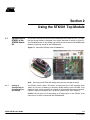
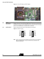
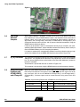
The STK501 should be connected to the STK500 expansion header 0 and 1. It is important that the top module is connected in the correct orientation as shown in Figure 2-1.
The EXPAND0 written on the STK501 top module should match the EXPAND0 written
beside the expansion header on the STK500 board.
Figure 2-1. Connecting STK501 to the STK500 Board
Note:
2.1.1
Placing an
ATmega103(L) or
ATmega128(L) on
the STK500
Connecting the STK501 with wrong orientation may damage the board.
The STK501 contains both a ZIF socket, and the pinout for a TQFP package; which
allows an easy way of soldering an emulator adapter directly into the STK501. Care
should be taken so that the device (or adapter) is mounted with the correct orientation.
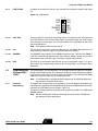
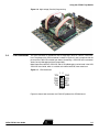
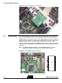
Figure 2-2 shows the location of pin 1 for the ZIF socket and the TQFP footprint.
Caution: Do not mount an ATmega103(L) or ATmega128(L) on the STK501 at the
same time as an AVR is mounted on the STK500 board.
AVR® STK501 User Guide
2-1
Rev. 2491A-09/01