1
Using the STK501 Top Module
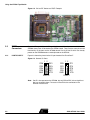
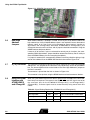
Figure 2-2. Pin1 on ZIF Socket and TQFP Footprint
2.2
PORT
Connectors
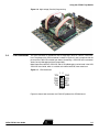
Since the ATmega103(L) and ATmega128(L) have additional ports not available on the
STK500, these ports are located on the STK501 board. They have the same pinout and
functionality as the ports on the STK500 board. Port A to Port D which are already
present on the STK500 board are not duplicated on the STK501.
2.2.1
PORT E/PORT F
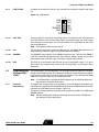
Figure 2-3 shows the pinout for the I/O port headers Port E and Port F.
Figure 2-3. General I/O Ports
1 2
1 2
PE0
PE2
PE4
PE6
GND
PE1
PE3
PE5
PE7
VTG
PORT E
Note:
2-2
PF0
PF2
PF4
PF6
GND
PF1
PF3
PF5
PF7
VTG
PORT F
Port E is also present on the STK500, but only PE0 to PE2 (3 least significant
bits) are accessible there. To access all Port E bits the connector on the
STK501 must be used.
AVR® STK501 User Guide