1
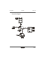
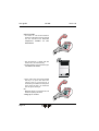
User guide
EX PBX
User guide
Issue 1.02
EX PBX
Universal interface for the
connection of 4 wire
doorspeakers with
PABX on analogue
T/R line
Page 1
User guide
EX PBX
Issue 1.02
Index
Description ............................................................................ 3
Connection diagram ............................................................. 5
View of the EX PBX universal door interface........................ 6
Features ................................................................................. 7
Installation ............................................................................ 7
Connection diagram ACI Farfisa doorstation .................... 10
Connection diagram SIEDLE doorstation ........................... 10
Connection diagram RITTO doorstation ............................. 11
Connection diagram GROTHE doorstation ......................... 11
Connection diagram LEGRAND TERRANEO doorstation ..... 12
Connection diagram URMET doorstation ........................... 12
How to use .......................................................................... 13
Technical data ..................................................................... 15
Page 2
User guide
EX PBX
Issue 1.02
Description
The universal interface EX PBX allows the connection of a standard 4 wire
doorspeaker to a T/R extension line of any PABX. The unit is delivered in a
plastic housing which allows the installation in a standard DIN electric
distribution cabinet.
The connection to the doorspeaker is done with three or four wires. In the
standard configuration the unit is used to connect an existing doorspeaker. In
this case the doorspeaker is powered by his own power supply, and only the
speach ways are to be connected to the EX PBX: microphone, loudspeaker
and the common ground. The microphone input is suitable for an
preamplified electronic microphone with his own power supply. The
loudspeaker output is provided for the connection of an amplified
doorspeaker. Also an carbon microphone can be connected to the unit, but
not within a multi user doorspeaker system. As the loudspeaker output has
also his own amplifier also a passiv loudspeaker can be connected to it. The
volume of loudspeaker output and microphone input can be regulated.
A four wire cabling is only required if the doorspeaker has to be powered by
the EX PBX itself. In this case the line for microphone, loudspeaker, common
ground and the 8 Vdc power suppy are to be connected. The 8 V dc voltage is
generated by an internal rectifier. This one is supplied by an external 12 Vac
voltage. The 8 Vdc voltage output is driven by the line sizeing, and is
available only during the off hook status. The connection of an external 12
Vac power supply is only needed if the generation of a 8 Vdc is required. The
EX PBX itself is entirly powered by the telephone line.
With the three wire connection you can install the unit in single user as well
multi user installations. Please note that the microphone circuit is in case of
the connection of an EX PBX always powered (if busy indications are provided
on the doorstation they will be on all the time!). These will not disturbe the
normal functionality. The unit has in a idle status an high impedance output
on the speach line, and the privacy is thus granted. Should the busy indicator
on the doorstation disturb you, you can use the 8 Vdc output to drive an
external relais which disconnects the ground to the doorstation in the idle
status. If the doorstation is powered by the EX PBX itself this problem will not
appare. The installation with a power supply from the EX PBX can be done
only with single user systems. As single user system we define an installation
were the doorstation is used by only one user. A multi user system is a
installation where the doorstation is used by more users (more PABX or one
PABX and more housephones).
Page 3
User guide
EX PBX
Issue 1.02
The unit is activated with the doorbell chime. Herefore a 12 Vac power
supply has to used (mostly common in multi user systems). With the
insertion of two internal jumpers also a function with a powerless key may
be possible. Please note that the LED is on only during the off hook status.
To the PABX the EX PBX is connected by using two wires to an analogue T/R
extension line. After applying a 12 Vac voltage on the chime key input, or by
closing the contact if a powerless function is installed, the unit will go off
hook. The LED will go on, the 8 Vdc voltage is delivered to the output (not
with powerless function, and only if a 12 Vac voltage was applied to the
proper input), and the programmed number is dialed on the line. A DTMF or
rotary dial can be selected on the unit. The telefon number is programmed by
setting the jumpers on the jumper groups J7 to J10. An up to 4 digit long
number can be programmed. J7 is the first dialed digit, J10 the last one. If on
a jumper group no number is setted, no number will be dialed. Each jumper
group defines one digit. The digits are programmed using a BCD hex code.
The numbers 1 to 0, as well the DTMF tones *, #, A, B and C can be
programmed.
If required the EX PBX can also be called. If a ring voltage is detected the unit
will answer at the first burst. After the answer the unit sends the
programmed number as a confirmation tone that the doorstation is now
connected. The unit can so be used also in connection of a standard door
chime. Is this case the normal door bell is called and the user can connect to
the doorstation by calling the universal interface. Please take care that if the
dial functionality is not used at least one number has to be programmed to
provide the connection confirmation tone.
During the connection using a DTMF dial pad telephone a door opener
contact can be activated dialing the "7". The door opener contact is activated
as long as the EX PBX detects the DTMF signal. If only one burst is detected
the door opener will be activated for 4 seconds.
The connection will be terminated as soon as a busy tone is surley detected.
The EX PBX can be released also dialing the DTMF digit "3" during the
connection. If the called party doesn't answer the unit will drop the
connection after 7 ringback tones. For the enhanced security the unit has also
a hardware timer. This will ensure that the connection is terminated in any
case after the time out. The time out can be set to 1, 2 or 4 minutes using
jumper which can be find inside the unit.
Page 4
User guide
EX PBX
Issue 1.02
Connection diagram
Page 5
User guide
EX PBX
Issue 1.02
View of the EX PBX universal door interface
Jumpers for powerless chime key setup
Loudspeaker
volume
Connection for
doorspeaker
Jumper for hardware time out
Telephone number set up
DTMF/rotary dial set up jumper
Line busy LED
Microphone volume
T/R line connection
Door chime button connection
Door opener contact connection
12 Vac voltage input (optional, see description)
Please note!
If a powerless button has to be used you must set the jumper and take the
piggy back unit inside the interface off.
In this case the 8 Vdc voltage is no more available to supply the doorspeaker.
Page 6
User guide
EX PBX
Issue 1.02
Features
- 1 to 4 digit long number dial
- High quality handsfree speach controlled unit
- Tone detection
- Automatic call answer
- Volume regulation for loudspeaker and microphone
- With DTMF dial controlled door opener contact
- Connection to any PABX T/R analogue extension line
- DTMF or rotary dial selectable
- Programmable time out timer
Installation
The EX PBX unit is designed to be installed in a electrical distribution cabinet
using standard DIN rails (9 DIN modul A). After the installation and cabling
using the following diagrams (if you cann't find the appropiate plan please
contact the Rocom service nearest to you or the Rocom Webside http://
www.rocom-gmbh.de) the number to be dialled has to be programmed. This
is done by setting the appropiate jumpers. The dialed number can be 1 to 4
digit long. The jumper setting can be saw on the following table. The first
digit is defined by the first group of four jumpers. The number is programmed
using a BCD hex code, where the lowest digit (2°) is the first jumper on the
right of each group of four. The number "0" is set as the hex code "A" (decimal
10). Digit which are not used are to be set empty (no jumpers). After the
programmation of the telephone number you should select the appropiate
dial mode for your PABX (default is DTMF). The unit is now ready to work. You
should set up a connection with the door unit. A regulation of the sending
and receiving volume may be necessary. To do this you should use the
regulators placed on the universal interface as well on the door speaker itself
to achive the best sound quality. Please take care to regulate VERY carefully. If
this is done by two people this might be helpful. If the loudspeaker send
only "broken" tones, or it has a too low volume, changing the volume of
the microphone on the EX PBX may help.
With the installation within a multi user system it might be necessary to
reduce the incoming microphone signal level. To do this you might insert a
Page 7
User guide
EX PBX
J7 (X000)
1
J8 (0X00)
X
2
X
3
X
4
X
5
X
6
X
X
7
X
X
Issue 1.02
J9 (00X0)
X
X
X
X
X
X
X
8
X
9
X
0
X
X
*
X
X
#
X
X
A
X
X
B
X
X
X
C
X
X
X
X
X
X
X
X
X
X
X
X
X
X
X
X
X
X
X
X
X
X
X
X
X
X
X
X
X
X
X
X
X
X
X
X
X
X
X
X
X
X
X
X
X
X
X
X
X
X
X
X
X
X
J10 (000X)
X
X
X
X
X
X
X
X
X
X
X
X
X
X
X
X
X
X
X
X
X
X
X
X
X
X
X
X
X
X
X
X
X
X
X
X
X
X
X
X
X
X
X
X
X
1 or 2 KOHm resistance on the microphone line.
With a very loud external enviroment the unit may be have difficulties
detecting the busy tone. This may happen also with tone which are not
within the values as indicated in the technical specification at the end of this
document. In this case you should use always the dial of the digit "3" to
terminate the connection.
The door chime button input needs a 12 Vac voltage to be activated. If the
jumpers P1 and P2 (to be find inside the unit, below piggy back unit) are set,
and the piggy back unit is taked off, also a powerless button may be
Page 8
User guide
EX PBX
Issue 1.02
connected to the unit.
With the door chime you should take care to not connect electromecanical gongs or bells parallel to the EX PBX. These can generate very
high noise voltage which may destroy the unit. If you need another bell to be
activated together with the universal interface you should use only electronic
devices or a relais.
Please take care if using a bell transformator for the power supply, to use one
with a no carge voltage not higher then 15Vpp. We suggest the use of the
ACI Farfisa PRS 210 transformator.
Please note that only one door opener with 40 Vpp and 2 A can be connected
to the unit. If you need to drive more door openers or if you need an higher
voltage or current you should use a relais. We suggest the use of the ACI
Farfisa relais 1471.
Furthermore please consider this for the installation:
- If you are using digital sets or featurphones on your PABX please take care
that these are enabled to send DTMF tones also after an incoming call. You
need this to open the door.
- The installation of more then one EX PBX with the same doorstation is
not possible. You can connect more doorstation using more EX PBX in
the same system only if each doorstation has his own power supply
unit. Every unit connected to the EX PBX has to have a class II power
supply unit (no safety grounding) as far as the connected PABX has a
class I power supply (safety ground).
Page 9
User guide
EX PBX
Connection diagram ACI Farfisa doorstation
Connection diagram SIEDLE doorstation
Page 10
Issue 1.02
User guide
EX PBX
Issue 1.02
Connection diagram RITTO doorstation
Please note!
The
connections +
and + have to
be separated!
Connection diagram GROTHE doorstation
Page 11
User guide
EX PBX
Issue 1.02
Connection diagram LEGRAND BTICINO doorstation
Do orsp eaker
SM 5 0X ,26 59N
2
1
+
+
N
230 VAC
TELEF
TELEF
L
DOOR
Ru fta sten mo d ul
SM 4 0X ,21 4X
DO
DOOR
~
Doorstation Line 1000,
Ters ystem
Power supply 672
Universal interface
EX PBX
Connection diagram URMET doorstation
Page 12
TO THE PABX
(T/R extension l ine)
User guide
EX PBX
Issue 1.02
How to use
Call from outside
- The visitor presses the bell button
- The line is sized and the programmed
number is dialed
- The extension is called
- On the doorspeaker the visitor can
hear a ringback tone
- If you are busy or you can't answer
within seven calls the line will be
automaticaly dropped
- As soon as you answers the call you
can talk to the visitor at the door
- At the end of the conversation press
the key 7 to open the door. The
opener will be activated for 4
seconds. If you need more time press
more times the key 7. To terminate
the call press the key 3.
OR
- Press the key 3 to terminate the call
without opening the door
- Hang up the handset
Page 13
User guide
EX PBX
Call from inside
- You want to call the doorstation
without a call being set from outside
- Lift the handset and dial the
telephone number of the
doorstation
- The doorstation is called and will
answer the call automaticaly
- The doorspeaker is activated and you
can talk to the visitor
- At the end of the conversation press
the key 7 to open the door. The
opener will be activated for 4
seconds. If you need more time press
more times the key 7. To terminate
the call press the key 3.
OR
- Press the key 3 to terminate the call
without opening the door
- Hang up the handset
Page 14
Issue 1.02
User guide
EX PBX
Issue 1.02
Technical data
Power supply
Telephone line voltage
Voltage insertion drop on T/R
Current consumption
Telephone line impedance
Doorspeaker power supply
Dial mode
Rotary dial
DTMF dial
Tone recognition
Door opener
Time out
Enviromental themperature
EMC
Security
Dimensions
from telephone line
min. 24 Vdc, max. 60 Vdc
10 V +/- 5% at 25 mA
off hook: min. 18 mA
stand-by: 2 µA
600 Ohm
Input: 12 Vac to max. 18 Vac
Input with overvoltage and overcurrent protection
Output: 8 Vdc max. 200 mA, drived by line seizure
rotary dial, DTMF selectable
impulse frequency: 10 Hz
dial pause: 820 ms
impulse duration: 60 ms
impulse pause: 40 ms
open line resistance: > 300 KOhm
standard DTMF
Tone duration: 70 ms
Tone pause: 70 ms
detectable tone frequency: 390 to 480 Hz
detectable ringback tone: tone duration from 770 to
1100 ms. Release after 7/8
tones
detectable long busy tone: tone duration from 170 to
550 ms. Release after 5/6
tones
detectable short busy tone: tone duration from 70 to
150 ms. Release after 10/11
tones
DTMF digit "7"
Min. detectable DTMF tone duration: 45 to 50 ms
Max. contact load: 40 Vpp, 2 A
Closure duration: 4,5 seconds (or as long as a DTMF 7
digit is detected)
1, 2 or 4 minutes selectable
0° to 45° C
EN 60555-2
EN 55022
EN 50082-1
EN 60950
158 x 89 x 57 mm (l x h x d) DIN rail case 9 DIN A
Module
Page 15
© 2000 ROCOM GmbH. Product may change without notice. We do not respond for any errors or mistake in the present documentation.
Printed in Germany.
User guide
Page 16
EX PBX
Your dealer:
Made by:
Energie- und Kommunikationssysteme GmbH
Lessing Str. 20, 63110 Rodgau, Germany
Tel. +49-6106-6600-0 Fax +49-6106-6600-66
E-Mail: [email protected]
http://www.rocom-gmbh.de
Issue 1.02