1
XLP 16-Bit Development Kit
User’s Guide
© 2009 Microchip Technology Inc.
DS51873A
Note the following details of the code protection feature on Microchip devices:
•
Microchip products meet the specification contained in their particular Microchip Data Sheet.
•
Microchip believes that its family of products is one of the most secure families of its kind on the market today, when used in the
intended manner and under normal conditions.
•
There are dishonest and possibly illegal methods used to breach the code protection feature. All of these methods, to our
knowledge, require using the Microchip products in a manner outside the operating specifications contained in Microchip’s Data
Sheets. Most likely, the person doing so is engaged in theft of intellectual property.
•
Microchip is willing to work with the customer who is concerned about the integrity of their code.
•
Neither Microchip nor any other semiconductor manufacturer can guarantee the security of their code. Code protection does not
mean that we are guaranteeing the product as “unbreakable.”
Code protection is constantly evolving. We at Microchip are committed to continuously improving the code protection features of our
products. Attempts to break Microchip’s code protection feature may be a violation of the Digital Millennium Copyright Act. If such acts
allow unauthorized access to your software or other copyrighted work, you may have a right to sue for relief under that Act.
Information contained in this publication regarding device
applications and the like is provided only for your convenience
and may be superseded by updates. It is your responsibility to
ensure that your application meets with your specifications.
MICROCHIP MAKES NO REPRESENTATIONS OR
WARRANTIES OF ANY KIND WHETHER EXPRESS OR
IMPLIED, WRITTEN OR ORAL, STATUTORY OR
OTHERWISE, RELATED TO THE INFORMATION,
INCLUDING BUT NOT LIMITED TO ITS CONDITION,
QUALITY, PERFORMANCE, MERCHANTABILITY OR
FITNESS FOR PURPOSE. Microchip disclaims all liability
arising from this information and its use. Use of Microchip
devices in life support and/or safety applications is entirely at
the buyer’s risk, and the buyer agrees to defend, indemnify and
hold harmless Microchip from any and all damages, claims,
suits, or expenses resulting from such use. No licenses are
conveyed, implicitly or otherwise, under any Microchip
intellectual property rights.
Trademarks
The Microchip name and logo, the Microchip logo, dsPIC,
KEELOQ, KEELOQ logo, MPLAB, PIC, PICmicro, PICSTART,
rfPIC and UNI/O are registered trademarks of Microchip
Technology Incorporated in the U.S.A. and other countries.
FilterLab, Hampshire, HI-TECH C, Linear Active Thermistor,
MXDEV, MXLAB, SEEVAL and The Embedded Control
Solutions Company are registered trademarks of Microchip
Technology Incorporated in the U.S.A.
Analog-for-the-Digital Age, Application Maestro, CodeGuard,
dsPICDEM, dsPICDEM.net, dsPICworks, dsSPEAK, ECAN,
ECONOMONITOR, FanSense, HI-TIDE, In-Circuit Serial
Programming, ICSP, Mindi, MiWi, MPASM, MPLAB Certified
logo, MPLIB, MPLINK, mTouch, Octopus, Omniscient Code
Generation, PICC, PICC-18, PICDEM, PICDEM.net, PICkit,
PICtail, PIC32 logo, REAL ICE, rfLAB, Select Mode, Total
Endurance, TSHARC, UniWinDriver, WiperLock and ZENA
are trademarks of Microchip Technology Incorporated in the
U.S.A. and other countries.
SQTP is a service mark of Microchip Technology Incorporated
in the U.S.A.
All other trademarks mentioned herein are property of their
respective companies.
© 2009, Microchip Technology Incorporated, Printed in the
U.S.A., All Rights Reserved.
Printed on recycled paper.
Microchip received ISO/TS-16949:2002 certification for its worldwide
headquarters, design and wafer fabrication facilities in Chandler and
Tempe, Arizona; Gresham, Oregon and design centers in California
and India. The Company’s quality system processes and procedures
are for its PIC® MCUs and dsPIC® DSCs, KEELOQ® code hopping
devices, Serial EEPROMs, microperipherals, nonvolatile memory and
analog products. In addition, Microchip’s quality system for the design
and manufacture of development systems is ISO 9001:2000 certified.
DS51873A-page 2
© 2009 Microchip Technology Inc.
XLP 16-BIT DEVELOPMENT KIT
USER’S GUIDE
Table of Contents
Preface ........................................................................................................................... 5
Chapter 1. Introduction to the XLP 16-Bit Board
1.1 Introduction ................................................................................................... 11
1.2 Highlights ...................................................................................................... 11
1.3 What’s in the Kit ........................................................................................... 12
1.4 Development Board Features ...................................................................... 12
1.5 Using the Development Board Out of the Box ............................................. 13
1.6 Demonstration Program ............................................................................... 13
1.7 Reference Documents .................................................................................. 14
Chapter 2. The XLP Demonstration Application
2.1 Initial Setup ................................................................................................... 15
2.2 Demonstration Program Operation .............................................................. 17
Chapter 3. XLP 16-Bit Development Board Hardware
3.1 Introduction ................................................................................................... 21
3.2 Hardware Features ....................................................................................... 21
3.3 Current Measurement .................................................................................. 27
Appendix A. Development Kit Schematics ............................................................... 29
Index ............................................................................................................................. 35
Worldwide Sales and Service .................................................................................... 36
© 2009 Microchip Technology Inc.
DS51873A-page 3
XLP 16-Bit Development Kit User’s Guide
NOTES:
DS51873A-page 4
© 2009 Microchip Technology Inc.
XLP 16-BIT DEVELOPMENT KIT
USER’S GUIDE
Preface
NOTICE TO CUSTOMERS
All documentation becomes dated, and this manual is no exception. Microchip tools and
documentation are constantly evolving to meet customer needs, so some actual dialogs
and/or tool descriptions may differ from those in this document. Please refer to our web site
(www.microchip.com) to obtain the latest documentation available.
Documents are identified with a “DS” number. This number is located on the bottom of each
page, in front of the page number. The numbering convention for the DS number is
“DSXXXXXA”, where “XXXXX” is the document number and “A” is the revision level of the
document.
For the most up-to-date information on development tools, see the MPLAB® IDE on-line help.
Select the Help menu, and then Topics to open a list of available on-line help files.
INTRODUCTION
This chapter contains general information that will be useful to know before using the
XLP 16-Bit Development Board. Items discussed in this chapter include:
•
•
•
•
•
•
•
•
Document Layout
Conventions Used in this Guide
Warranty Registration
Recommended Reading
The Microchip Web Site
Development Systems Customer Change Notification Service
Customer Support
Document Revision History
DOCUMENT LAYOUT
This document describes how to use the XLP 16-Bit Development Board as a development tool to emulate and debug firmware on a target board. The manual layout is as
follows:
• Chapter 1. Introduction to the XLP 16-Bit Board provides a brief overview of
the XLP 16-Bit Development Board, its features and its uses
• Chapter 2. The XLP Demonstration Application describes the preprogrammed
demonstration program
• Chapter 3. XLP 16-Bit Development Board Hardware provides a more detailed
description of the XLP 16-bit board’s hardware features
• Appendix A. Development Kit Schematics provides detailed schematics of the
XLP 16-Bit Development Board
© 2009 Microchip Technology Inc.
DS51873A-page 5
XLP 16-Bit Development Kit User’s Guide
CONVENTIONS USED IN THIS GUIDE
This manual uses the following documentation conventions:
DOCUMENTATION CONVENTIONS
Description
Arial font:
Italic characters
Represents
Referenced books
Emphasized text
A window
A dialog
A menu selection
A field name in a window or
dialog
A menu path
MPLAB® IDE User’s Guide
...is the only compiler...
the Output window
the Settings dialog
select Enable Programmer
“Save project before build”
A dialog button
A tab
A key on the keyboard
Click OK
Click the Power tab
Press <Enter>, <F1>
Italic Courier New
Sample source code
Filenames
File paths
Keywords
Command-line options
Bit values
Constants
A variable argument
Square brackets [ ]
Optional arguments
Curly brackets and pipe
character: { | }
Ellipses...
Choice of mutually exclusive
arguments; an OR selection
Replaces repeated text
#define START
autoexec.bat
c:\mcc18\h
_asm, _endasm, static
-Opa+, -Opa0, 1
0xFF, ‘A’
file.o, where file can be
any valid filename
mcc18 [options] file
[options]
errorlevel {0|1}
Initial caps
Quotes
Underlined, italic text with
right angle bracket
Bold characters
Text in angle brackets < >
Courier New font:
Plain Courier New
Represents code supplied by
user
DS51873A-page 6
Examples
File>Save
var_name [,
var_name...]
void main (void)
{ ...
}
© 2009 Microchip Technology Inc.
Preface
WARRANTY REGISTRATION
Please complete the enclosed Warranty Registration Card and mail it promptly.
Sending in the Warranty Registration Card entitles users to receive new product
updates. Interim software releases are available at the Microchip web site.
RECOMMENDED READING
This user’s guide describes how to use XLP 16-Bit Development Board. Other useful
documents are listed below. The following Microchip documents are available and
recommended as supplemental reference resources.
Readme for XLP 16-Bit Development Board
For the latest information on using the XLP 16-Bit Development Board, refer to the file
readme.pdf in the “XLP 16-Bit Development Board Demo” subdirectory of the installation directory. This file contains update information and known issues that may not be
included in this user’s guide.
PIC24F16KA102 Family Data Sheet (DS39927)
Consult this document for detailed information on the PIC24F K-series Flash device
that is pre-installed in the development kit. Reference information found in this data
sheet includes:
•
•
•
•
Device memory map
Device pinout and packaging details
Device electrical specifications
List of peripherals included on the device
PIC24F Family Reference Manual
This reference manual explains the operation of the PIC24F microcontroller family
architecture and peripheral modules. The specifics of each device family are discussed
in the individual family’s device data sheet.
This useful manual is on-line in sections at the Technical Documentation section of the
Microchip web site. Refer to these sections for detailed information on PIC24F device
operation.
16-Bit MCU and DSC Programmer’s Reference Manual (DS70157)
This manual is a software developer’s reference for all of Microchip’s 16-bit
microcontrollers. It describes the instruction set in detail and also provides general
information to assist in developing software for PIC24, dsPIC30 and dsPIC33 MCUs.
© 2009 Microchip Technology Inc.
DS51873A-page 7
XLP 16-Bit Development Kit User’s Guide
THE MICROCHIP WEB SITE
Microchip provides online support via our web site at www.microchip.com. This web
site is used as a means to make files and information easily available to customers.
Accessible by using your favorite Internet browser, the web site contains the following
information:
• Product Support – Data sheets and errata, application notes and sample
programs, design resources, user’s guides and hardware support documents,
latest software releases and archived software
• General Technical Support – Frequently Asked Questions (FAQs), technical
support requests, online discussion groups, Microchip consultant program
member listing
• Business of Microchip – Product selector and ordering guides, latest Microchip
press releases, listing of seminars and events, listings of Microchip sales offices,
distributors and factory representatives
DEVELOPMENT SYSTEMS CUSTOMER CHANGE NOTIFICATION SERVICE
Microchip’s customer notification service helps keep customers current on Microchip
products. Subscribers will receive e-mail notification whenever there are changes,
updates, revisions or errata related to a specified product family or development tool of
interest.
To register, access the Microchip web site at www.microchip.com, click on Customer
Change Notification and follow the registration instructions.
The Development Systems product group categories are:
• Compilers – The latest information on Microchip C compilers and other language
tools. These include the MPLAB® C18 and MPLAB C30 C compilers; MPASM™
and MPLAB ASM30 assemblers; MPLINK™ and MPLAB LINK30 object linkers;
and MPLIB™ and MPLAB LIB30 object librarians.
• Emulators – The latest information on Microchip in-circuit emulators.This
includes the MPLAB ICE 2000 and MPLAB ICE 4000.
• In-Circuit Debuggers – The latest information on the Microchip in-circuit
debugger, MPLAB ICD 2.
• MPLAB® IDE – The latest information on Microchip MPLAB IDE, the Windows®
Integrated Development Environment for development systems tools. This list is
focused on the MPLAB IDE, MPLAB SIM simulator, MPLAB IDE Project Manager
and general editing and debugging features.
• Programmers – The latest information on Microchip programmers. These include
the MPLAB PM3 and PRO MATE® II device programmers and the PICSTART®
Plus and PICkit™ 1 development programmers.
DS51873A-page 8
© 2009 Microchip Technology Inc.
Preface
CUSTOMER SUPPORT
Users of Microchip products can receive assistance through several channels:
•
•
•
•
Distributor or Representative
Local Sales Office
Field Application Engineer (FAE)
Technical Support
Customers should contact their distributor, representative or field application engineer
(FAE) for support. Local sales offices are also available to help customers. A listing of
sales offices and locations is included in the back of this document.
Technical support is available through the web site at: http://support.microchip.com
DOCUMENT REVISION HISTORY
Revision A (October 2009)
• Initial Release of this Document.
© 2009 Microchip Technology Inc.
DS51873A-page 9
XLP 16-Bit Development Kit User’s Guide
NOTES:
DS51873A-page 10
© 2009 Microchip Technology Inc.
XLP 16-BIT DEVELOPMENT KIT
USER’S GUIDE
Chapter 1. Introduction to the XLP 16-Bit Board
1.1
INTRODUCTION
Thank you for purchasing Microchip Technology’s XLP 16-Bit Development Board Kit.
The board provides a low-cost, highly configurable development system for Microchip’s
new line of PIC24F 28 and 20-pin Extreme Low-Power (XLP) microcontrollers,
including the PIC24F16KA102 and PIC24FJ64GA102 families.
The XLP 16-bit board permits users to explore and evaluate extreme low-power
features, and learn low-power software and hardware techniques. Various headers are
available to measure both microcontroller and component power consumption. It is
flexible, supporting six different power sources over a wide voltage range. It is highly
configurable, equipped with a variety of common peripheral components that can be
selectively enabled. Finally, it is expandable through its modular interface, providing for
the addition of advanced interfaces and connectivity methods.
As provided, the XLP 16-Bit Development Board functions as a demonstration platform
on initial power-up. The included demonstration software takes a temperature
measurement, datalogs information to the serial data EEPROM and displays information to a host PC via a USB connection. Additional software is provided to demonstrate
low-power techniques and IC interface routines.
1.2
HIGHLIGHTS
The XLP 16-Bit Development Board includes these features:
• Support for both 20-pin and 28-pin versions of both PIC24F J-series and K-series
Flash microcontrollers
• Accommodations for six different power source options
• Configurability for a wide range of operating voltages (1.8V to 5.5V)
• Configuration selection jumpers to disable board components
• A hardware-switchable option to control power to board components with port pin
• USB connectivity
• Provisions to add RS-232 transceivers (not populated)
• 5 user-defined buttons (3 capacitive touch and 2 push buttons)
• Two user-defined LEDs
• Two temperature sensors
• Potentiometer for analog input or High/Low Voltage Detect (HLVD) reference
• Built-in capability for separately measuring microcontroller and component current
consumption
• Support for all Microchip compatible programmers and emulators
© 2009 Microchip Technology Inc.
DS51873A-page 11
XLP 16-Bit Development Kit User’s Guide
1.3
WHAT’S IN THE KIT
The XLP 16-Bit Development Board Kit includes the following:
• XLP 16-Bit Development Board with a preprogrammed PIC24F16KA102
microcontroller installed
• USB mini-B cable
1.4
DEVELOPMENT BOARD FEATURES
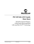
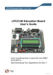
A layout of the XLP 16-Bit Development Board is shown in Figure 1-1. The board
includes these specific features, as indicated in the diagram:
1. Shared footprint 20-pin and 28-pin (300 mil DIP) sockets for PIC24F
microcontrollers, plus associated headers
2. Oscillator circuits (8 MHz and 32.768 kHz) for PIC24F microcontrollers
3. Power supply area (battery holders, external power supply input, LDO regulator
and power supply select jumper)
a) Interface headers for energy harvester demonstration kits
4. IC power control switch (IC PWR)
5. Power LED
6. Adjustable LDO regulator
7. PIC24F on-chip regulator configuration switch and circuitry
8. IC power select jumpers
9. PIC24F Master Clear switch
10. Capacitive touch pads
11. User-defined push buttons
12. Potentiometer
13. User-defined LEDs
14. Serial EEPROM
15. Temperature sensors
16. Capacitive measurement point
17. USB interface (USB/UART transceiver, PIC18F oscillator and USB port)
18. Unpopulated RS-232 options area
19. Programming interfaces:
a) MPLAB ICD 2 6-wire interface (RJ-11 socket) and separate PIC18 ICSP™
header
b) PICkit™ programmer 6-pin interface
20. Modular 28-pin riser interface for daughter boards
21. Prototype area with supply voltage and I2C™ signal access
22. Current measurement jumpers and access point
A more detailed discussion of each feature and its configuration is provided in
Section Chapter 3. “XLP 16-Bit Development Board Hardware”.
DS51873A-page 12
© 2009 Microchip Technology Inc.
Introduction to the XLP 16-Bit Board
FIGURE 1-1:
XLP 16-BIT BOARD COMPONENT LAYOUT
3
21
22
5
6
8
4
17
16
19a
9
2
3a
7
1
15
14
20
12
18
11
13
M
10
19b
1.5
USING THE DEVELOPMENT BOARD OUT OF THE BOX
Although intended as a development platform, the XLP 16-bit board may also be used
directly from the box as a demonstration platform for the preprogrammed
PIC24F16KA102 microcontroller.
Refer to Chapter 2. “The XLP Demonstration Application” for details on the
demonstration code operation.
© 2009 Microchip Technology Inc.
DS51873A-page 13
XLP 16-Bit Development Kit User’s Guide
1.6
DEMONSTRATION PROGRAM
The preprogrammed example code on the PIC24F16KA102 device is available for
download from the Microchip web site (www.microchip.com/XLP16BitBoard). All
required project files are provided, so that the code may be used as an example or a platform for further development. These may be used with the included PIC24F16KA102
device by programming the device using an MPLAB ICD 2 programmer/debugger,
PICkit™ starter kit or any other Microchip programming tool.
In addition, the firmware for the USB-to-serial emulator that is preloaded on the
PIC18F14K50 microcontroller, is also provided. Both source code (in C) and compiled
code files (in HEX format) are included.
1.7
REFERENCE DOCUMENTS
In addition to the documents listed in the “Recommended Reading” section, these documents are also available from Microchip to support the use of the XLP 16-Bit
Development Board:
• “25AA256/25LC256 256K SPI Bus Serial EEPROM” Data Sheet (DS21822)
• “MCP9700/9700A/9701/9701A Low-Power Linear Active Thermistor™ ICs” Data
Sheet (DS21942)
• “PICkit™ 2 Programmer/Debugger User’s Guide” (DS51553)
• “PICkit™ 3 Programmer/Debugger User’s Guide” (DS51795)
• “MPLAB® ICD 2 In-Circuit Debugger Quick Start Guide” (DS51268)
• “MPLAB® REAL ICE™ In-Circuit Emulator User’s Guide” (DS51616)
• “Compiled Tips ‘n Tricks Guide” (DS01146)
• “PIC24F Family Reference Manual”, Section 11: Charge Time Measurement Unit
(CTMU) (DS39724)
DS51873A-page 14
© 2009 Microchip Technology Inc.
XLP 16-BIT DEVELOPMENT KIT
USER’S GUIDE
Chapter 2. The XLP Demonstration Application
This chapter describes the demonstration application that is preprogrammed on the
PIC24F microcontroller, which shows the use of low-power techniques in a working
application. In the process, the application highlights various features of the PIC24F
microcontroller family.
2.1
INITIAL SETUP
Although intended as a development platform, the XLP 16-bit board is also designed
to be used directly from the box as a demonstration platform. The demonstration
firmware preprogrammed into the PIC24F16KA102 microcontroller is ready for
immediate use.
Apart from the USB-to-serial driver, no special software is required to use the
development board. For users with a PC running Microsoft® Windows®, all that is
required is a serial terminal program; this is almost always installed with Windows in
the form of HyperTerminal. It is recommended that the driver files be downloaded from
the Microchip web site and saved to a convenient directory before proceeding.
2.1.1
Configuring and Connecting the Hardware
To get started with the board, verify that it is properly configured:
1. Verify the PIC24F16KA102 is correctly installed into socket, U1. The notch on the
edge of the device package will be toward the top of the board.
2. Verify that S4 is in the “PIC24K” position.
3. Ensure the IC PWR switch is in the “RB2” position.
4. Populate the PIC PWR and IC PWR jumpers.
5. Select “EXT PS/USB” with the power source select jumper.
6. Select the “MCP9700” temperature sensor option with the temp sense jumper.
7. Populate the TEMP, SEE and POT jumpers.
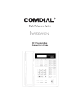
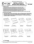
Once configured, connect the provided USB cable (A to mini-B) to any available USB
port on the PC or powered hub, then to the board at the mini-B receptacle, J9
(Figure 2-1). The PC USB connection provides communication and power to the board.
If the cable is connected correctly, the green power LED (D5) is lit.
2.1.2
Installing the Driver
At this point, one or more pop-up balloons in the system tray (lower right of desktop)
should appear, stating that the “CDC RS-232 Emulator Demo” device has been found.
The “Found New Hardware Wizard” dialog also appears. To continue:
1. Select the option “Install from a list or specific location” and Click Next.
2. In the following dialogs, browse to the location where the USB driver has been
saved.
3. Click through the subsequent dialogs as the driver installs.
Note:
© 2009 Microchip Technology Inc.
For Windows XP, one or more dialogs may warn that the driver has not
been digitally signed. This is normal. Click OK to proceed through the
dialogs.
DS51873A-page 15
XLP 16-Bit Development Kit User’s Guide
FIGURE 2-1:
STARTER KIT SETUP
A to mini-B USB Cable
Development Board
M
After the driver has installed, it is necessary to determine the COM port number that
has been assigned. To do this, open Device Manager (from the Control Panel, click on
the System applet, select the Hardware tab, then click on Device Manager). In the
default view (Device by Connection), check under “Ports (COM & LPT)” for the newly
added COM port. The actual number of the new COM port will vary, depending on the
hardware configuration of the system prior to driver installation.
2.1.3
Configuring the Serial Terminal
With the board connected and the USB driver installed, the only remaining task is to
configure the terminal session. The process described here is for HyperTerminal; other
terminal software may vary.
1. Launch HyperTerminal (typically, from the Start Menu, Programs >
Accessories > Communications > HyperTerminal).
2. At the initial Terminal window, the Connection Description pop-up dialog
appears. Select a name and icon for your connection session and choose a custom icon, then click OK. Use any convenient name that you choose. (This step
is not mandatory, but it makes connecting to the serial port much easier. If you
choose not to do this, click Cancel.)
3. At the Connection Properties dialog, select the COM port that was installed
with the driver from the Connect Using drop-down list. Click OK.
4. At the subsequent COM Properties dialog, change the settings to:
a) Bits per second: 38400
b) Data Bits: 8
c) Parity: None
d) Stop Bits: 1
e) Flow Control: None
5. Click OK to save the settings and close the COM dialog, then click OK to close
the Properties dialog.
Note:
If you are using another serial terminal, follow its normal session configuration
procedure. Be sure to use the settings in step 4 (above).
At this point, the terminal is connected to the XLP board and communicating through
the emulated serial port. It may be necessary to press S1 (Master Clear) to reset to the
PIC24F microcontroller and obtain a display.
DS51873A-page 16
© 2009 Microchip Technology Inc.
The XLP Demonstration Application
2.2
DEMONSTRATION PROGRAM OPERATION
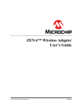
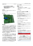
The demonstration program uses the on-board RS232-to-USB converter to send system status data in serial form to a standard serial terminal (Figure 2-2). It permits the
user to select which sensor information is displayed and to choose the microcontroller’s
low-power mode. This permits users to experiment with various low-power and XLP
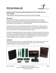
techniques, as well as make direct measurements.The program flow is shown in
Figure 2-3.
FIGURE 2-2:
SERIAL TERMINAL DISPLAY FOR THE DEMONSTRATION
APPLICATION
On power-up, the PIC24F16KA102 device will wake-up every 10 seconds from a
Real-Time Clock Calendar (RTCC) interrupt, then re-enter Sleep mode. While awake,
the microcontroller takes a temperature measurement using the MCP9700 temperature sensor and writes the information to the serial EEPROM. Status information is displayed, including the wake-up source, low-power mode, selected sensor, data
EEPROM information and current temperature. In the default POR configuration, the
RTCC interrupt is the wake-up source, while the MCP9700 is the active sensor.
Push button switches, S2 and S3, select the active sensors and desired low-power
mode, respectively. To minimize power, these switches use internal pull-ups which are
disabled in software when not in use.
Pressing S2 forces a sample to be taken immediately on the selected sensor. This
information is displayed on the HyperTerminal window.
Pressing S3 disables the output to the screen. This permits power measurements without the additional current consumed by the UART. Pressing S3 again enables the
UART and permits information to be displayed again.
Pressing and holding S2 for more than two seconds selects the sensor input. Repeated
presses cycle between the temperature sensor, potentiometer, capacitive touch pads
and all three sensors at once. The display reflects each new sensor selection. When
the potentiometer is selected, both VDD and current potentiometer voltages are shown.
When the touch pads are selected, their real-time status is displayed. When all three
sources are active at once, all of the sensor information is displayed at one time.
© 2009 Microchip Technology Inc.
DS51873A-page 17
XLP 16-Bit Development Kit User’s Guide
FIGURE 2-3:
DEMO APPLICATION SOFTWARE FLOW
Reset
Process Wake-up
or Reset Source
Button Press?
S2 Press
S2 Hold
Force
Sample
Switch Active
Sensor
N
S3 Press
S3 Hold
Toggle
UART
Transmit
Switch
Low-Power
Mode
S2 and S3 Hold
Transmit
Stored
EEPROM
Data
Sample Active
Sensors
Store Sensor Data
to EEPROM
UART
Enabled?
Y
Transmit
Current
Sensor Data
N
Enter Low-Power
Mode
DS51873A-page 18
© 2009 Microchip Technology Inc.
The XLP Demonstration Application
When the capacitive sense pads are active, the device wakes up more often (once per
second). In addition, data is only stored to the EEPROM when a capacitive touch event
is detected. The same is true when all sensors are active.
Pressing and holding S3 for more than two seconds selects between Sleep, Deep
Sleep and Idle modes for the PIC24 microcontroller. In Deep Sleep, most microcontroller functions are disabled to minimize power consumption. The available
wake-up sources supported by the XLP 16-Bit Development Board are RTCC interrupt,
External Interrupt 0 (INT0) and MCLR Reset. When Idle mode is selected, all peripherals continue to operate; however, program memory is disabled and code execution is
stopped to reduce power consumption.
Because of the limited number of wake-up sources available in Deep Sleep mode, S3
can not wake the microcontroller. However, S1 (MCLR Reset) and S2 (connected to
INT0), can wake up the device. The RTCC interrupt will continue to periodically
wake-up the microcontroller every 10 seconds. The display indicates which wake-up
source is used to exit Deep Sleep mode.
Note:
While the capacitive touch pads are enabled, the demo application will
enter Sleep mode instead of Deep Sleep; this permits the touch pads to
remain active and exit the low-power mode.
Pressing and holding S2 and S3 together, for more than two seconds, displays the
EEPROM’s contents. This consists of a data log of date/time entries from the RTCC
and the simultaneous sensor measurement.
© 2009 Microchip Technology Inc.
DS51873A-page 19
XLP 16-Bit Development Kit User’s Guide
NOTES:
DS51873A-page 20
© 2009 Microchip Technology Inc.
XLP 16-BIT DEVELOPMENT KIT
USER’S GUIDE
Chapter 3. XLP 16-Bit Development Board Hardware
3.1
INTRODUCTION
This chapter provides a more detailed description of the hardware features of the XLP
16-Bit Development Board.
3.2
HARDWARE FEATURES
The key features of the XLP 16-bit board are listed below. They are represented in the
order given in Section 1.4 “Development Board Features” and Figure 1-1.
3.2.1
PIC24F Processor Support
The XLP 16-bit board has been designed to accommodate PIC24F microcontrollers in
both 28-pin and 20-pin 300 mil DIP packages. All pin signals on both sockets are also
available for external monitoring on the 14-pin headers (J1 and J2), located on either
side of the sockets.
3.2.1.1
FEATURE AVAILABILITY BY PIC24F DEVICE FAMILY
The high degree of pin compatibility between PIC24F device families makes it possible
for the XLP 16-Bit Development Board to support many low pin count devices. However, there are a few minor pinout differences between families that make it difficult to
create a universal board. Of all of the board’s features described in this chapter, only
three are not universally available to all PIC24F microcontrollers. These are summarized in Table 3-1, with details provided in subsequent sections. Any feature that is not
listed here is implemented uniformly for all PIC24F device families that are supported
by the development board.
TABLE 3-1:
FEATURES THAT ARE NOT UNIVERSALLY AVAILABLE
PIC24F Device
Family
Board Feature
Potentiometer
D3 (Yellow)
28-Pin Modular
Connector
28-pin J series
(1)
N
Y
28-pin K-series
Y
Y
Y
20-pin K-series
Y
Y
N
Note 1:
3.2.2
Functions as an A/D potentiometer only on these devices, and as an A/D and
HVLD reference potentiometer on all others.
PIC24F Oscillator Options
The installed microcontroller has two separate oscillator circuits connected. The main
oscillator uses an 8 MHz crystal (Y1) and functions as the primary oscillator. A second
circuit, using a 32.768 kHz crystal (Y2), functions as the Timer1 oscillator and serves
as the source for the RTCC and secondary oscillator.
© 2009 Microchip Technology Inc.
DS51873A-page 21
XLP 16-Bit Development Kit User’s Guide
3.2.3
Power Sources
The XLP 16-bit board can use any one of six power options for full operation:
1. Bus power via the USB connector (J9). This provides a nominal 5V power
source, regulated to approximately 3.3V for the microcontroller and board components through a Schottky diode and low dropout regulator (LDO) circuit (D7,
Q1). The green power LED (D5) is illuminated when this power source is used
and bus power is present.
2. An unregulated supply of 9 VDC nominal (range of 5V to 12V) supplied to J6. For
default functionality, a center hot power supply with a current capability of
100 mA is sufficient. A larger power supply can be used, up to 700 mA, and may
be needed to support PICtail accessories. This voltage is fed into the on-board
regulator. The green power LED is illuminated when this power source is used
and power is present.
Note 1:
The XLP 16-Bit Development Kit does not include a power supply. If an
external supply is needed, use Microchip part number AC162039.
2:
The regulated power supply options are provided for easier development.
Power consumption by a regulator circuit is not included in board power
measurement.
3. Two AAA batteries (not included) installed in BT2. The output voltage is not regulated by the LDO, so the microcontroller and board run at the voltage provided by
the battery pair. To minimize current consumption, the power LED is not illuminated
for this power source.
4. A CR2032 coin cell battery (not included) installed in BT1. As with the AAA battery
option, the microcontroller and board run directly from the 3V nominal battery
voltage and the power LED is not illuminated.
5. Two headers (one 5-pin, one 6-pin 0.05” pitch) are provided to connect with external energy harvesting development systems. The headers are industry standard
sizes commonly used with energy harvesting applications. If you plan to use an
energy harvesting system, verify pin compatibility before proceeding.
6. An external, regulated DC power supply connected to the VDD SRC and one of
the GND test points. Voltage is supplied to board and microcontroller without voltage drops or voltage regulation; therefore, supply voltage must meet the voltage
requirements for the installed PIC24F device. The power LED does not illuminate
in this configuration.
The installed PIC24F16KA102 operates between 1.8V to 3.6V. Refer to the
appropriate device data sheet for other devices.
A four-way jumper block, POWER SOURCE SELECT (J12), selects the power supply
option. The available options are USB/EXT PWR, AAA, 2032 and HARVEST (methods
1 through 5, above). The default configuration (as shipped) is USB Power mode. The
jumper block does not control external power applied directly to the board (method 6),
since the test point is located in the circuit after the block.
3.2.3.1
COMPONENT POWER SWITCH
The component power switch IC PWR (S7) allows for software-enabled control of
power by the PIC24F device to many of the board components. When the switch is in
the “RB2” position, the RB2 port pin can control power to components using a
P channel FET switch (U3). This permits experimentation with a popular technique to
reduce an application’s power consumption and extend battery life.
When the switch in the “ON” position, component power is selected only by the
corresponding component select jumper. See Section 3.2.4 “Component Select
Jumpers” for additional information.
DS51873A-page 22
© 2009 Microchip Technology Inc.
XLP 16-Bit Development Board Hardware
3.2.3.2
POWER LED
The green power LED (D9) illuminates when power is supplied from either the external
9V power supply or the USB connector.
3.2.3.3
ADJUSTABLE SUPPLY VOLTAGES
The LDO regulator (Q1) is adjustable, and can support a wide voltage range for both
board component and microcontrollers. It can be configured between 1.8V to 5.5V by
changing the values of the voltage divider formed by R28 and R29. Typical values are
listed in Table 3-2. The equation relating the resistor values to target VDD is provided in
Figure A-3 of Section Appendix A. “Development Kit Schematics”. As shipped, the
LDO is configured to supply 3.3V.
The typical drop of the LDO is approximately 1.75V. Ensure the fixed power supply or
USB supply voltage exceeds the desired microcontroller voltage by at least this
amount.
Note:
Always verify that the voltage selected on the LDO meets the VDD
specification of the installed PIC24F device.
The performance of the MCP9700 and the LEDs is diminished at 1.8V operation. If
RS-232 communication is needed at 1.8V, populate the LTC2801 and associated
components. See Section 3.2.14 “RS-232 Serial Port Options” for more information.
TABLE 3-2:
RESISTOR VALUES FOR R28/R29 VOLTAGE DIVIDER
Component
3.2.3.4
Target VDD
1.8V
3.3V
5.0V
R28
150 Ω
120 Ω
75 Ω
R29
450 Ω
200 Ω
33 Ω
ON-CHIP REGULATOR CONFIGURATIONS (PIC24F J-SERIES)
The XLP 16-bit board supports multiple regulator configurations for PIC24F devices
with an internal voltage regulator. A slider switch (S4) allows the user to configure the
board for either J-series or K-series Flash devices. With switch, S4, in the “PIC24FJ”
position, the microcontroller’s internal voltage regulator is enabled by connecting a
pull-down resistor to the DISVREG pin and a 10 µF capacitor to the VCAP pin.
For PIC24F J-series devices, additional power savings can be achieved by disabling
the regulator. Three methods are supported by making several component changes to
the “PIC24F VREG” section of the PCB:
• Separate power supply for VDD and VDDCORE
• VDDCORE and VDD connected together
• VDDCORE connected through a zener diode to VDD
The required component changes are summarized in Table 3-3.
TABLE 3-3:
COMPONENT CHANGES FOR DISABLING ON-CHIP
REGULATOR
Component Placement and Value
J-series Regulator
Option
R3
Split VDD and VDDCORE
NP
Same VDD and VDDCORE
0Ω
VDDCORE Zener diode
NP
R4
R5
C4
D6
VCAP Test
Point
NP
VDDCORE
NP
1 kΩ
NP
NP
N/C
P
N/C
Legend: NP = not populated; P = populated.
© 2009 Microchip Technology Inc.
DS51873A-page 23
XLP 16-Bit Development Kit User’s Guide
3.2.4
Component Select Jumpers
A bank of jumpers is available to selectively enable various board components. These
jumpers, located in the “Power Control” block on the board, permit the user to perform
customized power management analysis and configure the board more closely to the
user’s application. By removing the jumper for a component, power is disconnected to
the designated IC and supporting circuitry, eliminating power consumption to these
components. See Section 3.3.2 “Component Power Measurement” for more
information on power monitoring.
When the IC PWR switch is set to the “RB2” position, the component select jumpers
determine which components are under software control. Any component not selected
by its corresponding jumper remains disabled.
Component select jumpers are implemented for:
•
•
•
•
Serial EEPROM (JP2)
Modular expansion header (JP6)
MCP9700 thermistor (JP1)
ADC/HLVD potentiometer (JP3)
An additional jumper (JP7) selects power for the unpopulated RS-232 serial circuitry.
See Section 3.2.14 “RS-232 Serial Port Options” for more information.
3.2.5
Master Clear Reset (MCLR) Switch
The MCLR switch (S1) is an active-low switch with a pull-up. It resets the PIC24F
microcontroller in either socket. It does not reset the PIC18F14K50 microcontroller
used for USB communication. Therefore, USB communication is not affected by this
switch.
3.2.6
Capacitive Touch Pads
Three capacitive touch pads, based on the Charge Time Measurement Unit (CTMU),
are available. They are multiplexed to three separate analog channels (Table 3-4).
In many capacitive touch applications, an overlay is used to protect the PCB. Mounting
holes are provided to secure overlay materials for evaluation.
The low pin count devices supported by the XLP 16-bit board require that the touch
pads be multiplexed with other board components. Specifically, CT2 is multiplexed with
the temperature sensor circuitry, while CT3 is shared with the “Cap Sense” socket with
the C3 designator. To avoid interference with the pads, observe the modifications noted
in Table 3-4.
TABLE 3-4:
DS51873A-page 24
CAPACITIVE TOUCH PAD ANALOG INPUT ASSIGNMENTS
Cap Touch Button
Analog Input
Note
1
AN5
2
AN1
Remove JP5
3
AN0
Unpopulate C3 socket
© 2009 Microchip Technology Inc.
XLP 16-Bit Development Board Hardware
3.2.7
User-Defined Switches
Two push button switches (S2 and S3) are provided for user-defined digital inputs.
They are connected to the I/O pins shown in Table 3-5. When pressed, they pull the
respective port pin to ground. Using these switches requires the corresponding pin’s
internal weak pull-ups be enabled. When the switches are not required, the pull-ups
can be disabled; this adds the ability to reduce power consumption in software.
TABLE 3-5:
Switch
PUSH BUTTON SWITCH INPUT ASSIGNMENTS
Input Ports
28-Pin
20-Pin
S2
RB7/INT0
RA6/CN8
S3
RB14/CN12
N/C
3.2.8
Note
Internal weak pull-ups required
Potentiometer
A 100 kΩ potentiometer (R9) is connected to AN12 for all PIC24F devices. It can be
adjusted from VDD to VSS to provide an analog input voltage to the A/D Converter.
On PIC24 K-series Flash devices, the potentiometer also provides a reference voltage
for the High-Low Voltage Detect (HLVD) module. HLVD is not implemented on J-series
Flash devices.
3.2.9
User-Defined LEDs
The board features one yellow and one red LED (D2 and D3) that can serve as
user-defined outputs. D2 is connected to the RB8 port pin for all PIC24F devices. D3
is connected to RB15 on K-series Flash devices only. Ensure the correct device family
is selected on switch, S4.
3.2.10
Serial EEPROM
A 24AA256 256 KB (32 Kbyte x 8) serial EEPROM (U6) is connected to I2C1 for both
PIC24F 28-pin and 20-pin devices. It is used to demonstrate I2C bus operation. It is
included for nonvolatile firmware storage, in addition to the internal data EEPROM of
the PIC24F16KA102. The SDA and SCl signals for the I2C bus are available to the user
at test points near U6 and at take-off points adjacent to the prototype area.
3.2.11
Temperature Measurement Options
The XLP 16-bit board features two different temperature sensing options. An MCP9700
analog output thermistor (U4) is connected to a PIC A/D Converter input (AN1). The
thermistor’s output voltage has a linear correlation to the temperature.
The thermistor is disconnected from the microcontroller by removing jumper, JP5. To
use I/O pins efficiently, the thermistor is multiplexed with Capacitive Touch Pad 3. Avoid
contact with this pad during temperature measurements to minimize effect on
temperature measurement accuracy.
The XLP 16-bit board also implements a conventional junction diode connected to an
analog input to demonstrate low-cost temperature sensing. The Charge Time
Measurement Unit (CTMU) provides a specified current to the diode; an A/D conversion determines the voltage across the diode. This voltage has a linear correlation to
the diode’s temperature. For more information on this solution, refer to “Using the PIC®
MCU CTMU for Temperature Measurement” (DS93016) for more information.
The XLP 16-bit demonstration software implements both the MCP9700 and diode CTMU measurement solutions via a compile-time option. By default, the MCP9700 is used. Note that when
switching to the diode temperature measurement, it may be necessary to calibrate the measurement
by changing the diode calibration constants to account for part-to-part variation in the diode.
© 2009 Microchip Technology Inc.
DS51873A-page 25
XLP 16-Bit Development Kit User’s Guide
3.2.12
Capacitive Sense Socket
The socket, labeled “Cap Sense”, permits the easy connection of a capacitive load to
the input of the Charge Time Measurement Unit (CTMU). It connects to analog input,
AN0, for 28-pin devices and AN10 for 20-pin devices. It can be used to demonstrate
CTMU measurements for capacitance, time and voltage. For additional information on
measuring capacitance with the CTMU, refer to the CTMU section of the “PIC24F
Family Reference Manual” (DS39724).
3.2.13
USB Connectivity
The 16-bit XLP board includes a PIC18F14K50 USB microcontroller (U2) which provides USB connectivity and UART-to-USB protocol translation. The PIC18F14K50 is
hard-wired to the PIC24F RX and TX pins, and communicates with the PIC24 device
through its UART. The USB UART translation software is available in the USB stack
release.
The PIC18F14K50 is clocked independently from the PIC24F microcontroller. It uses
its own 12 MHz crystal (Y3).
3.2.14
RS-232 Serial Port Options
The XLP 16-bit board supports two types of RS-232 transceivers and associated support circuitry through a standard DB9 connector. This port is configured as a DCE
device and can be connected to a PC using a straight-through cable. Hardware flow
control is not supported. As shipped, the serial port circuitry and DB9 connector are not
populated; instead, USB is used to communicate to the host PC.
By supporting two transceivers, the user can choose between a low-cost solution
based on the MAX3221 (3.0V to 5.5V) or a wide voltage range (1.8V to 5.5V) solution
using the LTC2801. For operation at the low end of the board’s VDD range (1.8V to
2.0V), the MAX2331 is below its minimum specified operating voltage. It is
recommended that the LTC2801 circuit be populated in this circumstance.
The PIC24F microcontroller’s TX and RX pins are also connected to the PIC18F14K50
RX and TX pins, and are used to convert the UART communication to USB. When the
RS-232 option is implemented, remove the zero ohm resistor, R27, to avoid contention
with the PIC18F14K50.
3.2.15
Modular Expansion Connector
The XLP 16-bit board implements a 28-pin modular expansion interface (J7).
Although physically similar to the PICtail™ interface available on many Microchip
demo and development boards, it does not implement the full range of signals supported by the PICtail interface. The connector pin assignments for J7 are shown in
Appendix A. “Development Kit Schematics”.
The XLP board’s interface allows the board to provide basic generic functionality to
select PICtail modules (listed below), and also be forward compatible with new PICtail
technologies. The user will need to review new modules as they become available to
determine their compatibility with the XLP 16-bit board.
In order to use the software for compatible PICtail modules, the pin assignments
defined in software will need to be remapped to those implemented in the interface.
This typically requires minor changes to the header file (.h) of the software stack.
DS51873A-page 26
Note 1:
The 100 kΩ potentiometer is multiplexed with pin 19 of the connector. It
is recommended to turn the potentiometer to its highest resistance setting
to minimize the load on that pin’s signal.
2:
Due to the limited availability of I/O ports on 20-pin PIC24F devices, the
modular expansion interface does not support these devices.
© 2009 Microchip Technology Inc.
XLP 16-Bit Development Board Hardware
3.2.15.1
COMPATIBLE PICtail DAUGHTER BOARDS
At the time of the writing of this user’s guide, the following PICtail daughter boards were
compatible with the XLP 16-Bit Development Board through the modular interface:
• PICtail Board for SD and MMC (Microchip part number AC164122)
• Speech Playback Daughter Board (Microchip part number AC163027-4)
• MRF49XA PICtail Plus Daughter Cards (Microchip part numbers
AC164137-1 and -2)
Future PICtail boards may also be compatible with the interface. It is up to users to
evaluate any new boards that they may wish to use for signal compatibility.
3.2.16
Programming Interfaces
Two options for on-board programming of the PIC24F microcontroller are provided;
both are compatible with all of the microcontrollers supported by the XLP development
board.
The RJ-11 socket (J4) supports the standard 6-wire connector for Microchip’s
MPLAB ICD 2 in-circuit programmer/debugger module. Connector, J5, is a standard
6-pin PICkit® 2 programmer interface. This provides a second low-cost programming
option in addition to MPLAB ICD 2.
In addition, the PIC18F14K50 USB microcontroller may be programmed separately
from the PIC24F device. A dedicated 6-pin interface (J11), located adjacent to the
RJ-11 interface, is used for the PIC18 device.
3.2.17
Prototype Area
To assist in the development and testing of application hardware, the XLP board
includes a 15 x 9 prototype area for the installation of the user’s custom circuitry.
Sources for board power (both VDD_SRC and VDD_BRD) and ground are located adjacent to the area. In addition, the SDA and SCL signals for the I2C lines between the
PIC24F microcontroller and the serial EEPROM have been provided at the unpopulated header (J13) adjacent to the prototype area. This allows users to experiment with
a multi-device I2C bus in their application.
3.3
CURRENT MEASUREMENT
One of the great advantages of the XLP 16-bit board is its provisions for in-circuit current measurement. Using simple techniques and equipment, users can experiment
directly with low-power hardware and software techniques, then directly measure their
current consumption without introducing measurement induced artifacts. This provides
a fast method of directly validating power-saving strategies. To make measurements
more useful, the development board allows for the measurement of microcontroller
current draw and non-microcontroller component current separately.
3.3.1
PIC24F Current Measurement
To measure current consumed by the PIC24F microcontroller, the PIC PWR jumper
(JP9) can be removed and a current measurement cable connected to its pins. This
allows the user to empirically evaluate the microcontroller’s various low-power
features. Since JP9 interrupts the microcontroller’s VDD path, always be certain to
re-install the jumper when measurements are not being taken.
To avoid starving the microcontroller’s current supply and causing low-power
conditions, it may be necessary to switch the ammeter to a higher current range during
programming and full-power operation. When the microcontroller is operating in a
low-power state, switching to a low range will produce a more accurate measurement.
© 2009 Microchip Technology Inc.
DS51873A-page 27
XLP 16-Bit Development Kit User’s Guide
As an alternative, two through-hole sockets, marked CURRENT MEASURE, have also
been placed in the microcontroller’s VDD path. Using an appropriately sized resistor will
create a voltage drop corresponding to the current being consumed by the
microcontroller; this can, in turn, be measured with an oscilloscope. To do this:
1. Calculate the size of the resistor required to produce the voltage drop, using the
VDD and estimated current consumption (found in the electrical specifications of
the device data sheet).
2. Connect the resistor across the through-hole sockets.
3. Connect the scope’s probes across the terminals of JP9.
4. With the appropriate power supply connected and the scope configured for
Differential Voltage mode, remove the PIC® MCU PWR jumper. (This sequence
provides continuous microcontroller power and avoids a spurious BOR or POR
event.)
The resulting waveform will be a scalar representation of the current consumed by the
PIC24F device. This technique is especially useful for evaluating microcontroller power
over a time interval.
Note:
3.3.2
Since the resistor is placed in series with the PIC MCU VDD pin, the resulting voltage drop may affect power calculations. Ensure calculations are
based on actual VDD, instead of the supplied board voltage.
Component Power Measurement
The IC PWR jumper (JP10) allows the user to measure the current consumed by the
various board components. It also permits the user to experiment with low-power
techniques on a variety of commonly used components.
Current measurements taken at JP10 exclude current consumption from the microcontroller, ICSP header and the USB interface. Therefore, communications with a host
PC and emulator/programmer connections do not need to be accounted for in
determining an accurate current measurement, as they are not included in the first
place. Since JP10 interrupts the VDD path to the board’s other components, always be
certain to re-install the jumper when measurements are not being taken.
3.3.3
Ammeter Tool Header
The XLP 16-bit board includes a special 7-pin header (J10) for current measurement.
The PIC MCU PWR and IC PWR jumpers (JP9 and JP10) ensure continuity of power
when connecting or disconnecting a current measurement device.
DS51873A-page 28
© 2009 Microchip Technology Inc.
XLP 16-BIT DEVELOPMENT KIT
USER’S GUIDE
Appendix A. Development Kit Schematics
The following schematic diagrams are included in this appendix:
• Figure A-1: Microcontroller Sockets/Headers and Associated Components
• Figure A-2: USB/Serial Interface, EEPROM, Temperature Sensors and 28-Pin
Interface
• Figure A-3: Power Circuit and Selector Jumpers
• Figure A-4: Unpopulated Circuits (RS-232 and I2C Header)
© 2009 Microchip Technology Inc.
DS51873A-page 29
DS51873A-page 30
PGC
PGD
RB15
LED3
PWM
PWM
VCAP
RB14
RB7
MCLR
VDD_PIC
MCLR
SCK
AN5
PGC
AN0
AN1
AN5
SCL
U2TX
SOSCO
SDA
SOSCI
RB7
OSCI
HLVDIN
OSCO
U2RX
AN1
AN0
AN5
PWR-CTRL
RB15
PGD
PGC
MCLR
SOSCO
RB7
SCL
SOSCI
PGD
RA7
SDA
OSCO
RA6
OSCI
SDI
SDO
HLVDIN
PWR-CTRL
RB14
U2RX
RB15
AN1
RA0
U2TX
AN0
MCLR
PIC24FXXK/J 28-PIN SOCKET
VDD_PIC
VDD_BRD_R9
SCL
SOSCI
VDD_BRD
HLVDIN
OSCI
LED3
VDD_BRD
AN0
SOSCO
OSCO
FIGURE A-1:
RA6
VDD_PIC
VDD_SRC
VDD_PIC
MPLAB Starter Kit for PIC18F User’s Guide
DEVELOPMENT BOARD SCHEMATIC, SHEET 1: MICROCONTROLLER
SOCKETS/HEADERS AND ASSOCIATED COMPONENTS
© 2009 Microchip Technology Inc.
© 2009 Microchip Technology Inc.
VDD_BRD_U4
U2RX
AN1
LVPK50
AC and USB Power Modes only
PIC18F14K50
U2TX
VREG0
PGCD-
PGCD+
VDD_BRD_U
6
SDA
SCL
RB14
SDA
AN5
HLVDIN
AN0
RB14
LVPK50
PGCD-
PGCD+
VREG0
MCLRK50
VDD_BRD_PICTAIL
PWM
SCL
SCK
SDI
SDO
FIGURE A-2:
MCLRK50
VREG0
VREG0
Development Kit Schematics
DEVELOPMENT BOARD SCHEMATIC, SHEET 2: USB/SERIAL INTERFACE,
EEPROM, TEMPERATURE SENSORS AND 28-PIN INTERFACE
DS51873A-page 31
DS51873A-page 32
Analog Ground
Digital Ground
PGCD-
VBUS
PGCD+
VDD_BRD
AAAX2
VREG0
See table for appropriate values
S232
VDD_BRD_R
VDD_BRD_PICTAIL
9
VDD_BRD_R
VDD_BRD_U
6
VDD_BRD_U
4
VREG0
2032
VDD_SRC
VCAP
VDD_PIC
PWR-CTRL
VDD_SRC
Not populated
VDD_BRD
PGD
VDD_PIC
RA7
Not populated
VDD_PIC
FIGURE A-3:
ADJ
AP1115BYL
HARVEST
PGD
PGC
PGC
PGD
HARVEST
MPLAB Starter Kit for PIC18F User’s Guide
DEVELOPMENT BOARD SCHEMATIC, SHEET 3: POWER CIRCUIT AND
SELECTOR JUMPERS
© 2009 Microchip Technology Inc.
Development Kit Schematics
DEVELOPMENT BOARD SCHEMATIC, SHEET 4: UNPOPULATED CIRCUITS
(RS-232 AND I2C HEADER)
C1+ 2
C1- 4
R1IN 8
GND 14
6 C2-
1 EN
5
15
3
16
SDA
SCL
VDD_BRD
U2TX
9
11
12
13
R1OUT
V- 7
T1IN INVALID 10
FORCEON
T1OUT
VDD_BRD_RS232
VDD_BRD_RS232
U2TX
U2RX
FIGURE A-4:
© 2009 Microchip Technology Inc.
DS51873A-page 33
MPLAB Starter Kit for PIC18F User’s Guide
NOTES:
DS51873A-page 34
© 2009 Microchip Technology Inc.
XLP 16-BIT DEVELOPMENT KIT
USER’S GUIDE
Index
B
R
Board Features ........................................................ 12
Board Layout............................................................ 13
Reading, Recommended ........................................... 7
Readme...................................................................... 7
Revision History ......................................................... 9
RS-232 Options........................................................ 26
C
Capacitive Sense Socket ....................................12, 26
Capacitive Touch Pads .......................................12, 24
Component Power Switch........................................ 22
Component Select Jumpers................................12, 24
Current Measurement
Component ....................................................... 28
Microcontroller .................................................. 27
Customer Notification Service.................................... 8
Customer Support ...................................................... 9
D
Demonstration Program ........................................... 17
Software Flow ................................................... 18
Documentation
Conventions ........................................................ 6
Layout ................................................................. 5
Driver Installation ..................................................... 15
S
Schematic Diagrams ................................................ 29
Serial EEPROM ................................................. 12, 25
Serial Terminal Configuration................................... 16
T
Temperature Sensors ........................................ 12, 25
U
USB Connectivity ..................................................... 26
USB Interface........................................................... 12
User-Defined LEDs ............................................ 12, 25
User-Defined Push Buttons................................ 12, 25
W
Warranty Registration ................................................ 7
WWW Address........................................................... 8
F
Feature Availability by Device Family ...................... 21
I
IC Power Control Switch .....................................12, 22
Initial Board Configuration........................................ 15
Internet Address......................................................... 8
L
LDO Regulator ....................................................12, 23
M
Master Clear Switch ............................................12, 24
Microchip Internet Web Site ....................................... 8
Modular Expansion Connector................................. 12
Compatible Boards ........................................... 27
Modular Expansion Connector................................. 26
O
On-Chip Regulator Configuration (PIC24FJ) ......12, 23
Oscillator Options................................................12, 21
P
PIC24F Device Sockets ........................................... 12
PIC24F Processor Support ...................................... 21
Potentiometer......................................................12, 25
Power LED ..........................................................12, 23
Power Source Select ............................................... 22
Power Sources....................................................12, 22
Programming Interfaces......................................12, 27
Prototype Area ....................................................12, 27
© 2009 Microchip Technology Inc.
DS51873A-page 35
WORLDWIDE SALES AND SERVICE
AMERICAS
ASIA/PACIFIC
ASIA/PACIFIC
EUROPE
Corporate Office
2355 West Chandler Blvd.
Chandler, AZ 85224-6199
Tel: 480-792-7200
Fax: 480-792-7277
Technical Support:
http://support.microchip.com
Web Address:
www.microchip.com
Asia Pacific Office
Suites 3707-14, 37th Floor
Tower 6, The Gateway
Harbour City, Kowloon
Hong Kong
Tel: 852-2401-1200
Fax: 852-2401-3431
India - Bangalore
Tel: 91-80-3090-4444
Fax: 91-80-3090-4080
India - New Delhi
Tel: 91-11-4160-8631
Fax: 91-11-4160-8632
Austria - Wels
Tel: 43-7242-2244-39
Fax: 43-7242-2244-393
Denmark - Copenhagen
Tel: 45-4450-2828
Fax: 45-4485-2829
India - Pune
Tel: 91-20-2566-1512
Fax: 91-20-2566-1513
France - Paris
Tel: 33-1-69-53-63-20
Fax: 33-1-69-30-90-79
Japan - Yokohama
Tel: 81-45-471- 6166
Fax: 81-45-471-6122
Germany - Munich
Tel: 49-89-627-144-0
Fax: 49-89-627-144-44
Atlanta
Duluth, GA
Tel: 678-957-9614
Fax: 678-957-1455
Boston
Westborough, MA
Tel: 774-760-0087
Fax: 774-760-0088
Chicago
Itasca, IL
Tel: 630-285-0071
Fax: 630-285-0075
Cleveland
Independence, OH
Tel: 216-447-0464
Fax: 216-447-0643
Dallas
Addison, TX
Tel: 972-818-7423
Fax: 972-818-2924
Detroit
Farmington Hills, MI
Tel: 248-538-2250
Fax: 248-538-2260
Kokomo
Kokomo, IN
Tel: 765-864-8360
Fax: 765-864-8387
Los Angeles
Mission Viejo, CA
Tel: 949-462-9523
Fax: 949-462-9608
Santa Clara
Santa Clara, CA
Tel: 408-961-6444
Fax: 408-961-6445
Toronto
Mississauga, Ontario,
Canada
Tel: 905-673-0699
Fax: 905-673-6509
Australia - Sydney
Tel: 61-2-9868-6733
Fax: 61-2-9868-6755
China - Beijing
Tel: 86-10-8528-2100
Fax: 86-10-8528-2104
China - Chengdu
Tel: 86-28-8665-5511
Fax: 86-28-8665-7889
Korea - Daegu
Tel: 82-53-744-4301
Fax: 82-53-744-4302
China - Hong Kong SAR
Tel: 852-2401-1200
Fax: 852-2401-3431
Korea - Seoul
Tel: 82-2-554-7200
Fax: 82-2-558-5932 or
82-2-558-5934
China - Nanjing
Tel: 86-25-8473-2460
Fax: 86-25-8473-2470
Malaysia - Kuala Lumpur
Tel: 60-3-6201-9857
Fax: 60-3-6201-9859
China - Qingdao
Tel: 86-532-8502-7355
Fax: 86-532-8502-7205
Malaysia - Penang
Tel: 60-4-227-8870
Fax: 60-4-227-4068
China - Shanghai
Tel: 86-21-5407-5533
Fax: 86-21-5407-5066
Philippines - Manila
Tel: 63-2-634-9065
Fax: 63-2-634-9069
China - Shenyang
Tel: 86-24-2334-2829
Fax: 86-24-2334-2393
Singapore
Tel: 65-6334-8870
Fax: 65-6334-8850
China - Shenzhen
Tel: 86-755-8203-2660
Fax: 86-755-8203-1760
Taiwan - Hsin Chu
Tel: 886-3-6578-300
Fax: 886-3-6578-370
China - Wuhan
Tel: 86-27-5980-5300
Fax: 86-27-5980-5118
Taiwan - Kaohsiung
Tel: 886-7-536-4818
Fax: 886-7-536-4803
China - Xiamen
Tel: 86-592-2388138
Fax: 86-592-2388130
Taiwan - Taipei
Tel: 886-2-2500-6610
Fax: 886-2-2508-0102
China - Xian
Tel: 86-29-8833-7252
Fax: 86-29-8833-7256
Thailand - Bangkok
Tel: 66-2-694-1351
Fax: 66-2-694-1350
Italy - Milan
Tel: 39-0331-742611
Fax: 39-0331-466781
Netherlands - Drunen
Tel: 31-416-690399
Fax: 31-416-690340
Spain - Madrid
Tel: 34-91-708-08-90
Fax: 34-91-708-08-91
UK - Wokingham
Tel: 44-118-921-5869
Fax: 44-118-921-5820
China - Zhuhai
Tel: 86-756-3210040
Fax: 86-756-3210049
03/26/09
DS51873A-page 36
© 2009 Microchip Technology Inc.