1
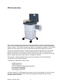
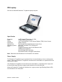
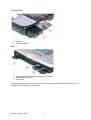
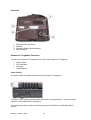
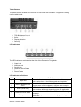
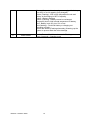
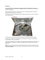
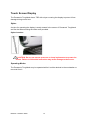
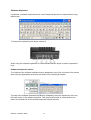
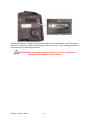
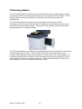
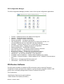
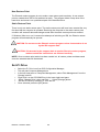
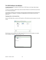
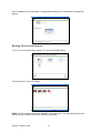
User Guide
Contents
Contents .................................................................................................................................................. 2
Acronyms and Abbreviations .................................................................................................................. 3
IDS Introduction ...................................................................................................................................... 4
IDS Laptop .............................................................................................................................................. 5
Power Supply ...................................................................................................................................... 5
Battery Charging.................................................................................................................................. 6
System Standby and Hibernation........................................................................................................ 6
Battery Calibration ............................................................................................................................... 7
Panasonic Toughbook Connections.................................................................................................... 8
Panasonic Toughbook Functions ...................................................................................................... 10
DVD Drive.......................................................................................................................................... 13
Touch Screen Display ........................................................................................................................... 14
Stylus ................................................................................................................................................. 14
Operating Modes ............................................................................................................................... 14
Calibrating the Touch Screen............................................................................................................ 16
Software Keyboard ............................................................................................................................ 17
Navigation.......................................................................................................................................... 18
Docking and Undocking ........................................................................................................................ 18
Vehicle Communication Module (VCM) ................................................................................................ 20
VCM Driver Software......................................................................................................................... 21
T4 Docking Station................................................................................................................................ 22
Using the USB Drive ............................................................................................................................. 24
PDF995 – Electronic Printing ................................................................................................................ 25
Main Menu ......................................................................................................................................... 26
GTR Marque Selection Screen ......................................................................................................... 26
GTR Selection Screen....................................................................................................................... 27
IDS Configuration Manager ............................................................................................................... 28
IDS Restore Software ........................................................................................................................... 28
Set Z:\ Drive .......................................................................................................................................... 29
T4 / IDS Software Installation ............................................................................................................... 30
Copying discs to the hard drive ......................................................................................................... 30
Running T4 from the hard drive......................................................................................................... 31
Contacting the Support Desk ................................................................................................................ 32
IDS Support Desk Contact Details .................................................................................................... 32
Trace Monitor .................................................................................................................................... 33
Car Configuration Files (CCF)............................................................................................................... 34
Going Mobile with IDS........................................................................................................................... 36
The information contained in this User Guide was correct at the time of printing.
NOTE: The IDS software is subject to continuous development. Therefore, deviations may
occur between the test procedures/scope of testing described in this user guide and IDS.
Release 1.0 March 2006
2
Acronyms and Abbreviations
The following acronyms and abbreviation have been used in this user guide:
CCF
CD
CDROM
CDRW
DDR
DLC
DTC
DVD
Gb
IDS
LAN
LED
Mb
OBD
RAM
SDRAM
TSD
USB
VCM
VMM
WDS
T4
LCS
Release 1.0 March 2006
Car Configuration File
Compact Disc
Compact Disc Read Only Memory
Compact Disc Rewritable
Double Data Rate
Diagnostic Link Connector
Diagnostic Trouble Code
Digital Versatile Disc
Giga Byte
Integrated Diagnostic System
Local Area Network
Light Emitting Diode
Mega Byte
On Board Diagnostics
Random Access Memory
Synchronous Data Random Access Memory
Touch Screen Display
Universal Serial Bus
Vehicle communication Module
Vehicle Measurement Module
Worldwide Diagnostic System
T4 Diagnostic System
Land Rover Coding System
3
IDS Introduction
IDS is a leap forward in diagnostic technology for Land Rover vehicles. IDS combines the
ease of use and familiarity of the previous T4/WDS software with an up to date specification
laptop computer. IDS is being introduced to improve the diagnostic capability of Land Rover
dealers and it will replace the current T4/WDS Dell laptop based diagnostic equipment.
IDS uses a standard Panasonic Toughbook laptop computer which has been specifically
designed to operate in an arduous environment and with the Vehicle Communications
Module (VCM) and T4 Docking Station offers diagnostics for past, current and future Land
Rover vehicles offering the same vehicles coverage as T4/WDS.
IDS includes a mobile workstation which provides the facility to store the Panasonic
Toughbook and associated hardware.
The diagnostic capabilities of IDS include:
• EOBD Diagnostics
• OBDII Diagnostics
• Full DTC Read and Datalogger Diagnostics
• Full Vehicle Configuration
• Full Vehicle Tune Update
• IDS Diagnostic Self Test
IDS uses existing T4 / WDS diagnostic principles, the look and operation of which are very
familiar to experienced technicians. IDS will be supplied pre loaded with the relevant
operating system software.
Release 1.0 March 2006
4
IDS Laptop
IDS uses a standard Panasonic Toughbook laptop computer.
Specification
Processor:
RAM:
Screen:
Hard Drive:
Optical Drive:
Operating system:
Other:
Intel® Centrino® Processor 1.2 GHz
512Mb DDR RAM minimum
10.4" Anti-Reflective Touch Screen Display (TSD) Colour Screen
60Gb minimum
External CD Writer/DVD Reader Combo-Drive
Microsoft® Windows® XP Professional
Bluetooth®
Integrated Wireless with 10/100 Ethernet LAN
56Kbps Internal Modem
Secure Digital (SD) Card Slot
Reversible Screen to Support Tablet Mode
Note: Bluetooth® and Wireless are not licensed in all markets.
Power Supply
The Panasonic Toughbook may be powered from its internal battery or from a mains power
supply. When the Panasonic Toughbook is docked on the workstation it is powered from the
mains power supply.
If the Panasonic Toughbook is removed from the workstation, a separate power supply can
be connected using the power supply socket located on the left hand side.
When the Panasonic Toughbook is switched on, a green power Light Emitting Diode (LED)
is illuminated on the front panel.
Release 1.0 March 2006
5
Internal Battery
The Panasonic Toughbook has its own internal lithium battery which is located on the right
hand side of the unit.
Battery Location
When the Panasonic Toughbook is powered from the internal battery, a battery symbol is
shown on the task bar. If the cursor is positioned on the battery symbol, the condition is
displayed together with the estimated operating time remaining.
Charging of the battery is automatically carried out when connected to the mains power
supply. The Panasonic Toughbook will operate for approximately four hours from a fully
charged battery in good condition.
NOTE: The power options and critical alarm actions have been set at the factory for
optimum performance and should not be changed.
Battery Charging
The battery life deteriorates each time it is charged. Charging the battery only when it has
become completely discharged will reduce the number of charge cycles and thus extend
battery life.
System Standby and Hibernation
System standby and hibernation will shut down the Panasonic Toughbook without closing
down programs or documents. Restarting the Panasonic Toughbook from standby or
hibernation mode will return to the same programs and documents that were open at the
time before the Panasonic Toughbook entered standby or hibernation.
Release 1.0 March 2006
6
When the Panasonic Toughbook enters standby mode, data is stored in memory (RAM) and
the recovery time is short. Power must be maintained in order to retain this data in the
memory. If power is lost, then the data will be lost.
When the Panasonic Toughbook enters hibernation mode, data is stored on the hard drive.
The recovery time is a little longer than when in standby mode. However, power is not
required in order to maintain the data.
Power Management Default Settings
Action
Running from mains power
supply
Running from internal
battery
Turn off monitor
Never
After 20 minutes
Turn off hard disc
After 1 hour
After 30 minutes
System standby
Never
Never
System hibernates
Never
Never
When power management has been activated the following must be completed to re-activate
the system.
Activating IDS Following Power Management Actions
Power Management Action
How to re-activate IDS
Monitor or Hard Disc is OFF
Touch the TSD or operate the enter key
System standby
Operate the power switch
System hibernation
Operate the power switch
Battery Power Display
The battery condition can be displayed by selecting "Fn +F9"
Battery Calibration
As the battery deteriorates the remaining battery capacity may not be displayed accurately.
In this situation, select the battery calibration function to recalibrate the battery. The battery
will be charged (if not already fully charged), then fully discharged.
Release 1.0 March 2006
7
During battery recalibration, the following actions are carried out:
•
•
•
•
Battery will be charged (providing it is not already fully charged)
Battery will be discharged
Computer will shut down
Battery will be charged
Panasonic Toughbook Connections
There are a number of connections on the Panasonic Toughbook to allow connection to
other devices.
Left Hand Side
1.
2.
3.
4.
5.
DC Power Supply Socket
USB Port
USB Port
Modem Connection Socket
Local Area Network (LAN) Connection Socket
6. SD Card Slot
SD Card Slot
Release 1.0 March 2006
8
Right Hand Side
1. Battery
2. Hard Disc Drive
Rear
1. Microphone and Headphone Socket Connections
2. External Display Port
3. Serial Port
The identification serial numbers, docking station connection and speaker are located on the
underside of the Panasonic Toughbook.
Release 1.0 March 2006
9
Underside
1.
2.
3.
4.
Replicator Port and Cover
Speaker
Operating System Serial Number
Serial Number
Panasonic Toughbook Functions
The following functions are located on the front of the Panasonic Toughbook:
•
•
•
•
Power Switch
LED Indicators
Lid Latch
Tablet Buttons
Power Switch
The power switch is located at the front of the Panasonic Toughbook.
To switch on IDS, slide the power switch and hold it for approximately 1 second, until the
indicator is illuminated before releasing it.
The laptop will power up and will automatically open the 'Welcome to IDS Main Menu'
screen.
Release 1.0 March 2006
10
Tablet Buttons
The tablet buttons located at the front are for use when the Panasonic Toughbook is being
used in tablet mode.
1. TSD Brightness Control
2. Software Keyboard
3. Enter
4. Display Rotation
5. Security
LED Indicators
The LED indicators are located at the front of the Panasonic Toughbook.
1.
2.
3.
4.
5.
6.
Caps Lock
Number Lock
Scroll Lock
Hard Disc Drive Status
Battery Status
Power Status
LED Indicator Definitions
LED
Function
1
Caps lock
2
NumLk (Number Lock
key)
3
ScrLk (Scroll lock)
4
Hard Disc Drive status
5
Battery status
Release 1.0 March 2006
Definition
Green - Indicates when caps lock is active. When caps
lock is active then all the letters typed are in capitals.
Green - Indicates when number key lock is active.
Causes some of the keyboard to perform as a numeric
keypad.
Green - Indicates when "Fn + ScrLk" are pressed. Scroll
lock functions differently depending upon the application
This illuminates to indicate when the hard drive is being
accessed
Not lit - Battery not connected or charging not being
carried out
11
Green - Connected to external power supply with battery
over 95% of its full capacity (fully charged)
Green (Flashing) - IDS in high temperature mode and
battery is discharging to 80% of capacity
Amber - Battery charging
Amber (Flashing) - Battery cannot be recharged
temporarily due to high internal temperature of battery
Red - Battery level very low, 9% or less
Red (flashing) - Fault with battery or charging not
operating correctly
Green and Amber (Flashing alternately) Warming up the
system to prevent hard disc drive damage
6
Power status
Release 1.0 March 2006
Not lit - Power off or Hibernation mode Flashing once
every 3 seconds – Standby mode
12
DVD Drive
An external DVD drive is used to install software updates. The DVD drive is connected
through a USB port to the Panasonic Toughbook and is located behind the front upper door
of the IDS workstation.
Before using the DVD drive for the first time, make sure all transit protection is removed
especially the cardboard cover inside the lid.
The DVD drive lid is opened by pressing the release catch located on the lid. The lid opens
under spring tension.
The DVD drive will automatically operate following a command from the IDS software.
IDS software is loaded onto the hard drive of the Panasonic Toughbook allowing IDS to
operate without a disc in the DVD drive.
A new feature of RDS 7.00 is the ability to copy the latest T4 Diagnostic CD to the hard drive
of the Panasonic Toughbook. This allows T4 Diagnostics to be run without a disc in the
DVD drive.
NOTE: Once the software has been loaded onto IDS, the disc should be removed from the
DVD drive and stored for future reference in the storage area located in the front upper door
of the IDS workstation.
Release 1.0 March 2006
13
Touch Screen Display
The Panasonic Toughbook has a TSD with a layer covering the display to protect it from
damage during normal use.
Stylus
A stylus for operating the display is neatly stowed in the screen of Panasonic Toughbook
and can be tethered using the tether cord provided.
Stylus Location
CAUTION: Do not use excess pressure or sharp implements to operate the
screen. Failure to follow this instruction may cause damage to the screen.
Operating Modes
The Panasonic Toughbook may be operated while it is either docked to the workstation or
removed from it.
Release 1.0 March 2006
14
Laptop Mode
When used with the display open, it is referred to as 'Laptop' mode as shown in the picture
below. When using laptop mode, the display may be tilted to any angle to suit the user.
Tablet Mode
The Panasonic Toughbook has the facility to reverse the display so that it is accessible in
the closed position. When used in this manner, it is referred to as 'tablet mode' as shown in
the picture below.
To use tablet mode, release the latch and open the display. Slide the release latch to the
right and rotate the display in a clockwise direction as shown in the illustration below.
Release 1.0 March 2006
15
Display Rotation Release Latch
Rotate the display 180° before closing it and then securing it in the closed position.
When changing to tablet mode, the image will re-orientate the display in the same orientation
as it was previously. This will prevent the image from appearing upside down. The
orientation of the image may also be changed using the tablet rotation button. Each press of
the tablet rotation button will rotate the image 180°.
Calibrating the Touch Screen
If the accuracy of the TSD display has depreciated then it may be recalibrated by selecting
the TSD configuration button. To access this menu, select 'IDS Configuration' from the
bottom right hand side of the main menu and then select 'Touch Screen Configuration'.
TSD Configuration Button
Release 1.0 March 2006
16
Software Keyboard
If preferred, a software keyboard can be used if keyboard operation is required when using
tablet mode.
To access the keyboard, press button number 2.
When using the software keyboard it is recommended that the stylus is used to operate the
keys.
Software Keyboard Location
The location of the software keyboard may be displayed in any of the 4 corners of the screen
area using the appropriate arrow keys as shown in the following illustration.
The size of the software keyboard may also be changed by using the square key at the top
left hand corner of the software keyboard. This will provide access to a drop down menu
where the desired size of the software keyboard may be selected.
Release 1.0 March 2006
17
Navigation
Navigating is normally achieved using the TSD, although a touch pad is located in the centre
of the Panasonic Toughbook. This is a pressure sensitive pad which may be used in the
same way as a conventional computer mouse.
Item
1
2
3
4
Description
Left mouse button
Right mouse button
Touch pad
TSD swivel release latch
Docking and Undocking
The Panasonic Toughbook should only be docked and undocked from the workstation whilst
switched off.
Undocking Procedure
To undock from the workstation, simply unlock the release latch using the key provided.
Operate the release latch and lift the Panasonic Toughbook clear of the workstation. The T4
Ethernet cable should be disconnected from the left side of the laptop.
All other connections will automatically be removed since connection to the workstation is
managed using a single connector.
Release 1.0 March 2006
18
Once the Panasonic Toughbook has been removed from the workstation, close the access
cover of the connector to prevent the ingress of dust and moisture. The docking procedure is
the reverse of the undocking procedure.
CAUTION: Make sure that the replicator port access cover is open before
attempting to dock IDS to the work station.
Release 1.0 March 2006
19
Vehicle Communication Module (VCM)
The VCM is a high performance, rugged, vehicle serial communications gateway. This
device provides vehicle communication interfaces between the vehicle and IDS for Land
Rover vehicles from LR3/Discovery 3 onwards.
The VCM unit is housed in a magnesium casing which also has a tough protective plastic
cover. The VCM is located behind the docking station under the lid of the IDS workstation. It
is attached to the bracket of the IDS workstation by locating lugs sliding into 'key holes' on
the bracket. The VCM is easily removed from the bracket when required.
The VCM has 3 sockets for external connections, 2 of the sockets are used to connect to
IDS and to the vehicle. The 3rd socket is used for a 12V DC power supply, but this is not
used on this application. The VCM is powered up via the DLC when it is connected to the
vehicles diagnostic socket. Once the VCM is ready for use a symbol will appear in the
bottom right hand corner of the screen. Do not proceed until the symbol has appeared, this
may take up to several minutes before the symbol appears.
The VCM features 5 LED’s which are used to indicate status. The 5 LED indicators are
visible through the plastic cover of the VCM. Details of the LED’s are given below:
LED
Colour
Purpose
1
Amber
Vehicle link
2
Green
VCM operating
3
Red
4
Green
5
Amber
Release 1.0 March 2006
Normal Status
Flashes when communicating to
the vehicle
Lit when in normal mode
Power supply
Lit when in normal mode
Flash memory
access
Should be OFF in normal mode
Host Link
20
Flashes when communicating to
the Panasonic Toughbook
VCM Driver Software
In order to use the VCM it is necessary to download the latest driver software. Each time that
the VCM is connected to IDS and the VCM is powered up, the stored driver software version
will be checked. If later driver software is available, a message will be displayed and the
VCM will be updated.
Once the software has been downloaded to the VCM, diagnostics with the vehicle may be
carried out as normal.
CAUTION: Do not switch off IDS or disconnect the VCM during a software
download. Failure to follow this instruction may cause damage to the VCM or may
cause communication errors when attempting to diagnose vehicle faults.
Release 1.0 March 2006
21
T4 Docking Station
The T4 Docking Station is required in order to allow IDS to carry out diagnostics to Legacy
Land Rover products from Range Rover Classic to New Range Rover up to 05MY. The T4
Docking Station is the main interface for both vehicle communications and for T4
measurement.
The T4 Docking Station is located in the second drawer on the side of the IDS
Workstation, and connected to the Panasonic Toughbook using an Ethernet cable routed
around the base of the docking station. The drawer has an opening to allow connection of
the test leads to the T4 Docking Station.
The T4 Docking Station also supports the upload and download of information to the optional
T4 Hand Held Tester (T4 HHT). The T4 Hand Held Tester is powered directly from a
vehicle's J1962 Diagnostic Socket and operates as a stand alone unit to provide Scan Tool
functionality and can also be used for basic configuration/programming, reading DTCs and
viewing Real Time Data on Land Rover vehicles. Data can be stored to the T4 HHT and
then uploaded to the T4 to enable the data to be printed.
Release 1.0 March 2006
22
IDS Workstation
The IDS workstation has been purpose designed and provides a secure and safe storage
facility for the Panasonic Toughbook and associated IDS hardware. It also allows charging
from a mains power supply.
The replicator port is located beneath the lid of the workstation and provides a secure
mounting point for the Panasonic Toughbook. The VCM is stored behind the replicator port
providing visibility of the status LED’s whilst in use.
The front drawers and lower compartments allow for storage of cables and test lead
adaptors. The inside of the front upper door also provides storage for release notes, job
cards and the IDS software discs. Access to the external DVD drive is also available.
The top drawer on the side of the workstation provides the facility to hold 2 standard sized
drinking cups and a compartment for storing documents. When the drawer is open it
provides a surface for documents, such as job cards or circuit diagrams.
The workstation is easily moved on the 4 castors. The 2 front castors have a brake facility to
prevent the workstation from moving.
The base of the workstation has a tether point to secure it to a suitable anchor point in the
workshop.
Release 1.0 March 2006
23
Using the USB Drive
A USB drive is supplied to allow files to be stored or transferred to another computer.
To use the USB drive, insert it into one of the USB ports. After a short time, the USB drive
will be recognized and the software will open and display the contents of the drive. A symbol
will appear on the task bar to indicate that a USB device is connected.
CAUTION: Do not remove the USB drive from IDS without first closing the drive
and carrying out the disconnection procedure.
Before removing the USB drive select the USB symbol on the task bar. The following
message will be displayed: 'Safely remove USB mass storage device'. Select the
message. A confirmation message will be displayed stating that it is safe to remove the USB
drive and the symbol will disappear from the task bar.
Release 1.0 March 2006
24
PDF995 – Electronic Printing
PDF995 is a program which will allows the user to capture screen images and save them as
a portable document format (PDF) file. These files may then be saved to a preferred file
destination of the computer, or the USB drive and transferred to another computer for
printing or e-mailing etc.
When a problem exists it is extremely helpful if the screen images are captured and sent to
the support desk. To capture the screen image, select the 'Select System Options' button.
When the 'Print screen' confirmation message is displayed, select the tick symbol.
A 'Pdf995 Save As' window will be displayed. Select the address where the file is to be
saved and give the file a name.
For Example: Save in: My Documents, IDS screen images. File name: VIN_012345_ DTC1
Select save. Adobe Reader will be opened displaying an image of the screen you have
captured. Close the document. To locate the document, open the desktop and go to the file
where the document has been saved.
PDF995 should be used with the USB drive to allow quick and easy printing of diagnostic
screen shots, vehicle reports etc.
Release 1.0 March 2006
25
IDS Software
Main Menu
The 'Welcome to IDS Main Menu' screen will automatically be displayed once IDS has been
switched on.
The following options may be selected from the 'Welcome to IDS Main Menu' screen:
•
•
•
•
•
•
T4 – this launches the T4 Diagnostic System
IDS – this launches the IDS applications
GTR – this launches the GTR selection screen (see below)
CD Install – this launches the T4 CD Install utility.
Support – this displays the IDS support contact numbers
IDS Configuration – this launches the IDS Configuration Manager
GTR Marque Selection Screen
Use this screen to select vehicle brand.
Release 1.0 March 2006
26
GTR Selection Screen
The following explains each button:
GTR Dealer Extranet is being progressively replaced by Dealer Portal. The
Dealer Extranet is a web page to allow users to login once and access several
business applications from a single source.
GTR Dealer Portal is currently being rolled out globally. Dealer Portal is a
web page to allow users to login once and access several business
applications from a single source.
GTR Public Internet is the link to be used for access to GTR mainly by
Independent Repairers.
Internal - This is for internal Land Rover employees to access GTR via the
Intranet.
Release 1.0 March 2006
27
IDS Configuration Manager
The IDS Configuration Manager provides a menu of set-up and configuration applications.
•
•
•
•
•
•
•
•
•
•
•
•
•
•
•
•
•
Printers – Enables printers to be added and configured.
Internet – Configure internet connections
Network – Configure network connections
Phone and Modem – Configures the Modem
Disk Defragmenter – Runs disk defragmenter to improve file access, it is
recommended that this is run after each new disk installation
Scandisk – Inspects hard disc drive for unused files and removes them
PC information viewer – Displays current PC configuration
Battery recalibration – Recalibrates the battery
Intel PROSet wireless – Configures wireless network connection
Bluetooth settings – Configures Bluetooth connections
Bluetooth file transfer – Transfer files using Bluetooth network
Touchscreen / Touchpad – Reconfigures the touch screen
IDS Monitor – this launches the Monitor Trace application
T4 Mobile+ Driver Installation – Installs software updates to the Laptop
T4 Mobile+ Firmware Updates – Installs updates for the T4 Mobile+ communications
box
Set Z:\ Drive – Changes the DVD drive letter to Z
IDS Restore – Runs the IDS restore software
IDS Restore Software
The IDS restore software is installed on IDS and may be used to reset the Panasonic
Toughbook to known good previous condition or rest to the factory supplied condition. IDS
restore uses a software package called 'Phoenix FirstWare Recover Pro'.
The 2 options are:
• New Restore Point (known good condition)
• Static Restore Point (factory condition)
Release 1.0 March 2006
28
New Restore Point
The Phoenix restore program is set to make a new restore point each day. A new restore
point is created when IDS is first switched on daily. The program takes a snap shot of the
hard drive and stores it on a partitioned part of the hard disc drive.
Static Restore Point
There is only one static restore point. The static restore point will have been created the very
first time that the computer is operated. Restoring the computer to the static restore point
condition will erase all data and changes made after the static restore point was created.
If 'Windows' fails to run on 6 consecutive attempts of switching on IDS, the Phoenix restore
program will automatically be opened.
CAUTION: Do not access the Phoenix restore program unless instructed to do so
by the IDS support desk.
CAUTION: If instructed by the support desk to use the Phoenix restore program,
make sure that the instructions are followed carefully.
NOTE: Once a restore point action has been carried out, all restore points and data saved
since the selected date will be deleted.
Set Z:\ Drive
•
•
•
•
•
•
•
Select the Z:\ Drive icon from IDS Configuration Manager,
This will start Computer Management.
In the left hand pane of Computer Management, select ‘Disk Management’ from the
‘Storage’ section.
‘Right Click’ on the CD-ROM Drive in the lower right hand pane.
Select ‘Change Drive Letter and Path…’. Select [Change] button.
Set the CD Drive by selecting ‘Z’ from the list.
Once selected, press the [OK] button.
Release 1.0 March 2006
29
T4 / IDS Software Installation
The IDS software will be released in DVD format. A DVD has a much larger data storage
capacity than a CD.
To carry out a software update simply insert the latest IDS disc into the DVD drive and follow
the on screen instructions.
A new feature of RDS 7.00 is the ability to copy the latest T4 Diagnostic CD to the hard drive
of the Panasonic Toughbook. This allows T4 Diagnostics to be run without a disc in the
DVD drive.
Copying discs to the hard drive
From the IDS Main Menu, select the CD Install icon. IDS will then scan the system for a valid
image.
IDS will then scan the system for a valid image. Select the source of the data to be copied,
CD or USB drive, and then select the Green ‘Tick’.
Release 1.0 March 2006
30
Once Installation to the hard disc is completed successfully, a confirmation message will
appear
.
Running T4 from the hard drive
To run T4 from the hard drive select “T4” from the IDS Main Menu.
Then select the correct CD image.
NOTE: Only the latest CDs can be installed to the hard drive, if an older disc needs to be
used, then this can be run from the CD drive as normal.
Release 1.0 March 2006
31
Contacting the Support Desk
In the event that problems are experienced using IDS and they cannot be resolved by
repeating the procedure or by consulting IDS literature, contact the IDS Support Desk for
assistance.
IDS Support Desk Contact Details
Region
Phone Number
Web Address
Europe/ROW
00800 77977910
www.spxtools.com
ROW
+49 (0) 6182 959400
www.spxtools.com
USA
+1 (1) 800 5335338
www.spxtools.com
Japan
+81 (0) 45 5624483
www.spxtools.com
Mexico
+52 (01) 55 25951630
www.spxtools.com
The IDS Support Desk will carry out a call qualification check.
NOTE: IDS support is carried out by SPX and not the Dealer Technical Support Hotline.
Dealer Technical Support Hotline will ONLY deal with vehicle concerns.
Before contacting the IDS Support Desk make the following details are available:
•
•
•
•
•
•
•
•
•
•
•
Dealer Name
Dealer code
Telephone Number
Fax Number
Contact name
IDS Serial/Model Number
VIN of the vehicle being tested
Details of the test being carried out
Details and description of the fault
Details of any error messages displayed
The IDS software application details. Example: IDS DVD 100 v5
Vehicle Details and Reported Fault
This should include the exact vehicle model, derivative, model year and VIN, plus any
component numbers or codes relevant to the area of the vehicle being worked on. When
combined with details of the reported fault that is being diagnosed, this gives the IDS
engineers a short cut to a solution based on previous experience.
Details of Test Being Carried Out
This information is vital to an IDS engineer who is trying to reproduce and solve the problem.
Some diagnostics may be reached using several different routes. It is vital that the IDS
engineers follow exactly the same diagnostic route as the technician experiencing the
problem. It would help if a note of each screen where a decision is made so the IDS
engineer can follow exactly the same route.
Release 1.0 March 2006
32
For Example:
• Select 'Diagnostic System'
• Select 'Security'
• Select 'Locking/Unlocking'
• Select 'Guided Diagnostics'
Continue the route until the screen is reached where the fault occurred.
Full Details of Any Difficulties Using IDS
It may be useful to IDS engineers if they are informed of difficulties experienced when using
IDS even though you may have resolved the problem yourself. This information may then be
used to prevent problems occurring in the future.
NOTE: If the IDS screen on which the problem occurred is one of those that can be printed,
please print it off and fax it through to the IDS Support Desk with the Information Sheet. The
more information provided to the IDS Support Desk, the faster they can resolve the problem.
Trace Monitor
Trace Monitor creates a file containing all details of a diagnostic routine carried out. For
some problems a trace monitor may be requested by the IDS support engineer. Trace
Monitor can be run from the IDS Configuration screen.
Release 1.0 March 2006
33
Car Configuration Files (CCF)
CAUTION: Vehicle low battery conditions will adversely affect module
programming and CCF uploading or downloading, and may damage the vehicle. When
any programming functions are being performed the vehicle must be connected to a
suitable battery charger and the Panasonic Toughbook is fully charged.
The CCF on the vehicle replaces what was previously known as the Land Rover Coding
System, LCS. Although LCS data, has been replaced by CCF data the principles of the two
are similar.
The CCF consists of 2 parts:
• Vehicle Parameters
• Vehicle Module Codes
Vehicle parameters are derived from the vehicle specification and relate to which features
are fitted to the vehicle and their market settings. This is sent round on the CAN network to
be used by the modules on the vehicle. Vehicle module codes are the data used in
manufacturing to specify the vehicle and are stored to be used in service.
The CCF is stored in various modules around the car. The data is stored in the "Master"
control module and also in a number of "Back-up" control modules.
The master control module transmits the vehicle parameters section of the CCF on the CAN
bus. When ever the CAN network is active, the master control module broadcasts the CCF
onto the network at regular intervals.
The back-up control modules contain backup copies of this data and do not broadcast the
CCF onto the network. IDS is the only way of updating the back-up copies of the CCF data.
The car does not update the back-up copies.
The master control module will monitor the integrity of the CCF data and if a fault is detected
a DTC will be set. Within the vehicle parameters section the vehicle VIN is stored. The VIN
data is implanted and locked into every module that is capable of accepting it, during the
programming process. This has service implications as it is a vehicle security feature and will
prevent the swapping of modules from vehicle to vehicle.
Examples of data held in the vehicle parameters section are:
• Vehicle Type
• Brand
• Model Year
• VIN
• Tyre Dynamic Rolling Radius
• Brake System Type
• Brake Disc size
• Final Drive Ratio
• Transmission Type
• Hand of Drive
• MOST configurations
Some of the CCF vehicle parameters can be altered by the customer as part of the
personalization mode. Some of these parameters may be able to be changed by the driver.
Release 1.0 March 2006
34
Changing the personalization settings changes the master CCF but does not update the
back-up copies.
IDS may be used to configure new and existing modules and also to change personalization
settings. There will also be a CCF editing tool built into IDS which will allow certain
parameters of the CCF to be changed. Whenever IDS is used to change the CCF file, the
other modules will also be programmed with the CCF data as part of the process. This
makes sure that all modules which hold the CCF data all contain the same information.
Replacing a module which contains the CCF data is possible because IDS can retrieve the
data from one of the other modules and then download it to the new module. If for some
reason the CCF data in the other modules has been wiped from the modules or has been
overwritten using incorrect data, then it will also be possible to retrieve the 'as built' CCF
data from the IDS software disc.
This CCF data will be the same as was originally programmed to the vehicle during
manufacture. If any accessories have since been fitted to the vehicle in Service which
required the CCF data to be modified, then the CCF will then need to be modified to allow
these accessories to operate. The vehicle module codes held in the master and back-up
modules will also be read by IDS when requested. These vehicle module codes are not
transmitted on the CAN bus and are only read by IDS.
Accessing CCF Data using IDS
When carrying out diagnostics using IDS, the CCF data must first be uploaded in order for it
to be viewed. Select the upload, view and modify from the menu. IDS will then communicate
with the vehicle and the CCF data will then be displayed. Certain parameters of the CCF file
will have the option of allowing the user to modify it. This option will only be available when it
is necessary.
Example, the fitting of an accessory may need the CCF to be changed in order for the
accessory to operate.
Release 1.0 March 2006
35
Going Mobile with IDS
To “Go Mobile” with the IDS the Panasonic Toughbook should undocked from the
workstation whilst switched off.
Undocking Procedure
The T4 Ethernet cable should be disconnected from the left side of the laptop. To undock
from the workstation, simply unlock the release latch using the key provided. Operate the
release latch and lift the Panasonic Toughbook clear of the workstation.
All other connections will automatically be removed since connection to the workstation is
managed using a single connector.
VCM Removal
The VCM should also be removed whilst the Panasonic Toughbook and vehicle are turned
off. It is removed by lifting it off the four keyholes that secure it to the trolley via lugs on the
VCM and disconnecting the USB cable from the Panasonic Docking Station. The VCM can
be removed from the trolley with the DLC cable and USB cables still attached.
Once in the vehicle to be tested the VCM USB cable
can be fitted to one of the USB ports on the left of
the Laptop.
IDS is now ready to go mobile.
Release 1.0 March 2006
36