1
Date
: 26 January 2007
Doc. no. : DCAM_Camera_DevKit_UG
Iss./Rev : 1.00
Page
:1
User’s Guide
DCAM Camera Development Kit
(using the UC1394a-3 MCM)
Orsys Orth System GmbH, Am Stadtgraben 25, 88677 Markdorf, Germany
http://www.orsys.de
USER’S GUIDE
DCAM CAMERA DEVELOPMENT KIT
Date
: 26 January 2007
Doc. no. : DCAM_Camera_DevKit_UG
Iss./Rev : 1.00
Page
:2
Contents
1 PREFACE...................................................................................................................... 7
1.1
Document Organization ......................................................................................................... 7
1.2
Documentation Overview ...................................................................................................... 7
1.3
Notational conventions.......................................................................................................... 7
1.4
Trademarks ............................................................................................................................. 9
1.5
Revision history ..................................................................................................................... 9
2 KIT OVERVIEW ........................................................................................................... 10
2.1
UC1394a-3 MCM ................................................................................................................... 10
2.2
Camera BSP and DCAM Camera API ................................................................................. 11
2.3
Ultra-Compact Small Carrier ............................................................................................... 11
2.4 Interfaces and Connectors .................................................................................................. 11
2.4.1 Camera Interface................................................................................................................. 12
2.4.2 IEEE1394 Interface ............................................................................................................. 13
2.4.3 UART Interface.................................................................................................................... 13
2.4.4 8-bit HPI or General-purpose I/O ........................................................................................ 13
2.4.5 McBSP Interfaces................................................................................................................ 14
2.4.6 I2C Interface......................................................................................................................... 14
2.4.7 Timer Signals ...................................................................................................................... 14
2.4.8 XF Output ............................................................................................................................ 14
2.4.9 LED ..................................................................................................................................... 14
2.5
JTAG Connector................................................................................................................... 14
2.6
Power Supply Input .............................................................................................................. 15
3 GETTING STARTED ................................................................................................... 16
4 PROGRAMMING THE UC1394A-3 ............................................................................. 18
4.1
Required Items ..................................................................................................................... 18
4.2
Software Development Flow ............................................................................................... 18
4.3 Running an Application with Code Composer Studio ...................................................... 19
4.3.1 Debugging of the Software .................................................................................................. 20
4.4
Programming an Application into Flash Memory.............................................................. 21
4.5
Startup Procedure ................................................................................................................ 21
4.6
Hints for Programming the TMS320VC5501/5502 ............................................................. 22
USER’S GUIDE
DCAM CAMERA DEVELOPMENT KIT
4.6.1
4.6.2
4.6.3
Date
: 26 January 2007
Doc. no. : DCAM_Camera_DevKit_UG
Iss./Rev : 1.00
Page
:3
A Byte is 16 Bits .................................................................................................................. 22
64K Page Limit .................................................................................................................... 22
Pipeline................................................................................................................................ 22
5 APPLICATION EXAMPLES ........................................................................................ 24
5.1
LED Control (toggle_led) ..................................................................................................... 25
5.2
UART (hello).......................................................................................................................... 25
5.3
Buffered Character I/O (dbg_out) ....................................................................................... 25
5.4
MCM Information Utility (mcm_info)................................................................................... 26
5.5
Image Source Information Utility (sensor_check)............................................................. 26
5.6
DCAM Application Examples .............................................................................................. 27
6 MODULE SUPPORT LIBRARY .................................................................................. 28
6.1 Module Support Library Modules ....................................................................................... 28
6.1.1 init.c ..................................................................................................................................... 28
6.1.2 fpgaload.c............................................................................................................................ 28
6.1.3 uart.c ................................................................................................................................... 28
6.1.4 flash.c .................................................................................................................................. 28
6.1.5 debug.c................................................................................................................................ 28
6.1.6 hexutil.c ............................................................................................................................... 28
6.1.7 decutil.c ............................................................................................................................... 28
6.2
Module Support Library Header Files ................................................................................ 29
6.3 Global Variables Reference................................................................................................. 29
6.3.1 Clock Rates ......................................................................................................................... 29
6.3.2 Interrupt Vector Table.......................................................................................................... 29
6.4 Macros Reference ................................................................................................................ 29
6.4.1 DebugOutByteHex .............................................................................................................. 29
6.4.2 DebugOutConstString ......................................................................................................... 30
6.4.3 DebugOutDwordHex ........................................................................................................... 30
6.4.4 DebugOutNibbleHex ........................................................................................................... 30
6.4.5 DebugOutSByteDec ............................................................................................................ 31
6.4.6 DebugOutSDwordDec ......................................................................................................... 31
6.4.7 DebugOutSNibbleDec ......................................................................................................... 31
6.4.8 DebugOutString................................................................................................................... 31
6.4.9 DebugOutSWordDec........................................................................................................... 32
6.4.10 DebugOutUByteDec.......................................................................................................... 32
6.4.11 DebugOutUDwordDec....................................................................................................... 32
6.4.12 DebugOutUNibbleDec....................................................................................................... 33
6.4.13 DebugOutUWordDec ........................................................................................................ 33
6.4.14 DebugOutWordHex ........................................................................................................... 33
6.4.15 UC1394A3_LED_ON ........................................................................................................ 34
6.4.16 UC1394A3_LED_OFF....................................................................................................... 34
6.4.17 UC1394A3_LED_TOGGLE............................................................................................... 34
USER’S GUIDE
DCAM CAMERA DEVELOPMENT KIT
Date
: 26 January 2007
Doc. no. : DCAM_Camera_DevKit_UG
Iss./Rev : 1.00
Page
:4
6.5 Functions Reference............................................................................................................ 34
6.5.1 InitDSP ................................................................................................................................ 34
6.5.2 IntHook ................................................................................................................................ 34
6.5.3 IntEnable ............................................................................................................................. 34
6.5.4 IntDisable ............................................................................................................................ 35
6.5.5 IntClear................................................................................................................................ 35
6.5.6 FpgaLoad ............................................................................................................................ 35
6.5.7 FlashGetDeviceInfo............................................................................................................. 36
6.5.8 FlashEraseSector................................................................................................................ 36
6.5.9 FlashProgram ...................................................................................................................... 37
6.5.10 DebugBufmgr .................................................................................................................... 37
6.5.11 DebugFlush ....................................................................................................................... 38
6.5.12 DebugGetc ........................................................................................................................ 38
6.5.13 DebugGets ........................................................................................................................ 39
6.5.14 DebugInit ........................................................................................................................... 39
6.5.15 DebugKbhit........................................................................................................................ 39
6.5.16 DebugPutc......................................................................................................................... 39
6.5.17 DebugPuts......................................................................................................................... 40
6.5.18 DecSignedByte2Ascii ........................................................................................................ 40
6.5.19 DecSignedDword2Ascii..................................................................................................... 40
6.5.20 DecSignedNibble2Ascii ..................................................................................................... 41
6.5.21 DecSignedWord2Ascii....................................................................................................... 41
6.5.22 DecUnsignedByte2Ascii .................................................................................................... 41
6.5.23 DecUnsignedDword2Ascii................................................................................................. 42
6.5.24 DecUnsignedNibble2Ascii ................................................................................................. 42
6.5.25 DecUnsignedWord2Ascii................................................................................................... 42
6.5.26 HexByte2Ascii ................................................................................................................... 43
6.5.27 HexDword2Ascii ................................................................................................................ 43
6.5.28 HexNibble2Ascii ................................................................................................................ 43
6.5.29 HexWord2Ascii.................................................................................................................. 44
6.5.30 UartClearRts...................................................................................................................... 45
6.5.31 UartClearToSend .............................................................................................................. 45
6.5.32 UartDisableLinestatInt ....................................................................................................... 45
6.5.33 UartDisableRxInt ............................................................................................................... 45
6.5.34 UartDisableTxInt................................................................................................................ 46
6.5.35 UartEnableLinestatInt........................................................................................................ 46
6.5.36 UartEnableRxInt ................................................................................................................ 47
6.5.37 UartEnableTxInt ................................................................................................................ 47
6.5.38 UartInit............................................................................................................................... 47
6.5.39 UartLinestatIntStat............................................................................................................. 47
6.5.40 UartLineStatus................................................................................................................... 48
6.5.41 UartReceive....................................................................................................................... 48
6.5.42 UartRxIntStat..................................................................................................................... 48
6.5.43 UartRxReady..................................................................................................................... 49
6.5.44 UartSetRts......................................................................................................................... 49
6.5.45 UartShutdown.................................................................................................................... 49
6.5.46 UartTransmit...................................................................................................................... 49
6.5.47 UartTxDone ....................................................................................................................... 50
6.5.48 UartTxIntStat ..................................................................................................................... 50
6.5.49 UartTxReady ..................................................................................................................... 50
7 FPGA DEVELOPMENT SUPPORT............................................................................. 52
8 LIST OF ABBREVIATIONS USED IN THIS DOCUMENT .......................................... 53
USER’S GUIDE
DCAM CAMERA DEVELOPMENT KIT
Date
: 26 January 2007
Doc. no. : DCAM_Camera_DevKit_UG
Iss./Rev : 1.00
Page
:5
9 LITERATURE REFERENCES..................................................................................... 54
USER’S GUIDE
DCAM CAMERA DEVELOPMENT KIT
Date
: 26 January 2007
Doc. no. : DCAM_Camera_DevKit_UG
Iss./Rev : 1.00
Page
:6
List of Tables
Table 1: UART connector pin assignments..................................................................................... 13
List of Figures
Figure 1: DCAM Camera Development Kit block diagram .............................................................. 10
Figure 2: DCAM camera overview .................................................................................................. 12
Figure 3: Ulrta-cmpact small carrier board connector locations ...................................................... 11
Figure 4: UART interface block diagram ......................................................................................... 13
Figure 5: JTAG Adapter .................................................................................................................. 14
Figure 6: Software development flow .............................................................................................. 19
Figure 7: Memory view of a string in character format .................................................................... 22
Figure 8: Memory view of a string in binary format ......................................................................... 22
Figure 9: Sample session of the hello example............................................................................... 25
USER’S GUIDE
DCAM CAMERA DEVELOPMENT KIT
Date
: 26 January 2007
Doc. no. : DCAM_Camera_DevKit_UG
Iss./Rev : 1.00
Page
:7
1 Preface
This document describes the DCAM Camera Development Kit when implemented on the
UC1394a-3 multi-chip-module (MCM). The DCAM Camera Development Kit allows to build an
IIDC1394 compliant camera using a low-level digital image source. The DCAM Camera
Development Kit consists of the UC1394a-3 MCM mounted on a carrier board , an FPGA design
that transforms the parallel input data to IEEE1394 isochronous data packets and the DCAM
camera API that implements the IIDC 1394-based Digital Camera Specification V1.30.
1.1
Document Organization
This document is organized as follows:
• Chapter 2 gives a brief overview of the whole system and its interfaces
• Chapter 3 shows how to do the first steps with the kit
• Chapter 4 gives an introduction to software development
• Chapter 5 describes the application examples
• Chapter 6 documents the module support library
• Chapter 7 introduces the FPGA development option
• Chapter 8 explains the abbreviations that are used throughout this document
• Chapter 9 lists documents that contain further information
1.2
Documentation Overview
This chapter lists the documentation from Orsys that is shipped together with the DCAM Camera
Development Kit. Further documents from other vendors are listed in chapter 9 and are referenced
throughout the document in square brackets.
UC1394a-3 Hardware Reference Guide [15] (UC1394a-3_hrg.pdf):
Describes the hardware of the UC1394a-3 MCM. It is intended to get an overview of the MCM and
the basic features provided by it. This manual is the recommended starting point for hardware
developers.
Camera BSP User's Guide [16] (DSP_Camera_BSP_UG.pdf):
Describes the DSP Camera Board Support Package (BSP). This BSP adds an 8-/16-bit interface
for image data to the UC1394a-3 MCM, including two FIFO buffered data paths and geometry
detection.
DCAM Camera API User's Guide [17] (DCAM_Camera_API_ug.pdf):
Describes the DCAM application programmer’s interface (API) that is used to implement the
IIDC1394-based digital camera protocol and to control the connected camera / image sensor.
Ultra-compact Small Carrier Hardware Reference Guide [18] (uc_sc_hrg.pdf):
Describes the carrier board that is used with the DCAM Camera Development Kit, including
schematics and hints for power supply configuration.
1.3
Notational conventions
Names of registers, bit fields and single bits are written in capital letters.
Example: LLC_VERSION
Names of signals are also given in capital letters, active low signals are marked with a '/' at the
beginning of the name.
Example: /RESETIN
Configuration parameters, function names, path names and file names are written in italic typeface.
Example: dev_id
USER’S GUIDE
DCAM CAMERA DEVELOPMENT KIT
Date
: 26 January 2007
Doc. no. : DCAM_Camera_DevKit_UG
Iss./Rev : 1.00
Page
:8
Source code examples are given in a small, fixed-width typeface.
Example: int a = 10;
Menus and commands from menus and submenus are enclosed in double-quotes. Example:
Create a new project using the "Create Project..." command from the "File" menu.
The members of a bit field or a group of signals are numbered starting at zero, which is the least
significant bit.
Example: CFG[4:0] identifies a group of five signals, where CFG0 is the least significant bit and
CFG4 is the most significant bit.
If necessary, numbers are represented with a suffix that specifies their base.
Example: 12AB16 is a hexadecimal number (base 16 = hexadecimal) and is equal to 477910.
The bit fields of a register are displayed with the most significant bit to the left. Below each bit field
is a description of its read / write accessibility and its default value:
bit number
bit name
15
14
13
12
11
10
6
5
4
3
2
1
0
A
B
C
D
E
F
9
G
8
7
H
I
J
K
L
N
O
r,w,0
r,w,0
r,w,0
r,w,0
r,w,0
r,w,0
r,w,0102
r,0
r,wc,0
w
r,w,0
rc,0
r,w,0
r,w,0
accessibility and default value
legend:
r
bit is readable
rc
this bit is cleared after a read
r,w bit is readable and writeable, reading yields the previously written value unless otherwise
specified.
w
bit is writeable, read value is undefined
wc writing a '1' to this bit clears it
w,0 bit is write-only, reading always yields 0.
0
default value
USER’S GUIDE
DCAM CAMERA DEVELOPMENT KIT
1.4
Date
: 26 January 2007
Doc. no. : DCAM_Camera_DevKit_UG
Iss./Rev : 1.00
Page
:9
Trademarks
TI, Code Composer, DSP/BIOS and TMS320C5000 are registered trademarks
of Texas Instruments.
Microsoft® and Windows® are either registered trademarks or
trademarks of Microsoft Corporation in the United States and/or other
countries.
Hypterterminal is a trademark of Hilgraeve Inc.
All other brand or product names are trademarks or registered trademarks of
their respective companies or organizations.
1.5
Revision history
Revision
1.0
Changes
First release
USER’S GUIDE
DCAM CAMERA DEVELOPMENT KIT
Date
: 26 January 2007
Doc. no. : DCAM_Camera_DevKit_UG
Iss./Rev : 1.00
Page
: 10
2 Kit Overview
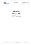
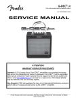
The hardware of the DCAM Camera Development Kit consists of a UC1394a-3 MCM mounted on
a carrier PCB. Figure 1 shows a block diagram of the whole system.
Figure 1: DCAM Camera Development Kit block diagram
2.1
UC1394a-3 MCM
The UC1394a-3 MCM is the main part of DCAM Camera Development Kit. It provides all
necessary functions except needed to build an IIDC-compliant camera. After development is
finished, the UC1394a-3 can be easily integrated into a customized hardware environment. Its
small size and low cost makes it an ideal solution for end-product usage. Further, the
USER’S GUIDE
DCAM CAMERA DEVELOPMENT KIT
Date
: 26 January 2007
Doc. no. : DCAM_Camera_DevKit_UG
Iss./Rev : 1.00
Page
: 11
implementation as a multi chip module (MCM) allows similar handling as of integrated circuits,
therefore mass production is supported.
2.2
Ultra-Compact Small Carrier
The Ultra Compact small carrier provides all necessary connectors and control elements:
•
•
•
•
•
•
•
•
Two 400 Mbps IEEE1394 ports with standard 6 pin connectors.
Connectors that provide direct access to each MCM signal
Power supply either from an external source or over the IEEE1394 cable
A red LED as power indicator
A reset button
A JTAG connector for access to the DSP’s and FPGA’s JTAG interfaces
RS-232 level converter and RS-232 connector that provides the UART interface with RS232 voltage levels
A jumper block (not used by the Camera BSP)
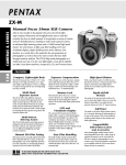
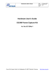
The carrier board is intended as a development aid, which is used in the prototyping stage of a
project. In the end product, the UC1394a-3 MCM will typically be used standalone. However, the
complete kit (MCM mounted on carrier) is also available in quantities. A detailed description of the
carrier hardware, including schematics and component lists can be found in [18].
Jumper JTAG
DC
block
connec tor input
UC1394a-3
MCM
Direc t MCM
connec tors
+
Reset
Power
indic ator LED
IEEE1394
connec tors
RS-232
connec tor
Figure 2: Ulrta-cmpact small carrier board connector locations
2.3
Camera BSP and DCAM Camera API
The DSP camera board support package (BSP) adds a camera interface (8 / 16-bit image data,
pixel clock, frame- & line-enable) to the MCM. The camera interface is used to connect a digital
camera or image sensor to the MCM. The camera BSP is described in [16]. The camera interface
USER’S GUIDE
DCAM CAMERA DEVELOPMENT KIT
Date
: 26 January 2007
Doc. no. : DCAM_Camera_DevKit_UG
Iss./Rev : 1.00
Page
: 12
and the connected camera / image sensor are controlled by the DCAM camera API, which is
described in [17]. Devices connected to the IEEE1394 bus that support the host side DCAM
protocol recognize the MCM with the camera / image sensor as a fully IIDC1394 compliant digital
camera. The camera interface is set up and controlled by he DCAM camera API, which is
described in [17]. The DCAM camera API also provides the necessary infrastructure for image
sensor control: Incoming camera control commands from a host trigger callback functions, where
individual sensor control can be implemented.
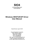
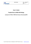
Figure 3: DCAM camera overview
The DSP on-chip interfaces listed below can be used to control the camera / image sensor. These
interfaces are described in [15].
• UART interface
• 8-bit HPI or up to 16 general-purpose digital IO
• 2 McBSP interfaces
• I2C interface
• 2 timer inputs/outputs
• XF output
Additionally, the FPGA can also be used for sensor control as described in chapter 7.
2.4
Interfaces and Connectors
2.4.1 Camera Interface
The camera interface is the main interface of the DCAM Camera Development Kit. It allows high
speed data transfers of up to 32,768,000 bytes per second. The camera interface is a configurable
8 / 16-bit parallel port that receives pixel clock, line and frame synchronization from the connected
camera / image sensor. The incoming image data is FIFO-buffered, so that the camera / image
sensor can operate independent of the IEEE1394 bus. The camera interface is implemented by
the Camera BSP and is described in detail in [16]. The DCAM Camera API provides functions to
control the camera interface.
USER’S GUIDE
DCAM CAMERA DEVELOPMENT KIT
Date
: 26 January 2007
Doc. no. : DCAM_Camera_DevKit_UG
Iss./Rev : 1.00
Page
: 13
2.4.2 IEEE1394 Interface
The UC1394a-3 MCM has two 400Mbps IEEE1394 ports. These ports are routed to two standard
6-pin IEEE1394 connectors on the carrier board. The DCAM Camera Development Kit can be
supplied over the IEEE1394 cable. The IEEE1394 interface connects the MCM to a host, typically
a PC, providing the DCAM protocol as a standardized interface. During IEEE1394 bus
enumeration, the MCM is recognized by the host as a fully compliant IIDC 1394-based digital
camera. The operating system of the host will then automatically load the appropriate driver for the
camera.
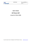
2.4.3 UART Interface
The UC1394a-3 MCM has an UART interface that can be used for standard asynchronous
communication. Different baud rates and RTS/CTS handshake are supported. The Ultra Compact
Small Carrier uses a level converter to convert these signals to RS-232 level. The RS-232 signals
are routed to a 10-pin connector on the UV1394a Small Carrier board. The UART signals are also
routed to MCM connector A at 3.3V LVTTL. These signals can be used to control the camera /
image sensor. To convert these signals to RS-232 an external level converter is required. For a
connection example please refer to [15].
Figure 4: UART interface block diagram
The UART interface is often used as debug interface connected to a PC-based terminal program
during the software development phase. Then the UART can not be used to control a camera /
image sensor. The module support library described in chapter 6 provides functions that support
the use of the UART as debug interface. Most of the application examples use the UART as debug
interface.
Signal
Connector
Carrier PCB 10-pin
TxD
RxD
RTS
CTS
GND
5
3
4
8
9, 10
Cable connection to a remote PC
Sub-D 9Sub-D 25-pin
pin
2
3
3
2
8
5
7
4
5
7
Table 1: UART connector pin assignments
2.4.4 8-bit HPI or General-purpose I/O
The DSP provides an 8-bit host port interface. The HPI is accessed by an external host. This
interface can be used for controlling intelligent cameras that have an own micro-controller.
The host port pins can alternatively be used as general-purpose I/O-pins. When configured as
general-purpose I/O, these pins can be used for bit level digital I/O. Each pin can be configured
individually as input or output.
USER’S GUIDE
DCAM CAMERA DEVELOPMENT KIT
Date
: 26 January 2007
Doc. no. : DCAM_Camera_DevKit_UG
Iss./Rev : 1.00
Page
: 14
The HPI and general-purpose I/O pins can be programmed on register level, which is described in
[6]. A slightly higher level of access is provided by TI’s chip support library, that is part of Code
Composer Studio.
2.4.5 McBSP Interfaces
The DSP provides two McBSP interfaces. The McBSPs are high-speed serial interfaces that can
be used for controlling cameras that require a synchronous serial interface. They support a lot of
different operation modes, such as SPI or AC97. The McBSP interfaces can be programmed on
register level, which is described in [8]. A slightly higher level of access is provided by TI’s chip
support library, that is part of Code Composer Studio.
2.4.6 I2C Interface
The DSP provides an I2C interface. This interface supports the I2C bus specification V2.1, DMA
events for automated transfers, interrupts and free data formats. This interface can be used for
controlling digital cameras that have an I2C control interface. The I2C interface can be programmed
on register level, which is described in [9]. A slightly higher level of access is provided by TI’s chip
support library, that is part of Code Composer Studio.
2.4.7 Timer Signals
The DSP provides two timers with an input / output signal each. These signals can be used as
general-purpose I/O to control cameras. The timer signals can be programmed on register level,
which is described in [5]. A slightly higher level of access is provided by TI’s chip support library,
that is part of Code Composer Studio.
2.4.8 XF Output
This pin can be used as general-purpose output pin to control cameras. XF is set high by the
BSET XF") instruction and set low by the asm(" BCLR XF") instruction.
asm("
2.4.9 LED
The LED of the UC1394a-3 is available for user control and can be used for optical display or
diagnostics. Controlling the LED is described in chapter 6.4.
2.4.10 JTAG Connector
The JTAG connector provides the JTAG signals of both, the CPU and the FPGA of the MCM. The
JTAG interfaces are typically used with the respective download cables or emulators. For
development kits, a JTAG adapter is included that provides suitable connectors for the download
cables and emulators. Please refer to [15] for a description of the pinning of the JTAG connector.
A13
A1
B13
B1
+3.3V GND TCK TDO TDI TMS
FPGA JTAG c onnec tor
DSP JTAG c onnec tor
(fits TI emulator POD)
top view
Figure 5: JTAG Adapter
The DSP JTAG interface is used for downloading and debugging DSP software. It is used with a
JTAG emulator, such as the TI XDS series, which can be connected to the carrier board by an
adapter. The JTAG adapter is included in the DCAM Camera Development Kit.
Usually, the JTAG connector is used in conjunction with the JTAG adapter. This JTAG adapter
provides connectors which are compatible with standard development tools:
• the Texas Instruments emulator cables, such as the XDS510 or compatible
• the Xilinx parallel download cable
USER’S GUIDE
DCAM CAMERA DEVELOPMENT KIT
Date
: 26 January 2007
Doc. no. : DCAM_Camera_DevKit_UG
Iss./Rev : 1.00
Page
: 15
The FPGA JTAG interface is used with programming hardware, such as the Xilinx parallel
download cable. A JTAG adapter, which is included in the DCAM Camera Development Kit,
provides a suitable connector.
FPGA development for the MCM or the carrier board is available as a separate product.
2.4.11 Power Supply Input
The UC1394a-3 MCM requires a single, regulated 3.3 V power supply. The Ultra-Compact Small
Carrier generates this voltage.
The Power supply of the carrier can be provided by three different ways:
• From the DC power input socket (J7)
• From the IEEE1394 cable (over J8 or J9)
• Over the direct MCM connectors (J1, J2; requires modification of the carrier)
For a detailed description of the power supply please refer to [18].
USER’S GUIDE
DCAM CAMERA DEVELOPMENT KIT
Date
: 26 January 2007
Doc. no. : DCAM_Camera_DevKit_UG
Iss./Rev : 1.00
Page
: 16
3 Getting Started
The UC1394a-3 DCAM Camera Development Kit is shipped with the application example
camera_uart already stored in flash memory. This allows to do the very fist steps with the kit
without development tools required. The camera_uart example uses the DCAM camera API to
implement an IIDC 1394-compliant digital camera and prints some messages to the RS-232
interface. Below is a procedure for doing the first steps with the DCAM Camera Development Kit.
Required items:
• the UC1394a-3 DCAM Camera Development Kit
• an IEEE1394 cable and a RS-232 cable
• a PC with
Windows XP
an IEEE1394 interface
a terminal program, such as HyperTerminal
Steps to be performed:
• start a terminal program, such as “HyperTerminal” on the PC
• set up the terminal program to 115200 bits per second, 8 data bits, no parity, 1 stop bit and
hardware flow control
• connect the UC1394a-3 DCAM Camera Development Kit to the PC using the RS_232
cable
• connect the UC1394a-3 DCAM Camera Development Kit to the PC using the IEEE1394
cable
• The PC recognizes the UC1394a-3 Camera Development Kit as an IIDC compliant camera,
loads a high-level driver for the IIDC device class and initializes the camera. Camera
initialization is also indicated on the terminal output, after the startup messages from the
camera_uart example:
•
Click on "Start", then on "My computer"
USER’S GUIDE
DCAM CAMERA DEVELOPMENT KIT
Date
: 26 January 2007
Doc. no. : DCAM_Camera_DevKit_UG
Iss./Rev : 1.00
Page
: 17
•
The Camera Development Kit must now be displayed as "Generic 1394 Desktop Camera":
•
If the camera is opened by a double-click, the PC sets up and starts the camera. No
images are displayed, because no image data source is connected to the kit's camera
interface. However, interaction between PC and the camera can be seen on the terminal
output:
The application example camera_uart is described in detail in chapter “Application Examples” in
[17].
USER’S GUIDE
DCAM CAMERA DEVELOPMENT KIT
Date
: 26 January 2007
Doc. no. : DCAM_Camera_DevKit_UG
Iss./Rev : 1.00
Page
: 18
4 Programming the UC1394a-3
This chapter describes general software development for the UC1394a-3 with the DCAM Camera
Development Kit.
The UC1394a-3 provides the following programming interfaces:
• DCAM Camera API (see [17])
• Module support library (see chapter 5.6)
• Register-level programming of FPGA registers (see [16])
• On-chip peripherals of the TMS320VC5501/5502 (see [5])
The on-chip peripherals can also be programmed at a slightly higher level using TI’s chip support
library, which is part of Code Composer Studio.
4.1
Required Items
•
•
•
•
•
4.2
a development PC
a JTAG emulator, from Texas Instruments (e.g. XDS510) or from another vendor
Code Composer Studio (CCS) from Texas Instruments, version 3.1 or higher
Ultra-Compact Small Carrier or another suitable power supply
optional: a terminal program, such as HyperTerminal and a RS-232 cable
Software Development Flow
User-defined software can be written as C-source code. The source code modules are compiled by
the C-compiler. The resulting object files must be linked with at least the run-time library for the
TMS320VC5501/5502 (rts55x.lib). Usually, one or more object libraries are added during the
linker process, such as the DCAM camera API libraries and the module support library. The output
of the linker is an executable file, which can be downloaded to the UC1394a-3 over the JTAG
interface using an emulator. To store the user application permanently in flash memory, the .out file
must be converted to a boot data stream by the hex conversion tool. To program this boot data
stream, the FlashBurn application on the PC must be started. The FlashBurn application
•
•
loads the Flash Burn Target Component (FBTCOrsysUC1394a-3.out) to the UC1394a-3
and starts it
sends the boot data stream to FBTCOrsysUC1394a-3.out, that in turn programs it to the
flash memory.
Further details on flash programming can be found in chapter 4.4.
This development flow is shown in the picture below. The distribution contains some project
examples which perform this development flow.
USER’S GUIDE
DCAM CAMERA DEVELOPMENT KIT
Date
: 26 January 2007
Doc. no. : DCAM_Camera_DevKit_UG
Iss./Rev : 1.00
Page
: 19
Figure 6: Software development flow
4.3
Running an Application with Code Composer Studio
•
•
•
connect the kit to the development PC using the JTAG emulator and the RS-232 cable
(optional)
for the camera_stdio and camera_uart examples connect the kit to a host, using the
IEEE1394 cable.
power on the system
USER’S GUIDE
DCAM CAMERA DEVELOPMENT KIT
•
•
•
•
•
•
•
Date
: 26 January 2007
Doc. no. : DCAM_Camera_DevKit_UG
Iss./Rev : 1.00
Page
: 20
start Code Composer Studio
select the "Load GEL..." command from the "File" menu
locate UC1394a-3_camera_bsp.gel from the GEL folder on the distribution media and open
it
select the "Initialization" → " “CPU_reset_and_init_300" or “CPU_reset_and_init_200”
command from the "GEL" menu1
select the "Load Program..." command from the "File" menu
locate one of the application examples from the examples folder on the distribution media
and open it (e.g. toggle_led.out)
select the "Run" command from the "Debug" menu
Please note: most application examples do not use the usual printf function. Instead, where
necessary, output is sent over the RS-232 interface. This allows to store the examples in flash
memory and then to execute them without the JTAG emulator. Before running applications using
the RS-232 interface a terminal program should be started on the PC.
The terminal program must be set up as follows:
baud rate
115200
bits per character
8
parity
none
stop bits
1
handshake
RTS/CTS (hardware handshake)
The pin assignment to connect to a PC is described in Table 1.
4.3.1 Debugging of the Software
Select the "Halt" command from the "Debug" menu. CCS will stop the DSP (from toggling the LED
in case of the toggle_led example) and it displays the current instruction in the disassembly
window and in the source code window. Now you can use all debugging features that CCS
provides, such as breakpoints, single stepping, and so on. For details, please refer to the CCS online help and documentation.
1
For the DCAM Camera Development Kit, operation at 200MHz CPU clock is recommended.
USER’S GUIDE
DCAM CAMERA DEVELOPMENT KIT
4.4
Date
: 26 January 2007
Doc. no. : DCAM_Camera_DevKit_UG
Iss./Rev : 1.00
Page
: 21
Programming an Application into Flash Memory
The UC1394a-3 supports up to 832KB of flash memory for application code. This application code
must be in a format suitable for the processor's boot loader. To generate such a file, the projects
on the distribution CD contain a final build step that uses the hex55 utility. To program your
application into the UC1394a-3's flash memory, you must
• Connect the JTAG emulator to the UC1394a-3.
• Start Code Composer Studio.
• Open your project.
• Build the project as normal.
• Select the "Initialization" → "MCM_init_200MHz" command from the "GEL" menu.
• Start the FlashBurn utility.
• The FlashBurnDSK utility starts up, showing the "FlashBurn Startup" window.
• Select "Create a new FlashBurn configuration" and click on "OK".2
• In "Section 1: Connect to a Target" select a suitable connection, such as "C5501 XDS510
Emulator (CPU_1)". For most CCS installations there is only one option available. Then,
click on the "Connect" button.
• In "Section 2: Download the FlashBurn Target Component (FBTC)" click on the "..." button,
locate FBTCOrsysUC1394a-3.out (folder named host\FlashBurnDSK on the distribution
media) and open it.
• Click on the "Download FBTC" button and verify that the chain symbol left of this button
changes to a closed chain.
• In "Section 3: Program Flash Memory" click on the "..." button right of "File to Burn", locate
the application code that is to be programmed, e.g. toggle_led.hex and open it.
• Click on the "Erase Flash" button. The erase process takes about 8..12 seconds to
complete.
• Click on the "Program Flash" button.
• Now your application is programmed to flash memory and will boot at the next system start.
• To save the settings for later usage, select "Save As..." from the "File" menu, select an
appropriate name and location for the file and click on "Save".
• if problems occur during one of the above steps, the following steps could help:
o select "Show Code Composer" from the "View" menu
o change to Code Composer Studio
o select the "Initialization" → "MCM_init_200MHz" command from the "GEL" menu
o select the "Reload Program" command from the "File" menu
o select the "Run" command from the "Debug" menu
o Now Code Composer Studio must display the cursor at DoMessageProc in the
disassembly window
o change back to the FlashBurn utility and repeat the procedure
Further help can be found in the help menu of Code Composer Studio. The FlashBurnDSK utility is
included in the Orsys distribution.
4.5
Startup Procedure
After power-up or a system reset, the DSP starts its internal boot loader. The boot loader initializes
the MCM according to the information of the boot header. Then, it loads the application from flash
memory into RAM and starts program execution at the specified address. This is the default startup
procedure in end-system environment. During development the startup procedure looks a little bit
different:
2
The examples provided with the DCAM Camera Development Kit already have predefined FlashBurnDSK
configuration files. To use them, please select "Open an existing FlashBurn Configuration" instead.
USER’S GUIDE
DCAM CAMERA DEVELOPMENT KIT
Date
: 26 January 2007
Doc. no. : DCAM_Camera_DevKit_UG
Iss./Rev : 1.00
Page
: 22
After power-up or a system reset, the DSP starts its internal boot loader. The boot loader tries to
load an application from flash, which may succeed or leave the DSP in an unknown state. The user
starts Code Composer Studio, loads UC1394a-3_camera_bsp.gel and puts the DSP to an
initialized state by selecting the "MCM_init_200MHz" command from the "GEL" → "Initialization"
menu. Now the user application can be loaded, executed and debugged using the emulator.
4.6
Hints for Programming the TMS320VC5501/5502
4.6.1 A Byte is 16 Bits
Please note, that these DSPs can only access data in units of 16 bit. Even a character array will
consist of 16 bit. The screenshots below illustrate this.
Figure 7: Memory view of a string in character format
Figure 8: Memory view of a string in binary format
Further information can be found in [10]; chapter "Memory and I/O space" and in [12]; chapter
"Data types"
4.6.2 64K Page Limit
The TMS320C5000 series of DSPs use a 16-bit architecture, which adds restrictions to pointer
accesses. Although the DSP as well as the C-compiler support 23-bit pointers, pointer
manipulation is always done modulo 64K. Below is a code example that shows how to handle
arrays which cross 64K boundaries.
/* wrong, will stay in the lower 64K bytes */
static int array[100000];
int i;
for (i = 0; i < sizeof(array); i++)
array[i] = 0;
/* correct: use a cast to calculate the pointer for each access */
static int array[100000];
unsigned long i;
for (i = (unsigned long)array;
i < (unsigned long array) + sizeof(array);
i++)
*(unsigned long *)i = 0;
4.6.3 Pipeline
Accesses to memory may take some clock cycles until they are completed, since the execution is
broken down into several pipelined steps. For memory accesses this is no problem. However,
accesses to hardware registers can lead to unexpected results. One example is disabling
interrupts:
asm("
asm("
asm("
asm("
asm("
asm("
asm("
BSET INTM");
NOP");
NOP");
NOP");
NOP");
NOP");
NOP");
Without the NOP instruction, an interrupt can occur immediately after the BSET INTM instruction.
The execution of the NOPs ensures, that all stages of the BSET INTM instruction have been
performed before further code is executed. The NOPs must be inserted only if the code
immediately following the BSET INTM instruction must be protected against interrupts.
USER’S GUIDE
DCAM CAMERA DEVELOPMENT KIT
Date
: 26 January 2007
Doc. no. : DCAM_Camera_DevKit_UG
Iss./Rev : 1.00
Page
: 23
Another point is access to peripherals in a write-read back fashion. Since a write access takes
longer to be performed than a read access, the read may occur before the write, resulting in
outdated data. When reading back data that has just been written, two NOP instructions should be
inserted between write and read. Below is an example taken from the flash programming routines:
/* Wrong, do not use that */
for (ulWords = 0; ulWords < ulLengthInWords; ulWords++)
{
// enter programming mode
*(volatile INT16U*) (UC1394A3_FLASH_BASE + 0x0555) = 0xAA;
*(volatile INT16U*) (UC1394A3_FLASH_BASE + 0x02AA) = 0x55;
*(volatile INT16U*) (UC1394A3_FLASH_BASE + 0x0555) = 0xA0;
........// write data word to flash
*(volatile INT16U*)ulFlashAdr = *(volatile INT16U*)ulDataAdr;
........// wait until programmed
while (*(volatile INT16U*)ulFlashAdr != *(volatile INT16U*)ulDataAdr)
asm(" NOP");
ulFlashAdr++;
ulDataAdr++;
if ((ulWords & FLASH_PRG_CALLBACK_RATIO) == 0 &&
pCallback != NULL)
pCallback();
}
/* corrected code */
for (ulWords = 0; ulWords < ulLengthInWords; ulWords++)
{
// enter programming mode
*(volatile INT16U*) (UC1394A3_FLASH_BASE + 0x0555) = 0xAA;
*(volatile INT16U*) (UC1394A3_FLASH_BASE + 0x02AA) = 0x55;
*(volatile INT16U*) (UC1394A3_FLASH_BASE + 0x0555) = 0xA0;
........// write data word to flash
*(volatile INT16U*)ulFlashAdr = *(volatile INT16U*)ulDataAdr;
// The following NOP's causes the write operation to finish before
// the programming status is read. Otherwise, the pipeline could
// exchange write and read, which causes a premature abort.
asm(" NOP");
asm(" NOP");
........// wait until programmed
while (*(volatile INT16U*)ulFlashAdr != *(volatile INT16U*)ulDataAdr)
asm(" NOP");
ulFlashAdr++;
ulDataAdr++;
if ((ulWords & FLASH_PRG_CALLBACK_RATIO) == 0 &&
pCallback != NULL)
pCallback();
}
USER’S GUIDE
DCAM CAMERA DEVELOPMENT KIT
Date
: 26 January 2007
Doc. no. : DCAM_Camera_DevKit_UG
Iss./Rev : 1.00
Page
: 24
5 Application Examples
The distribution media contains two kinds of application examples:
• Examples that demonstrate the use of the module support library
• Examples that demonstrate the use of the camera BSP and the DCAM Camera API
The examples are described in the subsequent sections. The examples can be run and debugged
using Code Composer Studio as described in chapter 4.3 or they can be programmed to the flash
memory as described in chapter 4.4.
All application examples are provided as a CCS project. The project has two available
configurations: Debug and Release. Debug is the default configuration and should be used during
development. The Release configuration differs from Debug in two points:
•
•
no debugging symbols are created, the code is not suitable for source code debugging, but
better optimized and smaller
the Release version of the module support library is used
The Release configuration should be used for the final application after development is finished.
Further, all example projects contain a final build step that creates a .hex file. This file can be
programmed to flash memory as described in chapter 4.4.
USER’S GUIDE
DCAM CAMERA DEVELOPMENT KIT
Date
: 26 January 2007
Doc. no. : DCAM_Camera_DevKit_UG
Iss./Rev : 1.00
Page
: 25
5.1
LED Control (toggle_led)
This is the most basic application example. It initializes the MCM and then enters a main loop. The
main loop just toggles the MCM's LED. After loading and starting this example. the MCM's LED is
blinking. This application example can be used as a rudimentary test to check if the kit and the
MCM are working properly.
5.2
UART (hello)
This example shows how to program the UART of the DSP using driver functions from the module
support library. First, the MCM is set up. Then, the UART is initialized for 115200 baud and
hardware (RTS/CTS) handshake. Then, an output message is assembled using the stdio function
sprintf. The output message contains some information about the MCM. The output message is
sent to the RS-232 interface. Finally, the main loop is entered. In the main loop, the UART
interface is checked for incoming characters. Whenever a character comes in, it is simply echoed.
Figure 9: Sample session of the hello example
5.3
Buffered Character I/O (dbg_out)
This example uses the UART interface at a higher level of abstraction: buffered character I/O, as
provided by the module support library, see chapter 5.6 for details. This is an alternative to using
the stdio functions, such as sprintf, sscanf, etc. dbg_out prints out the same startup message as
hello, but the main loop is programmed as a command interpreter. This shows how to implement
an application that is interactively controlled over RS-232. Pressing the '?' key within the terminal
program causes a help page to be displayed. Other command keys can easily be added by
inserting appropriate case statement in the command switch. Below is an example that shows how
insert a command that toggles the MCM LED by pressing the key 't':
USER’S GUIDE
DCAM CAMERA DEVELOPMENT KIT
Date
: 26 January 2007
Doc. no. : DCAM_Camera_DevKit_UG
Iss./Rev : 1.00
Page
: 26
// below is a command switch that could be used in applications
// that require user interaction over RS_232
switch(c)
{
case '?':
case 'h':
DebugOutConstString("Debug interface example\r\n");
DebugOutConstString("'h' and '?' show this help page\r\n"
"no other commands/keys defined\r\n");
break;
case 't':
// toggle the red MCM LED
UC1394A3_SYS_CTL ^= UC1394A_SYS_LED;
break;
default:
DebugOutConstString("invalid command. "
"'?' shows a help page.\r\n");
break;
}
}
5.4
MCM Information Utility (mcm_info)
The mcm_info utility loads the FPGA from flash memory and displays the following information:
• FPGA version
• FPGA revision
• Flash memory manufacturer
• Flash memory device code
This utility can be used to find out what FPGA code is currently installed in flash memory.
5.5
Image Source Information Utility (sensor_check)
The sensor_check utility uses the camera BSP to get as much information as possible from an
image source connected to the camera interface. It can be useful when doing the first steps with an
image source to verify that correct settings are used and operation of the camera interface is
stable. To use this utility, an already running image source must be connected to the camera
interface.
USER’S GUIDE
DCAM CAMERA DEVELOPMENT KIT
5.6
Date
: 26 January 2007
Doc. no. : DCAM_Camera_DevKit_UG
Iss./Rev : 1.00
Page
: 27
DCAM Application Examples
These examples use the DCAM Camera API to implement an IIDC 1394-compliant digital camera.
For a detailed description of the examples please refer to chapter “Application Examples” in [17].
USER’S GUIDE
DCAM CAMERA DEVELOPMENT KIT
Date
: 26 January 2007
Doc. no. : DCAM_Camera_DevKit_UG
Iss./Rev : 1.00
Page
: 28
6 Module Support Library
The module support library is a collection of functions that are commonly used when programming
the UC1394a-3 MCM. The code in this library is usually not changed by the user. During software
development, this library is simply added to the project. However, the source code is provided for
reference and for cases where a customization is necessary. A CCS project for creating the
module support library is also provided. Please note: after compiling the library sources, the
compiled libraries reside in the respective output directories (Debug and/or Release). For using
them with the example projects, they must be copied to the lib\Release and lib\Debug directories.
6.1
Module Support Library Modules
The module support library contains the following modules:
Module
init.c
fpgaload.c
uart.c
flash.c
debug.c
hexutil.c
decutil.c
Contents
module support functions
FPGA loader
UART routines
flash programming routines
simple, buffered I/O over the UART interface
binary to hexadecimal ASCII conversion
binary to decimal ASCII conversion
Below is a brief description of each module. The functions of module are explained in chapter 6.5.
6.1.1 init.c
This module defines initialization and utility functions for the MCM, such as interrupt control.
6.1.2 fpgaload.c
This module contains a loader for FPGA code. The FPGA must be loaded using this loader at
system startup. FPGA resources are only available after loading.
6.1.3 uart.c
This module contains functions to control the UART of the TMS320C5501/5502 DSP.
6.1.4 flash.c
Contains flash programming routines. It is recommended that application software does not modify
the flash memory. Instead, the provided methods for accessing the flash memory should be used
(FlashBurn utility for application code programming (see chapter 4.5) or FPGA flasher executable
for updating / programming FPGA code).
6.1.5 debug.c
This module contains a simple system for buffered character I/O over the UART interface.
Typically, the functions of this module are not used directly, but over associated macros (see
chapter 6.4). debug.c can be used as an alternative for the stdio functions (e.g. printf), especially,
when small code size is required or no emulator is available.
6.1.6 hexutil.c
Utility functions that convert binary values to hexadecimal ASCII.
6.1.7 decutil.c
Utility functions that convert binary values to decimal ASCII.
USER’S GUIDE
DCAM CAMERA DEVELOPMENT KIT
6.2
Module Support Library Header Files
Contains function prototypes for the main part of the module support library,
such as initialization and interrupt management.
Defines the FPGA registers and includes basic hardware definitions of the
UC1394a-3 equipped with the Camera BSP.
functions for loading the FPGA.
Defines a simple, buffered character I/O interface using the UART
interface. Suitable for debugging output as well as general character I/O.
msl.h
camera_bsp.h
fpgaload.h
debug.h
6.3
Date
: 26 January 2007
Doc. no. : DCAM_Camera_DevKit_UG
Iss./Rev : 1.00
Page
: 29
Global Variables Reference
6.3.1 Clock Rates
The variables below contain the clock rates of the DSP. The function InitDSP sets up the clock
rates and then initializes the variables. These variables can be used to calculate software
controlled timings.
Clock rates initialized by InitDSP:
INT32U
INT32U
INT32U
INT32U
ulSysclk1;
ulSysclk2;
ulSysclk3;
ulClkout3;
//
//
//
//
fast peripherals (DMA, HPI, Timer)
slow peripherals (McBSP, I2C, UART)
EMIF
CPU
6.3.2 Interrupt Vector Table
The module support library maintains an interrupt vector table. This table is initialized by InitDSP.
User interrupt handlers can be inserted by calling IntHook. The table is accessible from outside of
the module support library in order to better support debugging. Directly accessing the interrupt
vector table should be avoided.
// interrupt vector table
extern struct
{
void (*handler) (void);
INT32U dummy;
} vectab[32];
6.4
Macros Reference
This chapter lists the macros that are defined by the module support library. Currently, the only
available macros are utility functions for debug.c and macros to control the red LED of the
UC1394a-3 MCM.
6.4.1 DebugOutByteHex
Converts a 8-bit number into a string (hexadecimal) and puts the string into the debug transmit
buffer. This is a macro that calls the functions HexByte2Ascii and DebugPuts.
defined in
debug.h
synopsis
void DebugOutByteHex(INT8U digit);
parameters
digit
8-bit number to convert and put to the debug interface
USER’S GUIDE
DCAM CAMERA DEVELOPMENT KIT
Date
: 26 January 2007
Doc. no. : DCAM_Camera_DevKit_UG
Iss./Rev : 1.00
Page
: 30
return value
none
6.4.2 DebugOutConstString
Puts a string into the debug transmit buffer. This is a macro that calls the function DebugPuts. It is
intended for constant string output , such as DebugOutConstString("Hello, world\r\n");. Pointers to
strings will fail because the length of the string is not known at compile time.
defined in
debug.h
synopsis
INT16U DebugOutConstString(char cString[]);
parameters
cString[]
output string for the debug interface
return value
number of characters actually written
6.4.3 DebugOutDwordHex
Converts a 32-bit number into a string (hexadecimal) and puts the string into the debug transmit
buffer. This is a macro that calls the functions HexLong2Ascii and DebugPuts.
defined in
debug.h
synopsis
void DebugOutDwordHex(INT32U digit);
parameters
digit
32-bit number to convert and put to the debug interface
return value
none
6.4.4 DebugOutNibbleHex
Converts a 4-bit number (lower 4 bits of 8-bit number) into a string (hexadecimal) and puts the
string into the debug transmit buffer. This is a macro that calls the functions HexNibble2Ascii and
DebugPuts.
defined in
debug.h
synopsis
void DebugOutNibbleHex(INT8U digit);
parameters
digit
8-bit number to convert and put to the debug interface
USER’S GUIDE
DCAM CAMERA DEVELOPMENT KIT
Date
: 26 January 2007
Doc. no. : DCAM_Camera_DevKit_UG
Iss./Rev : 1.00
Page
: 31
return value
none
6.4.5 DebugOutSByteDec
Converts a signed 8-bit number into a string of 4 characters and puts the string into the debug
transmit buffer. This is a macro that calls the functions DecSignedByte2Ascii and DebugPuts.
defined in
debug.h
synopsis
void DebugSByteDec(INT8S digit);
parameters
digit
number to convert and put to the debug interface
return value
none
6.4.6 DebugOutSDwordDec
Converts an signed 32-bit number into a string of 11 characters and puts the string into the debug
transmit buffer. This is a macro that calls the functions DecSignedDword2Ascii and DebugPuts.
defined in
debug.h
synopsis
void DebugOutsDwordDec(INT32S digit);
parameters
digit
number to convert and put to the debug interface
return value
none
6.4.7 DebugOutSNibbleDec
Converts a signed 4-bit number into a string of two characters and puts the string into the debug
transmit buffer. This is a macro that calls the functions DecSignedNibble2Ascii and DebugPuts.
defined in
debug.h
synopsis
void DebugOutSNibbleDec(INT8S digit);
parameters
digit
number to convert and put to the debug interface
return value
none
6.4.8 DebugOutString
Puts a string into the debug transmit buffer. This is a macro that calls the function DebugPuts.
Pointers to strings are allowed since the length of the string is determined at run time.
USER’S GUIDE
DCAM CAMERA DEVELOPMENT KIT
Date
: 26 January 2007
Doc. no. : DCAM_Camera_DevKit_UG
Iss./Rev : 1.00
Page
: 32
defined in
debug.h
synopsis
INT16U DebugOutString(char *pString);
parameters
pString
pointer to output string for debug the interface
return value
number of characters actually written
6.4.9 DebugOutSWordDec
Converts a signed 16-bit number into a string of 6 characters and puts the string into the debug
transmit buffer. This is a macro that calls the functions DecSignedWord2Ascii and DebugPuts.
defined in
debug.h
synopsis
void DebugOutSWordDec(INT16S digit);
parameters
digit
number to convert and put to debug the interface
return value
none
6.4.10 DebugOutUByteDec
Converts an unsigned 8-bit number into a string of 3 characters and puts the string into the debug
transmit buffer. This is a macro that calls the functions DecUnsignedByte2Ascii and DebugPuts.
defined in
debug.h
synopsis
void DebugOutUByteDec(INT8U digit);
parameters
digit
number to convert and put to the debug interface
return value
none
6.4.11 DebugOutUDwordDec
Converts an unsigned 32-bit number into a string of 10 characters and puts the string into the
debug transmit buffer. This is a macro that calls the functions DecUnsignedDword2Ascii and
DebugPuts.
defined in
debug.h
synopsis
void DebugOutUDwordDec(INT32U digit);
USER’S GUIDE
DCAM CAMERA DEVELOPMENT KIT
parameters
digit
Date
: 26 January 2007
Doc. no. : DCAM_Camera_DevKit_UG
Iss./Rev : 1.00
Page
: 33
number to convert and put to the debug interface
return value
none
6.4.12 DebugOutUNibbleDec
Converts an unsigned 4-bit number into a string of two characters and puts the string into the
debug transmit buffer. This is a macro that calls the functions DecUNibble2Ascii and DebugPuts.
defined in
debug.h
synopsis
void DebugOutUNibbleDec(INT8U digit);
parameters
digit
number to convert and put to the debug interface
return value
none
6.4.13 DebugOutUWordDec
Converts an unsigned 16-bit number into a string of 5 characters and puts the string into the debug
transmit buffer. This is a macro that calls the functions DecUnsignedWord2Ascii and DebugPuts.
defined in
debug.h
synopsis
void DebugOutUWordDec(INT16U digit);
parameters
digit
number to convert and put to the debug interface
return value
none
6.4.14 DebugOutWordHex
Converts a 16-bit number into a string (hexadecimal)) and puts the string into the debug transmit
buffer. This is a macro that calls the functions HexWord2Ascii and DebugPuts.
defined in
debug.h
synopsis
void DebugOutWordHex(INT16U digit);
parameters
digit
return value
none
16-bit number to convert and put to the debug interface
USER’S GUIDE
DCAM CAMERA DEVELOPMENT KIT
Date
: 26 January 2007
Doc. no. : DCAM_Camera_DevKit_UG
Iss./Rev : 1.00
Page
: 34
6.4.15 UC1394A3_LED_ON
Turns the red LED of the UC1394a-3 MCM on. Defined in uc1394a-3.h.
6.4.16 UC1394A3_LED_OFF
Turns the red LED of the UC1394a-3 MCM off. Defined in uc1394a-3.h.
6.4.17 UC1394A3_LED_TOGGLE
Toggles the red LED of the UC1394a-3 MCM. Defined in uc1394a-3.h.
6.5
Functions Reference
This chapter gives a brief description of the module support library functions.
6.5.1 InitDSP
Configures the DSP to work with the peripherals. Sets up processor clock and EMIF settings. Sets
up and initializes the interrupt vector table. Interrupts are disabled globally during initialization an
are enabled again when InitDSP returns. Further, all maskable interrupts are disabled and cleared.
Interrupt vectors are set up to a table managed by the module support library. The interrupt vector
table is initialized with dummy interrupt handlers (DefaultISRx()) in order to get deterministic
behavior when uninitialized interrupts are triggered.
defined in
msl.h
synopsis
void InitDsp(INIT_MODE eMode);
parameters
none
return value
none
6.5.2 IntHook
defined in
msl.h
Description
Installs an interrupt handler for the given interrupt number in the interrupt vector table. The interrupt
numbers are defined in c5501.h. The interrupt handler must be defined with the interrupt keyword.
synopsis
void IntHook (int iIntNumber, void (*pHandler)(void));
parameters
int iIntNumber
pHandler
number of interrupt to be inserted
pointer to the interrupt handler
return value
none
6.5.3 IntEnable
Enables the specified interrupt in the corresponding Interrupt Enable Register. The interrupt
numbers are defined in c5501.h.
USER’S GUIDE
DCAM CAMERA DEVELOPMENT KIT
Date
: 26 January 2007
Doc. no. : DCAM_Camera_DevKit_UG
Iss./Rev : 1.00
Page
: 35
defined in
msl.h
synopsis
void IntEnable (int iIntNumber)
parameters
int iIntNumber
number of interrupt to be enabled
return value
none
6.5.4 IntDisable
Disables the specified interrupt in the corresponding Interrupt Enable Register. The interrupt
numbers are defined in c5501.h.
defined in
msl.h
synopsis
void IntDisable (int iIntNumber)
parameters
int iIntNumber
number of interrupt to be disabled
return value
none
6.5.5 IntClear
Clears the specified interrupt in the corresponding Interrupt Flag Register if pending. The interrupt
numbers are defined in c5501.h.
defined in
msl.h
synopsis
void IntClear (int iIntNumber)
parameters
iIntNumber
number of interrupt to be cleared (see c5501.h)
return value
none
6.5.6 FpgaLoad
Loads code to the FPGA (usually from flash memory). Default address when loading the FPGA
code from flash is UC1394A3_FLASH_FPGA_CODE. The code length can be retrieved from the code's
header by specifying UC1394A3_FLASH_FPGA_LENGTH. When the FPGA code is linked to the application,
the parameters must be modified accordingly. Please note: The FPGA code is usually preceded by
a header. FpgaLoad() supports both, code with and without header. Care must be taken to specify
the correct length for each variant. The length is of the header is 28 bytes for each variant.
defined in
fpgaload.h
USER’S GUIDE
DCAM CAMERA DEVELOPMENT KIT
Date
: 26 January 2007
Doc. no. : DCAM_Camera_DevKit_UG
Iss./Rev : 1.00
Page
: 36
synopsis
int FpgaLoad(INT32U *pData, INT32U ulLength);
parameters
pData
ulLength
pointer to FPGA image in flash memory
length of FPGA image in bytes
return value
(zero) if FPGA image is loaded successfully, otherwise the FPGA has not been
loaded. Possible reasons for this are:
the flash area for FPGA code is not programmed or contains invalid data
the FPGA Code was created for a non-matching device
the FPGA Code was created with incorrect programming file options.
FPGA_SUCCESS
6.5.7 FlashGetDeviceInfo
Reads manufacturer and device ID from the flash and stores them in the specified locations.
Default manufacturer ID is 000116 (AMD) or 00C216 (Macronix). Default device ID is 225B16
(29LV800).
defined in
msl.h
synopsis
void FlashGetDeviceInfo(INT16U *pManufacturer, INT16U *pDevice, void (*pCallback)(void));
parameters
pManufacturer
pDevice
pointer to location where manufacturer ID is stored
pointer to location where device ID is stored
return value
None
6.5.8 FlashEraseSector
Erases the specified sector. During the erase process, a user-specified callback function is
executed to allow the application to continue processing or to indicate the progress of the
operation. The callback is called whenever the erase status is queried. Since the flash memory is
completely used for storing application and FPGA code (see chapter “Flash Memory” in [15]),
application software should not modify the flash contents.
defined in
msl.h
synopsis
void FlashEraseSector(int iSector, void (*pCallback)(void));
parameters
iSector
pCallback
return value
FLASH_OK
Sector number to be erased. Allowed values: 0 .. 15.
Pointer to a user callback function. Must be set to a valid user callback
function or to NULL if no callback is used.
Operation was successful
USER’S GUIDE
DCAM CAMERA DEVELOPMENT KIT
Date
: 26 January 2007
Doc. no. : DCAM_Camera_DevKit_UG
Iss./Rev : 1.00
Page
: 37
6.5.9 FlashProgram
Programs data into a previously erased area. During programming, a user-specified callback
function is executed to allow the application to continue processing or to indicate the progress of
the operation. The callback is called each time when 100 words have been programmed to the
flash. After programming, the programmed data is verified.
defined in
msl.h
synopsis
int FlashProgram(INT32U ulStartOffset, INT32U ulLengthInWords, INT16U *pusData,
void (* pCallback)(void));
parameters
ulStartOffset
ulLengthInWords
pusData
pCallback
Destination offset relative to start of the flash, specified in 16-bit words.
Allowed values: 0000000016 ... 000C000016, or one of
UC1394A3_FLASH_SA0_OFFS ... UC1394A3_FLASH_SA15_OFFS.
Number of 16-bit words to program.
Points to the source data.
User callback function.
return value
FLASH_OK
FLASH_COMPARE_ERROR
Programming was successful.
Verification of the programmed data failed.
6.5.10 DebugBufmgr
Writes one character form the debug transmit buffer to the debug interface if there is data in the
transmit buffer and the underlying debug interface is ready to accept it.
Reads one character from the debug interface to the debug receive buffer if data is available and
the buffer is not already full.
The function doesn’t operate interrupt-driven, so it must be called periodically.
defined in
debug.h
synopsis
void DebugBufmgr(void);
parameters
none
return value
none
USER’S GUIDE
DCAM CAMERA DEVELOPMENT KIT
Date
: 26 January 2007
Doc. no. : DCAM_Camera_DevKit_UG
Iss./Rev : 1.00
Page
: 38
6.5.11 DebugFlush
Flushes the debug transmit buffer. The function just calls DebugBufmgr as long as the debug
transmit buffer is not empty.
defined in
debug.h
synopsis
void DebugFlush(void);
parameters
none
return value
none
6.5.12 DebugGetc
Reads one character from the debug receive buffer.
defined in
debug.h
synopsis
int DebugGetc(void);
parameters
none
return value
character read from the debug receive buffer or DEBUG_EOF if buffer is empty
USER’S GUIDE
DCAM CAMERA DEVELOPMENT KIT
Date
: 26 January 2007
Doc. no. : DCAM_Camera_DevKit_UG
Iss./Rev : 1.00
Page
: 39
6.5.13 DebugGets
Gets a debug message from the debug receive buffer.
The debug receive buffer is read until:
a) a newline character (\n) is encountered
b) a carriage return character (\r) is encountered
c) a null-character ('\0') is encountered
d) usMaxLen - 1 characters are read
e) buffer is empty
defined in
debug.h
synopsis
unsigned short DebugGets(unsigned short usMaxLength, char *pDebugText);
parameters
usMaxlength
pDebugText
maximum size of the debug message with trailing ‘\0’
pointer to debug message.
return value
number of actually read characters.
6.5.14 DebugInit
Initializes the debug interface and the UART.
defined in
debug.h
synopsis
void DebugInit(void);
parameters
none
return value
none
6.5.15 DebugKbhit
Tests, whether the debug receive buffer is empty.
defined in
debug.h
synopsis
BOOL DebugKbhit(void);
parameters
none
return value
TRUE
FALSE
there is at least one character in the debug receive buffer
debug receive buffer is empty
6.5.16 DebugPutc
Puts one character into the debug transmit buffer.
USER’S GUIDE
DCAM CAMERA DEVELOPMENT KIT
Date
: 26 January 2007
Doc. no. : DCAM_Camera_DevKit_UG
Iss./Rev : 1.00
Page
: 40
defined in
debug.h
synopsis
INT8U DebugPutc(char c);
parameters
c
output character for debug interface
return value
number of characters actually written (0 or 1)
6.5.17 DebugPuts
Puts a message into the debug transmit buffer.
defined in
debug.h
synopsis
INT16U DebugPuts(unsigned short usLength, char *pDebugText);
parameters
usLength
pDebugText
number of characters in debug string (without trailing '\0')
pointer to debug message
return value
number of characters actually written
6.5.18 DecSignedByte2Ascii
Converts a signed 8 bit number into a character string in decimal ASCII representation. The
Character string consists of 4 characters, starting with either <space> for positive numbers or '-' for
negative numbers. The string contains leading zeros if the absolute value is less than 100.
defined in
decutil.h
synopsis
void DecSignedByte2Ascii(INT8S digit, char *pResult);
parameters
digit
pDebugText
number to be converted
pointer to storage for the converted string
return value
none
6.5.19 DecSignedDword2Ascii
Converts a signed 32 bit number into a character string in decimal ASCII representation. The
Character string consists of 11 characters, starting with either <space> for positive numbers or '-'
for negative numbers. The string contains leading zeros if the absolute value is less than
1000000000.
defined in
decutil.h
USER’S GUIDE
DCAM CAMERA DEVELOPMENT KIT
Date
: 26 January 2007
Doc. no. : DCAM_Camera_DevKit_UG
Iss./Rev : 1.00
Page
: 41
synopsis
void DecSignedDword2Ascii(INT32S digit, char *pResult);
parameters
digit
pDebugText
number to be converted
pointer to storage for the converted string
return value
none
6.5.20 DecSignedNibble2Ascii
Converts a signed 4 bit number into a character string in decimal ASCII representation. The
Character string consists of 2 characters, starting with either <space> for positive numbers or '-' for
negative numbers.
defined in
decutil.h
synopsis
void DecSignedNibble2Ascii(INT8U digit, char *pResult);
parameters
digit
pDebugText
number to be converted
pointer to storage for the converted string
return value
none
6.5.21 DecSignedWord2Ascii
Converts a signed 16 bit number into a character string in decimal ASCII representation. The
Character string consists of 6 characters, starting with either <space> for positive numbers or '-' for
negative numbers. The string contains leading zeros if the absolute value is less than 10000.
defined in
decutil.h
synopsis
void DecSignedWord2Ascii(INT16S digit, char *pResult);
parameters
digit
pDebugText
number to be converted
pointer to storage for the converted string
return value
none
6.5.22 DecUnsignedByte2Ascii
Converts an unsigned 8 bit number into a character string in decimal ASCII representation. The
Character string consists of 3 characters and contains leading zeros if the result is less than 100.
defined in
decutil.h
synopsis
USER’S GUIDE
DCAM CAMERA DEVELOPMENT KIT
Date
: 26 January 2007
Doc. no. : DCAM_Camera_DevKit_UG
Iss./Rev : 1.00
Page
: 42
void DecUnsignedByte2Ascii(INT8U digit, char *pResult);
parameters
digit
pDebugText
number to be converted
pointer to storage for the converted string
return value
none
6.5.23 DecUnsignedDword2Ascii
Converts an unsigned 32 bit number into a character string in decimal ASCII representation. The
Character string consists of 10 characters and contains a leading zero if the result is less than
1000000000.
defined in
decutil.h
synopsis
void DecUnsignedDword2Ascii(INT32U digit, char * pResult)
parameters
digit
pDebugText
number to be converted
pointer to storage for the converted string
return value
none
6.5.24 DecUnsignedNibble2Ascii
Converts an unsigned 4 bit number into a character string in decimal ASCII representation. The
Character string consists of 2 characters and contains a leading zero if the result is less than 10.
defined in
decutil.h
synopsis
void DecUnsignedNibble2Ascii(INT8U digit, char *pResult);
parameters
digit
pDebugText
number to be converted
pointer to storage for the converted string
return value
none
6.5.25 DecUnsignedWord2Ascii
Converts an unsigned 16 bit number into a character string in decimal ASCII representation. The
Character string consists of 5 characters and contains leading zeros if the result is less than
10000.
defined in
decutil.h
synopsis
void DecUnsignedWord2Ascii(INT16U digit, char *pResult);
USER’S GUIDE
DCAM CAMERA DEVELOPMENT KIT
parameters
digit
pDebugText
Date
: 26 January 2007
Doc. no. : DCAM_Camera_DevKit_UG
Iss./Rev : 1.00
Page
: 43
number to be converted
pointer to storage for the converted string
return value
none
6.5.26 HexByte2Ascii
Converts a 8 bit number into a string ("00".."FF").
defined in
hexutil.h
synopsis
void HexByte2Ascii(unsigned char ucNum, char *pResult);
parameters
ucNum
pResult
8 bit number to convert
Pointer to result. Must be at least 3 bytes.
return value
none
6.5.27 HexDword2Ascii
Converts a 32-bit number into a string ("00000000".."FFFFFFFF").
defined in
hexutil.h
synopsis
void HexDword2Ascii(unsigned long ulNum, char *pResult);
parameters
ulNum
pResult
32 bit number to convert
Pointer to result. Must be at least 9 bytes.
return value
none
6.5.28 HexNibble2Ascii
Converts a 4-bit number (lower 4 bits of 8 bit number) into a string ("0".."F").
defined in
hexutil.h
synopsis
void HexNibble2Ascii(const INT8U digit, char *pResult);
parameters
digit
pResult
return value
none
8 bit number to convert
Pointer to result. Must be at least 2 bytes.
USER’S GUIDE
DCAM CAMERA DEVELOPMENT KIT
6.5.29 HexWord2Ascii
Converts a 16-bit number into a string ("0000".."FFFF").
defined in
hexutil.h
synopsis
void HexWord2Ascii(INT16U
parameters
usNum
pResult
return value
none
usNum, char *pResult);
16 bit number to convert
Pointer to result. Must be at least 5 bytes.
Date
: 26 January 2007
Doc. no. : DCAM_Camera_DevKit_UG
Iss./Rev : 1.00
Page
: 44
USER’S GUIDE
DCAM CAMERA DEVELOPMENT KIT
Date
: 26 January 2007
Doc. no. : DCAM_Camera_DevKit_UG
Iss./Rev : 1.00
Page
: 45
6.5.30 UartClearRts
Signals ‘no-request-to-send’ on the RTS line. The RTS line must be controlled by application
software if it was enabled by the call to UartInit.
defined in
msl.h
synopsis
void UartClearRts (void);
parameters
none
return value
none
6.5.31 UartClearToSend
Check if remote device can accept a character, that is the /CTS line is active (low). Then a
character may be sent to the remote device.
defined in
msl.h
synopsis
INT16U UartClearToSend (void);
parameters
none
return value
1, remote device is ‘clear-to-send’, that is a character may be sent
0, remote device is ‘not-clear-to-send’, that is if character is sent it will be lost
6.5.32 UartDisableLinestatInt
Disables the receiver line status interrupt.
defined in
msl.h
synopsis
void UartDisableLinestatInt(void);
parameters
none
return value
none
6.5.33 UartDisableRxInt
Disables the receiver data-ready and the receiver timeout interrupt.
defined in
msl.h
synopsis
USER’S GUIDE
DCAM CAMERA DEVELOPMENT KIT
Date
: 26 January 2007
Doc. no. : DCAM_Camera_DevKit_UG
Iss./Rev : 1.00
Page
: 46
void UartDisableRxInt(void);
parameters
none
return value
none
6.5.34 UartDisableTxInt
Disables the transmit holding register empty interrupt.
defined in
msl.h
synopsis
void UartDisableTxInt(void);
parameters
none
return value
none
6.5.35 UartEnableLinestatInt
Enables the receiver line status interrupt. Multiple interrupts cause the interrupt to stay asserted, so
the interrupt handler must check all possible interrupt sources.
defined in
msl.h
synopsis
void UartEnableLinestatInt(void);
parameters
none
return value
none
USER’S GUIDE
DCAM CAMERA DEVELOPMENT KIT
Date
: 26 January 2007
Doc. no. : DCAM_Camera_DevKit_UG
Iss./Rev : 1.00
Page
: 47
6.5.36 UartEnableRxInt
Enables the receiver data-ready and the receiver timeout interrupt. Multiple interrupts cause the
interrupt to stay asserted, so the interrupt handler must check all possible interrupt sources.
defined in
msl.h
synopsis
void UartEnableRxInt(void);
parameters
none
return value
none
6.5.37 UartEnableTxInt
Enables the transmit holding register empty interrupt. Multiple interrupts cause the interrupt to stay
asserted, so the interrupt handler must check all possible interrupt sources.
defined in
msl.h
synopsis
void UartEnableTxInt(void);
parameters
none
return value
none
6.5.38 UartInit
Initializes the UART of the DSP.
defined in
msl.h
synopsis
INT16U UartInit(UART_CFG *psCfg);
parameters
psCfg
UART parameters
return value
none
6.5.39 UartLinestatIntStat
Checks if the receiver line status interrupt is enabled.
defined in
msl.h
synopsis
INT16U UartLinestatIntStat(void);
USER’S GUIDE
DCAM CAMERA DEVELOPMENT KIT
Date
: 26 January 2007
Doc. no. : DCAM_Camera_DevKit_UG
Iss./Rev : 1.00
Page
: 48
parameters
none
return value
1, if receiver line status interrupt is enabled.
0, if receiver line status interrupt is disabled.
6.5.40 UartLineStatus
Returns the contents of the line status register. Please note that reading the line status register
clears overrun errors only. All other errors must be cleared by reading the erroneous data.
defined in
msl.h
synopsis
INT16U UartLineStatus(void);
parameters
none
return value
contents of the line status register
6.5.41 UartReceive
Reads one character from the receive buffer register of the UART. This function does not check for
available data, therefore UartRxReady should be called before to check if characters are available.
defined in
msl.h
synopsis
char UartReceive(void);
parameters
none
return value
character from the receive buffer register. If it is empty, the last value is repeated.
6.5.42 UartRxIntStat
Checks if the receiver data-ready and the receiver timeout interrupt is enabled.
defined in
msl.h
synopsis
INT16U UartRxIntStat(void);
parameters
void UartRxIntStat(void);
return value
1, if receiver data-ready and the receiver timeout interrupt is enabled.
0, if receiver data-ready and the receiver timeout interrupt is disabled.
USER’S GUIDE
DCAM CAMERA DEVELOPMENT KIT
Date
: 26 January 2007
Doc. no. : DCAM_Camera_DevKit_UG
Iss./Rev : 1.00
Page
: 49
6.5.43 UartRxReady
Checks, if the receive holding register is empty. Application software should call this function
before it calls UartReceive to read a character.
defined in
msl.h
synopsis
INT16U UartRxReady(void);
parameters
none
return value
TRUE: at least one character available
FALSE: receiver holding register is empty
6.5.44 UartSetRts
Signals ‘request-to-send’ on the RTS line. The RTS line must be controlled by application software
if it was enabled by the call to UartInit.
defined in
msl.h
synopsis
void UartSetRts (void);
parameters
none
return value
none
6.5.45 UartShutdown
This function disables all UART interrupts, clears the RTS signal and installs the previous interrupt
handler. After this function is called none of the UART functions, except UartInit may be called.
defined in
msl.h
synopsis
void UartShutdown(void);
parameters
none
return value
none
6.5.46 UartTransmit
This function writes the character to the transmit holding register of the UART. It does not checked
whether the transmit FIFO can accept one more character. Therefore, UartTxReady should be
called before calling this function.
defined in
USER’S GUIDE
DCAM CAMERA DEVELOPMENT KIT
Date
: 26 January 2007
Doc. no. : DCAM_Camera_DevKit_UG
Iss./Rev : 1.00
Page
: 50
msl.h
synopsis
void UartTransmit(char cTxChar);
parameters
cTxChar
character to transmit
return value
none
6.5.47 UartTxDone
Checks, if the UART has transmitted all available characters. Application software can use this
function to ensure that no more characters are in the transmit FIFO. When the transmitter is empty,
up to FIFO size + 1 characters can be written to the transmit holding register without calling
UartTxReady.
defined in
msl.h
synopsis
INT16U UartTxDone(void);
parameters
none
return value
TRUE: the transmit FIFO of the UART is empty
FALSE: not all characters have been transmitted yet.
6.5.48 UartTxIntStat
Checks, if the transmit holding register empty interrupt is enabled.
defined in
msl.h
synopsis
INT16U UartTxIntStat(void);
parameters
none
return value
1, if transmit holding register empty interrupt is enabled.
0, if transmit holding register empty interrupt is disabled.
6.5.49 UartTxReady
Checks, if the transmit holding register is empty. Application software should call this function
before it calls UartTransmit to send a character.
defined in
msl.h
synopsis
INT16U UartTxReady(void);
USER’S GUIDE
DCAM CAMERA DEVELOPMENT KIT
parameters
none
return value
TRUE: UART can accept at least one more character.
FALSE: UART can accept no more character, the transmit FIFO is full.
Date
: 26 January 2007
Doc. no. : DCAM_Camera_DevKit_UG
Iss./Rev : 1.00
Page
: 51
USER’S GUIDE
DCAM CAMERA DEVELOPMENT KIT
Date
: 26 January 2007
Doc. no. : DCAM_Camera_DevKit_UG
Iss./Rev : 1.00
Page
: 52
7 FPGA Development Support
FPGA Development is supported by a separate FPGA development package. This package
contains the FPGA design of the Camera BSP as a project with most parts of the design provided
as VHDL source code. The user can add own functions to the Camera BSP or can create a totally
different FPGA design. For the latter, a framework with an empty FPGA design is provided.
Together with the FPGA development package, development tools from Xilinx [2] are required.
For the DCAM Camera Development Kit, FPGA development can be used for modification of
image data, such as RGB to YUV conversion or for sensor control. Potential signals for sensor
control are unused signals of the camera interface. In most cases, /CAM_FLAG[1:0] are not used
and are available for FPGA designs. Another possibility is to use CAM_D[15:8] if the image sensor
has only 8 bits of data.
USER’S GUIDE
DCAM CAMERA DEVELOPMENT KIT
Date
: 26 January 2007
Doc. no. : DCAM_Camera_DevKit_UG
Iss./Rev : 1.00
Page
: 53
8 List of Abbreviations Used in this Document
API
BSP
CCS
CPU
DSP
EMIF
FIFO
firmware
FPGA
I2C
KB
KBps
LED
LLC
LSB
MB
MBps
Mbps
McBSP
MCM
MSB
n/a
PCB
Phy
RAM
SDRAM
ROM
SDK
TBC
TBD
TI
UART
application programming interface
board support package: a combination of software and FPGA design that provides a
dedicated functionality to the UC1394a-3 MCM
Code Composer Studio –TI's development environment
central processing unit = processor
Digital Signal Processor
external memory interface – an interface of the DSP
first in first out; a special type of memory
software installed on the UC1394a-3 MCM (firmly installed software)
field programmable gate array
inter integrated circuit – a low speed interface between integrated circuits
kilobyte = 1024 byte
KB per second
light emitting diode
IEEE1394 link layer controller
least significant bit or byte
Megabyte = 1204 KB = 1048576 byte
Megabytes per second
Megabits per second
multi-channel buffered serial port – a peripheral of the DSP
multi chip module
most significant bit or byte
not available
printed circuit board
IEEE1394 physical layer transceiver
random access memory
synchronous dynamic random access memory
read only memory
software development kit
to be changed = value not 100% tested and may change in future
to be defined = value is not yet specified
Texas Instruments
universal asynchronous receiver transmitter
USER’S GUIDE
DCAM CAMERA DEVELOPMENT KIT
Date
: 26 January 2007
Doc. no. : DCAM_Camera_DevKit_UG
Iss./Rev : 1.00
Page
: 54
9 Literature references
Further information that is not covered in this user's guide can be found in the documents listed
below. References to this list are given in square brackets throughout this document. The
documents are listed by title, author and literature number or file name
[1]
[2]
[3]
[4]
[5]
[6]
[7]
Texas Instruments website at www.ti.com
Xilinx website at www.xilinx.com
TMS320VC5501 Fixed-Point Digital Signal Processor Data Manual, TI, SPRS206
TMS320VC5502 Fixed-Point Digital Signal Processor Data Manual, TI, SPRS166
TMS320C55x DSP Peripherals Reference Guide, TI, SPRU317
TMS320VC5501/5502 DSP Host port Interface (HPI), TI, SPRU620
TMS320VC5501/5502 DSP Universal Asynchronous Receiver/Transmitter Reference Guide, TI,
SPRU597
[8] TMS320VC5501/5502/5503/5507/5509/5510 DSP Multichannel Buffered Serial Port (McBSP)
Reference Guide, TI, SPRU592
[9] TMS320VC5501/5502/5503/5507/5509 DSP Inter-Integrated Circuit (I2C) Module Reference Guide,
TI, SPRU146
[10] TMS320VC5501/5502 Timers Reference Guide, TI, SPRU618
[11] TMS320C55x Assembly Language Tools User's Guide, TI, SPRU280
[12] TMS320C55x Optimizing C/C++ Compiler User’s Guide, TI, SPRU281
[13] FireWire System architecture by Don Anderson, Mind Share Inc., ISBN 0-201-48535-x
[14] Spartan-3 FPGA Family: DC and Switching Characteristics, Xilinx, ds099
[15] UC1394a-3 Hardware Reference Guide, Orsys, DSP_hrg.pdf
[16] DCAM Camera BSP User's Guide for the UC1394a-3 MCM, Orsys, DSP_Camera_BSP_UG
[17] User’s Guide DCAM Camera API, Orsys, DCAM_Camera_API_ug.pdf
[18] Ultra Compact Small Carrier User’s Guide, Orsys, UC_SC_HRG.pdf