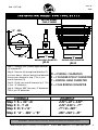
1
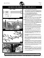
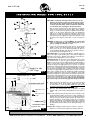
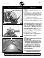
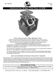
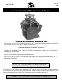
No.1177-IS
Rev D
4/05
Instruction Sheet For Tool #1177
TWIN CAM “Alpha” & “Beta” Case Boring Tool
The JIMS® Twin Cam Case Boring Tool takes all the guess work out of boring Twin Cam engine cases to accept JIMS® 4" bore cylinders,
100” big bore kit, and 113" and 116" flywheel stroker kits. Will also work on cylinders up 4.125” with stock cylinder stud pattern. This
tool is designed to be used in a heavy-duty 15" drill press, or milling machine.
Note: Please read all instructions completely and thoroughly before performing any work.
IF YOU DO NOT KNOW WHAT YOU ARE DOING, DO NOT DO IT!
None of the information in this instruction sheet pertaining to motorcycle repair is represented as fool-proof or even
altogether safe. Some people can ruin a mechanic’s vise with a tack hammer. Even something safe, done incorrectly or
incompletly can and will backfire.
You and only you are responsible for the safety of your repair work and for your understanding and application with
the use of repair equipment, components, methods and concepts.
Each and every step that this tool is designed to do must be carefully and systematically performed safely by you. All
®
information listed in this instruction sheet has been tested, re-tested and used daily in JIMS Research and
Developement Department.
JIMS® IS NOT RESPONSIBLE FOR THE QUALITY AND SAFETY OF YOUR WORK.
Tools required for boring:
1/8”, 3/16", 1/4", & 5/16" Allen wrenches, 7/16” Wrench, Calipers, Torque
wrench, 1/2" socket, Cutting Fluid, Drill press or Milling machine.
Follow instructions in H-D® Service Manual for removal of engine for your year and model. With engine removed from frame and safely mounted in one of JIMS® Twin Cam motor stands (refer to JIMS® catalog for stands), follow the engine disassembly instructions in
the service manual, including removing and installing cylinder studs. Mask off all bearings and oil holes to prevent chips from contaminating those areas. Bolt cases together with HD® hardware using sequence and torque specs stated in H-D® service manual, except top
center case bolt between cylinders. Install this bolt last and torque to 50-90 in-lbs. maximum (Read Step 1).
CAUTION:
Wear safety glasses. Excessive force may damage parts!
555 Dawson Drive, Camarillo, CA 93012
Phone 805-482-6913 • Fax 805-482-7422
1
No.1177-IS
Rev D
4/05
Instruction Sheet For Tool #1177
INSTRUCTIONS
FOR 4” BORE
1A. 4” BORE INFORMATION BEFORE STARTING:
Prior to boring your case, you must modify your top center
5/16” case bolt that is located between the spigot holes as
shown in FIG. 3 (see arrow). You need to modify the 5/16”
case bolt as shown in Fig. 1A for 4” bore. NOTE: Failure to do
so will result in damage to the cutting tool.
+/- .010
+/- .010
+/- .010
Fig.1A
FOR 4 1/8” BORE
1B. 4-1/8” BORE INFORMATION BEFORE STARTING:
Prior to boring your case you must decide on how to obtain
the proper clearance for your top center case bolt as shown
in Fig. 3. (See arrow). NOTE: Failure to do so will result in
damage to the cutting tool.
(1B) Option 1. You may use the stock case bolt and modify the
case bolt diameter similar to the bolt shown in Fig. 1A. NOTE:
Failure to do so will result in damage to the cutting tool.
(1B) Option 2. You may use a 5/16” x 5” long stud or allen bolt with
nuts and washers. You may drill a 5/16” hole through the right
case with normal bolt clearance. You should spot face the right
side case hole as shown in Fig. 1B to maintain flatness. You will
need to provide more clearance for the 5/16” allen bolt or stud
similar to 4” bore bolt as shown in Fig. 1A. NOTE: Failure to do
so will result in damage to the cutting tool.
Fig.1B
Fig.1C
(1B) Option 3. You may use a 1/4” x 5” long stud or an allen bolt,
both with nuts and washers. Drill 1/4” hole with normal clearance through the right side of the case. You should spot face
the hole as shown in Fig. 1B to maintain flatness. You will then
need to check your allen or stud bolt for the proper clearance
and it may need to be modified to be similar to the bolt as
shown in Fig. 1A. NOTE: Failure to do so will result in damage to the cutting tool.
2.
Assemble Engine Cradle (No.1, No.2 & No.3) with all nine
3/8” allen screws as shown in Fig.2. Torque the nine 3/8”
allen screws to 10 ft. lbs. Make sure all mating surfaces are
clean. Position Plate (No.3) with the appropriate lettering
"A" for Alpha, "B" for Beta, facing
outboard. NOTE: Lube all
hardware with 20w50 H.D.® oil.
3.
Place the Engine Case in the Cradle and rotate the case so
either the Front or Rear cylinder deck is horizontal and facing up. Fig.3
4.
Install (2) lubed 1/4-20 SHCS (No.10) into the holes marked
with "F" or "R", depending on the spigot bore you are modifying, in the plate No.3 as shown in Fig.2. Do not tighten.
Install (3) lubed 5/16-18 SHCS (No.13) into plate (No.1)
holes marked with letter of the spigot bore you are modifying. Do not tighten.
5.
Install lubed "T" Pin (No.14) into hole in (No.3), as shown in
Fig.2 & Fig.4, marked "F" for Front or "R" for Rear depending
on which spigot bore you are modifying. This will align the
spigot bore perpendicularly to the machine spindle. You may
need to rotate the case slightly to get the "T" Pin to locate
properly in the hole. Using a 3/16” allen wrench, torque the
1/4-20 SHCS (No.10) to 90-120 in-lbs. and all 5/16-18 SHCS
(No.9) to 13-15 ft-lbs using a 1/4” allen wrench.
6.
INSTALLING CUTTERS:
Note: Boring Head set-up shown is for reference only. Your
set-up will vary depending on cylinder bore and cylinder
manufacturer. Instruction sheet is written for boring clearance for 4” bore cylinders. Again, if your cylinders are from
a different manufacturer or you are machining for other than
a 4” bore, you will need to calculate your cutter dimensions
(see set-up sheet on page 5).
MODEL TYPE FACING OUT
14
3
10
13
22
2
9
11
11
9
1
Fig.2
Fig.3
CAUTION:
Fig.4
Wear safety glasses. Excessive force may damage parts!
555 Dawson Drive, Camarillo, CA 93012
Phone 805-482-6913 • Fax 805-482-7422
2
No.1177-IS
Rev D
4/05
Instruction Sheet For Tool #1177
20
NOTE: JIMS® recommends removing no more that .125” (on the
diameter) of material at a time. Case machining may require
more than one pass and more than one set-up of the cutters
to obtain your desired bore. Failure to follow this could result
in a ruff finish, and /or damage to the bore and cutters.
17
18
12
12
19
Once you have determineed the cutter dimensions, install the
cutters in the boring head as shown in Fig. 5. Fig. 6, & Fig. 7.
Using a 1/8” Allen wrench, adjust the adjustment screws (No.
1689) to set the cutters dimensions from your calculations
(Fig. 7). Use a caliper for accurate measurements. Ensure that
the cutters are held snug against the adjusting screws as the
lock down screws are tightened. Torque the lock down screws
(In order shown, Fig. 7) to 90 in./lbs, to secure the cutters in
place.
6
17
7
4
15
WARNING: If cutters are set beyond O4.40, the cutters may
come in contact with the I.D. of the locating plate (1177-5
[No.5]), voiding the warranty of 1177-5.
15
16
7.
21
8
9
9
5
Fig.5
Spigot Depth Note: If using other than JIMS® 4” cylinders add .03”.06" to the length of your cylinder spigot. This will be the depth you
need to bore your cases to. (Example: If your spigot is 1.600" add .03”.06" and your bore depth will be 1.630" +.03/-.00).
Rough Cut Side
(.03” Step) Fig.6
Alignment Pin Note: On the bottom of the support plate (No.5) there
are machined reliefs to clear the opposite cylinder’s alignment pin
(Fig.8). In some motor cases the alignment pins are installed higher or
lower, so you will need to check to make sure that they do not interfere
with the mounting of the support plate (No.5) to the case. To check the
alignment pin clearance, place the Boring Head Assembly on case with
a 1-1/2" to 2" wood block between boring assembly plates to prevent
the top plate from dropping, and or resulting in the cutter contacting
your case (See Fig.9). Without tightening the two screws (No.1668),
place a piece of paper between the neighboring cylinder’s alignment
pin and the support plate. Once you have torqued the screws make
sure that the paper moves freely between the alignment pin and the
support plate. If the alignment pin is too high (the paper will not move)
the pin can be installed deeper or removed. If the pin is damaged during removal it will need to be replaced. Failure to check the alignment
pin clearance may result in the final spigot bore being out of center.
Finish Cut Side
Dimensions for 4” Bore
1st
Using a 1/8” allen wrench and a 7/16” wrench, set the boring
depth to 1.850 +.03/-.00 by adjusting the stop depth adjustment screw (No.18) on the Boring Assembly top plate as
shown in Fig.5 & Fig.8, measured from the finish tool cutter to
the bottom of the locating plate (No.5).
nd
2nd
2
8.
Finish Cut Side
Rough Cut Side
2nd
1st
st
21nd
Tighten these screws
first.
2nd
Tighten these screws
second.
LOCK DOWN SCREWS
2 PLC No.1689
Fig.7
CAUTION:
9.
Mount the Boring Assembly onto motor case with (2) lubed
3/8-16 SHCS (No.9) using cylinder alignment pins (HD®
No.16595-99A) to locate assembly. Make sure the Boring
Assembly is sitting flush on the motor case. Using a 5/16” allen
wrench torque the mounting bolts to 18-20 ft-lbs.
Place the Case Boring Fixture onto a drill press or milling
machine table. Center shaft of Boring Head (No.4) in chuck or
collet.
Note: If using a chuck, be sure the chuck jaws locate on the flats on the
boring head shaft. Tighten the chuck (or collet depending on
machine being used), and remove the wood block. Clamp the
base (No.2) to the drill press table using the provided holes if
possible. If unable to use provided holes be sure to clamp the
fixture using C-Clamps or comparable clamps. Before running
machine, lube the two guide dowels with a light oil and run
the quill up and down to make sure the Boring Assembly is not
binding.
Caution: When checking to make sure the tool action is correct, be
aware not to strike the cutters against the crankcase while the
Wear safety glasses. Excessive force may damage parts!
555 Dawson Drive, Camarillo, CA 93012
Phone 805-482-6913 • Fax 805-482-7422
3
No.1177-IS
Rev D
4/05
Instruction Sheet For Tool #1177
Cylinder Dowel Reliefs
Depth adjustment screw
machine is not running. Damage may result to the tool and the
crankcase.
Note: If the base plate assembly is not sitting flat to the press table,
adjust the table (or head) flat before clamping down the tool
assembly.
10. Set the machine’s speed to approximately 600-800 RPM’s.
Before running the machine, make sure the quill is at the top of
its travel. Start the machine to make sure head or table are not
vibrating. If no vibrations, the RPM’s can be increased. If vibrations occur RPM’s will need to be reduced. JIMS® has found that
600-800 RPM is best when using a drill press, although results
may vary.
Caution: Always wear safety glasses!
11. Start boring with a slow, even pressure while applying cutting
fluid (Slower feed rate will yield a cleaner finish) until the Boring
Assembly Stop bottoms out. Shut down the machine and wait
until it comes to a complete stop. Slowly retract the boring
assembly untill it clears the case. Replace the wood block, and
remove the Boring Assembly from the case.
Fig.8
Note: Place a 1-1/2" to 2" wood block between boring
assembly plates to keep top plate from dropping.
CAUTION: It is recommended that you use a well maintained
and dependable machine for this type of work. If you use a drill
press or milling machine that is not up to normal standards,
you take the chance of damage to your work and/or injury to
yourself. This is why we recommend you use a safe and well
maintaned drill press or milling machine. Make sure your
machine is in good working order before starting any project.
ALWAYS WEAR SAFETY GLASSES OR OTHER FACE AND EYE
PROTECTION SUCH AS FULL FACE SHIELD.
12. Remove (2) 1/4-20 SHCS (No.10), (3) 5/16-18 SHCS (No.13),
and "T" Pin (No.14). Rotate case so opposite spigot bore is
straight up and repeat steps 3-11.
13. Wash cases as needed to remove all chips.
Fig.9
CAUTION: Be sure to remove any case material from the top
center case bolt holes of both left and right cases that are not
attached well enough to stay in place during motor operation.
See Fig.10 and Fig.1C (Fig. 1C on page 2.)
NOTE: This is mostly a judgment call as to how much material will be
removed.
DO NOT REMOVE ANY MORE MATERIAL THEN NEEDED FOR A
SAFE RUNNING MOTOR.
NOTE: When re-assembling cases, tighten case bolts to factory
specs except top center case bolt between cylinders. Tighten
this bolt last after you have cylinders and heads installed and
torqued to H.D.® specs. Apply Hylomar, or equivalent, sealer to
shoulder of top center case bolt and torque to 50-90 in-lbs.
maximum on 1/4” or 5/16” center bolt stud.
CAUTION: BEFORE RE-ASSEMBLY OF YOUR ENGINE MAKE
SURE THE THE INSIDE OF THE CASE, SPIGOT BORE AND ALL
INTERIOR AND EXTERIOR POCKETS AND HOLES ARE FREE
FROM ANY CONTAMINANTS. STOP, DOUBLE CHECK AND
THEN TRIPLE CHECK. YOU DO NOT WANT ANY CONTAMINANTS LEFT INSIDE. DOING SO CAN AND WILL CAUSE PREMATURE WEAR AND DAMAGE.
Fig.10
CAUTION:
JIMS® IS NOT RESPONSIBLE FOR YOUR WORK!
SO PLEASE USE YOUR BEST JUDGEMENT AND ALWAYS DOUBLE
AND EVEN TRIPLE CHECK YOUR WORK. DOING SO WILL HELP
ENSURE A POSITIVE EXPERIENCE AND OUTCOME.
Wear safety glasses. Excessive force may damage parts!
555 Dawson Drive, Camarillo, CA 93012
Phone 805-482-6913 • Fax 805-482-7422
4
No.1177-IS
Rev D
4/05
Instruction Sheet For Tool #1177
SET-UP SHEET
FOR 4” BORE
“A” .385
FINISH
U.S.A.
ROUGH
U.S.A.
X
R
XX
#1177-4
“T”
“S”
BORING HEAD DIAMETER
BORING HEAD DIAMETER
.320 “B”
O3.45
O4.20
Step 1: Measure your cylinder spigot diameter.
(S) and add .02”.
Step 2: Measure the boring head diameter (T)
as shown above. Subtract boring head diameter
from answer obtained in step 1, this is your
overall clearance (D).
Step 3: Divide your overall clearance by 2. This
is your “A” dimension.
D = OVERALL CLEARANCE
S = CYLINDER SPIGOT DIAMETER
T = BORING HEAD DIAMETER
C = CASE BORING DIAMETER
Step 4: Subtract .065” from your “A” dimension.
This is you “B” dimension.
FORMULA
Step 1: S + .02” =C
Step 2: C - T =D
Step 3: D / 2 =”A”
Step 4: “A” - .065” = ”B”
CAUTION:
EXAMPLE
4.20”+.02”= 4.22”
4.22”-3.45”= .77”
.77”/ 2= .385”
.385”-.065”= .32”
Wear safety glasses. Excessive force may damage parts!
555 Dawson Drive, Camarillo, CA 93012
Phone 805-482-6913 • Fax 805-482-7422
5
No.1177-IS
Rev D
4/05
Instruction Sheet For Tool #1177
PARTS LIST
NO.
QTY
1
2
3
4
5
6
7
8
9
10
11
12
13
14
15
16
17
18
19
20
21
22
23
1
1
1
1
1
1
1
1
9
2
4
2
3
1
2
6
2
1
1
1
1
3
1
TITLE OR DESCRIPTION
PART NUMBER
MOUNTING PLATE
BASE PLATE
ALIGNMENT PLATE
BORING HEAD, BORING ASSEMBLY
LOCATING PLATE, BORING ASSEMBLY
SUPPORT PLATE, BORING ASSEMBLY
SHIELDED BEARING
PULL OUT DOWEL
3/8-16 x 1” SHCS
1/4-20 x 1” SHCS
DOWEL PIN, 1/4” x 3/4”
BUSHING
5/16-18 x 1” SHCS
T-PIN, O 3/8” SHANK
TOOL BIT, AL, CEMENTED CARBIDE, 3/8”
1/4-28 x 1/2”, set screw
WASHER, 1/4”, SAE
1/4-20 x 1-3/4” Set Screw
1/4-20 JAM NUT
1/4-20 x1/2”, BHCS
DOWEL PIN, 1/2” x 3-1/2”
3/8” AN WASHER
INSTRUCTION SHEET
1177-1
1177-2
1177-3
1177-4
1177-5*
1177-6
8149
1685
1686
2133
8093
1681
2405
1687
1688 **
1689
1683
1679
1682
8090
1680
1265
1177-IS
*1175-5 is not covered under warranty if locating plate displays cutter marks from improper adjustment.
** 1688 Non-serviceable wear item, no warranty.
WARRANTY
All JIMS® parts are guaranteed to the original purchaser to be free of manufacturing defects in material and workmanship for a period
of six (6) months from the date of purchase. Merchandise that fails to conform to these conditions will be repaired or replaced at JIMS® option
the parts are returned within the six (6) months warranty period or within ten (10) Days thereafter.
In the event warranty service is required, the original purchaser must call or write JIMS® immediately with the problem. Some problems
can be rectified by a telephone call and need no further course of action. A part suspected of being defected must not be replaced by a dealer
without prior authorization by JIMS®. If it is deemed necessary for JIMS® to make an evaluation to determine whether the part is defective, it
must be packaged properly to prevent further damage and be returned prepaid to JIMS® with a copy of the original invoice of purchase and a
detailed letter outlining the nature of the problem, how the part was used and the circumstances at the time of failure. If after an evaluation has
been made by JIMS® and the part was found to be defective, repair, replacement or credit will be granted.
1.
2.
3.
4.
5.
ADDITIONAL WARRANTY PROVISIONS
JIMS® shall have no obligation in the event a JIMS® part is modified by person or organization.
JIMS® shall have no obligation if a JIMS® part becomes defective in whole or in part as a result of improper installation, improper
maintenance, improper use, abnormal operation, or any other misuse or mistreatment of the part.
JIMS® shall not be liable for any consequential or incidental damages resulting in the failure of a JIMS® part, the breach of any
warranties, the failure to deliver, delay in delivery, delivery in nonconforming condition, or for any other breach of contract or
duty between JIMS® and a customer.
JIMS® parts are designed exclusively for use in Harley-Davidson® motorcycles. JIMS® shall have no warranty or liability obligation if JIMS® part is used
in any other application.
Any parts or tool replaced by JIMS® becomes the property of JIMS® and will not be returned under any circumstance.
555 Dawson Drive, Camarillo, CA 93012
Phone 805-482-6913 • Fax 805-482-7422
6