1
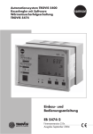
Automation System 5400
Boiler Controller
TROVIS 5474
Mounting and
Operating Instructions
EB 5474 EN
®
Electronics from SAMSON
Firmware version 2.0x
Edition July 2004
Disclaimer of liability
Disclaimer of liability
We are constantly developing our products and therefore, reserve the right to change the product or the information contained in this document at any time without notice.
We do not assume any liability for the accuracy or completeness of these mounting and
operating instructions. Moreover, we do not guarantee that the buyer can use the product for an
intended purpose. SAMSON rejects any liability for claims by the buyer, especially claims for
compensation including lost profits or any other financial loss, except the damage was caused
intentionally or by gross negligence. If an essential term of the contract is breached by
negligence, SAMSON’s liability is limited to the foreseeable damage.
Safety instructions
4 The device may only be assembled, started up or operated by trained and
experienced personnel familiar with the product. Proper shipping and
appropriate storage are assumed.
4 The controller has been designed for use in electrical power systems. For
4
2
EB 5474 EN
wiring and maintenance, you are required to observe the relevant safety
regulations.
The Safety shutdown function (section 8.10) does not replace the safety temperature limiter as the boiler controller is not a safety-relevant component.
Contents
Contents
1
1.1
1.1.1
1.1.2
1.2
1.3
1.4
1.5
1.6
1.6.1
1.6.2
Operation . . . . . . . . . . . . . . . . . . . . . . . . . . . . . . . 6
Operating elements . . . . . . . . . . . . . . . . . . . . . . . . . . . 6
Operating keys . . . . . . . . . . . . . . . . . . . . . . . . . . . . . 6
Operating switches . . . . . . . . . . . . . . . . . . . . . . . . . . . 7
Operating modes . . . . . . . . . . . . . . . . . . . . . . . . . . . . 8
Display. . . . . . . . . . . . . . . . . . . . . . . . . . . . . . . . . 9
Displaying data . . . . . . . . . . . . . . . . . . . . . . . . . . . . 10
Setting the controller time . . . . . . . . . . . . . . . . . . . . . . . 11
Setting the times-of-use . . . . . . . . . . . . . . . . . . . . . . . . 13
Entering vacation periods . . . . . . . . . . . . . . . . . . . . . . . 15
Entering public holidays . . . . . . . . . . . . . . . . . . . . . . . . 16
2
2.1
2.2
2.3
2.4
2.5
2.6
Start-up. . . . . . . . . . . . . . . . . . . . . .
Setting the system code number and the boiler rating
Activating and deactivating functions. . . . . . . .
Changing parameters . . . . . . . . . . . . . . .
Enter key number . . . . . . . . . . . . . . . . .
Calibrating sensors . . . . . . . . . . . . . . . .
Resetting to default values . . . . . . . . . . . . .
3
Manual operation . . . . . . . . . . . . . . . . . . . . . . . . . . . 25
4
Systems. . . . . . . . . . . . . . . . . . . . . . . . . . . . . . . . 26
5
5.1
5.2
5.2.1
5.2.2
5.2.3
5.2.4
5.2.5
5.3
5.3.1
5.3.2
5.3.3
5.3.4
5.4
5.4.1
5.5
Boiler functions . . . . . . . . . . . . . . . . . . .
Boiler switching behavior . . . . . . . . . . . . . .
Lag/lead sequence control. . . . . . . . . . . . . .
Control without sensor VFg . . . . . . . . . . . . .
Outdoor temperature-dependent sequence . . . . . .
Capacity-dependent sequence . . . . . . . . . . . .
Sequence lock. . . . . . . . . . . . . . . . . . . .
Lag delay . . . . . . . . . . . . . . . . . . . . . .
Change in lag/lead sequence (Anl 4 to 7) . . . . . .
Outdoor temperature-dependent change (Anl 5 and 7)
Capacity-dependent change (Anl 5 and 7) . . . . . .
Operating hours-dependent change (Anl 5 and 7) . .
Change with binary input (Anl 4 to 7) . . . . . . . .
Return flow boost . . . . . . . . . . . . . . . . . .
Common return flow boost . . . . . . . . . . . . .
Parallel operation (Anl 7) . . . . . . . . . . . . . .
.
.
.
.
.
.
.
.
.
.
.
.
.
.
.
.
.
.
.
.
.
.
.
.
.
.
.
.
.
.
.
.
.
.
.
.
.
.
.
.
.
.
.
.
.
.
.
.
.
.
.
.
.
.
.
.
.
.
.
.
.
.
.
.
.
.
.
.
.
.
.
.
.
.
.
.
.
.
.
.
.
.
.
.
.
.
.
.
.
.
.
.
.
.
.
.
.
.
.
.
.
.
.
.
.
.
.
.
.
.
.
.
.
.
.
.
.
.
.
.
.
.
.
.
.
.
.
.
.
.
.
.
.
.
.
.
.
.
.
.
.
.
.
.
.
.
.
.
.
.
.
.
.
.
.
.
.
.
.
.
.
.
.
.
.
.
.
.
.
.
.
.
.
.
.
.
.
.
.
.
.
.
.
.
.
.
.
.
.
.
.
.
.
.
.
.
.
.
.
.
.
.
.
.
.
.
.
.
.
.
.
.
.
.
EB 5474 EN
18
18
19
21
22
22
24
32
32
34
34
34
35
35
35
36
36
36
37
37
37
38
38
3
Contents
5.6
5.7
5.8
5.9
5.10
5.11
Operating hours counter. . . . . . . . .
Boiler pump control . . . . . . . . . . .
Boiler sensor acting as a thermostat . . .
Modulation feedback . . . . . . . . . .
Operational alarm . . . . . . . . . . .
Return flow sensor acting as a thermostat .
6
6.1
6.2
Functions of the heating circuit . . . . . . . . . . . . . . . . . . . . 42
Outdoor temperature-dependent advance heating . . . . . . . . . . . 42
Optimization using a room sensor . . . . . . . . . . . . . . . . . . . 42
7
7.1
7.1.1
7.2
7.3
7.4
Functions of the DHW circuit. . . . . . . . . . . . .
DHW heating in the storage tank system (Anl 1 to 3) .
Priority circuit (Anl 1 to 3) . . . . . . . . . . . . . .
Forced charging of the DHW storage tank (Anl 1 to 7)
Thermal disinfection (Anl 1 to 3) . . . . . . . . . . .
External DHW demand (Anl 1 to 7) . . . . . . . . .
.
.
.
.
.
.
.
.
.
.
.
.
.
.
.
.
.
.
.
.
.
.
.
.
.
.
.
.
.
.
44
44
45
46
47
48
8
8.1
8.1.1
8.1.2
8.2
8.3
8.4
8.5
8.6
8.7
8.8
8.9
8.10
8.11
8.11.1
8.11.2
8.11.3
8.12
8.13
8.14
8.15
System-wide functions . . . . . . . . . . . . . . . . . . . .
Weather-compensated control . . . . . . . . . . . . . . . . .
Gradient characteristic . . . . . . . . . . . . . . . . . . . .
4-point characteristic . . . . . . . . . . . . . . . . . . . . .
Fixed set point control . . . . . . . . . . . . . . . . . . . . .
Differential temperature control using variable weighting factors .
Deactivation depending on outdoor temperature . . . . . . . .
Summer mode. . . . . . . . . . . . . . . . . . . . . . . . .
Delayed outdoor temperature adaptation . . . . . . . . . . . .
Automatic summer time/winter time changeover . . . . . . . .
Frost protection . . . . . . . . . . . . . . . . . . . . . . . .
Forced operation of the pumps . . . . . . . . . . . . . . . . .
Flow temperature limitation . . . . . . . . . . . . . . . . . .
Control mode . . . . . . . . . . . . . . . . . . . . . . . . .
Three-step control . . . . . . . . . . . . . . . . . . . . . . .
On/off control . . . . . . . . . . . . . . . . . . . . . . . .
Continuous control . . . . . . . . . . . . . . . . . . . . . .
Control signal deactivation. . . . . . . . . . . . . . . . . . .
Processing of external demand. . . . . . . . . . . . . . . . .
Feedforwarding the outdoor temperature . . . . . . . . . . . .
Locking of changed settings . . . . . . . . . . . . . . . . . .
.
.
.
.
.
.
.
.
.
.
.
.
.
.
.
.
.
.
.
.
.
.
.
.
.
.
.
.
.
.
.
.
.
.
.
.
.
.
.
.
.
.
.
.
.
.
.
.
.
.
.
.
.
.
.
.
.
.
.
.
.
.
.
.
.
.
.
.
.
.
.
.
.
.
.
.
.
.
.
.
.
.
.
.
49
49
50
51
52
53
53
54
54
55
55
56
56
57
58
58
58
59
59
59
60
9
Operational faults . . . . . . . . . . . . . . . . . . . . . . . . . . 61
4
EB 5474 EN
.
.
.
.
.
.
.
.
.
.
.
.
.
.
.
.
.
.
.
.
.
.
.
.
.
.
.
.
.
.
.
.
.
.
.
.
.
.
.
.
.
.
.
.
.
.
.
.
.
.
.
.
.
.
.
.
.
.
.
.
.
.
.
.
.
.
.
.
.
.
.
.
.
.
.
.
.
.
.
.
.
.
.
.
.
.
.
.
.
.
.
.
.
.
.
.
.
.
.
.
.
.
.
.
.
.
.
.
.
.
.
.
.
.
38
39
39
40
40
41
Contents
9.1
9.2
9.3
9.4
9.5
9.5.1
9.5.2
Error list . . . . . . . . . . . . . . . .
Sensor failure . . . . . . . . . . . . . .
Displaying the lead/collective error alarm
Error status register . . . . . . . . . . .
Error alarms . . . . . . . . . . . . . .
Sending text message in case of error . .
Sending fax in case of a fault alarm . . .
.
.
.
.
.
.
.
.
.
.
.
.
.
.
.
.
.
.
.
.
.
.
.
.
.
.
.
.
.
.
.
.
.
.
.
.
.
.
.
.
.
.
.
.
.
.
.
.
.
.
.
.
.
.
.
.
.
.
.
.
.
.
.
.
.
.
.
.
.
.
.
.
.
.
.
.
.
.
.
.
.
.
.
.
.
.
.
.
.
.
.
.
.
.
.
.
.
.
.
.
.
.
.
.
.
61
61
62
62
64
64
65
10
10.1
10.2
10.3
10.4
10.4.1
10.5
Communication . . . . . . . . . . . . . . . . . . . .
Controller with RS-232 port . . . . . . . . . . . . . .
System bus interface in conjunction with cable converters
RS-232/RS-485 (for four-wire bus) . . . . . . . . . .
Description of communication parameters to be adjusted
Meter bus interface . . . . . . . . . . . . . . . . . .
Activating the meter bus . . . . . . . . . . . . . . . .
Memory module. . . . . . . . . . . . . . . . . . . .
11
Installation . . . . . . . . . . . . . . . . . . . . . . . . . . . . . . 74
12
Electrical connection. . . . . . . . . . . . . . . . . . . . . . . . . . 76
13
13.1
13.2
13.3
13.4
13.5
13.6
Appendix . . . . . . . . . . . . . . . . . . . . . . . . . . . . . . . 82
Function block list . . . . . . . . . . . . . . . . . . . . . . . . . . . 82
Parameter lists . . . . . . . . . . . . . . . . . . . . . . . . . . . . 93
Displays . . . . . . . . . . . . . . . . . . . . . . . . . . . . . . . 107
Sensor resistance tables . . . . . . . . . . . . . . . . . . . . . . . 115
Technical data . . . . . . . . . . . . . . . . . . . . . . . . . . . . 116
Customer data . . . . . . . . . . . . . . . . . . . . . . . . . . . . 117
Index . . . . . . . . . . . . . . . . . . . . . . . . . . . . . . . . 125
. . . . . . . . 66
. . . . . . . . 67
.
.
.
.
.
.
.
.
.
.
.
.
.
.
.
.
.
.
.
.
.
.
.
.
.
.
.
.
.
.
.
.
.
.
.
.
.
.
.
.
EB 5474 EN
68
69
71
71
73
5
Operation
1
Operation
The controller is ready for use with the temperatures and time schedules preset by the manufacturer.
On start-up, the current time and date need to be set at the controller (–> section 1.5).
1.1
Operating elements
The operating controls are located in the front panel of the controller and protected by a Plexiglas door.
1.1.1 Operating keys
Changeover key
(press using a pointed object such as a pen)
Switch from the info level to the parameter and configuration level and back
Reset key
(press using a pointed object such as a pen)
Press to reset accessible parameters to their default settings; the controller
must be in the configuration level
Arrow keys
– To scroll within levels
– To change values
Enter key
– To access levels
– Access parameters and functions to edit them
– Confirm settings
– Display set points in the info level
6
EB 5474 EN
Operation
1.1.2 Operating switches
Mode selector switch
Automatic mode with switchover between
day mode and night mode
Automatic mode with switchover between
day mode and stand-by mode
Day mode (rated operation)
Night mode (reduced operation)
Manual/maintenance mode
Stand-by mode
Selector switch
Boiler 1 and 2 in operation;
automatic lag/lead sequence change
Boiler 1 in operation,
Boiler 2 switched off
Boiler 2 in operation,
Boiler 1 switched off
Boiler 1 and 2 switched off
Boiler 1 and 2 in operation;
Boiler 2 as lead boiler
1 2 1 2 O 1 21 2
Boiler 1 and 2 in operation;
Boiler 1 as lead boiler
EB 5474 EN
7
Operation
Correction switch for the flow temperature
Set point set-back by 2.5 °C per notch
No change in set point
Set point raised by 2.5 °C per notch
0
1.2
+
Operating modes
Day mode (rated operation)
Regardless of the programmed times-of-use and summer mode, the set points relevant for rated
operation are used by the controller.
Night mode (reduced operation)
Regardless of the programmed times-of-use and summer mode, the set points relevant for reduced operation are used by the controller.
Stand-by mode
The controller is switched off. The boilers only work when there is a demand for DHW or a demand for an external set point. The protective functions remain active.
Automatic mode
During the programmed times-of-use, the controller works in rated operation. Outside these
times-of-use, the controller is in reduced operation or stand-by mode, depending on the settings. The controller switches automatically between both operating modes.
Maintenance mode
Pumps are controlled manually (–> section 3).
Control is not possible. Use the maintenance mode just for maintenance purposes and for emission measurements.
The default setting of the circulation pumps is set for constant operation.
8
EB 5474 EN
Operation
1.3
Display
During operation, the display indicates the current time as well as information about the operation of the controller. The times-of-use are represented by black squares below the row of numbers at the top of the display. Icons indicate the operating status of the controller.
0 1 2 3 4 5 6 7 8 910 11 12 13141516171819202122 2324
1
2
3
4
5
6
7
8
1
1
9
2
2
10
1 Automatic operation
2
1
1
2
11
12
13
14
15
2 Rated operation
8 Manual/maintenance
mode
3 Vacation mode
9 Malfunction
13 Valve in control circuit 2
Open: Left arrow
Closed: Right arrow
4 Reduced operation
10 Boiler and boiler stages
14 Boiler pump 2 ON
5 Public holiday mode
11 Valve in control circuit 1
Open: Left arrow
Closed: Right arrow
15 DHW heating
6 Summer mode
7 Frost protection
12 Boiler pump 1 ON
Fig. 1 · Icons
The controller status can be displayed in the operating level (–> section 1.4).
EB 5474 EN
9
Operation
1.4
Displaying data
Controller time, measured values, set points and limits, times-of-use, public holidays and vacation periods can be retrieved and displayed in the InF1 to InF9 info levels (-> Fig. 10 on page
131). The various levels are listed in section 13.3.
4 InF1: Boiler 1
4 InF2: System Anl 1 to 3, Co5 -> Fb13 = ON: Separate heating circuit
System Anl 4 to 7: Boiler 2
4 InF3: System Anl 1 to 3, Co5 -> Fb13 = ON: Direct heating circuit
4 InF4: DHW heating
4 InF5: General information, e.g. times-of-use
4 InF8: Error initialization
4 InF9: Modbus and meter bus communication
Proceed as follows:
Select info level.
Open info level.
Scroll to read the various datapoints of the selected info level that appear one after
the other.
Compare the set point/limit with the actual value.
Press both arrows keys simultaneously:
Return to the display with time.
10
EB 5474 EN
Operation
1.5
Setting the controller time
The current time and date need to be set immediately after start-up and after a power failure
lasting longer than 24 hours. This is indicated by the time blinking on the display.
The time is set in the PA5 parameter level.
Proceed as follows:
0 1 2 3 4 5 6 7 8 9 10 11 12 13 14 15 16 17 18 19 20 21 22 23 24
Switch to the configuration and parameter level.
Display: PA1
0 1 2 3 4 5 6 7 8 9 10 11 12 13 14 15 16 17 18 19 20 21 22 23 24
Select PA5 parameter level.
1
0 1 2 3 4 5 6 7 8 9 10 11 12 13 14 15 16 17 18 19 20 21 22 23 24
Open PA5 parameter level.
Display: Time
Activate editing mode for the controller time.
blinks.
Change time.
0 1 2 3 4 5 6 7 8 9 10 11 12 13 14 15 16 17 18 19 20 21 22 23 24
Confirm time.
Display: Date (Day-Month)
Activate editing mode for the date.
blinks.
Change date.
EB 5474 EN
11
Operation
0 1 2 3 4 5 6 7 8 9 10 11 12 13 14 15 16 17 18 19 20 21 22 23 24
Confirm date.
Display: Year
Activate editing mode for the controller time.
blinks.
Change year.
Confirm year.
Exit PA5 parameter level.
Return to the operating level.
Note!
The controller automatically returns to the operating level if the keys are left unpressed for two
minutes.
12
EB 5474 EN
Operation
1.6
Setting the times-of-use
Two times-of-use can be set for each day of the week. If only one time-of-use is required, the
start and stop times of the second time-of-use must be programmed to identical times.
Parameters
WE
Period/day
1–7
Parameter level / Range of values
PA5 / 1–7, 1 to 7
Start first time-of-use
7:00
PA5 / 00:00 to 24:00h; in steps of 30 minutes
Stop first time-of-use
12:00
PA5 / 00:00 to 24:00h; in steps of 30 minutes
Start second time-of-use
12:00
PA5 / 00:00 to 24:00h; in steps of 30 minutes
Stop second time-of-use
22:00
PA5 / 00:00 to 24:00h; in steps of 30 minutes
Proceed as follows:
0 1 2 3 4 5 6 7 8 9 10 11 12 13 14 15 16 17 18 19 20 21 22 23 24
Switch to the configuration and parameter level.
Display: PA1
Select PA5 parameter level.
Open PA5 parameter level.
Display: Controller time
0 1 2 3 4 5 6 7 8 9 10 11 12 13 14 15 16 17 18 19 20 21 22 23 24
Select datapoint for times-of-use.
Display:
1
0 1 2 3 4 5 6 7 8 9 10 11 12 13 14 15 16 17 18 19 20 21 22 23 24
Activate editing mode for times-of-use.
Display: 1–7
Select period/day for which the times-of-use are to be
valid:
1–7 = Monday to Sunday,
1 = Monday, 2 = Tuesday, …, 7 = Sunday
EB 5474 EN
13
Operation
0 1 2 3 4 5 6 7 8 9 10 11 12 13 14 15 16 17 18 19 20 21 22 23 24
START
Activate editing mode for period/day.
Display: START;
blinks.
Edit start time (steps of 30 minutes).
0 1 2 3 4 5 6 7 8 9 10 11 12 13 14 15 16 17 18 19 20 21 22 23 24
STOP
Confirm start time.
Display: STOP
Edit stop time (steps of 30 minutes).
Confirm stop time.
Display: START
The second time-of-use is set like the first time-of-use.
To set the times-of-use for each day, repeat the instructions in the fields highlighted in gray.
Select End on the display.
Exit the datapoint for times-of-use.
Exit the parameter level.
Return to the operating level.
Note!
Do not use the 1–7 menu to check the programmed times-of-use. On opening this menu, the times-of-use are reset to their default settings.
Note!
The controller automatically returns to the operating level if the keys are left unpressed for two
minutes.
14
EB 5474 EN
Operation
1.6.1 Entering vacation periods
When the switch position Automatic operation with switchover between day mode and night
mode is selected, night set points (reduced set points) are used by the controller. When the
switch position Automatic operation with switchover between day mode and stand-by mode
is selected, the system is switched off. The frost protection function remains active.
A maximum of 10 vacation periods may be entered.
Parameter
WE
Parameter level / Range of value
Vacation periods
–
PA5 / 01.01 to 31.12
Proceed as follows:
Switch to the parameter and configuration level.
Display: PA1
Select PA5 parameter level.
Open PA5 parameter level. Display: Controller time
0 1 2 3 4 5 6 7 8 9 10 11 12 13 14 15 16 17 18 19 20 21 22 23 24
Select datapoint for vacation period. Display:
Open data point for vacation period. Display: START
If applicable, select – – – –.
Activate editing mode for vacation periods.
blinks.
Set start date of vacation period.
Confirm start date of the vacation period.
Display: STOP
Set end of vacation period.
Confirm end of the vacation period.
To enter additional vacations, re-select – – – – (between 31.12 and 01.01) and repeat the steps
in the fields highlighted in gray.
Exit the parameter level.
Return to the operating level.
Note!
In systems Anl 1 to 3 with integrated DHW heating (Co5 -> Fb13 = ON), the vacations entered
also apply to the DHW heating with the setting Co4 -> Fb10 = ON.
EB 5474 EN
15
Operation
Vacation periods that are not assigned to a specific date should be deleted by the end of the
year so that they are not carried on into the following year.
Deleting vacation periods:
Select the vacation period you wish to delete in the datapoint for vacation periods.
Confirm selection.
Select – – – – .
Delete vacation period.
Note!
The controller automatically returns to the operating level if the keys are left unpressed for two
minutes.
1.6.2 Entering public holidays
The times-of-use programmed for Sunday apply on public holidays. A maximum of 20 public
holidays can be entered.
Parameter
WE
Parameter level / Range of value
Public holidays
–
PA5 / 01.01 to 31.12
Proceed as follows:
Switch to the parameter and configuration level.
Display: PA1
Select PA5 parameter level.
Open PA5 parameter level. Display: Controller time
0 1 2 3 4 5 6 7 8 9 10 11 12 13141516171819202122 2324
Select datapoint for public holidays.
Display:
Open datapoint for public holidays.
Display: START
If applicable, select – – – –.
Activate editing mode for public holiday.
blinks.
Edit public holiday.
Confirm public holiday.
16
EB 5474 EN
Operation
To enter additional public holidays, re-select – – – – (between 31.12 and 01.01) and repeat the
steps in the fields highlighted in gray.
Exit the parameter level.
Return to the operating level.
Note!
In systems Anl 1 to 3 with integrated DHW heating (Co5 -> Fb13 = ON), the public holidays entered also apply to the DHW heating with the setting Co4 -> Fb10 = ON.
Public holidays that are not assigned to a specific date should be deleted by the end of the year
so that they are not carried on into the following year.
Deleting a public holiday:
Select the holiday you wish to delete in the datapoint for public holidays.
Confirm selection.
Select – – – – .
Delete the public holiday.
Note!
The controller automatically returns to the operating level if the keys are left unpressed for two
minutes.
EB 5474 EN
17
Start-up
2
Start-up
2.1
Setting the system code number and the boiler rating
7 different hydraulic schematics are available. Each system configuration is represented by a
system code number (Anl). The different schematics are dealt with in section 4. Available controller functions are described in sections 5 to 8.
Changing the system code number resets previously adjusted function blocks to their default settings (WE). Function block parameters and settings in the parameter level remain unchanged.
The system code number is set in the parameter and configuration level.
Proceed as follows:
Switch to the parameter and configuration level.
Display shows: PA1
Select Anl level.
Open Anl level.
1
Anl 1
Display:
Select system code number (Anl).
System Anl 1
1
Anl 1
Single boiler for one-stage burner
System Anl 2
1
2
Anl 2
Single boiler for two-stage burner
System Anl 3
1
2
Anl 3
Single boiler for modulating burner
1
Anl 4
Double boiler for one-stage condensing boiler and
two-stage low-temperature boiler
System Anl 4
System Anl 5
System Anl 6
System Anl 7
1
2
1
2
1
2
1
2
Anl 5
1
2
1
2
Anl 6
1
2
1
2
Anl 7
Double boiler for 2 two-stage burners
Double boiler for modulating and two-stage burner
Double boiler for two modulating burners
Confirm system code number (Anl).
The burner and stage icons for burner 1 blink.
The boiler rating is shown.
18
EB 5474 EN
Start-up
Set the required rating.
Set first the capacity of the basic stage and then the total capacity of the burner of
two-stage and modulating burners.
Confirm the rating.
Set the capacity of the second burner in systems Anl 4 to 7.
Select End on the display.
Exit the Anl level.
Display: Co1
2.2
Activating and deactivating functions
A function is activated or deactivated in the associated function block. The numbers 0 to 24 in
the top row of the display represent the respective function block numbers. When a configuration level is opened, the activated function blocks are indicated by a black square on the
right-hand side below the function block number. The function blocks are described in section 13.2.
The functions are arranged in topic groups:
4 Co1: Boiler 1
4 Co2: Systems Anl 1 to 3, Co5 -> Fb13 = ON: separate heating circuit
Systems Anl 4 to 7: Boiler 2
4 Co3: Systems Anl 1 to 3, Co5 -> Fb13 = ON: direct heating circuit
4 Co4: DHW heating
4 Co5: General functions
4 Co6: Sensor initialization
4 Co8: Error initialization
4 Co9: Modbus and meter bus communication
Proceed as follows:
Switch to the parameter and configuration level.
Display shows: PA1
Switch to the configuration level (-> Fig. 10, page 131).
Open the configuration level.
EB 5474 EN
19
Start-up
Select function block.
Activate editing mode for function block.
The function block number starts to blink.
If 0 0 0 0 appears on the display, the key number needs to be entered first (refer to
section 2.4).
Activate function block (Fb = ON).
An activated function block is indicated by a black square below (right) the function
block number in the top row of the controller display.
or:
Deactivate function block (Fb = OFF).
Confirm setting.
If the function block is not closed, further function block parameters can be adjusted.
Proceed as follows:
Make the desired changes and confirm.
If applicable, the next function block parameter is displayed.
Confirm all parameters to exit the opened function block.
To adjust additional function blocks within the configuration level, repeat the steps in the fields
highlighted in gray.
Exit the configuration level.
Return to the operating level.
Note!
The controller automatically returns to the operating level if the keys are left unpressed for two
minutes.
20
EB 5474 EN
Start-up
2.3
Changing parameters
Depending on the activated functions, not all parameters listed in the parameter list in the Appendix (–> section 13.2) might be available.
The parameters are arranged in topic groups:
4 PA1: Boiler 1
4 PA2: Systems Anl 1 to 3, Co5 -> Fb13 = ON: separate heating circuit
Systems Anl 4 to 7: Boiler 2
4 PA3: Systems Anl 1 to 3, Co5 -> Fb13 = ON: direct heating circuit
4 PA4: DHW heating
4 PA5: General parameters
4 PA9: Modbus and meter bus communication
Proceed as follows:
Switch to the parameter and configuration level. Display: PA1
Select parameter level (-> Fig. 10, page 131).
Open the parameter level.
Select parameter.
Activate editing mode for parameter.
Change parameter.
Confirm parameter setting.
To adjust additional parameters, repeat the steps in the fields highlighted in gray.
Exit the parameter level.
Return to the operating level.
Note!
The controller automatically returns to the operating level if the keys are left unpressed for two
minutes.
EB 5474 EN
21
Start-up
2.4
Enter key number
Some functions are protected against unintentional or unauthorized access. These functions can
only be activated or deactivated after the valid key number has been entered. The valid key
number for initial start-up can be found on page 127. To avoid unauthorized use of the key
number, remove the page or make the key number unreadable.
Proceed as follows:
0 0 0 0 blinks on the display.
Set valid key number.
Confirm key number.
When the correct key number is entered, the function block to be changed blinks on the
display.
When an incorrect key number is entered, the controller returns to the next configuration
level.
The key number remains active for approx. 10 minutes.
2.5
Calibrating sensors
The connected sensors are calibrated in the Co6 configuration level. The following applies:
4 Co6 -> Fb00 = ON:
4 Co6 -> Fb00 = OFF:
Pt 100/Pt 1000 sensors mixed (default setting)
Pt 100/PTC sensors mixed
The resistance values of the sensors can be found on page 115.
Each universal input can be configured separately.
The function block parameter includes the following types: Ni 200/1000, PTC, NTC,
Pt 100/1000, (0/4 to 20) mA. The function blocks Co6 -> Fb01 to Fb17 correspond to the binary inputs BE1 to BE17 in the terminal wiring plan (–> page 78 onwards).
Activate the function block for the required sensor and select the function block parameter
which matches the type of the input signal.
Note!
Pt 100 or Pt 1000 sensor should be used to measure the flow temperature as only these types of
sensor are able to measure temperatures reaching up to 160 °C (maximum temperature of the
flow temperature set point).
22
EB 5474 EN
Start-up
If the temperature values displayed at the controller differ from the actual temperatures, the
measured values of all connected sensors can be changed or readjusted. To calibrate a sensor,
the currently displayed sensor value must be changed such that it matches the temperature (reference temperature) measured directly at the point of measurement.
Perform the calibration in function block Fb23 in Co6.
Proceed as follows:
Switch to the parameter and configuration level.
Display: PA1
Select Co6 configuration level.
Open Co6 configuration level.
Select function block Fb23.
Confirm setting.
Display: 0 0 0 0
Enter currently valid key number.
The function block Fb23 blinks on the display.
Activate function block.
Confirm setting.
Select the function block for the sensor to be calibrated:
The function blocks Co6 -> Fb01 to Fb17 correspond to the binary inputs BE1 to BE17
in the terminal wiring plan (–> page 78 onwards) depending on the selected system
code number (Anl), e.g. Co6 -> Fb03 for sensor VFg (all systems).
Activate editing mode for sensor.
Fb_ blinks on the display.
Display measured temperature.
Activate editing mode for measured temperature.
Measured temperature blinks.
Correct measured temperature.
Read the actual temperature directly from the thermometer at the point of measurement and enter this value as the reference temperature.
Confirm corrected measured temperature.
Additional sensors are calibrated similarly.
EB 5474 EN
23
Start-up
Select function block Fb23.
Activate editing mode for function block Fb23.
Deactivate function block Fb23.
Confirm setting.
Select End on the display.
Exit the configuration level.
Return to the operating level.
Note!
The adjusted sensor values are not reset by the function for resetting to default values.
2.6
Resetting to default values
All parameters and function blocks that can be set without entering the key number can be reset
to their default settings (WE).
Proceed as follows:
Reset to default settings.
Function blocks and parameters are reset to their default settings (WE).
Note!
Resetting protected parameters to their default settings is only possible when the key number is
still active.
The controller is ready for operation with its default settings. You just need to set the correct date
and current time.
24
EB 5474 EN
Manual operation
3
Manual operation
All the settings of the outputs can be set in the manual mode, see wiring plan (-> section 12).
Proceed as follows:
Set mode selector switch to
.
After approx. 10 seconds the boilers start operation at
full capacity. Display:
Select HAnd on the display.
0 1 2 3 4 5 6 7 8 9 10 11 12 13 14 15 16 17 18 19 20 21 22 23 24
Open the manual level. Display: bA1
1
Select output:
bA: 1, 2
3-Pt: 1, 2
PU: 1, 2
StUF: 1, 2, 3, 4
AnAL: 1, 2
BA1 and BA2
BA3 and BA4, BA5 and BA6
BA7 and BA8
BA9 to BA12
AA 1, 2 (RK1, RK2)
Activate editing mode for output.
The display blinks.
Activate output, increase value.
Three-point stepping output: OPEN
or:
Deactivate output, decrease value.
Three-point stepping output: CLOSED
and:
Three-point stepping output: STOP
Confirm setting.
The changed values remain valid as long as the manual
mode is active.
Slide mode switch to
.
Exit the manual level.
Note!
In manual mode, frost protection does not function.
EB 5474 EN
25
Systems
4
Systems
7 hydraulic schematics are available.
System code
System description
number (Anl)
26
Comments
1
Single boiler for one-stage burner
2
Single boiler for two-stage burner
3
Single boiler for modulating burner
4
Double boiler for one-stage condensing boiler
and two-stage low-temperature boiler
Lag sequence without automatic
lag/lead sequence change
5
Double boiler for 2 two-stage burners
Change in lag/lead sequence either
depending on operating hours, on
outdoor temperature or boiler
capacity
6
Double boiler for modulating und
two-stage burners
Lag sequence without automatic
lag/lead sequence change
7
Double boiler for two modulating
burners
Change in lag/lead sequence either
depending on operating hours, on
outdoor temperature or boiler
capacity
EB 5474 EN
Optionally separate heating circuit
and DHW heating can be controlled
Systems
System Anl 1 with Co5 -> Fb13 = OFF
VFg
AF
VL
RüFg
RL
RK1
KF1
Pu1
RüF1
1
K1 One-stage burner
System Anl 1 with Co5 -> Fb13 = ON
RF
VF2
AF
RüF2
Pu2
Pu3
VFg
RK2
RK1 RüFg
KF1
Pu1
SLP
RüF1
1
SF1
SF2
K1 One-stage burner
EB 5474 EN
27
Systems
System Anl 2 with Co5 -> Fb13 = OFF
VFg
AF
VL
RüFg
RL
RK1
KF1
Pu1
RüF1
K1 Two-stage burner
1
2
System Anl 2 with Co5 -> Fb13 = ON
RF
VF2
AF
RüF2
Pu2
Pu3
VFg
RK2
RK1 RüFg
KF1
Pu1
SLP
RüF1
1
2
SF1
SF2
K1 Two-stage burner
28
EB 5474 EN
Systems
System Anl 3 with Co5 -> Fb13 = OFF
VFg
AF
VL
RüFg
RL
RK1
KF1
Pu1
RüF1
K1 Modulating burner
System Anl 3 with Co5 -> Fb13 = ON
RF
VF2
AF
RüF2
Pu2
Pu3
VFg
RK2
RK1 RüFg
KF1
Pu1
SLP
RüF1
SF1
SF2
K1 Modulating burner
EB 5474 EN
29
Systems
System Anl 4
VFg
VL
RL
RüFg
RK1
KF1
1
Pu1
RüF1
AF
RK2
KF2
1
2
Pu2
RüF2
K1 One-stage condensing boiler
K2 Two-stage low-temperature boiler
System Anl 5
VFg
VL
RüFg
RK1
KF1
1
2
30
EB 5474 EN
Pu1
RüF1
RL
RK2
KF2
1
2
Pu2
RüF2
K1, K2 Two-stage burner
AF
Systems
System Anl 6
VFg
VL
RL
RüFg
RK1
KF1
Pu1
AF
RK2
KF2
Pu2
K1 Modulating burner
RüF1
1
2
K2 Two-stage burner
RüF2
System Anl 7
VFg
VL
RüFg
RK1
KF1
Pu1
RüF1
AF
RL
RK2
KF2
Pu2
RüF2
K1, K2 Modulating burner
EB 5474 EN
31
Boiler functions
5
Boiler functions
5.1
Boiler switching behavior
The Minimum activation and deactivation time parameters have priority over all other parameters described in following.
To be able to keep the cooling off periods between two activation phases, a boiler is first
switched on when the time entered in Minimum deactivation time has passed since the last deactivation.
To ensure the burning of residues left over during the start-up phase, a boiler is switched off first
after the time entered in Minimum activation time has elapsed.
Parameters
WE
Parameter level / Range of values
Minimum activation time
1 min
PA1, PA2* / 0 to 90 min
Minimum deactivation time
2 min
PA1, PA2* / 0 to 90 min
* Only in systems Anl 4 to 7
On/off boiler
A boiler is activated when the flow temperature falls below the flow temperature set point by
the Hysteresis (Fig. 3). After the operational feedback message (burner firing –> section 5.10),
the Lockout time must elapse before the boiler is switched to the next stage. If the flow temperature is expected to reach the set point range within the Tolerance time, the boiler does not switch
to the next stage.
A boiler stage is switched off when the flow temperature exceeds the flow temperature set point
by the Hysteresis.
Modulating boiler
A boiler starts to operate with its minimum capacity if the flow temperature falls below the flow
temperature set point by the Hysteresis (Fig. 2). After the operational feedback message (burner
firing –> section 5.10), the Lockout time must elapse before the modulation is enabled. The controller modulates the boiler capacity to match the actual energy requirement according to the
flow temperature set point.
Parameters
WE
Parameter level / Range of values
Hysteresis
3 °C
PA5 / 1 to 20 °C
Tolerance time
30 min PA5 / 0 to 99 min
Lockout time
2 min
32
EB 5474 EN
PA5 / 0 to 99 min
Boiler functions
tVL [°C]
Flow temperature set point +
Hysteresis
Flow temperature set point
t [s]
Flow temperature set point –
Hysteresis
Lockout time
Burner start
Tolerance time
Operational alarm
f. burner
Activation of
boiler stage
Fig. 3 · Criteria for switching the boiler stages
tVL [°C]
Flow temperature set point +
Hysteresis
t [s]
Flow temperature set point
Flow temperature set point –
Hysteresis
Lockout time
Burner start
Tolerance time
Activation of
boiler stage
Operational alarm
f. burner
Fig. 2 · Criteria for switching the modulating boiler
EB 5474 EN
33
Boiler functions
5.2
Lag/lead sequence control
The boilers are released depending on the configuration:
4 Co1, Co2* -> Fb00 = OFF: Boiler released according to the position of the mode selector
switch
4 Co1, Co2* -> Fb00 = ON: Boiler 1 is not released if binary input BE17 is closed, provided Boiler 1 is not locked by the mode switch.
Boiler 2* is released if binary input BE16 is closed, provided Boiler 2 is not locked by the
mode switch.
Function
WE
Configuration
Release of boiler K1, 2
OFF
Co1, Co2* -> Fb00
* Only in systems Anl 4 to 7
5.2.1 Control without sensor VFg
The Burner activation independent from sensor VFg function allows the boiler to be switched
on independently from sensor VFg, i.e. exclusively according to boiler sensors VF1 and VF2.
Other functions which have an effect on the lag and lead sequence control of the boiler in
two-boiler systems do not affect the boiler which works independently any more.
On activating the Continuous running of pump function, the boiler pumps react like the pumps
of master controller in normal systems.
Functions
WE
Configuration
Burner activation not dependent on
sensor VFg
OFF
Co5 -> Fb20 = ON
Continuous running of pump
OFF
Co5 -> Fb14
5.2.2 Outdoor temperature-dependent sequence
If the outdoor temperature is above the limit entered in Temperature tA for releasing sequence,
just the lead boiler always remains in operation. The lag boiler is not even activated when the
maximum capacity of the lead boiler is insufficient to achieve an increased flow temperature.
The lag boiler is first released when the outdoor temperature is lower than the limit entered in
Temperature tA for releasing sequence after t = 2 x Lockout time.
The limit entered in Temperature tA for releasing sequence must be selected to ensure that a
short-term demand above the limit can be compensated for without any loss in comfort by prolonging the operating time of the lead boiler. This depends on the performance of the lead
boiler.
34
EB 5474 EN
Boiler functions
Function
WE
Configuration
Releasing sequence
ON
Co5 -> Fb07 = ON
Parameters
WE
Parameter level / Range of values
Lockout time
2 min
PA5 / 0 to 99 min
Temperature tA for releasing sequence
12 °C
PA5 / –40 to 50 °C
5.2.3 Capacity-dependent sequence
The lead boiler is activated when the flow temperature falls below the flow temperature set point
by the Hysteresis. In the event of a demand for increased capacity, the lead boiler switches to
the second stage. The second boiler is also activated if 90 % of its maximum load is not sufficient
over the time period of t = 2 x Lockout time to increase the flow temperature to the required flow
temperature set point and the set point hysteresis is not reached within the tolerance time.
The lag boiler is switched off when one of the following conditions is fulfilled:
The current load of both boilers is less than 90 %.
The actual temperature is greater than the set point and hysteresis added together as well as
its tendency shows that the temperature will not fall below this total within the tolerance time.
4
4
Function
WE
Configuration
Releasing sequence
ON
Co5 -> Fb07 = OFF
Parameter
WE
Parameter level / Range of values
Lockout time
2 min
PA5 / 0 to 99 min
5.2.4 Sequence lock
The binary input BE11 is used to lock the sequence. The input of the outdoor temperature is determined by the binary input. The outdoor sensor is not required.
Function
WE
Configuration
Outdoor sensor
ON
Co5 -> Fb00 = OFF, select: FoAUS
5.2.5 Lag delay
The Lag delay parameter helps minimize losses during start-up in the event of short-term demands. The second boiler is first switched on when required after the time in Lag delay has
elapsed. The time countdown is shown in the InF5 level.
EB 5474 EN
35
Boiler functions
Parameter
WE
Lag delay
10 min PA5 / 0 to 90 min
5.3
Parameter level / Range of values
Change in lag/lead sequence (Anl 4 to 7)
The lag/lead sequence can be changed depending on the outdoor temperature, operating
hours or capacity. The change in lag/lead sequence is only effective when the mode selector
switch is set to 1 2 and with the configuration Co5 -> Fb20 = OFF.
Note!
A change in lag/lead always takes place when the controller detects a fault in the lead boiler
regardless of the configuration.
5.3.1 Outdoor temperature-dependent change (Anl 5 and 7)
The outdoor temperature-dependent change in lag/lead sequence is only appropriate when
boilers with varying capacity are used.
The lead boiler is determined by comparing the mean outdoor temperature over three days with
the Reverse sequence limit tA parameter:
4 Outdoor temperature > Outdoor temperature limit for lag/lead sequence change: Lead
boiler is the boiler with the smallest unit capacity
4 Outdoor temperature < Outdoor temperature limit for lag/lead sequence change: Lead
boiler is the boiler with the largest unit capacity
WE
Configuration
Automatic change in lag/lead sequence
ON
Co5 -> Fb09 = ON
Condition for change in lag/lead sequence
ON
Co5 -> Fb10 = OFF, select: 1
Parameter
WE
Parameter level / Range of values
Outdoor temperature limit for lag/lead
sequence change
15 °C
PA5 / –40 to 50 °C
Functions
5.3.2 Capacity-dependent change (Anl 5 and 7)
The lead boiler is the boiler which had the lowest average capacity over the past three days.
Functions
WE
Configuration
Automatic change in lag/lead sequence
ON
Co5 -> Fb09 = ON
36
EB 5474 EN
Boiler functions
Condition for change in lag/lead sequence
ON
Co5 -> Fb10 = OFF, select: 2
5.3.3 Operating hours-dependent change (Anl 5 and 7)
After a fixed amount of time has elapsed, counting in hours from the time when the last lag/lead
sequence took place (Time interval for lag/lead sequence change), the other boiler takes on the
role as lead boiler.
The elapsed operating hours since the last change in lag/lead sequence are shown in the InF5
level.
Functions
WE
Configuration
Automatic change in lag/lead sequence
ON
Co5 -> Fb09 = ON
Condition for change in lag/lead sequence
ON
Co5 -> Fb10 = ON
Parameter
WE
Parameter level / Range of values
Time interval for lag/lead sequence change
168 h
PA5 / 1 to 999 h
5.3.4 Change with binary input (Anl 4 to 7)
The binary input BE4 can be used for the change in lag/lead sequence when the DHW heating
is not being controlled:
BE4 = OFF: Boiler 1 as lead boiler
BE4 = ON: Boiler 2 as lead boiler
4
4
Functions
WE
Configuration
DHW demand – active
ON
Co4 -> Fb00 = OFF
Automatic change in lag/lead sequence
OFF
Co5 -> Fb09 = OFF
Note!
In system Anl 7 the binary input BE4 can be used either for modulation feedback, for an external demand for DHW or for an external change in lag/lead sequence.
5.4
Return flow boost
On fulfilling the criteria for activation (–> section 5.1) the return flow control circuit is closed at
the valve RK1/RK2. In the released boiler K1/K2 (see above), the first stage of the boiler and
the boiler pump Pu1/Pu2 is switched on. The water is circulated in the boiler circuit.
The return control circuit is released if the temperature at the sensor RüF1/RüF2 exceeds the
limit entered in Minimum return flow temperature. The mixing valve opens and release the cor-
EB 5474 EN
37
Boiler functions
responding flow rate to the plant until the valve is completely opened and the boiler pump delivers the maximum flow rate in the plant.
Parameter
WE
Parameter level / Range of values
Minimum return flow temperature
50 °C
PA1, PA2* / 20 to 120 °C
* Only in systems Anl 4 to 7
Depending on the configuration, the return flow boost can be controlled with a continuous
signal, on/off signal or three-point stepping signal (–> section 8.11).
5.4.1 Common return flow boost
In systems with two boilers (systems Anl 4, 5, 6 and 7), a common return flow boost can be implemented. This is done by using the return flow control circuit of the first boiler K1, depending
on whether the boiler is in operation.
Function
WE
Configuration
Common return flow boost
OFF
Co5 -> Fb12 = ON
5.5
Parallel operation (Anl 7)
This function leads to both boilers working constantly in parallel (no lag/lead sequence
control).
The boilers start operating one after the other, taking into account the programmed times: Minimum deactivation time for boiler K1, 2 and Lag delay as well as taking into account Temperature tA for releasing sequence
Function
WE
Configuration
Parallel operation of boilers
OFF
Co5 -> Fb19 = ON
Parameters
WE
Parameter level / Range of values
Minimum deactivation time f. boiler K1, 2
0 min
PA1, 2 / 0 to 90 min
Lag delay
10 min PA5 / 0 to 90 min
Temperature tA for releasing sequence
12 °C
5.6
PA5 / –40 to 50 °C
Operating hours counter
This function allows the performed operating hours of boilers K1, 2 to be shown in the Inf1, 2
levels. The control is not affected by the counted operating hours. If the operating hours should
be selected to start at a certain initial value, this can be programmed separately.
38
EB 5474 EN
Boiler functions
Function
WE
Operating hours counter
OFF
Configuration
Co1, Co2* -> Fb02 = ON
0h
Initial value / Configurable as required
count Counting the operating hours
rESEt Reset operating hours to initial value
* Only in systems Anl 4 to 7
5.7
Boiler pump control
The boiler pump control is connected with the boiler control loop.
When a boiler is switched on to the first stage, the associated boiler pump is also switched on.
When the boiler is switched off, the boiler is switched off too either after the Pump lag time has
elapsed or when the temperature falls below Boiler flow limit.
In summer mode, the boiler pump is switched off together with the boiler when the deactivation
criteria are fulfilled.
In systems without hydraulic separator, in which the heating water must be circulated through
the boiler, the boiler pump may not be switched off. For this purpose, the Continuous running of
pump function is activated. The boiler pump continues to run when the lead boiler is switched
off and the valve is opened. As a result, the cold system water can reach the boiler return flow
pipe. If the return flow temperature is a factor that needs to be monitored in the boiler, the installation of an hydraulic separator is recommended.
Function
WE
Configuration
Continuous running of pump
OFF
Co5 -> Fb14 = ON
5 min
55 °C
Pump lag time / 0 to 90 min
Boiler flow limit / 20 to 120 °C
5.8
Boiler sensor acting as a thermostat
The boiler sensors KF1 and KF2 control the safety deactivation (–> section 8.10), which is triggered whenever the maximum flow temperature is exceeded, as well as the temperature-dependent pump lag of the boiler pumps Pu1 and Pu2 (–> section 5.7).
The maximum permissible flow temperature can also be monitored in systems Anl 4, 5 and 6
with thermostats. The inputs of the boiler sensors must be defined as binary inputs for this purpose. The thermostats are connected to the same terminals as the boiler sensors.
EB 5474 EN
39
Boiler functions
Function
WE
Configuration
Boiler sensor KF1, 2
ON
Co1, Co2* -> Fb03 = OFF
StEiG: Thermostat closes
FALL: Thermostat opens
*Only in systems Anl 4 to 7
5.9
Modulation feedback
The modulation feedback in systems Anl 3, 6 and 7 can be implemented by a potentiometer (1
to 2 kΩ) or by a limit switch for maximum boiler capacity output.
Modulation feedback with potentiometer
The inputs for the potentiometer are marked in the wiring diagrams (–> section 12) with SG_K1
(potentiometer 1) and with SG_K2 (potentiometer 2).
Function
WE
Configuration
Modulation feedback K1, 2
ON
Co1, Co2* -> Fb07 = ON
* Only in system Anl 7
Note!
In system Anl 7, the binary input BE4 can be used either for modulation feedback, for external
DHW demand or for external change in lag/lead sequence.
5.10 Operational alarm
The boiler controller waits for an operational alarm before it continues (–> section 5.1). The
operational alarm can optionally be issued over a binary input or after fixed time entered in
Start-up time for boiler parameter.
40
EB 5474 EN
Boiler functions
Operational alarm over a binary input
The inputs for the operational alarm are marked in the wiring diagrams (section 12) with BE2
BM_K1 for Boiler 1 and with BE1 BM_K2 for Boiler 2.
Function
WE
Configuration
Operational alarm K1, 2
ON
Co1, Co2* -> Fb01 = ON
* Only in systems Anl 4 to 7
Operational alarm after start-up
Function
WE
Configuration
Operational alarm K1, 2
ON
Co1, Co2* -> Fb01 = OFF
0s
Start-up time for boiler / 0 to 5400 s
* Only in systems Anl 4 to 7
5.11 Return flow sensor acting as a thermostat
The return flow sensors can optionally be replaced by thermostats. For this purpose, the inputs
for the return flow sensors are defined as binary inputs. The thermostats are connected to the
same terminals as the return flow sensors.
Function
WE
Configuration
Return flow sensor RüF1, 2
ON
Co1, Co2* -> Fb04 = OFF
StEiG: Thermostat closes
FALL: Thermostat opens
* Only in systems Anl 4 to 7
EB 5474 EN
41
Functions of the heating circuit
6
Functions of the heating circuit
6.1
Outdoor temperature-dependent advance heating
Only selectable for systems Anl 1 to 3 with Co5 -> Fb13 = ON.
The controller switches the heating on before the time-of-use starts in normal operation depending on the outdoor temperature. The Advance heating time is based on an outdoor temperature
of –12 °C. The advance heating time is shortened in case of higher outdoor temperatures.
Functions
WE
Configuration
Heating circuit with DHW heating
OFF
Co5 -> Fb13 = ON
Optimization
OFF
120 min
Co3 -> Fb05 = ON, select: 1
Advance heating time / 0 to 360 min
ON
Co5 -> Fb00 = ON
Outdoor sensor
6.2
Optimization using a room sensor
Only selectable for systems Anl 1 to 3 with Co5 -> Fb13 = ON.
Both the functions described should only be used if the room in which the room sensor is located
(reference room) has a heating characteristic that is similar to the rest of the building.
No thermostat valves should be mounted on the radiators in the reference room.
There are two types of optimization depending on the activation conditions:
4 Outdoor temperature-dependent advance heating, room temperature-dependent deacti-
4
vation
The controller activates the heating depending on the outdoor temperature before the
time-of-use starts in normal operation. The Advance heating time is based on an outdoor
temperature of –12 °C. The advance heating time is shorter when the outdoor temperature is
higher (see section 6.1).
Room temperature-dependent advance heating and deactivation
The controller calculates the required advance heating time (max. 6 hours) adapted to the
building characteristics, resulting in the Day set point (rated room temperature) being
reached in the reference room when the time-of-use starts. The heating is heated with the
maximum flow temperature during the advance heating phase. As soon as the Day set point
is reached, outdoor temperature-dependent control starts.
The controller deactivates the heating in both types of optimization depending on the room sensors up to two hours before the time-of-use finishes.
The controller chooses the deactivation time such in a way that the room temperature does not
drop significantly below the desired temperature until the time-of-use ends.
42
EB 5474 EN
Functions of the heating circuit
Outside the times-of-use, the controller monitors the Night set point (reduced room temperature)
or the Sustained temperature in the case of room temperature-dependent deactivation. When
the temperature falls below the night set point, the controller heats with the max. flow temperature until the measured room temperature exceeds the adjusted value by 1 °C.
Note!
Direct sunshine can cause the room temperature to increase and thus result in the premature deactivation of the heating system.
A drop in room temperature within a brief period outside of the time-of-use may lead to the advance heating to reach the room temperature being activated too early.
Functions
WE
Configuration
Heating circuit with DHW heating
OFF
Co5 -> Fb13 = ON
Room sensor
OFF
Co3 -> Fb00 = ON
Outdoor temperature-dependent advance heating, room temperature-dependent deactivation:
Optimization
OFF
Outdoor sensor AF1 to 3
ON
Co3 -> Fb05 = ON, select: 2
120 min Advance heating time / 0 to 360 min
Co5 -> Fb00 = ON
Room temperature-dependent advance heating and deactivation:
Optimization
OFF
Co3 -> Fb05 = ON, select: 3
Parameter
WE
Parameter level / Range of values
Day set point
20 °C
PA3 / 10 to 40 °C
Night set point
17 °C
PA3 / 10 to 40 °C
Sustained temperature
10 °C
PA3 / 10 to 40 °C
EB 5474 EN
43
Functions of the DHW circuit
7
Functions of the DHW circuit
Only systems Anl 1 to 3 have their own DHW heating (DHW heating in storage system with
Co5 -> Fb13 = ON).
The systems Anl 4 to 7 do not have their own DHW heating; they are, however, able to process
an external DHW demand (-> section 7.4) and to reduce an excessively high flow temperature
over a DHW forced charging in the external system (-> section 7.2).
7.1
DHW heating in the storage tank system (Anl 1 to 3)
WW
SLP
SF1
SF2
ZP
KW
SLP
Storage tank charging pump
SF1
Storage tank sensor 1
SF2
Storage tank sensor 2
ZP
Circulation pump
WW
Hot water
KW
Cold water
Fig. 4 · DHW heating in a storage tank system
Operation with storage tank sensor SF1
The controller begins charging the storage tank when the water temperature measured at sensor SF1 falls below the set point DHW demand ON. The controller stops charging the storage
tank when the water temperature in the storage tank measured at sensor SF1 reaches the value
T = DHW demand ON + Hysteresis.
The set point Boiler set point for DHW demand determines the set point at sensor VFg.
Functions
WE
Configuration
Heating circuit with DHW heating
OFF
Co5 -> Fb13 = ON
Storage tank sensor SF1
OFF
Co4 -> Fb03 = ON
Storage tank sensor SF2
OFF
Co4 -> Fb04 = OFF
Parameters
WE
Parameter level / Range of values
Boiler set point for DHW demand
65 °C
PA4 / 20 to 120 °C
DHW demand ON
40 °C
PA4 / 20 to 90 °C
5 °C
PA4 / 0 to 30 °C
Hysteresis
44
EB 5474 EN
Functions of the DHW circuit
Operation with two storage tank sensors SF1 and SF2
The controller begins charging the storage tank when the water temperature measured at sensor SF1 falls below the set point DHW demand ON. The controller stops charging the storage
tank when the water temperature in the storage tank measured at sensor SF2 reaches the value
DHW demand OFF.
The set point Boiler set point for DHW demand determines the set point at sensor VFg.
Functions
WE
Configuration
Heating circuit with DHW heating
OFF
Co5 -> Fb13 = ON
Storage tank sensor SF1
OFF
Co4 -> Fb03 = ON
Storage tank sensor SF2
OFF
Co4 -> Fb04 = ON
Parameters
WE
Parameter level / Range of values
Boiler set point for DHW demand
65 °C
PA4 / 20 to 120 °C
DHW demand ON
40 °C
PA4 / 20 to 90 °C
DHW demand OFF
45 °C
PA4 / 20 to 90 °C
Operation with storage tank thermostat
The storage tank thermostat is connected to SF1 and switches the storage tank charging on and
off. The set point Boiler set point for DHW demand must still be predetermined.
Functions
WE
Configuration
Heating circuit with DHW heating
OFF
Co4 -> Fb13 = ON
Storage tank sensor SF1
OFF
Co4 -> Fb03 = OFF
Storage tank sensor SF2
OFF
Co4 -> Fb04 = OFF
Parameter
WE
Parameter level / Range of values
Boiler set point for DHW demand
65 °C
PA4 / 20 to 120 °C
7.1.1 Priority circuit (Anl 1 to 3)
The DHW heating can be switched with priority over the separate heating circuit 2 or directly
over the heating circuit (heating circuit 3, Pu3).
Heating circuit 2:
During the storage tank charging, the separate heating circuit 2 is placed in reduced operation.
EB 5474 EN
45
Functions of the DHW circuit
Functions
WE
Configuration
Heating circuit with DHW heating
OFF
Co5 -> Fb13 = ON
DHW priority over HK2
OFF
Co4 -> Fb06 = ON
Heating circuit 3:
During the storage tank charging, the direct heating circuit is switched off. The separate heating
circuit runs in parallel.
Functions
WE
Configuration
Heating circuit with DHW heating
OFF
Co5 -> Fb13 = ON
DHW priority over HK3
OFF
Co4 -> Fb07 = ON
Note!
When the DHW priority over HK3 function is deactivated, the direct heating circuit also runs in
parallel to the DHW charging. The heating circuit may, however, only be overheated by 10 °C .
In other words, the heating circuit is supplied with not enough heat when the boiler set point for
the heating circuit is greater than Boiler set point for DHW demand. The heating circuit is switched
off during storage tank charging when the Boiler set point for DHW demand is 10 °C higher than
the boiler set point.
7.2
Forced charging of the DHW storage tank (Anl 1 to 7)
A forced charging of the DHW storage tank can prevent that the safety equipment place the
boiler out of operation in case of excessively high flow temperature.
The forced charging of the DHW storage tank takes place when the Maximum limit for DHW
forced charging is exceeded at the flow sensor together with sensor VFg or at one of the two
boiler sensors KF1 or KF2.
In systems without their own DHW heating (systems Anl 4 to 7) the demand for a forced charging is passed on to the connected controllers at binary output BA1. The actual forced charging is
started by the controllers that are responsible for the DHW heating.
Functions
WE
Configuration
Heating circuit with DHW heating
OFF
Co5 -> Fb13 = ON*
Forced charging of DHW storage
tank
OFF
Co4 -> Fb02 = ON
80 °C
Maximum limit f. DHW forced charging/20 to 120 °C
* Not in systems Anl 4 to 7
46
EB 5474 EN
Functions of the DHW circuit
7.3
Thermal disinfection (Anl 1 to 3)
In all systems with DHW heating, the DHW storage tank is thermally disinfected on the selected
Day of week or daily. The storage tank is heated up to the adjusted Disinfection temperature.
The charging temperature is always 5 °C higher than the Disinfection temperature.
Thermal disinfection starts at the adjusted Start time and finishes at the Stop time at the latest. If
blinks on the
the Disinfection temperature is not reached at the end of thermal disinfection,
display. The error alarm is automatically reset when the Disinfection temperature is reached
during the next thermal disinfection.
Thermal disinfection for preventing legionella infection causes
4 high return flow temperatures during the disinfection cycle (return flow temperature limitation suspended),
4 high storage tank temperatures after thermal disinfection has been concluded,
4 lime scale (possibly), which can have a negative effect on heat exchanger performance.
Note!
This function is not available when a storage tank thermostat is used.
Functions
WE
Configuration
Heating circuit with DHW heating
OFF
Co5 -> Fb13 = ON
Storage tank sensor SF1
OFF
Co5 -> Fb03 = ON
Thermal disinfection
OFF
Co4 -> Fb08 = ON
3
70 °C
00:00
04:00
Day of week / 0, 1 to 7 (daily, Mon to Sun)
Disinfection temperature / 50 to 80 °C
Start time / 00:00 to 23:59 h
Stop time / 00:00 to 23:59 h
EB 5474 EN
47
Functions of the DHW circuit
7.4
External DHW demand (Anl 1 to 7)
This function allows the boiler controller to switch over to the Boiler set point for DHW demand
when the binary input BE4 (WWA) is closed. The thermal disinfection has priority when the external DHW demand and thermal disinfection coincide.
Functions
WE
Configuration
Modulation feedback K2
ON
Co2 -> Fb07 = OFF
DHW demand – active
ON
Co4 -> Fb00 = ON
Parameter
WE
Parameter level / Range of values
Boiler set point for DHW demand
65 °C
PA4 / 20 to 120 °C
Note!
In system Anl 7, the binary input BE4 can be used either for modulation feedback, for external
DHW demand or for external change in lag/lead sequence.
48
EB 5474 EN
System-wide functions
8
System-wide functions
8.1
Weather-compensated control
When weather-compensated control is used, the flow temperature is controlled according to the
outdoor temperature. The boiler characteristic in the controller defines the flow temperature set
point as a function of the outdoor temperature (–> Fig. 5). The outdoor temperature required for
weather-compensated control is measured at the outdoor sensor at the input AF or received
over a 0 to 10 V signal at the input AE2.
[˚C]
tVL
3.2
2.9
2.6
130
2.4
120
2.2
110
2.0
100
1.8
90
1.6
80
1.4
70
1.2
60
1.0
tVL
Flow temperature
tA
Outdoor temperature
0.8
50
0.4
40
0.2
30
tA
20
20
16
12
8
4
0
-4
-8
-12
-16
-20
[˚C]
Fig. 5 · Gradient characteristic
Caution!
Pt 100 or Pt 1000 sensor should be used for measuring the flow temperature as only these sensors
guarantee measurements up to 160 °C (max. temperature of the flow temperature set point).
Function
WE
Configuration
Outdoor sensor
ON
Co5 -> Fb00 = ON
FUEHL: Outdoor temperature sensor AF
0–10: 0 to 10 V signal
3 °C
Frost protection limit / –30 to 20 °C*
* See section 8.8
EB 5474 EN
49
System-wide functions
8.1.1 Gradient characteristic
Basically, the following rule applies: a decrease in the outdoor temperature causes the flow temperature to increase. By varying the Gradient and Level parameters, you can adapt the characteristic to your individual requirements. Increasing Gradient results in a higher flow temperature, decreasing Gradient in a lower flow temperature. The Level parameter performs a parallel
transport of the heating characteristic in an upward or downward direction.
Outside the times-of-use, reduced set points are used for control:
Reduced flow set point = Flow set point – Set-back difference.
The Max. flow temperature and Min. flow temperature parameters mark the upper and lower limits of the flow temperature. A separate gradient characteristic can be selected for the limitation
of the return flow temperature.
Examples for adjusting the characteristic:
4 Old building, radiator design 90/70: Gradient approx. 1.8
4 New building, radiator design 70/55: Gradient approx. 1.4
4 New building, radiator design 55/45: Gradient approx. 1.0
4 Underfloor heating depending on arrangement: Gradient smaller 0.5
Functions
WE
Configuration
Type of characteristic
OFF
Co5 -> Fb03 = ON, select: 2
Type of characteristic for separate/direct
heating circuit*
ON
Co2, Co3 -> Fb10 = ON, select: 2*
* Only in systems Anl 1 to 3 with Co5 -> Fb13 = ON
Parameters
WE
Parameter level / Range of values
Gradient, flow
1.8
PA2*, PA3*, PA5 / 0.4 to 3.2
Level, flow
0 °C
PA2*, PA3*, PA5 / –30 to 30 °C
Set-back difference
15 °C
PA2*, PA3*, PA5 / 0 to 30 °C
Max. flow temperature
90 °C
PA2*, PA3* / 20 to 160 °C
Min. flow temperature
20 °C
PA2*, PA3* / 20 to 120 °C
* Only in systems Anl 1 to 3 with Co5 -> Fb13 = ON
50
EB 5474 EN
System-wide functions
8.1.2 4-point characteristic
The 4-point characteristic allows you to define your own heating characteristic.
It is defined by 4 points for the Outdoor temperature and the Flow temperature. The Boiler
set-back difference is predetermined for points P1 and P2 and for points P3 and P4 in the corresponding parameter level, resulting in the dashed line in Fig. 6.
The Max. flow temperature and Min. flow temperature parameters mark the upper and lower limits of the flow temperature.
tVL
[˚C]
100
P1 to 4 Points 1 to 4
tVLmax 90
tVL
80
tA
Outdoor temperature
..min
Min. flow temperature
..max
Max. flow temperature
4-point characteristic
P1
70
60
P2
50
P3
40
-------- Reduced 4-point characteristic
P4
30
Flow temperature
tVLmin 20
tA
10
20
15
10
5
0
–5
–10
–15 –20
[˚C]
Fig. 6 · 4-point characteristic
Functions
WE
Configuration
Type of characteristic
OFF
Co5 -> Fb03 = ON, select: 1
Type of characteristic for separate/
direct heating circuit*
OFF
Co2, Co3 -> Fb10 = ON, select: 1*
* Only in systems Anl 1 to 3 with Co5 -> Fb13 = ON
EB 5474 EN
51
System-wide functions
WE
Parameter level / Range of values
Outdoor temperature
Point 1
Point 2
Point 3
Point 4
–10 °C
– 5 °C
5 °C
10 °C
PA2*, PA3*, PA5 / –20 to 50 °C
Flow temperature
Point 1
Point 2
Point 3
Point 4
90 °C
80 °C
68 °C
50 °C
PA2*, PA3*, PA5 / 20 to 160 °C
Set-back difference
Points
½
Points
3/4
15 °C
20 °C
PA2*, PA3*, PA5 / 0 to 30 °C
90 °C
PA2*, PA3* / 20 to 160 °C
20 °C
PA2*, PA3* / 20 to 120 °C
Parameters
Max. flow temperature
Min. flow temperature
* Only in systems Anl 1 to 3 with Co5 -> Fb13 = ON
8.2
Fixed set point control
During the times-of-use, the flow temperature can be controlled according to a fixed Set point.
Outside the times-of-use, this Set point is reduced by the Set-back difference.
The fixed set point control is activated when there is no outdoor sensor AF connected to the system or when it has been configured in the function block Type of characteristic. In the case that
the fixed set point control is configured and an outdoor sensor is connected, the outdoor temperature is displayed in the InF5 level. The outdoor temperature does not have any effect on the
control loop.
Functions
WE
Configuration
Type of characteristic
OFF
Co5 -> Fb03 = OFF
Type of characteristic for separate/
direct heating circuit*
OFF
Co2, Co3 -> Fb10 = OFF*
* Only in systems Anl 1 to 3 with Co5 -> Fb13 = ON
Parameters
WE
Parameter level / Range of values
Flow temperature set point
70 °C
PA2*, PA3*, PA5 / 20 to 160 °C
Set-back difference
15 °C
PA2*, PA3*, PA5 / 0 to 30 °C
* Only in systems Anl 1 to 3 with Co5 -> Fb13 = ON
52
EB 5474 EN
System-wide functions
8.3
Differential temperature control using variable weighting factors
This function allows the return flow temperature, total (RüFg) to be taken into account in the control loop, in addition to the flow temperature, total (VFg).
The difference between the flow temperature, total (VFg) and return flow temperature, total
(RüFg) is specified using the Intended temperature difference parameter. It is a measure for the
energy consumption in a heating circuit. The greater the temperature difference, the larger the
energy required by a heating circuit. If the actual temperature difference is not the same as the
intended temperature difference, it is evaluated by the Kp factor for differential temperature
control. After initial signs for a deviation occur, the flow temperature is raised or reduced by this
factor.
When the Kp factor for differential temperature control is set to 0, the return flow temperature
does not have any effect on the control of the flow temperature.
When the Kp factor for differential temperature control is set to 1, a pure return flow temperature limitation takes place.
Function
WE
Configuration
Return flow sensor, total RüFg
OFF
Co5 -> Fb02 = ON
10 °C
0.5
Intended temperature difference / 0 to 90 °C
Kp factor for differential temperature control /
0 to 1
8.4
Deactivation depending on outdoor temperature
The controller switches to the stand-by mode when Outdoor temperature limit causing change
to summer mode in rated operation during times-of-use or Outdoor temperature limit causing
change to summer mode in reduced operation outside times of use is exceeded.
Should the temperature fall below the limit, the heating is started again. The function for deactivation depending outdoor temperature is set by default.
Parameter
WE
Parameter level / Range of values
Outdoor temperature limit causing change
to summer mode in rated operation
22 °C
PA5 / 0 to 50 °C
Outdoor temperature limit causing change
to summer mode in reduced operation
10 °C
PA5 / –10 to 50 °C
EB 5474 EN
53
System-wide functions
8.5
Summer mode
Summer mode is activated depending on the mean daytime temperature (measured between
7.00h and 22.00h) during the desired period.
If the mean daytime temperature exceeds the Outdoor temperature limit on two consecutive
days, summer mode is activated on the following day: the heating is switched off. If the mean
daytime temperature remains below the Outdoor temperature limit on the next day, summer
mode is deactivated on the following day.
Function
Summer mode
8.6
WE
Configuration
ON
Co5 -> Fb06 = ON
01.06
30.09
18 °C
Start summer mode / 01.01 to 31.12
Stop summer mode / 01.01 to 31.12
Outdoor temperature limit /0 to 40 °C
Delayed outdoor temperature adaptation
The calculated outdoor temperature is used to determine the flow temperature set point. The
heat response is delayed when the outdoor temperature either decreases, or increases and decreases. If the outdoor temperature varies by, for example, 12 °C within a very short period of
time, the calculated outdoor temperature is adapted to the actual outdoor temperature in small
steps. Assuming a Delay of 3 °C/h, the adaptation would take t = 12° C = 4 h.
3° C / h
Note!
The delayed outdoor temperature adaptation helps avoid unnecessary overloads of central
heating stations in combination with either overheated buildings occurring, for example, due to
warm winds, or temporarily insufficient heating due to the outdoor sensor being exposed to direct sunshine.
Function
WE
Configuration
Delayed outdoor temperature adaptation
OFF
Co5 -> Fb01 = ON
AB
ABAUF
Delay on decreasing temperature
Delay on decreasing and increasing
temperature
3 °C/h Delay / 1 to 6.0 °C/h
54
EB 5474 EN
System-wide functions
8.7
Automatic summer time/winter time changeover
The clock is automatically adjusted on the last Sunday in March at 2.00h and on the last Sunday
in October at 3.00h.
Function
WE
Configuration
Summer time/winter time changeover
ON
Co5 -> Fb05 = ON
8.8
Frost protection
To protect the system from freezing up, the flow temperature or return flow temperature are
monitored.
Note!
The frost protection function is not activated when manual mode is selected at the mode switch.
Flow temperature monitoring
The flow temperature cannot drop enough to cause the pipes to freeze when the controller is in
rated or reduced operation. In stand-by mode, the flow temperature is not regulated. Therefore,
it is monitored. Should the flow temperature fall below 3 °C, the flow temperature is restricted to
the minimum return flow temperature.
Return flow temperature monitoring
The outdoor temperature is monitored at the input AF (outdoor sensor) or at the input AE2 (0 to
10 V signal). In both cases, the Frost protection limit (–30 to 30 °C, WE: 3 °C with Co5 -> Fb00
= ON) must be defined to monitor this parameter.
Alternatively, a frost protection thermostat can also be used for monitoring. This requires input
AF to be configured as a binary input (BE11) (Co5 -> Fb00 = OFF, FroSt).
If there is no boiler in operation and the outdoor temperature falls below the frost protection
limit or if the binary input of the frost protection thermostat is active, the pumps are activated
and the valves opened. As a result, the system or individual parts of the system cannot freeze.
Function
WE
Configuration
Outdoor sensor
ON
Co5 -> Fb00
EB 5474 EN
55
System-wide functions
8.9
Forced operation of the pumps
When the pumps (Pu1, Pu2 and Pu3) have not been activated for 24 hours, forced operation of
the pumps is started between 12.00h and 12.01h. The forced operation of the storage tank
pump SLP is operated between 12.01h and 12.02h.
8.10 Flow temperature limitation
The boiler temperature is regulated to the limit set in Maximum flow temperature and an alarm
is displayed when the flow temperature at the boiler outlet of a modulating burner reaches the
limit Maximum flow temperature + Temperature rise.
The limitation is stopped again when the flow temperature falls below the limit set in Maximum
flow temperature.
During the active limitation, the boiler temperature blinks in InF1 and InF2 levels. Press
to
read the limit.
Function
WE
Configuration
Boiler sensor KF1, 2
ON
Co1, Co2* -> Fb03 = ON
* Only in systems Anl 4 to 7
Parameters
WE
Parameter level / Range of values
Maximum flow temperature KF1, 2
90 °C
PA1, PA2* / 20 to 160 °C
Temperature rise
10 °C
PA5 / 0 to 30 °C
* Only in systems Anl 4 to 7
Note! The controller cannot replace a safety temperature limiter.
The flow temperature is monitored by a thermostat when the function is deactivated. The input of
the flow sensor is defined as a binary input. The thermostat is connected to terminals 24 (RK1)
or 25 (RK2).
Function
WE
Boiler sensor KF 1, 2
ON
Configuration
Co1, Co2* -> Fb03 = OFF
StEiG
FALL
Thermostat closes
Thermostat opens
*Only in systems Anl 4 to 6
Note! The sensor inputs VF1 and VF2 cannot be used as thermostat inputs in system Anl 7.
56
EB 5474 EN
System-wide functions
8.11 Control mode
The selected control mode (section 8.11.1 to 8.11.3) of the return flow boost affects the control
mode of the modulation and vice versa. The following connection applies:
4 Return flow boost in continuous control
4 Return flow boost in on/off or three-point control
<–>
<–>
Modulation in three-point
Modulation in continuous
On using modulating burners (systems Anl 6 and 7), the default setting of the control signal for
the return flow boost is configured to be continuous (Co1, 2 -> Fb05 = ON) and the modulation
control uses a three-point signal. With Co1, 2 -> Fb05 = OFF, this assignment is reversed,
meaning that the modulating burners can also be controlled with a continuous signal.
Setting for return flow boost: continuous control; Modulation: three-step control
Functions
WE
RüL-RK1, 2
Configuration
Co1, Co2* -> Fb05 = ON
6
120 s
0s
KP (proportional gain) / 0.1 to 99.9
TN (reset time) / 0 to 999 s
TV (derivative-action time) / 0 to 999 s
Setting for return flow boost: three-step control; Modulation: continuous control
Functions
WE
3-step pulsing/on-off signal RüL-RK1, 2
Configuration
Co1, Co2* -> Fb05 = OFF
RüL-RK1, 2
6
120 s
0s
120 s
KP (proportional gain) / 0.1 to 99.9
TN (reset time) / 0 to 999 s
TV (derivative-action time) / 0 to 999 s
TY (valve transit time) / 5 to 240 s
OFF
Co1, Co2* -> Fb06 = ON
Setting for return flow boost: on/off control; Modulation: continuous control
Functions
WE
Co1, Co2* -> Fb05 = OFF
RüL-RK1, 2
3-step pulsing/on-off signal RüL-RK1, 2
Configuration
6
120 s
0s
120 s
KP (proportional gain) / 0.1 to 99.9
TN (reset time) / 0 to 999 s
TV (derivative-action time) / 0 to 999 s
TY (valve transit time) / 5 to 240 s
OFF
Co1, Co2* -> Fb06 = OFF
5 °C
120 s
120 s
Hysteresis / 1 to 30 °C
Min. activation time / 0 to 600 s
Min. deactivation time / 0 to 600 s
EB 5474 EN
57
System-wide functions
* Only in systems Anl 4 to 7
Note!
The control mode is configured separately in Co2 -> Fb14 or Fb15 for the separate heating circuit in systems Anl 1 to 3 (Co5 -> Fb13 = ON).
8.11.1 Three-step control
The set point can be controlled using a PI algorithm. The valve reacts to pulses that the controller
emits when a system deviation occurs. The length of the first pulse. in particular, depends on the
extent of the system deviation and the selected Proportional gain KP (the pulse length increases
as KP increases). The pulse and pause lengths change continuously until the system deviation
has been eliminated. The pause length between the single pulses is greatly influenced by the Reset time TN (the pause length increases as TN increases).
The Transit time TY specifies the time required by the valve to travel through the range of 0 to
100 %.
8.11.2 On/off control
The output signal of the controller is switched on or off.
Depending on the controlled variable, the output signal is switched on or off when the temperature falls below or exceeds the required set point by T = 0.5 x Hysteresis. The greater the Hysteresis selected, the less the signal is switched on and off. The Minimum activation time and Minimum deactivation time determine the time interval between changes in the output signal.
8.11.3 Continuous control
The set point can be controlled using a PID algorithm. The valve receives an analog 0 to 10 V
signal from the controller. The proportional component causes an immediate change in the 0 to
10 V signal when a system deviation occurs (the greater the KP, the greater the change). The integral-action component only comes into effect when a certain time has passed: TN stands for
the time passing until the integral-action component has changed the output signal to the extent
that the proportional component directly changed the signal (the greater the TN, the slower the
rate of change). The derivative-action component determines how strongly a change in the system deviation affects the output signal (the greater the TV, the stronger the change).
58
EB 5474 EN
System-wide functions
8.12 Control signal deactivation
This function protects three-point stepping actuators without final position deactivation from overloading by monitoring the total of the control signal pulses. No further control signals are issued if
it exceeds three times the Valve transit time TY. It is assumed that the control valve is already open
or closed, meaning further control signals do not change the valve position.
Function
WE
Configuration
Control signal deactivation
OFF
Co5 -> Fb16 = ON
8.13 Processing of external demand
The controller (= primary controller) is able to process analog signals for demand.
The external flow temperature set point of the preceding controller is received over the analog
input AE1. 0 to 10 V corresponds to 0 to 120 °C. Demands under a signal of 1 V are suppressed. The received flow temperature set point is compared to the controller’s own flow temperature set point. The higher of both flow temperature set points plus the Boost parameter is
used for the control.
The Boost parameter improves the control characteristic of the downstream control valves in the
heating circuit and compensates for any pipeline losses.
Function
WE
Configuration
External demand
OFF
Co5 -> Fb15 = ON
0 °C
Boost / 0 to 30 °C
8.14 Feedforwarding the outdoor temperature
The outdoor temperature can be passed on to another controller over the analog output AA2 (0
to 10 V) by setting Co2 -> Fb05 = ON, provided this output is not used for a control signal or for
the modulation control.
Systems Anl 1 to 3:
The outdoor temperature is constantly applied to AA2. No special settings are necessary. 0 to
10 V corresponds to –40 to 50 °C.
Systems Anl 4 to 6:
Function
WE
Configuration
Continuous RüL-RK2
OFF
Co2 -> Fb05 = OFF
EB 5474 EN
59
System-wide functions
System Anl 7:
The outdoor temperature cannot be passed on as the output AA2 is constantly used for a control
signal or for the modulation control.
8.15 Locking of changed settings
An active locking of all manual levels means that no settings (configuration and
parameterization) can be performed at the controller.
Function
WE
Configuration
Configuration and parameterization
protection
OFF
Co5 -> Fb04 = ON
60
EB 5474 EN
Operational faults
9
Operational faults
Operational faults are indicated by the
icon blinking on the display.
“Error“ immediately appears on the display. Press
to access the error level. Use the arrow
keys to scroll the different error alarms, if need be. The error level remains in the display loop as
long as an acute operational fault exist even if it has not be opened by pressing .
9.1
Error list
4 Err 1 Sensor failure in RK1 (in combination with sensor icons)
4 Err 2 Sensor failure in RK2 (in combination with sensor icons)
4 Err 3 Sensor failure in heating circuit (in combination with sensor icon)
4 Err 4 Sensor failure in DHW circuit (in combination with sensor icons)
4 Err 5 Failure of sensor VFg, RüFg or AF (in combination with sensor icons)
4 Err b1 Fault in Boiler K1
4 Err b2 Fault in Boiler K2
4 Err P1 Fault in Pump Pu1
4 Err P2 Fault in Pump Pu2
4 Err-1 Default values read (default settings)
4 Err-2 Final temperature of thermal disinfection not achieved
4 Err-3 Mode selector switch 1 defective
4 Err-4 Selector switch defective
4 Err-5 Correction switch for the flow temperature defective
9.2
Sensor failure
The error list explains how the “Err-1” to “Err-5” on the display in the error level indicate sensor
failures. After exiting the error level, detailed information can be found within the operating
level by reading each temperature: A sensor icon in combination with three dashes instead of
the measured temperature on the display indicates that this sensor is defective.
Sensor icons
Outdoor sensor AF
Room sensor RF
Flow sensor VF2, VFg,
Boiler sensor KF1, KF2
Storage tank sensor SF1
Storage tank sensor SF2
Return flow sensor RüF1, RüF2, RüFg
EB 5474 EN
61
Operational faults
The following list shows how the controller reacts depending on which sensor fails:
4 Outdoor sensor AF: When the outdoor sensor fails, the controller uses a flow temperature
4
4
4
4
4
4
4
set point of 70 °C. The boiler pumps are switched on and the control valves of the return flow
boost are opened to ensure frost protection.
Flow sensor VFg: Both boilers are switched off immediately.
Flow sensor VF1, VF2: The affected boiler is switched off. The other boiler takes over.
Return flow sensor RüFg: The controller continues to function without the differential temperature control using variable weighting factors.
Boiler return flow sensor RüF: The controller continues to function without the return temperature limitation. If the affected boiler is switched on, the boiler pump is switched on and the
control valve receives a constant signal.
Storage tank sensor SF1/SF 2: When one of the sensors fail, storage tank charging no longer takes place.
Boiler K1, K2 (binary inputs SM_K): The affected boiler and the associated pump are
stopped.
Pumps (binary inputs SM_P): The affected boiler and the associated pump are stopped.
9.3
Displaying the lead/collective error alarm
The lead is indicated over BA2 when the function block is active:
4 Lead 1: BA2 = OFF
4 Lead 2: BA2 = ON
The binary output BA2 is set in the event of an error when the function block is not active. Errors
are still displayed by “Err” in the info level.
Function
WE
Configuration
Displaying lead/collective alarm
OFF
Co5 -> Fb11
9.4
Error status register
The error status register is used to indicate controller or system errors. In modem operation with
Dial-up also upon corrected fault function, any change in state of the error status register causes
the building control station to be dialed.
The error status registers are displayed in InF8 level. By default the error status register FSR1
(holding register 60) is displayed. Keep
pressed to display FSR2 (holding register 61). In
both displays, function blocks Fb20 to Fb23 are set when a bit is set in the error status register
not being displayed.
62
EB 5474 EN
Operational faults
Holding register 60 (HR60)
Number = Bit no. in HR
A set bit is indicated by
number
0 1
2
3
4
5
6
7
8
9
10 11
on the right of
20 21 22 23 24 25 26 27 28 29 210 211
Bit value
Sensor breakage
D0
Default values read
D1
–
D2
Mode switch faulty
D3
Boiler switch faulty
D4
Correction switch for flow temp. faulty
D5
Unauthorized access
D6
Error alarm of a binary input
D7
Error alarm WMZ M-Bus
D8
Data error alarm from WMZ
D9
–
D10
Fault alarm binary input changed
D11
Holding register 61 (HR61)
Number = Bit no. in HR
A set bit is indicated by
0 1
2
3
on the right of number
20 21 22 23
Bit value
Error thermal disinfection
D0
–
D1
–
D2
Error Boiler 1, 2 or Pump Pu1,2, or
Temperature exceeded limit
D3
Example of a transfer to the control system:
The error status register is transferred as a word <w> in a holding register (HR) whose content is
represented by the total of the value <z> of the active data bit:
<w> = ([D0] x <1> + [D1] x <2>) + … + ([D11] x <2048>)
EB 5474 EN
63
Operational faults
9.5
Error alarms
Error alarms can be sent over a modem either directly to the control station or over the SMS text
message function to a mobile phone or to a fax. Just one function (Modbus, SMS function or fax
function) can be selected at one time since the functions use the same interface.
The error alarms to a mobile phone and to a fax contain the number of the affected error status
register (FSR1/FSR2), the fault as per error status register (BitNo), the controller ID and the bit
number (Bit xx).
9.5.1 Sending text message in case of error
Currently, text messages can only be sent to the German D1 network. The corresponding access
numbers into the D1 network as well as the mobile phone number of the recipient must be set in
the PA9 level:
4 D1 access number: 0171 252 10 02
4
(add 0 in front when dialing from a private branch exchange)
Digits 0 to 9, P = pause, - = end, max. 22 characters
The access number is assigned by Deutsche Telekom and may alter.
Mobile phone number: 49 xxx yyyyyyy , where xxx stands for 160, 171 or any other valid
D1 dialing code and yyyyyy represents the specific phone number of the mobile phone you
wish the alarm to be sent to.
Digits 0 to 9, P = pause, - = end, max. 14 characters
Note!
Currently, text messages can only be sent to the German D1 network.
Functions
WE
Configuration
Modbus
ON
Co9 -> Fb00 = OFF
Modem function
OFF
Co9 -> Fb01 = OFF
Text message alarm to a mobile
phone
OFF
Co9 -> Fb06 = ON
SMS dialing procedure
OFF
Co9 -> Fb07
Alarm sent per fax
OFF
Co9 -> Fb10 = OFF
64
EB 5474 EN
Operational faults
Parameters
WE
Parameter level / Range of values
Access number
–
PA9 / configurable as required*
Phone number
–
PA9 / configurable as required**
*
Digits 0 to 9, P = pause, - = end, max. 14 characters
** Digits 0 to 9, P = pause, - = end, max. 22 characters
9.5.2 Sending fax in case of a fault alarm
The controller type is forwarded in addition to a detailed error description. The recipient’s fax
number must be programmed in the PA9 level. Optionally, also the sender’s station ID can be
programmed; this number will then be forwarded as well. If no station ID is specified, the string
“nicht verfügbar“ (not available) is inserted.
4 Fax number:
4
Digits 0 to 9, P = Pause, - = End, max. 14 characters
(place an additional 0 in front when dialing from a private branch exchange)
Phone number of sending fax:
Digits 0 to 9, P = Pause, - = End, max. 14 characters
Functions
WE
Configuration
Modbus
ON
Co9 -> Fb00 = OFF
Modem function
OFF
Co9 -> Fb01 = OFF
Text message alarm to a mobile phone
OFF
Co9 -> Fb06 = OFF
Alarm sent per fax
OFF
Co9 -> Fb10 = ON
Fax dialing procedure
OFF
Co9 -> Fb11
Parameters
WE
Parameter level / Range of values
Fax number
–
PA9 / configurable as required*
Phone number of sending controller
–
PA9 / configurable as required*
*
Digits 0 to 9, P = pause, - = end, max. 14 characters
EB 5474 EN
65
Communication
10
Communication
Using the serial system bus interface RS-232-C, the TROVIS 5474 Boiler Controller can communicate with a building control system. In combination with a suitable software for process visualization and communication, a complete control system can be implemented.
The following communication settings are possible:
– Operation with a dial-up modem at the RS-232-C system bus interface
Basically, communication is only established automatically when errors occur. The controller
works autonomously. Nevertheless, the modem can dial up to the controller at any time to read
data from it or otherwise influence it, if necessary. We recommend to use the modem connecting cable (1400-7139).
– Operation with a leased line modem at the RS-232-C system bus interface
Communication is established via a permanent connection between two leased line modems.
This setup is applied for long-distance transmissions or when different signal level converters
are used. The connection between controller and modem can also be established via the modem connecting cable (1400-7139).
– Operation at a four-wire or two-wire bus
To establish the link between controller and bus line, the signal level needs to be converted by a
converter (SAMSON’s cable converter 1400-7308).
GLT
RS 232C
RS 232C
RS232
RS485
RS 485
RS232
RS485
TROVIS 5474
TROVIS 5474
RS232
RS485
Fig. 7 · Network structure
66
EB 5474 EN
Communication
10.1 Controller with RS-232 port
The system bus connection is located at the back of the controller housing (RJ-12 jack).
In this case, the controller can be connected either directly to the serial interface of a PC
(point-to-point connection) or to a (dial-up) modem. A dial-up modem is required if the controller is to be connected to the telecommunications network. In this case, the controller works autonomously and can issue an alarm call to the building control station when errors occur. Additionally, the building control station can dial up the controller, read data from it, and send new
data once the valid key number has been written to the holding register no. 40070.
On recognizing the key code from the controller as valid, the register value “1” confirms writing
permission. In any other case, the register value remains at “0”. Any further establishment of
communications requires the writing permission to be acquired by resending the key number.
Note!
If a wrong key number has been written to holding register no. 40070 for the third consecutive
time, the controller immediately interrupts the modem connection and sets the D6 bit of the error
status register (Unauthorized access). As a result, the call to the configured control system is
triggered and a text message/fax sent. Bit D6 is deleted as soon as the error status register has
been read by the control system and the connection has been terminated.
In special cases, the Lock dial-up function can be selected to stop dial-up in case an error occurs. Using the Dial-up also upon corrected error function, the controller additionally informs
the building control station when a previously signaled error no longer persists.
Functions
WE
Configuration
Modbus
ON
Co9 -> Fb00 = ON
Modem function
OFF
Co9 -> Fb01 = ON
Modem dialing procedure
OFF
Co9 -> Fb02
Lock dial-up
OFF
Co9 -> Fb03
Modbus 16-bit addressing
OFF
Co9 -> Fb04
Dial-up also upon corrected fault
OFF
Co9 -> Fb00
Parameters*
WE
Parameter level / Range of values
Station address (ST.-NR)
255
PA9 / 1 to 247 (with Fb04 = ON: 1 to 999)
Baud rate (BAUD)
9600
PA9 / 300 to 19200
Cyclic initialization (I)
30 min PA9 / 0 to 255 min
Modem dial interval between calls (P)
5 min
PA9 / 1 to 255 min
EB 5474 EN
67
Communication
Parameters*
WE
Parameter level / Range of values
Modem timeout (t)
5 min
PA9 / 1 to 255 min
Number of redial attempts (C)
5
PA9 / 0 to 99
Phone number of building control station
(tELno)
–
PA9 / Set as required**
Phone number of alternative recipient
(rESno)
–
PA9 / Set as required**
** Digits 0 to 9, P = Pause, - = End, max. 23 characters
* –> Section 10.3 (“Description of communication parameters to be adjusted“)
10.2 System bus interface in conjunction with cable converters
RS-232/RS-485 (for four-wire bus)
A constant bus connection is required (data cable) for the operation of the controller with serial
RS-485 interface. The bus line links the control units/devices in an open ring. At the end of the
bus line, the data cable is connected to the control station using an RS-485/RS-232 converter
(e.g. TROVIS 5484).
The maximum range of the bus connection (cable length) is 1,200 meters. A maximum of
32 devices can be connected to such a segment.
If you wish to use more than 32 devices in line or need to bridge greater distances, make sure
repeaters (e.g. TROVIS 5482) are installed to replicate the signal. With 8-bit addressing, a
maximum of 246 devices can be addressed and connected to a bus.
! Warning!
You are required to follow the relevant standards and regulations concerning lightning and
overvoltage protection on installation.
Functions
WE
Configuration
Modbus
ON
Co9 -> Fb00 = ON
Modem function
OFF
Co9 -> Fb01 = OFF
Modbus 16-bit addressing
OFF
Co9 -> Fb04
Parameters*
WE
Parameter level / Range of values
Station address (ST.-NR)
255
PA9 / 1 to 247 (with Fb04 = ON: 1 to 999)
Baud rate
9600
PA9 / 300 to 19200
* –> Section 10.3 (”Description of communication parameters to be adjusted“)
68
EB 5474 EN
Communication
10.3 Description of communication parameters to be adjusted
Station address (ST.-NR)
This address is used to identify the controller in bus or modem mode. In a system, each controller needs to be assigned a unique address.
Baud rate (BAUD)
In a bus system, baud rate refers to the transfer speed between control system and controller. In
modem mode, baud rate refers to the transfer speed between controller and modem.
The baud rate adjusted at the controller must correspond with the baud rate of the control system, otherwise no communication can be established.
Cyclical initialization (I)
This parameter defines the period of time for a cyclical issue of the initialization command
“ATZ“. The command is not issued during dial-up or when connected. “ATZ“ causes the profile 0 to be copied to the active profile, provided the modem parameters have been set and
saved in profile 0 using a suitable terminal program.
Typical initialization of a modem with a terminal program:
AT & F (restores modem to its factory settings)
OK
(response of the modem)
ATEOSO = 1 (command input, EO: echo off;
SO = 1: answer on first ring)
Dialing pause (P)
It is recommendable to pause for approx. 3 to 5 minutes between dialing up to the control system to avoid a permanent overloading of the telecommunications network. The Dialing pause
defines the interval between 2 dialing attempts.
Modem time-out (t)
When the controller connects to the control station but without addressing a Modbus data point,
the connection is closed after the time specified for Modem time-out has elapsed. If the error status register has not been read during the control station connection, the controller dials up to the
control station again after the Dialing pause (P) has elapsed.
Number of redialing attempts (C)
The controller tries to dial up to the control system again, observing the Dialing pause, in case
the control station is busy or the function that triggered the call has not been reset by the controller. After the specified number of redialing attempts have failed, the controller dials the alternative recipient.
Reset the function that triggered the call = Polling the error status register (HR 40060)
EB 5474 EN
69
Communication
Phone number of control station (tElno)
Enter the phone number of the control system modem including the dialing code, if necessary.
Short pauses between the numbers can be entered using P (= 1 second); the end of the string is
to be marked by “–“. The phone number may include a maximum of 22 characters.
Example: “069, 2 sec. pause, 4009, 1 sec. pause, 0“: 0 6 9 P P 4 0 0 9 P 0 – (= 11 characters)
Phone number of alternative recipient (rESno)
Enter the phone number of an alternative recipient, if required including the dialing code. Short
pauses between the numbers can be entered using P (= 1 second); “–“ indicates the end of the
string. The phone number can include max. 22 characters.
Example: “069, 1 sec. pause, 654321“: 0 6 9 P 6 5 4 3 2 1 – (= 10 characters)
Common modem settings are:
4 EO
4 QO
4 X3
4 % CO
4 \ N1
4 V1
4 % B 9600
4 \ VO
- Echo off
- Enable result codes
- Dial without checking for dial tone
- Data compression off
- Buffer off, fault correction off
- Result codes in text format
- Baud rate 9600
- Standard connect result code
Resetting to default settings
A modem can be reset to its default settings directly at the controller after entering the key number.
Key number
Command
44
45
AT&F&W <CR> <LF>
AT&F&W ATX3 <CR> <LF> (for branch exchange systems)
70
EB 5474 EN
Communication
Note!
The initialization settings described here are indispensable for operation on a dial-up modem.
Nevertheless, it cannot be guaranteed that data are transferred after the initialization settings
have been adjusted. Due to the broad range of modems available on the market and the different commands, refer to the operating manual of the modem for further details.
GND TD DTR DCD RD RTS
Fig. 8 · Pin assignment of RJ-12 jack
10.4 Meter bus interface
The TROVIS 5474 Controller can communicate with up to 3 heat and water meters according to
EN 1434-3.
Details on the use of the different heat or water meters can be found in the technical documentation TV-SK 6311.
10.4.1 Activating the meter bus
To successfully transfer data from the heat meter (WMZ) to the controller, the heat meter must
use a standardized protocol in accordance with EN 1434-3. It is impossible to make a general
statement about which specific data can be accessed in each meter. For details on the different
meter makes, refer to the technical documentation TV-SK 6311.
All necessary function block parameters to set up communication with heat or water meters are
available in Co9 -> Fb21 to Fb23. The meter bus address, the model code, and the reading
mode must be specified. A meter bus address must be unique and correspond with the address
preset in the heat meter.
If the preset meter bus address is unknown, a single heat meter connected to the controller can
be assigned meter bus address 254. Address 255 deactivates communication with the respective heat meter. The model code, which needs to be set for the respective heat meter, can be
found in TV-SK 6311.
In general, the default setting of 1434 can be used for most devices.
EB 5474 EN
71
Communication
The meters can be read either automatically approx. every 24 hours (24h), continuously (con) or
when the coils (= Modbus data points) assigned to the heat meters WMZ1 to WMZ3 are written
with the value 1 over the system bus interface (CoiL).
In InF9 info level, “1434“ is displayed when the meter bus is activated. Press the enter key to get
to the display referring to the meter bus. For each of the three heat meters whose address is
not 255, “buSi“ (with i = 1, 2, 3) appears. Press the enter key again to display the following information about the associated heat meter:
Flow rate (d, cm/h)
Volume (U, cm³)
Output capacity (P, kW)
Energy (A, Mwh, GJ)
Flow temperature (b, °C)
Return flow temperature (b, °C)
Meter ID number (L without enter key, H with enter key)
Meter bus address (sent by WMZ) (A, –)
Blinking values in combination with black squares in the top row of the display (fault status of
the associated meter –> TV-SK 6311) indicate different faults.
4
4
4
4
4
4
4
4
Note!
With reading mode “24h“, the displayed values are not updated by reading the status information again; the values read during the last cycle remain unchanged.
With reading mode “con, the values in the levels are not continuously updated. Reopen the specific level to get current values.
Function
WE
Configuration
Meter bus
OFF
Co9 -> Fb21 = ON, Fb22 = ON, Fb23 = ON
255
1434
con
Meter bus address for WMZ 1 to 3 / 0 to 255
Model code WMZ 1 to 3 / P15, PS2, 1434, CAL3, APAtO, SLS
Reading mode WMZ 1 to 3 / 24h, con, CoiL
72
EB 5474 EN
Communication
10.5 Memory module
The use of a memory module (accessory no. 1400-7142) is particularly useful to transfer all
data from one TROVIS 5474 Controller to several other TROVIS 5474 Controllers. The memory
module is plugged into the RJ-12 jack integrated into the front panel. Once the module has
been connected, “74 SP“ is displayed. If the memory module already contains data from a different TROVIS 5474 Controller, press the enter key until “SP 74" is displayed.
4 Pressing the enter key to confirm “74 SP“ causes the controller settings to be transferred to
the memory module.
4 Pressing the enter key to confirm “SP 74“ causes the saved controller settings to be transferred from the memory module to the controller.
During the data transfer, the bars on the display indicate the progress. After the display stops,
remove the memory module from the controller.
EB 5474 EN
73
Installation
11
Installation
The controller consists of the housing with the electronics and the back panel with the terminals.
It is suitable for panel, wall, and top hat rail mounting (Fig. 9).
Panel mounting
1.
2.
3.
4.
5.
Remove both screws (1).
Pull apart the controller housing and back panel.
Make a cut-out of 138 x 91 mm (width x height) in the control panel.
Insert the controller housing through the panel cut-out.
Insert one mounting clamp (2) each at the top and bottom or at the sides. Screw the
threaded rod towards the panel with a screwdriver such that the housing is clamped
against the control panel.
6. Install the electrical connections at the back of the housing as described in section 11.
7. Fit the controller housing.
8. Fasten both screws (1).
Wall mounting
1. Remove both screws (1).
2. Pull apart the controller housing and back panel.
3. If necessary, bore holes with the specified dimensions in the appropriate places. Fasten
the back panel with four screws.
4. Install the electrical connections at the back of the housing as described in section 11.
5. Fit the controller housing.
6. Fasten both screws (1).
Top hat rail mounting
1. Fasten the spring-loaded hook (4) at the bottom of the top hat rail (3).
2. Slightly push the controller upwards and pull the upper hooks (5) over the top hat rail.
74
EB 5474 EN
Installation
Panel mounting
2
Back panel of the
controller
1
Controller housing
2
Wall mounting
62
Top hat rail mounting
15
5
57
42
4
5
Dimensions in mm:
W x H x D = 144 x 96 x 125
3
Fig. 9 · Installation
EB 5474 EN
75
Electrical connection
12
Electrical connection
! Caution!
For electrical installation, you are required to observe the relevant electrotechnical regulations
of the country of use as well as the regulations of the local power suppliers. Make sure all electrical work is performed by trained and experienced personnel!
Notes on installing the electrical connections
4 Install the 230 V power supply lines and the signal lines separately! To increase noise immu4
4
4
4
nity, observe a minimum distance of 10 cm between the lines. Make sure the minimum distance is also observed when the lines are installed in a cabinet.
The lines for digital signals (bus lines) and analog signals (sensor lines, analog outputs) must
also be installed separately!
In plants with a high electromagnetic noise level, we recommend to use shielded cables for
the analog signal lines. Ground the shield at one side, either at the control cabinet inlet or
outlet, using the largest possible cross-section. Connect the central grounding point and the
PE grounding conductor with a cable ≥ 10 mm² using the shortest route.
Inductances in the control cabinet, e.g. contactor coils, are to be equipped with suitable interference suppressors (RC elements).
Control cabinet elements with high field strength, e.g. transformers or frequency converters,
should be shielded with separators providing a good ground connection.
Overvoltage protection
4 If signal lines are installed outside buildings or over large distances, make sure appropriate
4
4
surge or overvoltage protection measures are taken. Such measures are indispensable for
bus lines!
The shield of signal lines installed outside buildings must have current conducting capacity
and must be grounded on both sides.
Surge diverters must be installed at the control cabinet inlet.
Connecting the controller
The controller is connected as illustrated in the following wiring diagrams.
If individual inputs for other functions, e.g. for binary input, are to be used, it must be configured in the configuration levels (Co1 to Co6).
Open the housing to connect the cables. To connect the feeding cables, make holes in the
marked locations at the top, bottom or back of the rear part of the housing and fit suitable cable
glands.
76
EB 5474 EN
Electrical connection
Connecting the sensors
Cables with a minimum cross-section of 2 x 0.5 mm² can be connected to the terminals at the
back panel of the housing.
Connecting the actuators
Connect cables with at least 1.5 mm² suitable for damp locations to the terminals of the controller output. The direction of travel needs to be checked at start-up.
Set slide switch to (+). Valves must open.
Set slide switch to (–). Valves must close.
4
4
Connecting the pumps
Connect all cables with at least 1.5 mm² to the terminals of the controller as illustrated in the corresponding wiring diagram.
Legend for wiring plans:
AA
Analog output
RL
Return flow
AA_GND
Common analog grounding
RüF
Return flow sensor
AE
Analog input (general)
RüFg
Return flow sensor, total
AF
Outdoor temperature sensor
SF
Storage tank sensor
BA
Binary output
SG_K
Potentiometer
BE
Binary input
SLP
Storage tank charging pump
BM_K
Boiler operational fault
SM_K
Boiler fault alarm
FG
Potentiometer (valve)
SM_Pu
Pump fault alarm
Frg_K
Release boiler
SM_S
Collective fault alarm
HK
Heating circuit
St
Step of total capacity
K
Boiler
VF
Flow sensor
KF
Boiler sensor
VFg
Flow sensor, total
MBUS
Meter bus
WWA
DHW demand
Pu
Pump
WWZ
DHW forced charging
RF
Room sensor
RK
Control circuit
EB 5474 EN
77
Electrical connection
System Anl 1
BE1
30
BE2
29
BE3
28
BE4
27
BE5
26
BE6
25
BE7
24
BE8
23
22
BE9
BE10 21
BE11
20
BE12 19
BE13
18
BE14 17
BE15
16
BE16 15
BE17
14
13
11
9
0...10V
0...10V
12
10
8
7
BA1
5
BA2
3
6
4
2
1
FG
BM_K1
VFg
WWA
AE (BE)
VF2
KF1
RüF2
RüF1
RüFg
AF
RF
SM_Pu1
SF1
SM_K1
SF2
Frg_K1
AE_GND
RK1(AE 0...10V)
RK2(AE 0...10V)
GND
AA_GND
AA1(RK1)
AA2(RK2)
WWZ
WWZ
SM_S
SM_S
L
31
N
32
33
RK1(RL)
_
34
+
35
BA3
BA4
36
_
RK2(HK)
+
37
38
BA5
BA6
39
MODBUS
504948
40
Pu1(K1)
MBUS
N
+15V +
41
Pu2(HK)
BA7
BA8
42
43
K1.1(ST.1)
44
45
BA9
BA10
46
SLP
47
Pu3
BA11
System Anl 2
BE1
BE2
BE3
BE4
BE5
BE6
BE7
BE8
BE9
BE10
BE11
BE12
BE13
BE14
BE15
BE16
BE17
29
27
25
23
21
19
17
15
13
11
0...10V
0...10V
9
7
BA1(2)
5
BA2(2)
3
1
78
EB 5474 EN
30
28
26
24
22
20
18
16
14
12
10
8
6
4
2
FG
BM_K1
VFg
WWA
AE (BE)
VF2
KF1
RüF2
RüF1
RüFg
AF
RF
SM_Pu1
SF1
SM_K1
SF2
Frg_K1
AE_GND
RK1(AE 0...10V)
RK2(AE 0...10V)
GND
AA_GND
AA1(RK1)
AA2(RK2)
WWZ
WWZ
SM_S
SM_S
L
31
N
32
33
RK1(RL)
_
34
+
35
36
_
RK2(HK)
MODBUS
37
38
BA4
BA5
BA6
39
5049 48
Pu1(K1)
MBUS
+15V
+
BA3
N
+
Pu2(HK)
K1.1(ST.1)
K1.2(ST.2)
40
41
43
44
45
SLP
PU3
BA7
BA8
42
BA9
BA10
46
47
BA11
BA12
Electrical connection
System Anl 3
System Anl 4
EB 5474 EN
79
Electrical connection
System Anl 5
System Anl 6
80
EB 5474 EN
Electrical connection
System Anl 7
Note!
If the terminals BE1 to BE17 are configured as 0 to 20 mA or 4 to 20 mA inputs, use terminal 13
(AE_GND) instead of terminal 10 as GND.
EB 5474 EN
81
Appendix
13
Appendix
13.1 Function block list
Co1: Boiler K1
Anl
Function block parameter / Range of values (default setting)
Fb Function
WE
00 Release of boiler K1
OFF 1 to 7 Co1 -> Fb00 = ON: Release K1 depending on position of
mode selector switch and state of BE17 (Frg_K1)
Co1 -> Fb00 = OFF: Release K1 only depending on position
of mode selector switch
01 Operational alarm
K1
ON
1 to 7 Co1 -> Fb01 = ON: Operational alarm over BE2 BM_K1
02 Operating hours
counter K1
OFF 1 to 7 Co1 -> Fb02 = ON: Operating hours counter active
Function block parameter: Initial value / 0 to 99999 (0 h)
Option: count: Counting the operating hours
rESEt: Reset operating hours to initial value
Co1 -> Fb01 = OFF: Operational alarm after start-up
Function block parameter:
Start-up time for boiler K1 / 0 to 5400 s (0 s)
Note: Can only be changed after entering the key number.
03 Boiler sensor KF1
ON
1 to 6 Co1 -> Fb03 = ON: Monitoring with sensor
Co1 -> Fb03 = OFF: Monitoring with thermostat (BE7),
Option: StEiG: Thermostat closes
FALL: Thermostat opens
Note: Cannot be deactivated in system Anl 7.
04 Return flow sensor
RüF1
ON
05 RüL-RK1
ON 3, 6, 7 Co1 -> Fb05 = ON: Return flow boost continuous control,
Modulation three-step control
Co1 -> Fb04 = OFF: Monitoring with thermostat (BE9),
Option: StEiG: Thermostat closes
FALL: Thermostat opens
OFF
82
EB 5474 EN
1 to 7 Co1 -> Fb04 = ON: Monitoring with sensor
1, 2,
4, 5
Co1 -> Fb05 = OFF: Return flow boost three-step control
Modulation continuous control,
systems Anl 3, 6 and 7 only
Function block parameters:
KP (proportional gain) / 0.1 to 99.9 (6)
TN (reset time) / 0 to 999 s (120 s)
TV (derivative-action time) / 0 to 999 s (0 s)
With Co1 -> Fb05 = OFF additionally:
TY (valve transit time) / 5 to 240 s (120 s)
Appendix
Fb Function
WE
06 Three-step pulsing/
ON
on-off signal RüL-RK1
Anl
Function block parameter / Range of values (default setting)
1 to 7 Co1 -> Fb06 = ON, only with Co1 -> Fb05 = OFF:
Three-step signal
Co1 -> Fb06 = OFF: On-off signal
Function block parameters
Hysteresis / 1 to 30 °C (5°C)
Min. activation time / 0 to 600 s (120 s)
Min. deactivation time / 0 to 600 s (120 s)
07 Modulation feedback ON 3, 6, 7 Co1 -> Fb07 = ON: External feedback; the actually measured
K1
resistance data are given
Function block parameters
Lower value (Start) = 0 % Modulation (0 = 1 kΩ)
Upper value (Stop) = 100 % Modulation (1000 = 2 kΩ)
Co1 -> Fb07 = OFF: Internal feedback
Function block parameters:
KP (proportional gain) / 0.1 to 99.9 (2)
TN (reset time) / 0 to 999 s (30 s)
TV (derivative-action time) / 0 to 999 s (0 s)
TY (Modulation transit time) / 5 to 240 s (30 s)*
* Only when Co1 -> Fb05 = ON is also configured
Fb = Function block, WE = Default setting
EB 5474 EN
83
Appendix
Co2: Boiler K2 (systems Anl 4 to 7)
Anl
Function block parameter / Range of values (default setting)
Fb Function
WE
00 Release of boiler K2
OFF 4 to 7 Co2 -> Fb00 = ON: Release K2 depending on position of
mode selector switch and state of BE16 (Frg_K2)
Co2 -> Fb00 = OFF: Release K2 only depending on position
of mode selector switch
01 Operational alarm
K2
ON
4 to 7 Co2 -> Fb01 = ON: Operational alarm over BE1 BM_K2
02 Operating hours
counter K2
OFF 4 to 7 Co2 -> Fb02 = ON: Operating hours counter active
Function block parameter: Initial value / 0 to 99999 (0 h)
Option: count: Counting the operating hours
rESEt: Reset operating hours to initial value
03 Boiler sensor KF2
ON
Co2 -> Fb01 = OFF: Operational alarm after start-up
Function block parameter:
Start-up time for boiler K2 / 0 to 5400 s (0 s)
Note: Can only be changed after entering the key number.
4 to 6 Co2 -> Fb03 = ON: Monitoring with sensor
Co2 -> Fb03 = OFF: Monitoring with thermostat (BE6),
Option: StEiG: Thermostat closes
FALL: Thermostat opens
04 Return flow sensor
RüF2
ON
4 to 7 Co2 -> Fb04 = ON: Monitoring with sensor
05 RüL-RK2
OFF 4 to 7 Co2 -> Fb05 = ON: Return flow boost continuous control,
Modulation three-step control
Co2 -> Fb04 = OFF: Monitoring with thermostat (BE8),
Option: StEiG: Thermostat closes
FALL: Thermostat opens
Co2 -> Fb05 = OFF: Return flow boost three-step control
Modulation continuous control,
systems Anl 3, 6 and 7 only
Function block parameters:
KP (proportional gain) / 0.1 to 99.9 (6)
TN (reset time) / 0 to 999 s (120 s)
TV (derivative-action time) / 0 to 999 s (0 s)
With Co2 -> Fb05 = OFF additionally:
TY (valve transit time) / 5 to 240 s (120 s)
84
EB 5474 EN
Appendix
Fb Function
WE
06 Three-step pulsing/
ON
on-off signal RüL-RK2
Anl
Function block parameter / Range of values (default setting)
4 to 7 Co2 -> Fb06 = ON, only with Co2 -> Fb05 = OFF:
Three-step signal
Co2 -> Fb06 = OFF: On-off signal
Function block parameters
Hysteresis / 1 to 30 °C (5°C)
Min. activation time / 0 to 600 s (120 s)
Min. deactivation time / 0 to 600 s (120 s)
07 Modulation feedback ON
K2
7
Co2 -> Fb07 = ON: External feedback; the actually measured
resistance data are given
Function block parameters
Lower value (Start) = 0 % Modulation (0 = 1 kΩ)
Upper value (Stop) = 100 % Modulation (1000 = 2 kΩ)
Co1 -> Fb07 = OFF: Internal feedback
Function block parameters:
KP (proportional gain) / 0.1 to 99.9 (2)
TN (reset time) / 0 to 999 s (30 s)
TV (derivative-action time) / 0 to 999 s (0 s)
TY (Modulation transit time) / 5 to 240 s (30 s)*
* Only when Co2 -> Fb05 = ON is also configured
Fb = Function block, WE = Default setting
EB 5474 EN
85
Appendix
Co2: Separate heating circuit (systems Anl 1 to 3)
Note!
The configuration table “Co2: Separate heating circuit” is only available in conjunction with
configuration Co5 -> Fb13 = ON.
Fb Function
WE
Anl
Function block parameter / Range of values (default setting)
00 Reserved
01 Return flow sensor
RüF2
OFF 1 to 3 Co2 -> Fb01 = ON: Return flow sensor active
09 Control circuit HK2
deactivated
OFF 1 to 3 Co2 -> Fb09 = ON: HK2 = OFF
10 Type of characteristic ON
1 to 3 Co2 -> Fb10 = ON: Weather-compensated control,
option: 1 4-point characteristic
2 Gradient characteristic
11 Summer mode
ON
1 to 3 Co2 -> Fb11 = ON: Summer mode active
Function block parameters:
START summer mode/ 01.01 to 31.12 (01.06)
STOP summer mode/ 01.01 to 31.12 (30.09)
Outdoor temperature limit / 0 to 40 °C (18 °C)
14 Continuous control
RK2
OFF 1 to 3 Co2 -> Fb14 = ON: Continuous control
Function block parameters:
KP (proportional gain) / 0.1 to 99.9 (6)
TN (reset time) / 0 to 999 s (120 s)
TV (derivative-action time) / 0 to 999 s (0 s)
15 Three-step pulsing/
on/off RK2
ON
Co2 -> Fb10 = OFF: Fixed set point control
1 to 3 Co2 -> Fb15 = ON: Three-step pulsing
Function block parameters:
KP (proportional gain) / 0.1 to 99.9 (6)
TN (reset time) / 0 to 999 s (120 s)
TV (derivative-action time) / 0 to 999 s (0 s)
TY (valve transit time) / 5 to 240 s (120 s)
Co2 -> Fb15 = OFF: On/off switching
Fb = Function block, WE = Default setting
86
EB 5474 EN
Appendix
Co2: Direct heating circuit)
Note!
The configuration table “Co3: Direct heating circuit” is only available in conjunction with configuration Co5 -> Fb13 = ON.
Anl
Function block parameter / Range of values (default setting)
Fb Function
WE
00 Room sensor
OFF 1 to 3 Co3 -> Fb00 = ON: Room sensor active
05 Optimization
OFF 1 to 3 Co3 -> Fb05 = ON: option:
1 Activation acc. to outdoor temperature, deactivation
acc. to time schedule*
2 Activation acc. to outdoor temperature, deactivation
acc. to room sensor*
3 Activation and deactivation acc. to room sensor
*Function block parameter:
Advance time / 0 to 360 min (120 min)
09 Control circuit HK3
OFF
OFF 1 to 3 Co3 -> Fb09 = ON: HK2 = OFF
10 Type of characteristic ON
1 to 3 Co3 -> Fb10 = ON: Weather-compensated control,
option: 1 4-point characteristic
2 Gradient characteristic
11 Summer mode
ON
1 to 3 Co3 -> Fb11 = ON: Summer mode active
Function block parameters:
START summer mode/ 01.01 to 31.12 (01.06)
STOP summer mode/ 01.01 to 31.12 (30.09)
Outdoor temperature limit / 0 to 40 °C (18 °C)
12 Potentiometer input
OFF 1 to 3 Co3 -> Fb12 = ON: Connection to room panel
Co3 -> Fb10 = OFF: Fixed set point control
Fb = Function block, WE = Default setting
EB 5474 EN
87
Appendix
Co4: DHW heating
Fb Function
WE
00 DHW demand active
ON
Anl
Function block parameter / Range of values (default setting)
1 to 7 Co4 -> Fb00 = ON: DHW set point during DHW demand
Co4 -> Fb00 = OFF, only with Co5 -> Fb09 = OFF: External
change in lag/lead sequence
01 Reserved
02 DHW forced
charging
OFF 1 to 7 Co4 -> Fb02 = ON: Monitoring VFg, KF1, KF2 for maximum
limit f. DHW forced charging
Function block parameter:
Maximum limit f. DHW forced charging / 20 to 120 °C (80 °C)
03 Storage tank sensor
SF1
OFF 1 to 3 Co4 -> Fb03 = ON: Storage tank sensor SF1
*
Co4 -> Fb03 = OFF, only with CO4 -> Fb04 = OFF: Storage
tank thermostat
04 Storage tank sensor
SF2
OFF 1 to 3 Co4 -> Fb04 = ON, only with Co4 -> Fb03 = OFF: Storage
*
tank sensor SF2
Co4 -> Fb04 = OFF: Only storage tank sensor SF1
05 Reserved
06 DHW priority HK2
OFF 1 to 3 Co4 -> Fb06 = ON: HK2 in reduced operation during
*
storage tank charging
07 DHW priority HK3
OFF 1 to 3 Co4 -> Fb07 = ON: Pump Pu3 switched off during storage
*
tank charging
08 Thermal disinfection
OFF 1 to 3 Co4 -> Fb08 = ON: Only if Co3 -> Fb03 = ON or
*
Co4 -> Fb03 = ON and Co4 -> Fb04 = ON
Function block parameters:
Day of week / 0 = daily, 1 = Mon, 2 = Tue, …, 7 = Sun (3)
Disinfection temperature / 50 to 80 °C (70 °C)
Start time / 0:00 to 23:59 h (0:00 h)
Stop time / 0:00 to 23:59 h (4:00 h)
09 Reserved
10 Adopt vacations and
public holidays for
DHW heating
OFF 1 to 3 Co4 -> Fb10 = ON: Adopt vacations and public holidays
*
from Co2
Fb = Function block, WE = Default setting
88
EB 5474 EN
Appendix
Co5: General functions
Fb Function
WE
00 Outdoor sensor
ON
Anl
Function block parameter / Range of values (default setting)
1 to 7 Co5 -> Fb00 = ON:
option: FUEHL: Sensor at input AF
0-10: 0 to 10 V outdoor temperature at input AE2
Function block parameter:
Frost protection limit / –30 to 20 °C (3 °C)
Co5 -> Fb00 = OFF: Input as BE;
option: Lead OFF (FoAUS)
Frost protection BE (FroSt)
01 Delayed
outdoor temperature adaptation
OFF 1 to 7 Co5 -> Fb01 = ON: Delay active; option:
Ab:
Delay on decreasing temperature
AUFAB: Delay on decreasing and rising temperature
Function block parameter:
Delay / 1 to 6 °C/h (3 °C/h)
02 Return flow sensor
total RüFg
ON
1 to 7 Co5 -> Fb02 = ON: Differential temperature control using
variable weighting factors;
Function block parameters:
Intended temperature difference / 0 to 90 °C (10 °C)
Kp factor for differential temperature control / 0 to 1 (0.5)
03 Type of characteristic
ON
1 to 7 Co5 -> Fb03 = ON: Weather-compensated control;
option: 1: 4-point characteristic
2: Gradient characteristic
Co5 -> Fb03 = OFF: Fixed set point control
04 Configuration and
parameterization
protection
OFF 1 to 7 Co5 -> Fb04 = ON: Locking the configuration and
parameterization levels, except for Co5 -> Fb 04
05 Automatic summer
time/winter time
changeover
ON
1 to 7 Co5 -> Fb05 = ON: Automatic summer time/winter time
changeover
06 Summer mode
ON
1 to 7 Co5 -> Fb06 = ON: Summer mode active
Function block parameters:
START summer mode / 01.01 to 31.12 (01.06)
STOP summer mode / 01.01 to 31.12 (30.09)
Outdoor temperature limit / 0 to 40 °C (18 °C)
Note: Can only be changed after entering the key number.
07 Releasing sequence ON
4 to 7 Co5 -> Fb07 = ON: Temperature tA for releasing sequence
Co5 -> Fb07 = OFF: Unrestricted sequence
08 –
–
For internal purposes only!
EB 5474 EN
89
Appendix
Fb Function
WE
Anl
Function block parameter / Range of values (default setting)
09 Automatic change
in lag/lead sequence
ON
5, 7
Co5 -> Fb09 = ON: Change in lag/lead sequence as per
setting in Co5 -> Fb10
Co5 -> Fb09 = OFF: Change in lag/lead sequence only in the
event of a malfunction
ON
10 Condition for
change in lag/lead
sequence
5, 7
Co5 -> Fb10 = ON: Change in lag/lead sequence acc. to
operating hours
11 Displaying
lead/collective
alarm
OFF
5, 7
12 Common return
flow boost
OFF 4 to 7 Co5 -> Fb12 = ON: RK1 as return flow boost for lead boiler
Co5 -> Fb10 = OFF: option:
1: Change in lag/lead sequence acc. to outdoor temperature
2: Change in lag/lead sequence acc. to capacity
Co5 -> Fb11 = ON: Displaying lead
BA2 = 0 (Füh1), BA2 = 1 (Füh2)
Co5 -> Fb11 = OFF: Displaying collective alarm with BA2
13 Heating circuit with OFF 1 to 3
DHW heating
14 Continuous running ON
of pumps
1 to 7 Co5 -> Fb14 = ON: Continuous running of lead boiler pump
Function block parameters:
Pump lag time / 0 to 90 min (5 min)
Boiler flow limit / 20 to 120 °C (55 °C)
15 External
demand (AE1)
OFF 1 to 7 Co5 -> Fb15 = ON: Function block parameter:
Boost / 0 to 30 °C (0 °C)
16 Control signal
deactivation
OFF 1 to 7 Co5 -> Fb16 = ON: Control signal deactivation after 3 x TY
19 Parallel operation
of boilers
OFF
20 Burner activation
not dependent on
sensor VFg
OFF 4 to 7 Co5 -> Fb20 = ON: Boilers are controlled exclusively according to the boiler sensors VF1 and VF2. VFg has no affect
on the control loop.
7
Co5 -> Fb19 = ON: Both boilers operate in parallel regardless
of the system load. The boilers are started up one after the
other taking into account the delay and lockout times.
Fb = Function block, WE = Default setting
90
EB 5474 EN
Appendix
Co6: Sensor initialization
Fb Function
WE
Anl
Comments
00 Global selection of
sensors
ON
Co6 -> Fb00 = ON: Pt 100, Pt 1000
01 Sensor input 1
to to
17 Sensor input 17
OFF
Co6 -> Fb01 to Fb17 = ON: Select sensor: 0–20 (mA),
4–20 (mA), Pt100, Pt1000, PtC, ntC, ni200, n1000
23 Sensor calibration
OFF
Co6 -> Fb00 = OFF: Pt 100, PTC
Co6 -> Fb01 to Fb17 = OFF: Same sensor selection as in
FB00
Co6 -> Fb23 = ON: Sensor calibration of universal inputs
possible
Co6 -> Fb23 = OFF: No sensor calibration
Fb = Function block, WE = Default setting
Co7: Error initialization
Fb Function
SZ
WE Comments
X
OFF Co8 -> Fb01 = ON: Error alarm in error status register
to
Co8 -> Fb17 = ON: Error alarm in error status register
option: STEIG: Error alarm at BE1 to BE17 = CLOSED
FALL: Error alarm at BE1 to BE17 = OPEN
00 Reserved
01 BE1
to to
17 BE17
in error status
register
22 Limit monitoring
OFF Can be configured over Modbus
23 Fault alarm binary
input changed
OFF Co8 -> Fb23 = ON: Subsequent errors are also added to the
error status register HR 60 (Bit D11)
Fb = Function block, WE = Default setting, SZ = Key number
EB 5474 EN
91
Appendix
Co9: Modbus/meter bus
Fb Function
SZ
WE Function block parameter / Range of values (default setting)
00 Modbus
ON Co9 -> Fb00 = ON: Modbus active
only with Co9 -> Fb06 = OFF and Co9 -> Fb10 = OFF
01 Modem function
OFF Co9 -> Fb01 = ON: Modem function active
02 Modem dialing
procedure
OFF Co9 -> Fb02 = ON: Pulse
03 Lock dial-up
OFF Co9 -> Fb03 = ON: No dial-up in case an error
04 Modbus
16-bit addressing
OFF Co9 -> Fb04 = ON: 16-bit addressing
Co9 -> Fb02 = OFF: Tone
Co9 -> Fb03 = OFF: Dial-up in case an error
Co9 -> Fb04 = OFF: 8-bit addressing
05 Reserved
06 Text message alarm
to a mobile phone
OFF Co9 -> Fb06 = ON: Text message alarm to a mobile phone
only with Co9 -> Fb00 = OFF and Co9 -> Fb10 = OFF
07 SMS dialing
procedure
OFF Co9 -> Fb07 = ON: Pulse
Co9 -> Fb07 = OFF: Tone
08 Reserved
09 Reserved
10 Alarm sent per fax
OFF Co9 -> Fb10 = ON: Alarm sent per fax
only with Co9 -> Fb00 = OFF and Co9 -> Fb06 = OFF
11 Fax dialing
procedure
OFF Co9 -> Fb11 = ON: Pulse
21 Meter 1
to to
23 Meter 3
OFF Co9 -> Fb21 = ON: Meter 1 is being processed
to
Co9 -> Fb23 = ON: Meter 3 is being processed
Function block parameters:
Meter bus address for WMZ / 0 to 255 (255)
Model code WMZ / P15, PS2,1434, CAL3, APAtO, SLS (1434)
Reading mode WMZ / 24h, con, CoiL (con)
Co9 -> Fb11 = OFF: Tone
Fb = Function block, WE = Default setting, SZ = Key number
92
EB 5474 EN
Appendix
13.2 Parameter lists
PA1: Boiler 1 (systems Anl 1 to 7)
PA2: Boiler 2 (systems Anl 4 to 7)
In the PA2 parameter level, “2” appears instead of “1” on the left of the display.
Display
Parameter designation
Range of values (default setting)
0 1 2 3 4 5 6 7 8 910 11 12 13141516 171819202122 2324
Maximum flow temperature KF1, 2
˚C
20 to 160 °C (90 °C)
1
0 1 2 3 4 5 6 7 8 910 11 12 13141516 171819202122 2324
Minimum return flow temperature RüF1, 2
˚C
20 to 120 °C
1
0 1 2 3 4 5 6 7 8 910 11 12 13141516 171819202122 2324
Minimum activation time for boiler K1, 2
START
min
0 to 90 min
1
This time must have elapsed before the boiler switched off.
0 1 2 3 4 5 6 7 8 910 11 12 13141516171819202122 2324
STOP
min
Minimum deactivation time for boiler K1, 2
0 to 90 min
1
This time must have elapsed before the boiler switched on.
EB 5474 EN
93
Appendix
PA2: Separate heating circuit (only in systems Anl 1 to 3 with Co5 -> Fb13 = ON)
PA3: Direct heating circuit (only in systems Anl 1 to 3 with Co5 -> Fb13 = ON)
In the PA3 parameter level, “3” appears instead of “2” on the left of the display.
Parameter designation
Range of values (default setting)
Display
0 1 2 3 4 5 6 7 8 9 10 1112 131415 16 171819202122 23 24
4-point characteristic
Press to set parameters
outdoor temperature (points 1 to 4)
flow temperature (points 1 to 4) and
set-back difference (points 2 to 3).
In PA2 (PA3) only with Co2 (Co3) -> Fb10 = ON, option: 1
0 1 2 3 4 5 6 7 8 9 10 1112 131415 16 171819202122 23 24
4-point characteristic, point 1: Outdoor temperature
˚C
Outdoor temperatures of the points 2, 3, 4 are marked by squares
below the numbers 2, 3, 4.
–20 to 50 °C
(Point 1: –10 °C, point 2: –5 °C, point 3: 5 °C, point 4: 10 °C)
In PA2 (PA3) only with Co2 (Co3) -> Fb10 = ON, option: 1
0 1 2 3 4 5 6 7 8 9 10 1112 131415 16 171819202122 23 24
4-point characteristic, point 1: Flow temperature
˚C
Flow temperatures of the points 2, 3, 4 are marked by squares
below the numbers 2, 3, 4.
20 to 160 °C
(Point 1: 90 °C, point 2: 80 °C, point 3: 68 °C, point 4: 50 °C)
In PA2 (PA3) only with Co2 (Co3) -> Fb10 = ON, option: 1
0 1 2 3 4 5 6 7 8 9 10 1112 131415 16 171819202122 23 24
4-point characteristic: Set-back difference, point 2
˚C
Set-back difference of the point 3 is marked by square below the
number 3.
0 to 30 °C
(Point 2: 15 °C, point 3: 20 °C)
In PA2 (PA3) only with Co2 (Co3) -> Fb10 = ON, option: 1
94
EB 5474 EN
Appendix
Parameter designation
Range of values (default setting)
Display
0 1 2 3 4 5 6 7 8 9 10 1112 131415 16 171819202122 23 24
Gradient, flow
0.4 to 3.2 (1.8)
In PA2 (PA3) only with Co2 (Co3) -> Fb10 = ON, select: 2.
0 1 2 3 4 5 6 7 8 9 10 1112 131415 16 171819202122 23 24
Level (parallel shift), flow
˚C
–30 to 30 °C (0 °C)
In PA2 (PA3) only with Co2 (Co3) -> Fb10 = ON, select: 2.
0 1 2 3 4 5 6 7 8 9 10 1112 131415 16171819202122 23 24
Set-back difference
˚C
0 to 30 °C (15 °C)
In PA2 (PA3) only with Co2 (Co3) -> Fb10 = ON, select: 2.
0 1 2 3 4 5 6 7 8 9 10 1112 131415 16 171819202122 23 24
Fixed set point control, flow temperature set point
˚C
20 to 160 °C (70 °C)
In PA2 (PA3) only with Co2 (Co3) -> Fb10 = OFF
0 1 2 3 4 5 6 7 8 9 10 1112 131415 16 171819202122 23 24
Fixed set point control, set-back difference
˚C
0 to 30 °C (15 °C)
In PA2 (PA3) only with Co2 (Co3) -> Fb10 = OFF
EB 5474 EN
95
Appendix
Parameter designation
Range of values (default setting)
Display
0 1 2 3 4 5 6 7 8 9 10 1112 131415 16171819202122 23 24
Maximum flow temperature
˚C
20 to 160 °C (90 °C)
0 1 2 3 4 5 6 7 8 9 10 1112 131415 16171819202122 23 24
Minimum flow temperature
˚C
20 to 120 °C (20 °C)
0 1 2 3 4 5 6 7 8 9 10 1112 131415 16 171819202122 23 24
Day set point (room set point)
˚C
10 to 40 °C (20 °C)
Only in PA3 with Co3 -> Fb00 = ON and Co3 -> Fb05 = ON
0 1 2 3 4 5 6 7 8 9 10 1112 131415 16 171819202122 23 24
Night set point (reduced room set point)
˚C
10 to 40 °C (17 °C)
Only in PA3
0 1 2 3 4 5 6 7 8 9 10 1112 131415 16 171819202122 23 24
Sustained temperature
˚C
10 to 40 °C (10 °C)
Only in PA3
96
EB 5474 EN
Appendix
Parameter designation
Range of values (default setting)
Display
0 1 2 3 4 5 6 7 8 9 10 1112 131415 16171819202122 23 24
START
Outdoor temperature deactivation value in reduced operation
˚C
–10 to 50 °C (10 °C)
0 1 2 3 4 5 6 7 8 9 10 1112 131415 16 171819202122 23 24
Outdoor temperature deactivation value in rated operation
˚C
0 to 50 °C (22 °C)
STOP
0 1 2 3 4 5 6 7 8 910 11 12 13141516 171819202122 2324
Times-of-use
1–7: daily
1, 2, …, 7: Monday, Tuesday, …, Sunday
0 1 2 3 4 5 6 7 8 910 11 12 13141516171819202122 2324
Vacations
Max. 10 vacation periods
0 1 2 3 4 5 6 7 8 910 11 12 13141516171819202122 2324
min
1
2
Public holidays
Max. 20 public holidays
1
2
1
2
EB 5474 EN
97
Appendix
Parameter designation
Range of values (default setting)
Display
0 1 2 3 4 5 6 7 8 910 11 12 13141516 171819202122 2324
Boiler set point for DHW demand
˚C
20 to 120 °C (65 °C)
0 1 2 3 4 5 6 7 8 910 11 12 13141516 171819202122 2324
DHW demand ON (SF1)
˚C
20 to 90 °C (40 °C)
0 1 2 3 4 5 6 7 8 910 11 12 13141516 171819202122 2324
DHW demand OFF
˚C
20 to 90 °C (45 °C)
Only with Co4 -> Fb03 = ON and Co4 -> Fb04 = ON
0 1 2 3 4 5 6 7 8 910 11 12 13141516 171819202122 2324
Hysteresis (only if SF1 is selected)
˚C
0 to 30 °C (5 °C)
Only with Co4 -> Fb03 = ON and Co4 -> Fb04 = OFF
0 1 2 3 4 5 6 7 8 910 11 12 13141516 171819202122 2324
Times-of-use for DHW
1–7: daily
1, 2, …, 7: Monday, Tuesday, …, Sunday
98
EB 5474 EN
Appendix
PA5: General parameters
Display
Parameter designation
Range of values (default setting)
0 1 2 3 4 5 6 7 8 9 10 11 12 13 14 15 16 17 18 19 20 21 22 23 24
Time
0 1 2 3 4 5 6 7 8 9 10 11 12 13 14 15 16 17 18 19 20 21 22 23 24
Date (Day – Month)
0 1 2 3 4 5 6 7 8 9 10 11 12 13 14 15 16 17 18 19 20 21 22 23 24
Date (Year)
0 1 2 3 4 5 6 7 8 9 10 1112 131415 16 171819202122 23 24
4-point characteristic
Press to set parameters
outdoor temperature (points 1 to 4)
flow temperature (points 1 to 4) and
set-back difference (points 2 to 3).
Only with Co5 -> Fb03 = ON, option: 1
EB 5474 EN
99
Appendix
Display
Parameter designation
Range of values (default setting)
0 1 2 3 4 5 6 7 8 9 10 1112 131415 16171819202122 23 24
4-point characteristic, point 1: Outdoor temperature
˚C
Outdoor temperatures of the points 2, 3, 4 are marked by squares
below the numbers 2, 3, 4.
–20 to 50 °C
(Point 1: –10 °C, point 2: –5 °C, point 3: 5 °C, point 4: 10 °C)
Only with Co5 -> Fb03 = ON, option: 1
0 1 2 3 4 5 6 7 8 9 10 1112 131415 16171819202122 23 24
4-point characteristic, point 1: Flow temperature
˚C
Flow temperatures of the points 2, 3, 4 are marked by squares
below the numbers 2, 3, 4.
20 to 160 °C
(Point 1: 90 °C, point 2: 80 °C, point 3: 68 °C, point 4: 50 °C)
Only with Co5 -> Fb03 = ON, option: 1
0 1 2 3 4 5 6 7 8 9 10 1112 131415 16171819202122 23 24
4-point characteristic: Set-back difference, point 2
˚C
Set-back difference of the point 3 is marked by square below the
number 3.
0 to 30 °C
(Point 2: 15 °C, point 3: 20 °C)
Only with Co5 -> Fb03 = ON, option: 1
0 1 2 3 4 5 6 7 8 9 10 1112 131415 16171819202122 23 24
Gradient, flow
0.4 to 3.2 (1.8)
Only with Co5 -> Fb03 = ON, option: 2
0 1 2 3 4 5 6 7 8 9 10 1112 131415 16171819202122 23 24
Level (parallel shift), flow
˚C
–30 to 30 °C (0 °C)
Only with Co5 -> Fb03 = ON, option: 2
100
EB 5474 EN
Appendix
Display
Parameter designation
Range of values (default setting)
0 1 2 3 4 5 6 7 8 9 10 1112 131415 16 171819202122 23 24
Set-back difference
˚C
0 to 30 °C (15 °C)
Only with Co5 -> Fb03 = ON, option: 2
0 1 2 3 4 5 6 7 8 9 10 1112 131415 16171819202122 23 24
Fixed set point control, flow temperature set point
˚C
20 to 160 °C (70 °C)
Only with Co5 -> Fb03 = OFF
0 1 2 3 4 5 6 7 8 9 10 1112 131415 16171819202122 23 24
Fixed set point control, set-back difference
˚C
0 to 30 °C (15 °C)
1
1
2
Only with Co5 -> Fb03 = OFF
1
2
2
0 1 2 3 4 5 6 7 8 910 11 12 13141516 171819202122 2324
Hysteresis
˚C
1 to 20 °C (3 °C)
1
1
2
1
2
2
0 1 2 3 4 5 6 7 8 910 11 12 13141516171819202122 2324
min
TV
1
2
1
2
1
2
Tolerance time
0 to 99 min (30 min)
Time in which system deviations are accepted without activation
and deactivation of the lag boiler.
EB 5474 EN
101
Appendix
Display
Parameter designation
Range of values (default setting)
0 1 2 3 4 5 6 7 8 910 11 12 13141516 171819202122 2324
START
Lag boiler release temperature tA
˚C
–40 to 50 °C (12 °C)
1
2
1
2
Only the lead boiler is released above this temperature.
1
2
0 1 2 3 4 5 6 7 8 910 11 12 13141516171819202122 2324
min
1
2
1
2
min
2
0 to 99 min (2 min)
Time in which the boiler produces its maximum capacity after
being switched on (temperature rises).
1
2
0 1 2 3 4 5 6 7 8 910 11 12 13141516171819202122 2324
1
Lockout time
Lag boiler delay
0 to 90 min (10 min)
1
2
This time must elapse before the lag boiler is switched on.
1
2
0 1 2 3 4 5 6 7 8 910 11 12 13141516171819202122 2324
START
Outdoor temperature limit for lag/lead sequence change
˚C
–40 to 50 °C (15 °C)
1
2
Only effective when Co5 -> Fb09 = ON and
1
2
Co5 -> Fb10 = OFF, option 1
1
2
0 1 2 3 4 5 6 7 8 910 11 12 13141516171819202122 2324
Time interval for lag/lead sequence change
h
0 to 999 h (168 h)
1
2
102
1
Only effective when Co5 -> Fb09 = ON and
2
1
2
EB 5474 EN
Co5 -> Fb10 = ON
Appendix
Display
Parameter designation
Range of values (default setting)
0 1 2 3 4 5 6 7 8 910 11 12 13141516171819202122 2324
˚C
STOP
1
2
Outdoor temperature limit causing change to summer mode in
rated operation
0 to 50 °C (22 °C)
1
2
1
2
0 1 2 3 4 5 6 7 8 910 11 12 131415161718192021222324
Maximum flow set point
˚C
20 to 160 °C (90 °C)
0 1 2 3 4 5 6 7 8 910 11 12 13141516 171819202122 2324
Times-of-use of heating
1–7: daily
1, 2, …, 7: Monday, Tuesday, …, Sunday
0 1 2 3 4 5 6 7 8 910 11 12 13141516171819202122 2324
Vacations
Max. 10 vacation periods
0 1 2 3 4 5 6 7 8 9 10 11 12 13141516171819202122 2324
Public holidays
Max. 20 public holidays
EB 5474 EN
103
Appendix
Display
Parameter designation
Range of values (default setting)
0 1 2 3 4 5 6 7 8 910 11 12 13141516171819202122 2324
Temperature boost
˚C
0 to 30 °C (10 °C)
1
0 1 2 3 4 5 6 7 8 910 11 12 13141516 171819202122 2324
START
˚C
Outdoor temperature limit causing change to summer mode in
reduced operation
–10 to 50 °C (10 °C)
104
EB 5474 EN
Appendix
PA9: Modbus and meter bus communication
Display
Parameter designation
0 1 2 3 4 5 6 7 8 9 10 1112 131415 16 171819202122 23 24
ST.-NR
Station address (ST-NR)
1 to 247 (255)
(1 to 999 with Co9 -> Fb04 = ON)
Only with Co9 -> Fb00 = ON
0 1 2 3 4 5 6 7 8 9 10 1112 131415 16 171819202122 23 24
Baud rate (BAUD)
19200, 9600, 4800, 2400, 1200, 600, 300 bit/s (9600 bit/s)
BAUD
Only with Co9 -> Fb00 = ON
0 1 2 3 4 5 6 7 8 910 11 12 13141516 171819202122 2324
Cyclic initialization (I)
0 to 255 min (30 min)
Only with Co9 -> Fb01 = ON
0 1 2 3 4 5 6 7 8 910 11 12 13141516 171819202122 2324
Modem dial interval between calls (P)
1 to 255 min (5 min)
Only with Co9 -> Fb01 = ON
EB 5474 EN
105
Appendix
Display
0 1 2 3 4 5 6 7 8 910 11 12 13141516 171819202122 2324
Parameter designation
Modem timeout (t)
1 to 255 min (5 min)
Only with Co9 -> Fb01 = ON
0 1 2 3 4 5 6 7 8 910 11 12 13141516 171819202122 2324
Number of redial attempts (C)
0 to 99 (5)
Only with Co9 -> Fb01 = ON
0 1 2 3 4 5 6 7 8 910 11 12 13141516 171819202122 2324
Co9 -> Fb01 = ON: Phone number of building control station/
Phone number of alternative recipient
Co9 -> Fb06 = ON:
D1 access number/Mobile phone number
Co9 -> Fb10 = ON:
Fax number/Phone number of sending fax
Max. 22 or 14 characters: 0 to 9,
P = pause, - = end of number
106
EB 5474 EN
Appendix
13.3 Displays
The following displays are typical displays that can appear.
Icons at the edge of the display may vary depending on the operating mode and how the controller is configured; they cannot be shown in this case.
InF1: Boiler 1 (systems Anl 1 to 7)
InF2: Boiler 2 (systems Anl 4 to 7)
In InF2 level, “2” appears on the left of the display instead of “1”.
Display
Parameter designation
0 1 2 3 4 5 6 7 8 910 11 12 13141516171819202122 2324
Flow temperature, boiler ½ (KF1/2)
˚C
0 1 2 3 4 5 6 7 8 910 11 12 13141516171819202122 2324
Return flow temperature, boiler ½ (RüF1/2)
˚C
0 1 2 3 4 5 6 7 8 910 11 12 13141516171819202122 2324
Time since boiler ½ was switched on
START
min
EB 5474 EN
107
Appendix
Display
Parameter designation
0 1 2 3 4 5 6 7 8 910 11 12 13141516171819202122 2324
STOP
Time since boiler 1/2 was switched off
min
0 1 2 3 4 5 6 7 8 910 11 12 13141516 171819202122 2324
Modulation feedback
%
0 1 2 3 4 5 6 7 8 910 11 12 13141516 171819202122 2324
Continuous return flow control
%
0 1 2 3 4 5 6 7 8 910 11 12 13141516 171819202122 2324
h
108
EB 5474 EN
Operating hours counter for boiler 1/2
Appendix
InF2: Separate heating circuit (only systems Anl 1 to 3 with Co5 -> Fb13 = ON)
InF3: Direct heating circuit (only systems Anl 1 to 3 with Co5 -> Fb13 = ON)
Display
Parameter designation
0 1 2 3 4 5 6 7 8 910 11 12 13141516 171819202122 2324
Flow temperature VF2 (PA2) / VFg (PA3)
˚C
0 1 2 3 4 5 6 7 8 910 11 12 13141516171819202122 2324
Time
Press to enter key.
Display: Times-of-use for Monday (1) to Sunday (7)
0 1 2 3 4 5 6 7 8 910 11 12 13141516171819202122 2324
Vacations
Press to enter key.
Display: Dates when vacation starts and ends
0 1 2 3 4 5 6 7 8 9 10 11 12 13141516171819202122 2324
Public holidays
Press to enter key.
Display: Dates of programmed public holidays
EB 5474 EN
109
Appendix
InF4: DHW heating
Display
Parameter designation
0 1 2 3 4 5 6 7 8 910 11 12 13141516171819202122 2324
Temperature at storage tank sensor SF1
˚C
0 1 2 3 4 5 6 7 8 910 11 12 13141516171819202122 2324
Temperature at storage tank sensor SF2
˚C
0 1 2 3 4 5 6 7 8 910 11 12 13141516171819202122 2324
Time of times-of-use
Press to enter key.
Display: Times-of-use for Monday (1) to Sunday (7)
InF5: General parameters
Display
Parameter designation
0 1 2 3 4 5 6 7 8 910 11 12 13141516171819202122 2324
Outdoor temperature (AF)
˚C
Press to enter key.
Display: Calculated outdoor temperature
(outdoor temperature adaptation)
110
EB 5474 EN
Appendix
Display
Parameter designation
0 1 2 3 4 5 6 7 8 910 11 12 13141516171819202122 2324
Flow temperature total (VFg)
˚C
0 1 2 3 4 5 6 7 8 910 11 12 13141516171819202122 2324
Tendency of flow temperature
˚C/
0 1 2 3 4 5 6 7 8 910 11 12 13141516171819202122 2324
Return flow temperature total (RüFg)
˚C
0 1 2 3 4 5 6 7 8 910 11 12 13141516171819202122 2324
Binary inputs
(activated binary inputs are marked by a square)
Press enter key.
Display: Binary outputs (activated binary outputs
are marked by a square)
0 1 2 3 4 5 6 7 8 910 11 12 13141516171819202122 2324
Boiler 1 or 2 as lead boiler
EB 5474 EN
111
Appendix
Display
Parameter designation
0 1 2 3 4 5 6 7 8 910 11 12 13141516171819202122 2324
Lockout time/lag delay
min
0 1 2 3 4 5 6 7 8 910 11 12 13141516171819202122 2324
Time interval for lag/lead sequence change
h
0 1 2 3 4 5 6 7 8 910 11 12 13141516171819202122 2324
Average capacity of the last three days in kW
Press to enter key.
Average capacity of the current day in kW
0 1 2 3 4 5 6 7 8 910 11 12 13141516171819202122 2324
Time
Press to enter key.
Display: Times-of-use for Monday (1) to Sunday (7)
0 1 2 3 4 5 6 7 8 910 11 12 13141516171819202122 2324
Vacations
Press to enter key.
Display: Dates when vacation starts and ends
112
EB 5474 EN
Appendix
Display
0 1 2 3 4 5 6 7 8 9 10 11 12 13141516171819202122 2324
Parameter designation
Public holidays
Press to enter key.
Display: Dates of programmed public holidays
Info level 8 (InF8)
Display
0 1 2 3 4 5 6 7 8 910 11 12 13141516171819202122 2324
Parameter designation
Error status register FSr 1
Press to enter key.
Display: FSr 2
0 1 2 3 4 5 6 7 8 910 11 12 13141516171819202122 2324
Sensor failure
The affected sensors are marked by a square under the corresponding number.
0 (VFg) · 1 (Stgk2) · 2 (Stgk1) · 3 (KF2) · 4 (KF1) · 5 (RüF2) 6 (RüF1) ·
7 (RüFges) · 8 (AF) · 9 (SF1) · 10 (SF2) · 11 (RF1)
12 (VF2) · 13 (RüF Hk2) · 14 (RLG1)
EB 5474 EN
113
Appendix
Info level 9 (InF9)
(only with Co9 -> Fb01 = ON, Co9 -> Fb06 = ON or Co9 -> Fb10 = ON)
In the main display loop, the connection status appears in the InF9 level and only exists when
the modem, SMS or fax function is active, otherwise just “END“ appears on the display.
In this display, the applicable status from the following list of states appears when a modem
connection is established.
“PAUSE“:
“INIT“:
“FREE“:
“RING“:
“CALL“:
“CONN“:
“ENDE“:
Device start (not yet initialized), dialing interval
Modem has been initialized
No connection established, modem is ready
Modem has been dialed, connection has not yet been established
Modem is dialing the control station
Connection to control station is established
Disconnection taking place
With “Fax function“ setting, GENG3, 00, 40, 60, 80 appear on the display in sequence as the
connection is being established.
114
EB 5474 EN
Appendix
13.4 Sensor resistance tables
Resistance values with PTC resistors
Type 5224 Outdoor Temperature Sensors, Type 5264 and Type 5265 Return Flow Temperature Sensors, Type 5264 Storage Tank Temperature Sensors
°C –20 –10
0
10
20
25
30
40
50
60
70
80
90
100
110
120
Ω 694 757 825 896 971 1010 1050 1132 1219 1309 1402 1500 1601 1706 1815 1925
Type 5244 Room Sensor
°C
10
15
20
25
30
Ω 679
699
720
741
762
Resistance values with Pt 1000 resistors
Outdoor temperature sensor: Type 5227-2
Flow and return flow temperature sensors and storage tank temperature sensor:
Type 5277-2 (thermowell required) and Type 5267-2 (contact sensor)
Room temperature sensor: Type 5257-1 and Type 5257-5 (room panel)
4
4
4
°C
–35
–30
–25
–20
–15
–10
–5
0
5
10
Ω
862.5
882.2
901.9
921.6
941.2
960.9
980.4
1000.0
1019.5
1039.0
°C
15
20
25
30
35
40
45
50
55
60
Ω 1058.5 1077.9 1097.3 1116.7 1136.1 1155.4 1174.7 1194.0 1213.2 1232.4
°C
65
70
75
80
85
90
95
100
105
110
Ω 1251.6 1270.7 1289.8 1308.9 1328.0 1347.0 1366.0 1385.0 1403.9 1422.9
°C
115
Ω 1441.7
120
125
130
135
140
145
150
1460.6
1479.4
1498.2
1517.0
1535.8
1554.5
1573.1
EB 5474 EN
115
Appendix
13.5 Technical data
Inputs
Sensor inputs and
binary inputs
Max. 17 configurable inputs for sensors (Pt 100, Pt 1000, Ni 200, Ni
1000, PTC, NTC or 0-20 mA, 4-20 mA) or binary alarms
Other inputs
2 analog inputs 0-10 V, Ri = 18 kΩ
Outputs
Control signal y
Three-step signals: Load 250 V~, 2 AC
On-off signals: Load 250 V~, 2 AC
Continuous control signal: 0 to 10 V, permissible load > 4.7 kΩ
Binary outputs
6 outputs to control pumps and valves,
load max. 250 V~, 2 AC
2 outputs for alarms,
load max. 50 V~, 100 mA
Interfaces
Serial RS-232 interface for connection of a modem;
interface for meter bus
Operating voltage
230 V, 48 to 62 Hz, output 8 VA
Ambient temperature
Permissible: 0 to 40 °C · Storage: –20 to 60 °C
Degree of protection
IP 40 according to IEC 529
Class of protection
II according to VDE 0106
Degree of contamination 2 according to VDE 0110
Overvoltage category
II according to VDE 0110
Humidity rating
F according to VDE 40040
Noise immunity
According to EN 61000-6-1
Noise emission
According to EN 61000-6-3
Weight
Approx. 0.6 kg
116
EB 5474 EN
Appendix
13.6 Customer data
Station
Operator
Relevant SAMSON office
System code number
Function block settings in the configuration levels
Co1
Co2
Co3
Co4
Co5
Co6
Co8
Co9
Fb00
Fb01
Fb02
Fb03
Fb04
Fb05
Fb06
Fb07
Fb08
Fb09
Fb10
Fb11
Fb12
Fb13
Fb14
Fb15
Fb16
Fb17
Fb18
Fb19
Fb20
Fb21
Fb22
Fb23
EB 5474 EN
117
Appendix
PA1: Boiler 1 (systems Anl 1 to 7)
PA2: Boiler 2 (systems Anl 4 to 7)
Parameters
PA1
PA2
Range of values
Maximum flow temperature
20 to 160 °C
Minimum return flow temperature
20 to 120 °C
Minimum activation time
0 to 90 min
Minimum deactivation time
0 to 90 min
Function block parameters (Co1/Co2):
Start-up time for boiler (Fb01 = OFF)
KP (proportional gain)
(Fb05 = ON/OFF)
0 to 5400 s
0.1 to 99.9
TN (reset time) (Fb05 = ON/OFF)
0 to 999 s
TV (derivative-action time)
(Fb05 = ON/OFF)
0 to 999 s
KP (proportional gain) (Fb06 = ON)
0.1 to 99.9
TN (reset time) (Fb06 = ON)
0 to 999 s
TV (derivative-action time)
(Fb06 = ON)
0 to 999 s
TY (valve transit time) (Fb06 = ON)
5 to 240 s
Hysteresis (Fb06 = OFF)
0 to 30 °C
Min. activation time (Fb06 = OFF)
0 to 600 s
Min. deactivation time (Fb06 = OFF)
KP (proportional gain) (Fb07 = OFF)
0 to 600 s
0.1 to 99.9
TN (reset time) (Fb07 = OFF)
0 to 999 s
Start (lower value) (Fb07 = ON)
0 to 1000
Stop (upper value) (Fb07 = ON)
0 to 1000
TV (derivative-action time)
(Fb07 = OFF)
0 to 999 s
TY (modulation transit time)
(Fb07 = OFF)
5 to 240 s
118
EB 5474 EN
Appendix
PA2: Separate heating circuit (only systems Anl 1 to 3 with Co5 -> Fb13 = ON)
PA3: Direct heating circuit (only systems Anl 1 to 3 with Co5 -> Fb13 = ON)
Parameters
PA2
PA3
Range of values
Outdoor temperature, point 1
–20 to 50 °C
Outdoor temperature, point 2
–20 to 50 °C
Outdoor temperature, point 3
–20 to 50 °C
Outdoor temperature, point 4
–20 to 50 °C
Flow temperature, point 1
20 to 160 °C
Flow temperature, point 2
20 to 160 °C
Flow temperature, point 3
20 to 160 °C
Flow temperature, point 4
20 to 160 °C
Set-back difference, point 2
0 to 30 °C
Set-back difference, point 3
0 to 30 °C
Gradient, flow
0.4 to 3.2
Level, flow
–30 to 30 °C
Set-back difference
0 to 30 °C
Flow temperature set point
20 to 160 °C
Maximum flow temperature
20 to 160 °C
Minimum flow temperature
20 to 120 °C
Day set point (room set point)
–
10 to 40 °C
Night set point
(reduced room set point)
–
10 to 40 °C
Sustained temperature
–
OT deactivation value in reduced op.
OT deactivation value in rated oper.
10 to 40 °C
–10 to 50 °C
0 to 50 °C
EB 5474 EN
119
Appendix
Function block parameters
PA2
Advance heating time (Fb05 = ON)
PA3
–
0 to 360 min
START summer mode (Fb11 = ON)
01.01 to 31.12
STOP summer mode (Fb11 = ON)
01.01 to 31.12
Outdoor temperature limit
(Fb11 = ON)
0 to 40 °C
KP (proportional gain) (Fb14 = ON)
–
0.1 to 99.9
TN (reset time) (Fb14 = ON)
–
0 to 999 s
TV (derivative-action time)
(Fb14 = ON)
–
0 to 999 s
KP (proportional gain) (Fb15 = ON)
–
TN (reset time) (Fb15 = ON)
–
0 to 999 s
TV (derivative-action time)
(Fb15 = ON)
–
0 to 999 s
TY (valve transit time) (Fb15 = ON)
–
5 to 240 s
0.1 to 99.9
Times-of-use, vacations and public holidays (only systems Anl 1 to 3 with
Co5 -> Fb13 = ON)
PA2
Start – Stop (1)
Monday (1)
Tuesday (2)
Wednesday (3)
Thursday (4)
Friday (5)
Saturday (6)
Sunday (7)
Vacations PA2
Start – Stop
Vacations PA3
Start – Stop
120
EB 5474 EN
PA3
Start – Stop (2)
Start – Stop (1)
Start – Stop (2)
Appendix
Public holidays
PA2
Date
Public holidays
PA3
Date
PA4: DHW heating
Parameters
Range of values
Boiler set point for DHW demand
20 to 120 °C
DHW demand ON
20 to 90 °C
DHW demand OFF
20 to 90 °C
Hysteresis
0 to 30 °C
Function block parameters Co4
Maximum limit for DHW forced
charging (Fb02 = ON)
0 to 120 °C
Day of week (Fb08 = ON)
0, 1 to 7, 1–7
Disinfection temperature
(Fb08 = ON)
50 to 80 °C
Start time (Fb08 = ON)
0:00 to 23:59
Stop time (Fb08 = ON)
0:00 to 23:59
Times-of-day (only systems Anl 1 to 3 with Co5 -> Fb13 = ON)
Times-of-day
Start – Stop (1)
Start – Stop (2)
Monday (1)
Tuesday (2)
Wednesday (3)
Thursday (4)
Friday (5)
Saturday (6)
Sunday (7)
EB 5474 EN
121
Appendix
Parameters in PA5 level
Parameters
Range of values
Outdoor temperature, point 1
–20 to 50 °C
Outdoor temperature, point 2
–20 to 50 °C
Outdoor temperature, point 3
–20 to 50 °C
Outdoor temperature, point 4
–20 to 50 °C
Flow temperature, point 1
20 to 160 °C
Flow temperature, point 2
20 to 160 °C
Flow temperature, point 3
20 to 160 °C
Flow temperature, point 4
20 to 160 °C
Set-back difference, point 2
Set-back difference, point 3
0 to 30 °C
0 to 30 °C
Gradient, flow
0.4 to 3.2
Level, flow
–30 to 30 °C
Set-back difference
Flow temperature set point
Hysteresis
Tolerance time
Temperature tA for releasing
sequence
Lockout time
Lag delay
Outdoor temperature limit for
lag/lead sequence change
0 to 30 °C
20 to 160 °C
1 to 20 °C
0 to 99 min
–40 to 50 °C
0 to 99 min
0 to 90 min
–40 to 50 °C
Time interval for lag/lead sequence
change
0 to 999 h
Outdoor temp. limit causing change
to summer mode in rated operation
0 to 50 °C
Flow temperature set point
Temperature boost
Outdoor temp. limit causing change
to summer mode in red. operation
122
EB 5474 EN
20 to 160 °C
0 to 30 °C
–10 to 50 °C
Appendix
Function block parameters Co5
Frost protection limit (Fb00 = ON)
–30 to 20 °C
Delay (Fb01 = ON)
1 to 6 °C/h
Intended temperature difference
(Fb02 = ON)
0 to 90 °C
Kp factor for differential temperature
control (Fb02 = ON)
0 to 1.0
Start summer mode (Fb06)
01.01 to 31.12
End summer mode (Fb06)
01.01 to 31.12
Outdoor temperature limit
(Fb06 = ON)
0 to 40 °C
Pump lag time (Fb14 = ON)
0 to 90 min
Boiler flow limit (Fb14 = ON)
20 to 120 °C
Boost (Fb15 = ON)
0 to 30 °C
Times-of-use, vacations and public holidays
Times-of-day
Start – Stop (1)
Start – Stop (2)
Monday (1)
Tuesday (2)
Wednesday (3)
Thursday (4)
Friday (5)
Saturday (6)
Sunday (7)
Vacations
Start – Stop
Public holidays
Date
EB 5474 EN
123
Appendix
PA9: Modbus and meter bus communication
Parameters
Range of values
Station address (ST.-NR)
1 to 247
Baud rate (BAUD)
300 to 19200
Cyclic initialization (I)
0 to 255 min
Modem dial interval between calls (P)
1 to 255 min
Modem timeout (t)
1 to 255 min
Number of redial attempts (c)
0 to 99
Phone number of control station (tElno)
–-
Phone number of alternative recipient
(rESno)
–
Access number (taPnr)
–
Mobile phone number (Handy)
–
Function block parameters
Meter bus address
Model code
Reading mode
124
EB 5474 EN
WMZ1
WMZ2
WMZ3
0 to 255
P15, PS2, 1434,
CAL3, APAtO, SLS
24h, con, CoiL
Index
Index
D
4-point characteristic . . . . . . . . . . . . . . . 51 Day mode . . . . . . . . . . . . . . . . . . . . . . . . 8
Deactivation depending on outdoor
A
temperature . . . . . . . . . . . . . . . . . . . . . . 53
Advance heating
Default values . . . . . . . . . . . . . . . . . . . . 24
outdoor temperature-dependent. . . . . 42
Demand, request for external . . . . . . . . . 59
room temperature-dependent. . . . . . . 42
Dial-up modem . . . . . . . . . . . . . . . . . . . 66
Automatic mode. . . . . . . . . . . . . . . . . . . . 8
Differential temperature control using
variable weighting factors. . . . . . . . . . . . 53
B
Display . . . . . . . . . . . . . . . . . . . . . . . . . . 9
Baud rate . . . . . . . . . . . . . . . . . . . . . . . 69
Boiler
E
modulating. . . . . . . . . . . . . . . . . . . . 32
Electrical connection . . . . . . . . . . . . 76 - 81
on/off . . . . . . . . . . . . . . . . . . . . . . . 32
Enter key . . . . . . . . . . . . . . . . . . . . . . . . . 6
Boiler pump control . . . . . . . . . . . . . . . . 39
Error status register . . . . . . . . . . . . . . . . 62
Boiler start-up mode . . . . . . . . . . . . . . . . 32
External demand, processing . . . . . . . . . 59
External DHW demand. . . . . . . . . . . . . . 48
C
Calibrating sensors. . . . . . . . . . . . . . . . . 22
Change in lag/lead sequence
capacity-dependent . . . . . . . . . . . . . 36
operating hours-dependent . . . . . . . . 37
outdoor temperature-dependent. . . . . 36
with binary input . . . . . . . . . . . . . . . 37
Changeover key. . . . . . . . . . . . . . . . . . . . 6
Characteristic. . . . . . . . . . . . . . . . . . . . . 49
Collective error alarm . . . . . . . . . . . . . . . 62
Communication parameters . . . . . . . . . . 69
Configuration levels . . . . . . . . . . . . . . . . 82
Connection
Actuator. . . . . . . . . . . . . . . . . . . . . . 77
Controller. . . . . . . . . . . . . . . . . . . . . 76
Pump . . . . . . . . . . . . . . . . . . . . . . . . 77
Sensor . . . . . . . . . . . . . . . . . . . . . . . 77
Continuous control . . . . . . . . . . . . . . . . . 58
Control signal deactivation . . . . . . . . . . . 59
Control station, phone number . . . . . . . . 70
Controller time . . . . . . . . . . . . . . . . . . . . 11
Correction switch . . . . . . . . . . . . . . . . . . . 8
Customer data . . . . . . . . . . . . . . . . . . . 117
Cyclical initialization . . . . . . . . . . . . . . . 69
F
Fault alarm
as text message . . . . . . . . . . . . . . . . 64
to fax. . . . . . . . . . . . . . . . . . . . . . . . 65
Feedforwarding of outdoor temperature. . 59
Fixed set point control. . . . . . . . . . . . . . . 52
Flow temperature limitation . . . . . . . . . . . 56
Forced charging of DHW storage tank. . . 46
Forced charging, pumps . . . . . . . . . . . . . 46
Frost protection . . . . . . . . . . . . . . . . . . . 55
Function block list. . . . . . . . . . . . . . . . . . 82
Function block number . . . . . . . . . . . . . . 19
G
Gradient characteristic . . . . . . . . . . . . . . 50
I
Info level . . . . . . . . . . . . . . . . . . . . 10, 107
Installation
Panel mounting. . . . . . . . . . . . . . . . . 74
Top hat rail mounting . . . . . . . . . . . . 74
Wall mounting . . . . . . . . . . . . . . . . . 74
Interface
EB 5474 EN
125
Index
RS-232-C. . . . . . . . . . . . . . . . . . . . . 67 Parameter list. . . . . . . . . . . . . . . . . . . . . 93
RS-485 . . . . . . . . . . . . . . . . . . . . . . 68 Parameters . . . . . . . . . . . . . . . . . . . . . . 21
Priority circuit. . . . . . . . . . . . . . . . . . . . . 45
K
Public holidays. . . . . . . . . . . . . . . . . . . . 16
Key number . . . . . . . . . . . . . . . . . . . . . . 22
entering . . . . . . . . . . . . . . . . . . . . . . 22 R
Rated operation . . . . . . . . . . . . . . . . . 7 - 8
L
Reduced operation . . . . . . . . . . . . . . . . . . 8
Lag/lead sequence control . . . . . . . . . . . 34 Reset key . . . . . . . . . . . . . . . . . . . . . . . . . 6
Level structure . . . . . . . . . . . . . . . . . . . 132 Resistance values . . . . . . . . . . . . . . . . . 115
Locking of changed settings . . . . . . . . . . 60 Return flow boost . . . . . . . . . . . . . . . . . . 37
Room sensor . . . . . . . . . . . . . . . . . . . . . 55
M
Maintenance mode . . . . . . . . . . . . . . . . . 8 S
Manual operation . . . . . . . . . . . . . . . . . 25
Memory module. . . . . . . . . . . . . . . . . . . 73
Meter bus . . . . . . . . . . . . . . . . . . . . . . . 71
Modem dialing pause. . . . . . . . . . . . . . . 69
Modem redialing attempts, number of . . . 69
Modem time-out. . . . . . . . . . . . . . . . . . . 69
Modulation feedback . . . . . . . . . . . . . . . 40
N
Sensor calibration . . . . . . . . . . . . . . . . . 22
Sensor failure . . . . . . . . . . . . . . . . . . . . 61
Start-up . . . . . . . . . . . . . . . . . . . . . 18 - 24
Station address . . . . . . . . . . . . . . . . . . . 69
Summer mode . . . . . . . . . . . . . . . . . . . . 54
Summer time/winter time changeover . . . 55
System code number . . . . . . . . . . . . . . . 18
Description . . . . . . . . . . . . . . . . 26 - 31
Night mode . . . . . . . . . . . . . . . . . . . . . . . 8 T
Thermal disinfection . . . . . . . . . . . . . . . . 47
O
Thermostat. . . . . . . . . . . . . . . . . . . . . . . 41
On/off control . . . . . . . . . . . . . . . . . . . . 58 Three-step control. . . . . . . . . . . . . . . . . . 58
Operating elements . . . . . . . . . . . . . . . . . 6 Time . . . . . . . . . . . . . . . . . . . . . . . . . . . 11
Operating hours counter. . . . . . . . . . . . . 38 Times-of-use
Operating modes . . . . . . . . . . . . . . . . . . . 8
Setting . . . . . . . . . . . . . . . . . . . . . . . 13
Operational alarm . . . . . . . . . . . . . . . . . 40
Operational faults . . . . . . . . . . . . . . 61 - 65 U
Optimization . . . . . . . . . . . . . . . . . . . . . 42 Unauthorized access . . . . . . . . . . . . . . . 67
Outdoor temperature adaptation, delayed 54
Overvoltage protection . . . . . . . . . . . . . . 76 V
Vacations . . . . . . . . . . . . . . . . . . . . . . . 15
P
Parallel operation. . . . . . . . . . . . . . . . . . 38 W
Parameter level . . . . . . . . . . . . . . . . . . . 21 Weather-compensated control. . . . . . . . . 42
126
EB 5474 EN
Index
Key number
1732
EB 5474 EN
127
Frequently used abbreviations
Frequently used abbreviations
AA
AE
AF
Anl
BA
BE
BM_
Co
Fb
FG
Frg_
FSR
GLT
GW
HK
InF
K
KF
KW
MBUS
PA
Pu
128
Analog output
Analog input
OUtdoor sensor
System code number
Binary output
Binary input
Operational alarm
Configuration level
Function block
Potentiometer
Release
Error status register
Building control station
Limit
Heating circuit
Information level
Boiler
Boiler sensor
Cold water
Meter bus
Parameter level
Boiler pump
EB 5474 EN
RF
RK
RL
RüF
SF
SG_K
SLP
SM_
St
TW
VF
VL
WE
WMZ
WW
WWA
WWZ
ZP
Room sensor
Control circuit
Return flow
Return flow sensor
Storage tank sensor
Potentiometer
Storage tank charging pump
Fault alarm
Step of total capacity
DHW heating
Flow sensor
Flow
Default seting
Heat meter
Hot water
DHW demand
DHW forced charging
Circulation pump
EB 5474 EN
129
130
EB 5474 EN
00:00
Error
InF1
Info level
InF9
InF2
(refer to section 1
for operation)
InF8
InF3
InF5
Co8
InF4
Co9
PA1
PA2
Co6
PA3
Configuration and
parameter level
Co5
PA4
(see section 2 for start-up)
Co4
Co3
PA5
PA9
Co2
Co1
Anl
00:00 Time
PA4
DHW heating
InF1
Boiler 1
PA5
System-wide parameters
InF2
Boiler 2 or separate heating circuit*
PA9
Interface operation
InF3
Direct heating circuit*
InF4
DHW heating
Anl
System code number
InF5
General information
Co1
Boiler 1
InF8
Error initialization
Co2
Boiler 2 or separate heating circuit*
InF9
Modbus/meter bus communication
Co3
Direct heating circuit*
Error
Error alarm
Co4
DHW heating
Co5
System-wide functions
PA1
Boiler 1
Co6
Sensor initialization
PA2
Boiler 2 or separater heating circuit*
Co8
Error status register
PA3
Direct heating circuit*
Co9
Modbus/meter bus communication
*
Fig. 10 · Level structure of TROVIS 5474
Systems Anl 1 to 3 with Co5 -> Fb13 = ON
EB 5474 EN
2007-02
SAMSON AG · MESS- UND REGELTECHNIK
Weismüllerstraße 3 · 60314 Frankfurt am Main · Germany
Phone: +49 69 4009-0 · Fax: +49 69 4009-1507
Internet: http://www.samson.de