Download Operating instructions - OPERTIS Produktkatalog
Transcript
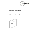
Operating instructions Wall scanner controls ES641x, ES642x, ES741x, ES742x eLOCK Operating instructions GB Wall scanner controls ES641x, ES642x, ES641x, ES742x Contents 1 Introduction .................................................................................................................. 4 About these instructions............................................................................................... 4 Explanation of the Symbols and Signal Words Used................................................... 4 Target group................................................................................................................. 4 OPERTIS Support........................................................................................................ 4 Up-to-date status of the information............................................................................. 5 2 Product Description ..................................................................................................... 6 Overview ...................................................................................................................... 6 Variations ..................................................................................................................... 6 Functional principle ...................................................................................................... 7 Detailed information ..................................................................................................... 7 3 Intended Use................................................................................................................. 8 Area of use................................................................................................................... 8 Condition of the product ............................................................................................... 8 Ambient conditions....................................................................................................... 8 Residual risk................................................................................................................. 8 4 Safety Instructions ....................................................................................................... 9 5 Use and Operation...................................................................................................... 10 Programming fittings and identifiers........................................................................... 10 Active extension of the fitting opening time................................................................ 10 Acoustic and visual signals ........................................................................................ 10 6 Servicing, Cleaning and Maintenance ...................................................................... 12 Intervals...................................................................................................................... 12 Cleaning and maintenance ........................................................................................ 12 Servicing .................................................................................................................... 12 7 Problems and Solutions ............................................................................................ 13 8 Product Specifications............................................................................................... 15 Declaration of conformity ........................................................................................... 15 Dimensions ................................................................................................................ 15 Technical data............................................................................................................ 16 9 Disposal ...................................................................................................................... 18 Product....................................................................................................................... 18 07/2013 OPERTIS 3 GB eLOCK Wall scanner controls ES641x, ES642x, ES641x, ES742x 1 Operating instructions Introduction About these instructions These instructions contain important notes and information on operation of the wall scanner controls ES641x, ES642x, ES641x and ES742x. Read through the instructions carefully and attentively. Keep the instructions in a safe place and pass them on to each subsequent user of the wall scanner controls. Explanation of the Symbols and Signal Words Used WARNING Indicates risks which could result in fatal or severe personal injuries. CAUTION Indicates risks which could result in fatal or severe personal injuries. CAUTION Indicates risks which could result in damage to property. Note Denotes information, notes and tips on optimum use of the instructions and the product. Target group These instructions are directed at competent personnel entrusted with the servicing, maintenance and disposal of trouble-free operation of the wall scanner controls and who has successfully completed suitable vocational training for these activities or has had the necessary appropriate experience. OPERTIS Support If you have any questions extending beyond the information provided in these instructions, please contact OPERTIS GmbH Prof.-Bier-Straße 1-5 D-34454 Bad Arolsen Tel.: +49 5691 87741-200 Fax: +49 5691 87741-281 E-Mail: [email protected] 4 OPERTIS 07/2013 GB eLOCK Operating instructions Wall scanner controls ES641x, ES642x, ES641x, ES742x Up-to-date status of the information All details on the product, images, dimensions and models correspond to the status at the time the product is delivered. We reserve the right to make changes due to technical progress and the resulting continuous improvement process to which our products are subjected. The current version of these instructions and further information is also available on our internet site www.opertis.de. Dated 07/2013 07/2013 OPERTIS 5 GB eLOCK Wall scanner controls ES641x, ES642x, ES641x, ES742x 2 Operating instructions Product Description Overview The following wall scanner controls are described in these instructions: Art. No. / Name Drawing ES64xxU… ES74xxU… Wall scanner control (concealed, underplaster (flush-mounted) installation) ES64xxT… ES74xxT… Wall scanner control (mounting rail installation) Variations Name Function Standard wall scanner control ES641x ES741x Activation of the internal or external relay for control of peripheral devices by holding an authorised identifier in front of the antenna. Multi-relay wall scanner control ES642x ES642x Activation of the internal or external relay for control of peripheral devices by holding an authorised identifier in front of the antenna. The wall scanner control up to 100 additional relays an external PCS system for 4,350 identifiers "taught" directly in the wall scanner control. Name Function Control Standard AddDelete wall scanner control ES741xxEL Activation of the internal or external relay for control of peripheral devices by holding an authorised identifier in front of the antenna. The wall scanner control is controlled by special programming ITs, see AddDelete operating instructions. 6 OPERTIS Control The wall scanner control is controlled by the eLOCK Center management software, see eLOCK system documentation software. 07/2013 GB eLOCK Operating instructions Wall scanner controls ES641x, ES642x, ES641x, ES742x Functional principle The OPERTIS eLOCK lock system ensures continuous public and commercial building fitout. Special fitting solutions are available for different door types. The wall scanner controls can be combined with different OPERTIS masking caps and housings and operated with an external power supply. In addition, external antennas can be connected. Interfaces are available for controlling external relays or peripheral devices and for networking via LAN modules. The multi-relay wall scanner controls control peripheral devices via a connected PCS system. Management and programming of the fittings, among other things the issue of access authorisations, takes place using the eLOCK Center management software. Optionally, programming with eLOCK AddDelete is also possible via three programming keys without additional software. Passive identifiers without their own power supply are available for authorisation at the fittings in the eLOCK lock system in different forms such as keys, key fobs, cards or customer-specific forms. These must be held on the wall scanner antenna for an authorisation check. Detailed information Further information on the product is given in Section 8 Product Specifications. 07/2013 OPERTIS 7 GB eLOCK Wall scanner controls ES641x, ES642x, ES641x, ES742x 3 Operating instructions Intended Use Area of use The wall scanner controls within an eLOCK lock system are designed to control peripheral devices, for example electric door openers, electric locks, motorised bolts, holding magnets, electrical door and gate drives, barrier systems, lifts, mailboxes, etc. The wall scanner controls are suitable for installation in the protected internal area. The flush-mounted versions are installed in flush-mounted boxes or on the surface with special spacer frames. The mounting rail version is intended for installation, e.g.: on a mounting rail in a switch cabinet. Condition of the product Wall scanner controls may only be used if they are in a technically perfect condition. Independent modifications and changes to the product are not allowed. Ambient conditions Use of the wall scanner controls in a particularly polluted environment, e.g. in aggressive gases or in extreme temperatures, is not allowed. If you have any questions, please contact OPERTIS Support. Residual risk If used properly and if the maintenance instructions are followed, this product will support your property security. However, the following residual risks cannot be excluded: In the event of failure of the mains power supply there is a risk of locking in or out. In this case the door can only be opened with mechanical aids. In the event of failure of the electronics there is a risk of locking in or out. The door can then only be opened with mechanical aids. In this case, contact OPERTIS Support. If a wall scanner is used to control access to a fuse box and a fuse is defective there is risk of locking in or out. The door can then only be opened with mechanical aids. OPERTIS recommends use of an uninterruptible power supply (UPS) to ensure operation of the wall scanner controls during a power failure. 8 OPERTIS 07/2013 GB eLOCK Operating instructions 4 Wall scanner controls ES641x, ES642x, ES641x, ES742x Safety Instructions The following safety instructions must be read and followed before use! OPERTIS does not accept any liability whatsoever for personal losses or injuries or damage to property caused by failure to note and follow these instructions! WARNING Risk of personal injuries and damage to property There is an increased risk of injuries if the wall scanner control or connection cables are touched while the power supply is switched on (electric shock!). The wall scanner control or connected peripheral device can be irreparably damaged. Carry out installation and maintenance work only if the power supply is switched off. Note and observe the VDE Guidelines (VDE-0100)! CAUTION Risk of damage to property Electronic components can be irreparably damaged if touched. Note and observe the regulations and notes in the DIN EN 61340-5-2 standard! CAUTION Unauthorised access after installation When delivered the wall scanner controls are in construction site mode. Access is possible with any OPERTIS identifier, even if they are not programmed. Program the authorisations immediately after installation to prevent unauthorised access; see eLOCK system documentation software. Check time and if necessary reset. 07/2013 OPERTIS 9 GB eLOCK Wall scanner controls ES641x, ES642x, ES641x, ES742x 5 Operating instructions Use and Operation Programming fittings and identifiers Fittings and identifiers are programmed using the eLOCK Center management centre or the eLOCK AddDelete system. Detailed information on this is given in the eLOCK system documentation software. Active extension of the fitting opening time If an authorised identifier is held in front of the wall scanner for longer than the defined fitting opening time, the wall scanner or the connected peripheral device remains activated until the authorised identifier is removed. Acoustic and visual signals The acoustic and visual signals of the connected wall scanner antenna depends on the programming. The programmed fittings in the AddDelete system and the fittings programmed using eLOCK Center have a different signalling concept. Note The complete visual and acoustic signals are included in the eLOCK system documentation "Signalling Concept" section. 10 OPERTIS 07/2013 GB eLOCK Operating instructions Wall scanner controls ES641x, ES642x, ES641x, ES742x The wall scanner antenna emits acoustic and visual signals for certain system states and events: Visual signal Acoustic signal Meaning red flashing - Wall scanner ready for use. 2x short blue-blue 1x ascending sound sequence Programming mode on. blue flashing - Programming mode active. – 1x descending sound sequence End of programming mode (automatic) 2x short greengreen 1x short high-pitch Wall scanner connection by authorised identifier 2x short red-red 1x long low-pitch No wall scanner connection, identifier not authorised 2x red-green 1x short high-pitch Wall scanner connection in construction site mode or permanent release mode, see eLOCK system documentation "Fitting Modes" section. 2x short red-red 4 x yellow 1x long low-pitch+ 4x short low-pitch System error! Dismantle wall scanner, contact ES Support! Important information During communication between a wall scanner antenna and an identifier or the programming equipment (e.g. programming mode) signalling takes place at this wall scanner antenna only. All other connected wall scanner antennas are inactive for this period. 07/2013 OPERTIS 11 GB eLOCK Wall scanner controls ES641x, ES642x, ES641x, ES742x 6 Operating instructions Servicing, Cleaning and Maintenance The servicing, cleaning and maintenance may be carried out by qualified personnel only. Warranty cover is excluded for damage caused by improper handling. Intervals Activity Interval Servicing 1 year Cleaning and maintenance Cleaning and maintenance of the wall scanner control is not necessary. Servicing CAUTION Risk of locking in or out Peripheral devices cannot be controlled without a fully functional wall scanner control and antenna. During the functional test of the wall scanner controls and antennas it is necessary to ensure that the systems controlled by the wall scanner control do not prevent anyone from passing through. The following functional tests must be performed once a year: Step 1 2 12 OPERTIS Activity Hold an authorised OPERTIS identifier in front of the connected antenna/s of the wall scanner control. Read fitting info, check time and date, see eLOCK system documentation. Result The connected peripheral device opens for the duration of the defined opening time. The wall scanner antenna signals as specified, see section “Active extension of the fitting opening time”.". If necessary, reset time and date, see eLOCK system documentation software. 07/2013 GB eLOCK Operating instructions 7 Wall scanner controls ES641x, ES642x, ES641x, ES742x Problems and Solutions Note Problems which can occur in or due to connected components (e.g. external antennas) and the solutions are described in the respective installation instructions. Problem Possible cause Solution Identifier is not recognised (no positive or negative acknowledgement). Identifier is defective. Replace identifier. Identifier is not given access. Identifier is not programmed or does not have the necessary authorisations. Program identifier, see eLOCK system documentation software. Wall scanner time is incorrect. Reset time, see eLOCK system documentation. Wall scanner control relay is defective. Replace wall scanner control. Peripheral device does not respond. Wall scanner antenna is Replace wall scanner control. defective. Identification attempt made at wall scanner control without internal wall scanner antenna. Peripheral device is off- Switch on power supply load. to the peripheral device. Peripheral device is incorrectly connected. Correct connection. Peripheral device is defective. Replace peripheral device. Connection conductors or cables are defective. Mounting rail version: "Fuse" is defective. A fitting time profile was Peripheral device removed from the wall remains activated. / Relay remains picked scanner during the fitting opening time. up. 07/2013 Replace connection conductors/cables. Replace "fuse". Change state of the fitting (several options): Use switch key Program new fitting time profile Perform switch function for online fittings via eLOCK Center. OPERTIS 13 GB eLOCK Wall scanner controls ES641x, ES642x, ES641x, ES742x Operating instructions Problem Possible cause Solution Wall scanner antenna has no ready signal. Power supply is defective or is not connected. Ensure power supply. Connection cable to the Ensure connection with antenna is defective or antenna. is not connected. Operating voltage not within the allowable range. Connect the correct power supply. Wall scanner control is defective. Replace wall scanner control. Wall scanner antenna is Replace wall scanner defective. antenna. Mounting rail version: Status LED of the wall scanner control is off. Each identifier is authorised to lock. 14 OPERTIS Relay has already picked up. Wait for relay to drop out. Power supply is defective or is not connected. Ensure power supply. Operating voltage not within the allowable range. Connect the correct power supply. Wall scanner control is defective. Replace wall scanner control. Fitting is not programmed ("construction site mode"). Program fitting, see eLOCK system documentation software. 07/2013 GB eLOCK Operating instructions 8 Wall scanner controls ES641x, ES642x, ES641x, ES742x Product Specifications Declaration of conformity OPERTIS GmbH herewith declares that the Wall Scanner Controls fulfil the basic standards and other relevant specifications of the 1999/5/EG and 2011/65/EU directives and that they are CE compliant. A copy of the statement of conformity can be ordered from the OPERTIS Support. Dimensions All dimensions are given in mm. Wall scanner controls, concealed, flush-mounted installation Wall scanner controls, mounting rail installation 07/2013 OPERTIS 15 GB eLOCK Wall scanner controls ES641x, ES642x, ES641x, ES742x Operating instructions Technical data Installation environment for concealed, flush-mounted installation Mounting depth ≥ 44 mm Installation diameter ≥ 53 mm or standard concealed, flushtype boxes with 60 mm fixing centres Mounting distance between wall At least 150 mm in 3D space scanner antennas Installation environment for mounting rail installation Housing See "Dimensions" section Mounting rail 35mm Mounting distance between wall At least 150 mm in 3D space scanner antennas Power supply / connections Power supply Automatic recognition: 12 - 24 V DC non-stabilised +/-10% or 24 V AC +/-10% The wall scanner control must be supplied from a power source with limited output according to EN 609501:2001. External antennas A maximum of 6 external antennas can be connected to a wall scanner control without internal antenna. A maximum of 5 external antennas can be connected to a wall scanner control with internal antenna. Power supply of the wall scanner antennas Operation of more than 3 antennas in total via one wall scanner control is only possible with an additional external power supply, 9 V DC. Length of the connection cable of external antennas ≤ 300m (series connection) Power consumption Depending on the number of connected antennas: 1 connected antenna: 1W 2 connected antennas: 1.6 W 3 connected antennas: 2.2 W 16 OPERTIS 07/2013 GB eLOCK Operating instructions Wall scanner controls ES641x, ES642x, ES641x, ES742x Interfaces Connection for external antennas Connection for control of a PCS system (multi-relay) Connection for an LAN module Connection for controlling external relays Current input max. 230 mA for 12VDC and with 3 connected antennas Outputs 1 relay output (Photomos, NO make contact) Concealed, flush-mounted version: Control of the external relay ES0532U with two electromechanical changeover contacts Mounting rail version: Control of max. two external ES0531T relays each with one electromechanical changeover contact Switching capacity Relay make contact/NO max. 60 V AC/DC / 2.0 A Connection diagram External relay for mounting rail installation Wall scanner antenna X Network Wall scanner antenna 1 Module LAN Wall scanner control External relay for installation in flushmounted boxes 07/2013 Power supply unit SPS Basic module Mains voltage 230 Volt SPS Expansion module OPERTIS 17 GB eLOCK Wall scanner controls ES641x, ES642x, ES641x, ES742x Operating instructions Specific data Operating temperature -20 °C to +55 °C Storage temperature -40 °C to +85 °C Air humidity for operation and storage max. 95 % non-condensing Degree of protection according to EN 60529 IP21 Memory capacity in standard wall scanner control: ES6… for ES5000 plus ES7… for eLOCK ES7… for eLOCK AddDelete Identifiers 60,000 80,000 100 Protection zones (membership of a group of fittings 296 30 - Events (authorisation attempts) 512 628 - Memory capacity in multi-relay wall scanner control: ES6… for ES5000 plus ES7… for eLOCK ES7… for eLOCK AddDelete Identifiers 4,350 4,350 - Protection zones (membership of a group of fittings 296 30 - 628 - Events (authorisation attempts) 512 9 Disposal Product Disposal in accordance with WEEE Directive 2012/19/EU: Do not dispose of product by throwing it in the local household waste. Return product to OPERTIS or dispose of at a municipal collection point for hazardous electrical wastes. 18 OPERTIS 07/2013 eLOCK Operating instructions 07/2013 GB Wall scanner controls ES641x, ES642x, ES641x, ES742x OPERTIS 19 OPERTIS GmbH Prof.-Bier-Straße 1-5 D-34454 Bad Arolsen Telefon: + 49 5691 87741-0 Telefax: + 49 5691 87741-310 [email protected] www.opertis.de M7000.45GBB V004 07/2013


