1
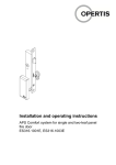
Installation and operating instructions Antenna in the Siedle housing ES314.2001 EN eLOCK eXpress Antenna in the Siedle housing Installation and operating instructions Contents 1 Introduction .................................................................................................................. 4 About these instructions ............................................................................................... 4 Explanation of the symbols and signal words used...................................................... 4 Target group ................................................................................................................. 4 OPERTIS Support ........................................................................................................ 4 Up-to-date information.................................................................................................. 5 2 Product Description ..................................................................................................... 5 Overview ...................................................................................................................... 5 Operating principle ....................................................................................................... 5 Signalling ...................................................................................................................... 6 Detailed Information ..................................................................................................... 6 3 Intended Use ................................................................................................................ 6 Area of use ................................................................................................................... 6 Condition of the product ............................................................................................... 7 Ambient conditions ....................................................................................................... 7 Residual Risk ............................................................................................................... 8 4 Safety Instructions ....................................................................................................... 9 5 Scope of supply ......................................................................................................... 10 6 Installation .................................................................................................................. 10 Overview .................................................................................................................... 10 Installation Tools Required ......................................................................................... 10 Connection at the controller........................................................................................ 11 Connecting Additional Antennas ................................................................................ 12 Functional test ............................................................................................................ 13 7 Operation and Control ............................................................................................... 15 Programming Terminals and Transponders ............................................................... 15 Optical and acoustic signals ....................................................................................... 15 8 Maintenance, Cleaning and Care .............................................................................. 16 Intervals ...................................................................................................................... 16 Cleaning and Care ..................................................................................................... 16 Maintenance ............................................................................................................... 16 9 Dismantling ................................................................................................................ 17 10 Problems and Solutions ......................................................................................... 18 11 Product Specification ............................................................................................. 20 Declaration of Conformity ........................................................................................... 20 Dimensions................................................................................................................. 22 Rating plate ................................................................................................................ 22 Note on the Operating System ................................................................................... 22 2 OPERTIS 12/2014 eLOCK eXpress Installation and operating instructions EN Antenna in the Siedle housing Technical data............................................................................................................ 23 12 Disposal ................................................................................................................... 24 Product....................................................................................................................... 24 Product packaging ..................................................................................................... 24 Notes:......................................................................................................................... 24 12/2014 OPERTIS 3 EN eLOCK eXpress Antenna in the Siedle housing 1 Installation and operating instructions Introduction About these instructions These instructions contain important information and instructions for installation operation of the wall scanner antenna in the Siedle housing. Read through the instructions carefully before starting the installation work and putting into service. Keep the instructions in a safe place and pass them on to each subsequent user of the antenna. Explanation of the symbols and signal words used WARNING Indicates hazards which could result in severe or fatal injuries. CAUTION Indicates hazards which could result in minor or moderate injuries. CAUTION Indicates hazards which could result in damage to property. Note Indicates information and tips for optimum use of the instructions and the product. Target group Faultless, safe function of the antennas depends to a large extent on proper installation. These instructions are therefore directed at competent personnel, who have completed suitable training or have experience appropriate for installation, maintenance, care, disposal and maintenance of antennas or comparable products. OPERTIS Support If you have any questions which are not answered by the information provided in these instructions, please contact OPERTIS GmbH Prof.-Bier-Straße 1-5 D-34454 Bad Arolsen Tel.: +49 5691 87741-200 Fax: +49 5691 87741-281 Email: [email protected] 4 OPERTIS 12/2014 EN eLOCK eXpress Installation and operating instructions Antenna in the Siedle housing Up-to-date information All details of the product, images, dimensions and versions are correct at the time of delivery of the product. We reserve the right to make changes in line with technical progress and the resulting continuous improvement process of our products. The current version of these instructions and further information is also available on our internet site www.opertis.de. Dated 12/2014 2 Product Description Overview The following antenna is described in these instructions: Art. No. / Name Drawing ES314.2001 Antenna in the Siedle housing Operating principle The OPERTIS eLOCK eXpress locking system ensures continuous, consistent fitout of a building. Special terminal devices are available for different door types. The antenna consists only of a reading unit. A connected controller is required for operation of the antenna. The power supply is provided via the controller or a suitable power pack. The antenna is used solely for data transmission and signalling. All security relevant functions such as evaluation of the communication with the transponder or control of the relay are carried out by a controller. The data between the antenna and controller is transmitted in encrypted form. This ensures the greatest possible protection against manipulation. The management and programming of the terminals, including the issue of access authorisations, is carried out using the eLOCK eXpress management software. 12/2014 OPERTIS 5 EN eLOCK eXpress Antenna in the Siedle housing Installation and operating instructions Various types of passive transponders without their own power supply, such as key fobs, cards or customer-specific types, are available in the eLOCK locking system for authorisation at the terminals. These must be held at the antenna for authorisation checking. Signalling The signalling of the terminals depends on the settings in the eLOCK eXpress software. Optical signalling is switched on by default. A buzzer can be switched on optionally for the acoustic signalling. The additional power consumption for the buzzer reduces the number of locking cycles that can be achieved by battery-operated terminals. Detailed Information Further information on the product is given in Section 11 "Product specification". 3 Intended Use Area of use The antennas are only used together with OPERTIS controllers. The antennas are suitable for installation in the Siedle door intercoms, Vario and Compact series. Combinations of the wall scanner products: Note The protected outdoor area is an area which is free from splashed water in all directions. Product Area of use TS controller / UP controller Suitable for use in the protected indoor area. Antenna in conjunction with - cover cap 80x80 - Spacer frame, low (optional) Suitable for use indoors or in the protected outdoor area. Antenna in conjunction with - cover cap 80x80 - Spacer frame IP65 Suitable for use outdoors. Antenna in conjunction with - cover cap 55x55 Suitable for use indoors or in the protected outdoor area. 6 OPERTIS 12/2014 EN eLOCK eXpress Installation and operating instructions Product Antenna in the Siedle housing Area of use Siedle antenna in built-in frame of Degree of protection to EN 60529 a Siedle Vario or Compact series IP54 door intercom system UP controller / Compact wall scanner in conjunction with - cover cap 80x80 - Spacer frame, high (optional) Suitable for use indoors or in the protected outdoor area. UP controller / Compact wall scanner in conjunction with - Surface-mounted (on wall) housing IP65 Suitable for use outdoors. UP controller / Compact wall scanner in conjunction with - cover cap 55x55 Suitable for use indoors or in the protected outdoor area. Compact wall scanner If using the individual antenna and UP controller components, refer to the information above. Condition of the product Antennas may only be used if they are in faultless technical condition. Independent modifications and changes to the product are not allowed. Ambient conditions Use in particularly harsh environments with conditions such as aggressive gases or extreme temperatures is not allowed. Note! In general, avoid laying the cables in the immediate vicinity of noise sources. Always use a shielded cable in ambient conditions with EMC disturbance. If you have any questions, please contact OPERTIS Support. 12/2014 OPERTIS 7 EN eLOCK eXpress Antenna in the Siedle housing Installation and operating instructions Residual Risk If used as intended and in compliance with the maintenance instructions, this product will help to maintain your property security. However, the following residual risks cannot be excluded: If the mains voltage fails there is a risk of being locked in or out. In this case it is only possible to open the door using mechanical tools. In this case, contact OPERTIS support. If the electronics or the connection cable to the controller fail there is a risk of being locked in or out. It is then only possible to open the door using mechanical tools. In this case, contact OPERTIS support. If an antenna is used for access control to a fuse box there is a risk of being locked in or out if a fuse is defective. It is then only possible to open the door using mechanical tools. 8 OPERTIS 12/2014 EN eLOCK eXpress Installation and operating instructions 4 Antenna in the Siedle housing Safety Instructions The following safety instructions must be noted and followed before use! OPERTIS does not accept any liability whatsoever for personal injuries or damage to property caused by failure to follow these instructions! CAUTION Risk of being locked in or out Without a functioning antenna in conjunction with a door locking mechanism, the door cannot be opened if the latch engages in the strike plate. When installing the antenna, keep the door open, or ensure that the door can be opened at any time without use of the wall scanner. CAUTION Risk of malfunctions Malfunctions can occur if the antenna is installed in the immediate vicinity of alternating electromagnetic fields (e.g. transformers, MRI scanners, etc.) and transmission equipment. Before installing, check whether any of the above-mentioned interference factors could affect the function of the wall scanner. CAUTION Risk of personal injuries The antenna is fitted with an LED which has a very bright light. If the antenna is supplied with voltage without a cover cap in front of the antenna the LED can dazzle. Do not look directly into the light of the LED. CAUTION Risk of damage to property Electronic components can be irreparably damaged if touched. Note and follow the regulations and instructions in the EN 61340-5-1 standard! Do not carry out any installation or maintenance work unless the power supply is switched off. Note and follow the VDE guidelines (VDE-0100)! 12/2014 OPERTIS 9 EN eLOCK eXpress Antenna in the Siedle housing 5 Installation and operating instructions Scope of supply The scope of supply includes the following parts: Part Name ES314.2001 Antenna in the Siedle housing Device screw (4 no.) 6 Installation Overview The installation is divided into the following activities: Connection at the controller Functional test CAUTION Risk of malfunctions If more than three antennas are operated via one controller, which is operated with PoE, the max. allowable power output of the controller can be exceeded. This can cause failure of the controller. An additional power supply (6-12V DC) must be used. Installation Tools Required You will need the following tools for the installation: Suitable screwdriver for installing screws available on site. Cable strippers or side cutters for stripping off the insulation and shortening the connection cable. 10 OPERTIS 12/2014 EN eLOCK eXpress Installation and operating instructions Antenna in the Siedle housing CAUTION Unauthorised access following installation In the as-delivered condition, the antenna is in construction site mode. Access is possible with any OPERTIS transponder, even if not programmed. Immediately following installation you should program the authorisations to prevent unauthorised access; refer to the eLOCK eXpress Quick Start Guide. Have the date and time reset, if necessary by your eLOCK eXpress trade partner. Connection at the controller Proceed as follows: Step 1 Activity Connect all necessary connection cables to the antenna and the controller, see "Pin Assignment" table: Set the terminating resistance, see section: "Connecting further antennas". Then fix the cover onto the bottom section using the device screws provided. 2 12/2014 Figure Connection terminal at the rear of the antenna: Rear of the antenna: Insert the antenna in the Siedle housing (order separately, not included) so that the LEDs are in the top right-hand side. OPERTIS 11 EN eLOCK eXpress Antenna in the Siedle housing Installation and operating instructions Pin assignment The following connections must be connected for the connection of the antenna with the controller. Connection description Connection Controller Antenna connection VCC 1 RS485_B Bus 1 Bus 2 RS485_A Bus 3 3 GND Bus 4 4 2 Connecting Additional Antennas A maximum of 4 antennas can be connected to one controller. The data connection is made via RS485 bus wiring (maximum allowable total length is 300 m), i.e. the connection cables are connected from the controller to the first antenna and from there to the second antenna, etc. Star-type cabling is not possible! Connection diagram Controller 1 2 3 4 Antenne 1 Antenne 4 1 1 2 2 3 3 4 4 VCC RS485_B RS485_A GND Terminating resistance For a secure RS485 bus data connection, a terminating resistance must be set at both ends of the bus cable. This is activated in the factory for all antennas in the ON position (ON-OFF switch, see Figure: "Front of antenna"). The switches at all other antennas within the bus connection must be set to OFF. Controller Antenna 1 Antenna 2 Antenna 4 ... (OFF) 12 OPERTIS (OFF) (ON) 12/2014 EN eLOCK eXpress Installation and operating instructions Antenna in the Siedle housing Figure: front of antenna 1 Signalling LEDs 2 Terminating resistance (ON position is labelled.) Functional test CAUTION Risk of being locked in or out Peripheral devices cannot be controlled without functional controllers and without a functional antenna. During the functional test of the wall scanner it is necessary to ensure that the systems controlled by the controller do not obstruct anyone at the passage/entrance. Note If a controller is controlled by several antennas, the functional test must be performed separately for each antenna. 12/2014 OPERTIS 13 EN eLOCK eXpress Antenna in the Siedle housing Installation and operating instructions Proceed as follows: Step Activity Result 1 Switch on power supply. Initialisation processes: The controller sets up communication with the connected antennas, duration max. 15 seconds. Signalling to the antenna: fast red flashing, 1 short green flash: Standby mode: Wall scanner in standby state. Signalling to the antenna: slow red flashing, relay has not picked up. 2 Hold any OPERTIS transponder in front. Controller's relays pick up, signalling to the antenna: 2 short red-green flashes and a short, high tone. Example: Activated door opens. After the connection time has expired: Relay of the controller drops out again. Signalling to the antenna: Short red flashing and short, high tone. Example: Activated door closes. 14 OPERTIS 12/2014 EN eLOCK eXpress Installation and operating instructions 7 Antenna in the Siedle housing Operation and Control Programming Terminals and Transponders Terminals and transponders are programmed using the eLOCK eXpress management software. Optical and acoustic signals Note The signalling of the terminals depends on the settings in the eLOCK eXpress software. Optical signalling is switched on by default. A buzzer can be switched on optionally for the acoustic signalling. All optical and acoustic signals are given in the eLOCK eXpress system documentation. In case of certain system states and events the wall scanner emits acoustic and/or optical signals: 12/2014 Optical signal Meaning 2x short blue-blue 1x short green Programming with the ToDo card completed successfully. 2x short blue-blue 2x short red-red Programming with the ToDo card not completed successfully. 2x short blue-blue 1x short red No programming job with the ToDo card exists for the terminal repeated short blue Programming in progress with the NFC stick. 2x short green-blue Use of the security card 2x short green-green Switching on of fitting by an authorised transponder. 2x short red-red No switching on of fitting, transponder is not authorised. 2x short red-green Switching on of fitting in construction site mode continuous short red Wall scanner is ready for use (standby) 2x short red-red 4x long yellow System error, contact sales partner. continuous short yellow The fire service transponder has been used. OPERTIS 15 EN eLOCK eXpress Antenna in the Siedle housing 8 Installation and operating instructions Maintenance, Cleaning and Care Maintenance and cleaning may only be carried out by qualified personnel. We do not provide any warranty whatsoever for damage caused by improper handling. Intervals Activity Interval Maintenance 1 year Cleaning and Care Care and cleaning are not necessary for the antenna. Maintenance CAUTION Risk of being locked in or out Without a properly functioning fitting, the door cannot be opened when the latch drops into the strike plate. Carry out functional checks while the door is open. The following functional tests are to be performed once a year, if necessary by the eLOCK eXpress trade partner: Step 1 2 16 OPERTIS Activity Hold an authorised OPERTIS transponder in front of the connected antenna(s) of the controller. Result The connected peripheral device opens for the duration of the defined opening time. The antenna signals as described above, see "Optical and acoustic signals" section. Reset the date and time. 12/2014 EN eLOCK eXpress Installation and operating instructions 9 Antenna in the Siedle housing Dismantling Note Dismantle in the reverse order. Therefore, refer to the figures in Section 6 "Installation". Proceed as follows: 12/2014 Step 1 Activity 2 To remove the antenna, the unlocking mechanism between two Siedle modules must be actuated using the Siedle Vario key (order separately, not included). The antenna can then be removed from the housing. 3 Disconnect the connection cables from the connection terminals of the antenna. To do this, press the lever of the terminal connector with a small screwdriver and pull out the cables. Figure Switch off power supply. OPERTIS 17 EN eLOCK eXpress Antenna in the Siedle housing Installation and operating instructions 10 Problems and Solutions Problem Possible cause Solution Antenna has no ready signal. Power supply is defective or not connected. Ensure power supply. Connection cable to the Ensure connection to antenna is defective or the antenna. not connected. Operating voltage not within the allowable range. Connect correct power supply (voltage). Controller is defective. Replace the controller. Antenna is defective. Replace antenna. Relay has already picked up. Wait for the relay to drop out. Transponder is not recognised (no positive or negative acknowledgement). Transponder is defective. Replace transponder. Antenna is defective. Replace antenna. Transponder obtains no access Transponder is not programmed or does not have the necessary authorisations Program the transponder. Controller has wrong date or wrong time Reset the date and time. If several antennas are connected, communication is in progress at another antenna (authorisation of a transponder or programming process). Wait for the communication process at the other antenna to finish. Antenna is temporarily not functioning, no signalling. 18 OPERTIS 12/2014 EN eLOCK eXpress Installation and operating instructions Problem Possible cause Antenna is not detected by the controller. Termination resistances Set the termination set incorrectly. resistances correctly. Each transponder is authorised for the lock. Wall scanner is not programmed ("construction site mode"). Program the wall scanner; see eLOCK eXpress Quick Start Guide. Failure of the controller and the antennas. Too many antennas at the bus. Secure power supply for several antennas from somewhere else. No optical or acoustic Signalling has been signalling at the switched off in the terminal. eLOCK eXpress software. 12/2014 Antenna in the Siedle housing Solution Switch on signalling in the software. OPERTIS 19 EN eLOCK eXpress Antenna in the Siedle housing Installation and operating instructions 11 Product Specification Declaration of Conformity Konformitätserklärung gemäß dem Gesetz über Funkanlagen und Telekommunikationsendeinrichtungen (FTEG) und der Richtlinie 1999/5/EG (R&TTE) Declaration of Conformity in accordance with the Radio and Telecommunications Terminal Equipment Act (FTEG) and Directive 1999/5/EC (R&TTE Directive) Hersteller The manufacturer Anschrift Address OPERTIS GmbH Prof.-Bier-Straße 1-5 34454 Bad Arolsen Deutschland/Germany erklärt, dass das Produkt declares that the product Wandleser System ES314.1000T ES314.1000U ES314.2000 ES314.2001 ES314.0001U Type Funkanlage Type Radio equipment Verwendungszweck Identifikation RFID (13.56MHz) Intended purpose Geräteklasse Class-1 Equipment class bei bestimmungsgemäßer Verwendung den grundlegenden Anforderungen des § 3 und den übrigen einschlägigen Bestimmungen des FTEG (Artikel 3 der R&TTE) entspricht. complies with the essential requirements of §3 and the other relevant provisions of the FTEG (Article 3 of the R&TTE Directive), when used for its intended purpose. Gesundheit und Sicherheit gemäß § 3 (1) 1. (Artikel 3 (1) a)) Health and safety requirements pursuant to § 3 (1) 1. (Article 3(1) a)) angewendete harmonisierte Normen: Harmonised standards applied... EN 50364: 2010 EN 60950-1:2006 + A11:2009 + A1:2010 + A12:2011 20 OPERTIS Einhaltung der grundlegenden Anforderungen auf andere Art und Weise (hierzu verwendete Standards/Spezifikationen) Other means of proving conformity with the essential requirements (standards/specifications used). 12/2014 EN eLOCK eXpress Installation and operating instructions Antenna in the Siedle housing Schutzanforderungen in Bezug auf die elektromagn. Verträglichkeit § 3 (1) 2, Artikel 3 (1) b)) Protection requirements concerning electromagnetic compatibility § 3(1)(2), (Article 3(1)(b)) angewendete harmonisierte Normen: Harmonised standards applied... ETSI EN 301 489-3 v 1.4.1 Einhaltung der grundlegenden Anforderungen auf andere Art und Weise (hierzu verwendete Standards/Spezifikationen) Other means of proving conformity with the essential requirements (standards/specifications used). Maßnahmen zur effizienten Nutzung des Funkfrequenzspektrums Measures for the efficient use of the radio frequency spectrum Luftschnittstelle bei Funkanlagen gemäß § 3(2) (Artikel 3(2)) Air interface of the radio systems pursuant to § 3(2) (Article 3(2)) angewendete harmonisierte Normen: Harmonised standards applied... ETSI EN 301 330-1 v 1.7.1 ETSI EN 301 330-2 v 1.5.1 Einhaltung der grundlegenden Anforderungen auf andere Art und Weise (hierzu verwendete Standards/Schnittstellenbeschreibungen)... Other means of proving conformity with the essential requirements (standards/interface specifications used)... Phone, fax, e-mail: Tel. +49 5691 87741-0 Fax +49 5691 87741-310 [email protected] Bad Arolsen, 2014-05-12 Andreas Steinkamp Ort, Datum Geschäftsführer / CEO Name und Unterschrift Place & date of issue Name and signature 12/2014 OPERTIS 21 EN eLOCK eXpress Antenna in the Siedle housing Installation and operating instructions Dimensions All dimensions given in mm. Rating plate Note on the Operating System The antenna is operated with the FreeRTOS operating system. Further information under: www.freertos.org 22 OPERTIS 12/2014 EN eLOCK eXpress Installation and operating instructions Antenna in the Siedle housing Technical data Installation environment Design Siedle colour scheme (white, silver metallic, titanium metallic, graphite brown metallic) Installation environment Siedle Vario / Compact intercoms Installation distance between antennas at least 100 mm in 3D space Power supply / connections Power supply The antenna is supplied with voltage (power) via a controller or a power pack. Antennas A maximum of 4 antennas can be connected to one controller. Connection cable single wire 0.14 - 0.5mm² Stripped length max. 9mm at the controller max. 5mm at the antenna Length of the connection cable of antennas ≤ 300m (connected in series) Pin assignment see Section 6: "Installation" Specific data 12/2014 Operating temperature -20 °C to +55 °C Storage temperature -40 °C to +85 °C Humidity for operation and storage max. 95% non-condensing Degree of protection: to EN 60529 IP54 in the Siedle frame OPERTIS 23 EN eLOCK eXpress Antenna in the Siedle housing Installation and operating instructions 12 Disposal Product Disposal in accordance with WEEE Directive 2012/19/EC: Do not dispose of product in the local household waste. Send product back to OPERTIS or dispose of it at a communal collection point for hazardous electronic wastes. Product packaging The product packaging must be disposed of through the local household or paper waste collection facility. Notes: 24 OPERTIS 12/2014 eLOCK eXpress Installation and operating instructions 12/2014 EN Antenna in the Siedle housing OPERTIS 25 EN Antenna in the Siedle housing 26 OPERTIS eLOCK eXpress Installation and operating instructions 12/2014 eLOCK eXpress Installation and operating instructions 12/2014 EN Antenna in the Siedle housing OPERTIS 27 Germany OPERTIS GmbH Prof.-Bier-Straße 1-5 34454 Bad Arolsen Telephone: + 49 5691 87741-200 Telefax: + 49 5691 87741-310 [email protected] www.opertis.de MB314.02EN V001 12/2014