1
Installation and wiring
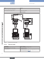
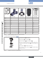
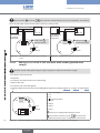
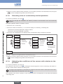
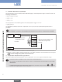
→→Place the seal 5 between the connector and the
EN 175301-803 fixed connector on the device
and then plug the 2508 connector into the fixed
connector.
5
6
→→Insert and then tighten the screw 6 to ensure
tightness and correct electrical contact.
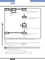
Figure 9 :
Assembling the female connector type 2508 (supplied)
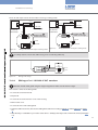
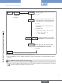
250 mA
+
-
+
-
12-30 VDC
4-20 mA input
(at external
instrument)
Power supply
2
3
I
1
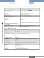
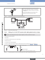
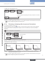
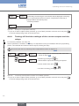
Figure 10 :
Wiring of the 4-20 mA output
7.4.2.
Wiring of a 12-30 V DC version with cable glands and no relays
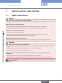
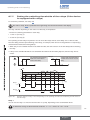
Seal the unused cable gland using the stopper supplied, to make sure the device is tight.
→→Loosen the screw from the lid.
→→Flip the lid.
→→Loosen the 4 screws from the cover of the housing.
→→Remove the cover.
→→Loosen the nuts of the cable glands.
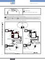
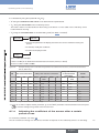
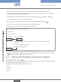
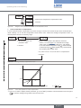
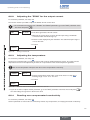
→→Insert the cable into the nut then into the cable gland, and wire according to Figure 12 or Figure 13.
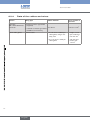
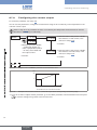
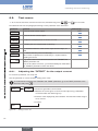
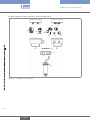
1: 4-20 mA output
1 2 3 4
A
2: V+
3: 0V
4: (functional earth)
A Sourcing or sinking mode selection switch
Figure 11 :
Terminal assignment of a version with cable glands, and no relays, energized with 12-30 V DC
19
English