1
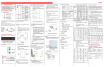
3.8 Unauthorized alterations and production of spare parts Any modification may be made to the machine only after consultation with the manufacturer. Using spare parts and accessories authorized by the manufacturer is in the interest of safety. Use of other parts may exempt the manufacturer from any liability. 4 Transportation and Storage Protect the pump against damage when transporting. The pumps may only be transported in a horizontal position and hooks or straps must be attached on the motor and pump end. Do not use the pump shaft for connecting any transportation aids such as hooks or straps. Pumps must be drained prior to their storage. Store pump in dry and protected areas and protect it against penetration of foreign bodies. Always store pump above the freezing point! 5 Installation and Connection 5.1 Mechanical installation The pumps must be properly fastened. The pipework must be installed so that no distortion of the pump can occur. The fluid inlet is on the face side of the flangeconnected pump mechanism. The clearance between the suction opening and the tank floor should be large enough to prevent the suction opening from becoming blocked even if the coolant is heavily polluted and the pump has not been operated for long periods. In order to reach the maximum flow rate it is recommended that the pipe diameter is as close as possible to the nominal pump connection diameter. Avoid the introduction of pipe bends (no angled sections). The installed pipes must be rated for the hydraulic pressures which occur during operation. The positions of the foot and pressure connection can be moved around the circumference to 3 different positions. On the S-type, the pipe connection can also be set to normal or parallel alignment to the pump axis. NPT ¼ NPT2 Dimensions in mm, *) Dimensions for motors up 7.4 HP ATTENTION Maximum tightening torque for piping connections NPT 2 is 130 ft. lbs. (170 Nm)! When installed the space around the pump must be large enough to provide sufficient cooling of the motor. The pump must never under any circumstances be used as a point for securing the piping. No forces or torques from the piping may be allowed to affect the pump. Pipes must be intercepted directly before the pump and connected with no tension. The pump may only be operated if installed to a suitable tank! A suction screw is in the suction side of the pump, risk of injury! Touching the rotating parts is forbidden! Reaching of the suction screw in the suction side of the pump must be prevented by fitting preventive measures! As particles and/or chips can be redirected from the pump suction at a high velocity, the tank design must incorporate appropriate protection, i.e. a tank cover, that prevents such objects from being ejected out off the tank. When pumping cooling- and cutting oils the following is to be adhered to: The geometry of the tank must be designed and executed in such a way that no flammable aerosol can develop (i.e. through velocity) during operation of the pump. The necessity of mist collection / exhaustion must be investigated and determined. (Danger of fire and explosion if ignition spark is present!) In order to avoid the formation of an ignition spark, no foreign particles may enter the tank. BAS6808 Edition 03/2014 Page 4 of 10