1
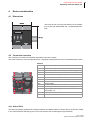
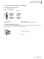
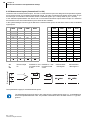
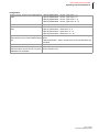
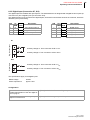
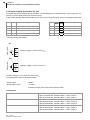
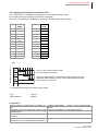
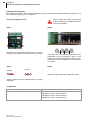
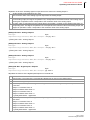
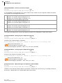
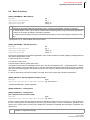
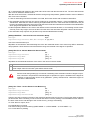
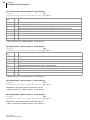
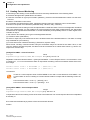
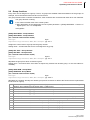
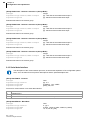
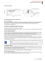
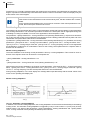
PSG Plastic Service GmbH
Operating instructions ETR112
6.2.5 Digital Input (Connection X7, X13)
The digital inputs are realized with optocouplers. The standard device is designed with 2 digital function inputs (at
connection X7) and 4 digital inputs (at connection X13).
The digital function inputs, as well as the digital inputs, work with functions fixed stored in the controller, which are
defined by the system setting.
PIN
X7
NEW
X7
OLD
Description
PIN
X13 X13
NEW OLD
Description
1
I2
IN2
Dig. function input 2
7
I1
DI1
Digital input 1
2
I1
IN1
Dig. function input 1
8
I2
DI2
Digital input 2
3
I-
IN-
Reference potential I *
9
I3
DI3
Digital input 3
10
I4
DI4
Digital input 4
Dig. function input
X7
Auxiliary voltage U+ from connection X7/8 or Uext
Auxiliary voltage U- from connection X7/9 or 0Vext
Digital input
X13
Auxiliary voltage U+ from connection X7/8 or Uext
Auxiliary voltage U- from connection X7/9 or 0Vext
The specifications apply for all digital inputs.
Rated voltage
30VDC
Power requirement
approx. 5mA
Configuration
Stipulate function which is implemented on ->[SP25] INPD/INPD - Function of Digital Inputs
activation/deactivation of the two digital inputs on plug X7.
Stipulates the function of the digital inputs/ ->[SP51] DIO /DIO - Digital Inputs / Outputs
outputs on terminal X13
Rev. 1.00.03
Technical changes reserved
19