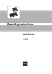
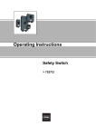
1
Operating Instructions Control and Distribution Box > 8150/5 Contents 1 Contents 1 2 3 4 5 6 7 8 9 10 11 12 13 14 15 16 2 Contents ................................................................................................................2 General Information ...............................................................................................2 Intended Use .........................................................................................................2 General Safety Instructions ...................................................................................3 Conformity to Standards ........................................................................................3 Transport and Storage ..........................................................................................3 Assembling and Dismantling .................................................................................3 Technical Data ......................................................................................................4 Installation Conditions ...........................................................................................5 Installation .............................................................................................................7 Putting into Service .............................................................................................11 Maintenance, Overhaul and Repair .....................................................................12 Inspections / Maintenance Checklist ...................................................................13 Accessories and Spare Parts ..............................................................................14 Disposal ...............................................................................................................14 EC-Declaration Of Conformity .............................................................................15 General Information 2.1 Manufacturer R. STAHL Schaltgeräte GmbH Am Bahnhof 30 74638 Waldenburg Germany Tel.: Fax: Internet: +49 7942 943-0 +49 7942 943-4333 www.stahl-ex.com 2.2 Operating Instructions Information ID-No.: Publication Code: Subject to alterations. 3 202162 / 815060300030 2011-05-23·BA00·III·en·01 Intended Use The control and distribution boxes are explosion protected equipment, certified for use in hazardous areas of Zones 1, 2 and 21, 22. They are used together with the built-in components to control, switch and transfer electrical energy. The devices are intended only for fixed mounting. 2 Control and Distribution Box 8150/5 202162 / 815060300030 2011-05-23·BA00·III·en·01 General Safety Instructions 4 General Safety Instructions The devices must be used only for the permitted purpose. Incorrect or impermissible use or non-compliance with these instructions invalidates our warranty provision. Any alterations and modifications to the device impairing its explosion protection are not permitted. Use the device only if it is undamaged and clean. WARNING Installation, maintenance, overhaul and repair may only be carried out by appropriately authorised and trained personnel. Observe the following information during installation and operation: 5 Any damage can invalidate the explosion protection National safety regulations National accident prevention regulations National installation regulations (e.g. IEC/EN 60079-14) Generally recognized technical regulations Safety guidelines in these operating instructions Characteristic values and rated operating conditions on the rating and data plates Additional instruction plates fixed directly to the device Conformity to Standards The relevant standards are listed in the EC Declaration of Conformity. 6 Transport and Storage Transport and storage are only permitted in the original packing. 7 Assembling and Dismantling If the explosion protected equipment is exposed to the weather, it is advisable to provide a protective cover or wall. Dimensions and weight data as well as the location of fastening points are given in the enclosed mechanical assembly drawings. To avoid condensation inside of the enclosure, it is recommended to install a R. STAHL breather, Type 8162. Depending on the installation location, the degree of protection decreases according to IEC/EN 60529. For any installation position, the degree of protection is IP64, if the breather is installed downwards, it is IP66. 202162 / 815060300030 2011-05-23·BA00·III·en·01 Control and Distribution Box 8150/5 3 Technical Data 8 Technical Data Marking Europe (ATEX) Gas explosion protection E II 2 G Ex d e ia/ib [ia/ib] ma mb q IIA, IIB, IIC T6, T5, T4 Gb Dust explosion protection E II 2 D Ex tb IIIC IP66 T130°C, T95°C, T80°C Db IECEx Gas explosion protection Ex d e ia/ib [ia/ib] ma mb q IIA, IIB, IIC T6, T5, T4 Gb Dust explosion protection Ex tb IIIC IP66 T130°C, T95°C, T80°C Db Certificates Europe (ATEX) PTB 09 ATEX 1109 IECEx IECEx PTB 09.0049 Electrical data Rated operational voltage max. 1100 V AC / DC depending on explosion protected components used Rated operational current max. 630 A depending on explosion protected components used Rated cross section 300 mm2 depending on explosion protected components used Ambient conditions Ambient temperature - 60 ... + 85 °C depending on explosion protected components used Mechanical data Degree of protection IP66 acc. to IEC/EN 60529 (depending on the built-in components used) Material Enclosure 8150/5-....-....-...-2...: stainless steel 1.4301 (AISI 304), brush finished 8150/5-....-....-...-3...: stainless steel 1.4404 (AISI 316L), brush finished Sealing gasket Silicone, foamed Mounting plate sheet steel, galvanized Wall thickness Enclosure cover min. 2 mm Mounting plate 3 mm Flanges Standard In the standard version, the enclosures are supplied without flanges. Option Depending on order requirements the enclosures can be installed on one or more sides with flanges; flange material: sheet steel, zinc-galvanised or stainless steel Cover fixing Standard with captive M6 stainless steel combo head screws Option with cover hinges Cover screws tightening torque 4.5 Nm Earth connection M8 blind rivet nut (1x): at the outside of the enclosure M8 rivet nut (1x): on mounting plate M6 bolt (1x): additionally on enclosures with cover hinges WARNING Powder coated enclosures must not be used in areas where intense electrostatic charging may occur. 4 Control and Distribution Box 8150/5 202162 / 815060300030 2011-05-23·BA00·III·en·01 Installation Conditions 9 Installation Conditions Clearance and creepage distances When installing components the clearance and creepage distances between the individual components as well as between the components and the enclosure wall must be sufficiently dimensioned. The creepage distances between the components must be tested and observed acc. to the guidelines of the relevant operating instructions. The clearance distances, dependent on the rated operational voltage of the fitted terminals, must be complied with. On all devices the distance between enclosure cover and connection screws of the built-in components have to be observed (with the conductor connected): minimum the values of the required creepage distances, e.g. ) 14 mm at 1100 V. Distance between connection parts for intrinsically safe and non-intrinsically safe circuits Partitions used to separate connection terminals shall extend to within 1.5 mm of the enclosure walls, or alternatively shall provide a minimum distance of 50 mm between the bare conducting parts of the connection terminals when measured in any direction around the partition. The minimum thickness of metal partitions must be 0.45 mm. They must be earthed and have sufficient strength and stiffness to ensure that they might not be damaged during connection work. Furthermore, the metal partitions must be equipped with appropriate current-carrying capacity in order to prevent a burn out or disconnection of the earth connection. The minimum thickness of nonmetallic, insulating partitions must be 0.9 mm. They must have an appropriate comparative tracking index (CTI) and must be supported in such a way that no deformation can occur. When fuses > 4 A are used, care must be taken to ensure that no inadmissible heating at the terminals of intrinsically safe ciruits can occur. Note for manufacture and operation: The installation of the equipment with type of protection intrinsic safety "Ex i" must be carried out in such a way that the distances as well as the clearance and creepage distances between intrinsically safe and non-intrinsically safe circuits according to IEC/EN 60079-14 are observed. Covers for combinations of non-intrinsically safe and intrinsically safe circuits All live parts which are not acc. to "Ex i" protection must be equipped with an inner cover which meets a minimum degree of IP30 protection when the equipment is opened. 202162 / 815060300030 2011-05-23·BA00·III·en·01 Control and Distribution Box 8150/5 5 Installation Conditions Intrinsically safe circuits In intrinsically safe circuits only insulated cables and conductors with a test voltage of at least 500 V AC and a minimum quality of H05 are permitted. Relating to insulation and separation of terminals and cables, it has to be observed that the insulation test voltage is the sum of the rated operating voltage of intrinsically safe and non-intrinsically safe circuits. In the case of "intrinsically safe to earth" there is a minimum insulation voltage value of 500 V (otherwise double the rated operating voltage of intrinsically safe circuits). In the case of "intrinsically safe to non-intrinsically safe" there is a minimum insulation voltage value of 1500 V (or double the rated operating voltage plus 1000 V). Clearance and creepage distances of intrinsically safe components The clearance and creepage distances between the blank, conductive parts of connection terminals of separated, intrinsically safe circuits to earthed or potential-free, conductive parts must be equal or larger than the values of IEC/EN 60079-11, table 5. If separated, intrinsically safe circuits have to be considered, the safety distance between the blank, conductive parts of the outer connections must be as follows: minimum 6 mm between the separated, intrinsically safe circuits minimum 3 mm to the earthed parts, if a possible connection to earth has not been considered in the safety analysis Terminal blocks in Ex e enclosure X Terminal bridging is only permitted if original explosion-protected accessories are used. X The partitions required for this purpose must be retrofitted if necessary. X For additional splice protection use core end sleeves or cable lugs. The cross-section of the splice protection must match the conductor cross-section. 6 Control and Distribution Box 8150/5 202162 / 815060300030 2011-05-23·BA00·III·en·01 Installation 10 Installation WARNING If the components are installed incorrectly, the explosion protection is not guaranteed. Observe the enclosed documents such as wiring diagrams. When installing additional components, make sure that these components have an "EC Type Examination Certificate" or "IECEx Certificate of Conformity". When performing this type of device modification, the rating and data plates must be adapted correspondingly. 10.1 Opening and closing the enclosure. For the versions with screw-on cover loosen the screws on the enclosure cover. If available, observe the cover lock at the rotary actuator. Rotary actuators installed on the cover may optionally have a cover lock. In this case the cover can only be removed or closed in one certain position. Open and remove the enclosure cover carefully. To close the enclosure cover, proceed in the reverse order. Observe the specified tightening torque. 10.2 Cable Entries WARNING The cable entries must be installed according to the manufacturer specifications. The following cable entries can be used to insert cables and conductors into enclosures: X plastic or metal cable glands for permanently installed cable conductors X plastic or metal cable glands with strain relief for conductors, that are not permanently installed To seal unused openings X plastic or metal stopping plugs can be used. Make sure that these components have an “EC Type Examination Certificate”, respectively an “IECEx Certificate of Conformity”. The IP degree of protection stated on the rating plate has to be observed. 10.3 Making of Additional Through Holes If additional through holes are required, e.g. for installing cable entries, breathing glands or other parts, the following has to be considered: Additional through holes can be laser-cut or punched. While punching please make sure that the surfaces remain even. When determining the through holes please consider the installing distances. Adjust hole diameter to the dimensions of the built-in parts or their seals. Do not damage circumferential sealing lips. 202162 / 815060300030 2011-05-23·BA00·III·en·01 Control and Distribution Box 8150/5 7 Installation 10.4 Usable Area for Cable Entries The usable area for cable entry installation is calculated as follows: (Length of enclosure inner wall - 2x10 mm*) x (Height of enclosure inner wall - 2x10 mm*) 2x10 mm* = circumferential rim of enclosure inner wall Attention Take the measurements on the face surface of the enclosure inner wall, not on the enclosure outer wall. Consider the positions of the blind rivet nuts to avoid damage. The required space for the built-in part results from: The width across corners of the cable entry plus space requirement for the used tool. Calculation of the usable area Usable area minus the area, which is required for the built-in parts. The following chart shows an example of the space requirements for R. STAHL cable entries. Cable entry thread diameter (( mm) Space requirement per pc. ( 12 mm ( 16 mm ( 20 mm ( 25 mm mm2 mm2 mm2 mm2 315 495 685 990 ( 32 mm 1560 mm2 ( 40 mm 2420 mm2 ( 50 mm 3425 mm2 ( 63 mm 5160 mm2 Calculation example X Dimensions of enclosure inner wall: 297 mm (Side D) x 122 mm (Side C) X Desired cable entries: M25 (15 pc), M32 (7 pc) Usable area (297 mm - 2x10 mm*) x (122 mm - 2x10 mm*) = 28254 mm2 2x10 mm* = circumferential rim of enclosure inner wall Required area for cable entries Qty. 15 pc 7 pc Type M20 M32 Area 15 x 685 mm 2 10275 mm2 7 x 1560 mm 2 10920 mm2 21195 mm2 28254 mm 7059 mm2 2 required area for cable entries usable area remaining usable area The area for the cable entries must be smaller than the calculated usable area. If this is not the case, a larger enclosure must be chosen. 8 Control and Distribution Box 8150/5 202162 / 815060300030 2011-05-23·BA00·III·en·01 Installation 10.5 Electrical connection WARNING Observe the data of the terminal manufacturer, for example the tightening torque. The conductor must be carefully connected. Do not damage the conductor (nicking) when removing the insulation. When removing the insulation, make sure that the conductor insulation reaches right up to the clamping points. Select suitable cables to be used and appropriate way of leading them to ensure that the maximum permitted conductor temperature and the maximum permitted surface temperature is not exceeded. The permitted ambient temperature at the built-in devices and components must not be exceeded. 10.6 Earth connection A protective conductor is always required. The external protective conductor connection is designed for cable lugs. The cable must run near to the enclosure. All blank, non-live metal parts have to be included into the protective conductor system, regardless of the rated operational voltage. Neutral conductors are considered to be live conductors. They have to be installed accordingly. Inactive metal parts are insulated acc. to EN 61439-1/ IEC 61641 and are not connected to earth. The data for potential equalization (PA), potential earth (PE) in intrinsically safe circuits are given in the documentation of the associated equipment. PE/PA connection for cable cross-section of up to 25mm2 Assembly 0245: internal connection external connection 1a 5 5a 4 3 1 6 7a 7 2 07855E00 Insert the earth bolt (1) and the sealing ring (1a) into a suitable bore of the enclosure wall (2) and fasten it by means of a hexagon nut (3). Put the inner PE cable lug (4) onto the earth bolt (1) and fasten it by means of the lock washer (5a) and hexagon nut (5). Put the external PE cable lug (6) onto the earth bolt (1) and fasten it by means of the lock washer (7a) and hexagon nut (7). 202162 / 815060300030 2011-05-23·BA00·III·en·01 Control and Distribution Box 8150/5 9 Installation PE/PA connection for cable cross-section of up to 70 mm2 (M8) and 120 mm2 (M10) Assembly 0238: internal connection external connection 7a 1a 5 5a 4 3 1 7 6 2 12780E00 Insert the earth bolt (1) and the sealing ring (1a) into a suitable bore of the enclosure wall (2) and fasten it by means of a hexagon nut (3). Put the inner PE cable lug (4) onto the earth bolt (1) and fasten it by means of the lock washer (5a) and hexagon nut (5). Put the external PE cable lug (6) onto the earth bolt (1) and fasten it by means of the lock washer (7a) and hexagon nut (7). 10.7 Wiring WARNING If the components are installed incorrectly, the explosion protection is not guaranteed. The required clearance and creepage distances must be adhered to. After connecting the cables, fasten the mounting rail or elements properly. Internal wiring The following cables can be used for the internal wiring: Type H07G H05V2 or similar types Temperature class Conductor cross-section T5 / T6 ) 0.5 mm2, Cu T6 External wiring Lead the connecting cable through the cable entries into the enclosure. Make sure that the cable diameter matches the clamping cross-section of the cable entries. Tighten the hexagon nut of the cable entries. Make sure that the tightness of the enclosure and the strain relief protection at the connection points are provided. For tightening torques refer to the operating instructions of the components. 10 Control and Distribution Box 8150/5 202162 / 815060300030 2011-05-23·BA00·III·en·01 Putting into Service Lay the cables in the connection chamber in such a way that X The minimum permissible bending radii for the respective conductor cross-section must not be less than the specified minimum. X the conductor insulation is not damaged because of sharp-edged or movable metal parts. Connect electrically Open the enclosure. Lay the connecting cables in such a way that the minimum permissible bending radii are less than the specified minimum. Connect the protective conductor. Remove loose metal particles, pollution and traces of moisture. Close the enclosure carefully after completing the work. Run insulation test according to IEC/EN 61439-1. After completing the electric installation, the following operations must be performed: Fastening of the protection against accidental contact. Setting of the tripping devices to the nominal value. Visual inspection for the presence of loose metal particles, soiling and traces of moisture. 11 Putting into Service WARNING The devices must be operated only in completely closed enclosures. For unused enclosure holes use R. STAHL stopping plugs, for example, Series 8290, for unused cable entries use R. STAHL plugs, e.g. Series 8161. Before putting into service Make sure that the device is not damaged. Make sure that the device is installed correctly. Remove any foreign objects from the device. Check the tightening torques. Check if all covers and partitions on live parts are in place and have been fixed. Back-up fuse Secure the system by means of the specified electric back-up fuse. Ensure sufficient short-circuit current at the mains connection (connection point) for reliable triggering of the fuse. 202162 / 815060300030 2011-05-23·BA00·III·en·01 Control and Distribution Box 8150/5 11 Maintenance, Overhaul and Repair 12 Maintenance, Overhaul and Repair WARNING Do not open when live! Do not open when non-intrinsically safe circuits are live! Exception: Devices with intrinsically and non-intrinsically safe circuits marked with "NON-INTRINSICALLY SAFE CIRCUITS PROTECTED BY INTERNAL IP30 COVER" may be opened while energized! The following details must be checked during maintenance: X Cables are held securely in place by the clamping points. X Compliance with the permitted temperatures (acc. to IEC/EN 60079 et seqq.) X Damage to the enclosure and sealing gaskets. 12 Control and Distribution Box 8150/5 202162 / 815060300030 2011-05-23·BA00·III·en·01 Inspections / Maintenance Checklist 13 Inspections / Maintenance Checklist Inspection schedule for Ex "d", "e" und "n" (D = Detailed inspection, C = Close inspection, V = Visual inspection) Check the following: Type of protection "d" Type of protection "e" Type of protection "n" Grade of inspection D C V D C V D C V Equipment corresponds to EPL/zone requirement of the installation site x x x x x x x x x Equipment group is correct x x x x x x x x x x x A Devices 1 2 3 Temperature class of the equipment is correct x 4 Electric circuit designation of the equipment is correct x 5 Electric circuit designation of the equipment is available x x x x x x x x x 6 Enclosure, windows and glass-to-metal seals and/or joints are okay x x x x x x x x x 7 There are no unauthorised modifications x 8 There are no visible unauthorised modifications x x x x x x 9 Screws, cable entries (direct and indirect) and blind plugs are correct, complete and tight. - Physical inspection x x x x x - Visual inspection x x x x 10 Joint faces are clean and undamaged, seals (if any) are okay 11 Joint widths are within the allowed limit values x 12 Rated value, type and arrangement of the lamps are correct x 13 14 15 Fracture-proof encapsulation and hermetically sealed devices are undamaged x x x x x x x x Electrical connections are tight and fixed properly x x Condition of the enclosure seal is okay x x x 16 Restricted breathing enclosure is okay 17 Motor fans have sufficient clearance to enclosure and/or covers x x 18 Breathing and draining devices are okay x B Installation 1 Appropriate cable and conductor types are used x 2 There is no visible damage to cables and wires x x x x x x x x x 3 Sealing of trunking, channels, pipes and/or conduits is okay x x x x x x x x x 4 Sealing devices and terminal sleeves are correctly filled x 5 The conduit system and the interface with mixed system are not damaged x 6 Earth connections, including any supplementary potential equalisations are satisfactory (for example, connections are properly fixed and conductor cross-sections are sufficient). x x x x x x x x - Physical inspection x x x x x x x x x x x x x x 7 Fault loop impedance (TN systems) or earthing resistance (IT systems) is sufficient x 8 Insulation resistance is sufficient x x x 9 Automatic electrical protective devices respond within the allowed limit values x x x x 10 Automatic electrical protective devices are set correctly (auto-reset not possible) x x x 11 Special operating conditions (if applicable) are observed x x x 12 Cables and/or wires not in use are correctly terminated x x x 13 Obstructions adjacent to flameproof joints are in accordance with IEC 60079-14 x 14 Installations with variable voltage/frequency are in accordance with documentation x x x C Environmental effects 1 Equipment is adequately protected against corrosion, weather, vibration and other adverse factors x x x 2 No undue accumulation of dust or dirt x x x 3 Electrical insulation is clean and dry x x x x x - Visual inspection x x x x x x x x x x NOTE 1 General: Equipment with both types of protection “d” and “e” is checked using a combination of both columns. NOTE 2 Item B7 and B8: When using electrical test equipment, take into account that there could be an explosive atmosphere in the vicinity of the equipment. 202162 / 815060300030 2011-05-23·BA00·III·en·01 Control and Distribution Box 8150/5 13 Accessories and Spare Parts Inspection schedule for Ex "i" Check the following: Grade of inspection Detailed inspection Close inspection Visual inspection x A Equipment 1 Circuit and/or equipment documentation is appropriate to zone classification x x 2 Installed equipment corresponds to the equipment specified in documentation - only applicable for stationary equipment x x 3 Category and group of electric circuit and/or equipment are correct x x 4 Temperature class of the equipment is correct x x 5 Installation is clearly labelled x x 6 There are no unauthorised modifications x 7 There are no visible unauthorised modifications 8 Safety barriers, relays and other energy limiting devices correspond to the certified type, are installed in accordance with the requirements of the certificate and are securely earthed if necessary. x 9 Electrical connections are fixed properly x 10 Printed circuit boards are clean and undamaged x B Installation 1 Cables are installed in accordance with the documentation x 2 Cable screens are earthed in accordance with the documentation x 3 No obvious signs of damage on cables and wires 4 Sealing of trunking, channels, pipes and/or conduits is satisfactory 5 Point-to-point connections are all correct x 6 Earth continuity is satisfactory (for example, the connections are fixed properly and the conductor cross-sections are sufficient) x 7 Earth connection maintain the type of protection x 8 The intrinsically safe circuit is isolated from the earth or grounded at one point only (refer to documentation) 9 Separation is maintained between intrinsically-safe and non-intrinsically safe circuits in common distribution boxes or relay cubicles x 10 If applicable, short-circuit protection of the power supply is in accordance with the documentation x 11 Special operating conditions (if applicable) are observed x 12 Cables and/or wires not in use are correctly terminated C Ambient conditions 1 2 x x x x x x x x x x x x x x x Equipment is adequately protected against corrosion, weather, vibration and other adverse factors x x x No undue accumulation of dust and dirt x x x 14 Accessories and Spare Parts WARNING Use only original R. STAHL accessories and spare parts. When installing additional components ensure that these components have an "EC Type Examination Certificate" or "IECEx Certificate of Conformity". 15 Disposal The national waste disposal regulations have to be observed. 14 Control and Distribution Box 8150/5 202162 / 815060300030 2011-05-23·BA00·III·en·01 EC-Declaration Of Conformity 16 Control and Distribution Box 8150/5 202162 / 815060300030 2011-05-23·BA00·III·en·01