1
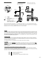
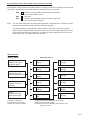
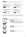
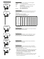
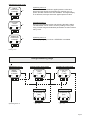
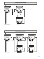
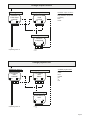
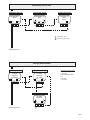
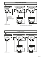
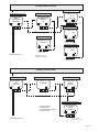
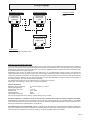
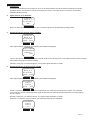
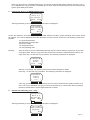
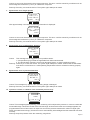
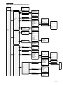
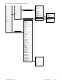
Operating instructions for pressure gauges PASCAL CI and PASCAL ∆P, Type Series CI . . . . User guidance and operating instructions software version 5.x Design Features ■ ■ ■ ■ ■ ■ ■ ■ ■ Microprocessor-controlled 2-wire pressure transmitter Text-oriented operating control via graphic display Parameterization on the transmitter or optional with a HART protocol Turndown 20:1 Measuring ranges 16 mbar up to 400 bar Output signal: 4..20 mA, 2-wire. HART protocol (option) Housing and wetted parts of stainless steel, type of protection IP 65 or IP 67 Explosion protection (gas) EMC test as per NAMUR 21 and valid EC guideline Contents Technical data Connection examples General information Menu overview Working menus Operating menus Mounting and operating instructions Operating-menu flowcharts Menu structur for Handheld-Communicator 275 page 1 page 2 page 3 page 4 page 4-6 page 6-12 page 12 page 13-15 page 16-17 Introduction These operating instructions refer to installation, commissioning, servicing and adjustment. Statutory regulations, valid standards, additional technical details in the relevant data sheet, details of the type plate and any additional certificates are to be observed along with these operating instructions. Safety instructions · Installation, operation and maintenance of the instrument may be executed by authorized personnel, only, using suitable equipment. · Prior to the disassembly of the pressure transmitter the impulse ducts between the measuring transmitter and the process have to be locked and relieved from pressure. · The standard nominal pressure rating and the permissible operating temperature of the gasket should be observed for all process connections. Operation outside the allowed nominal pressure rating, especially with clamp connections, is only possible with suitable clamps. In this case, note DIN 32676 for stipulations on heat resistance. · Pressure transmitters that are mechanically defective can cause injuries or give rise to process faults. Suitable precautions should be taken to avoid this. Technical Data Output signal : 4...20 mA Supply: 24 V DC : 12...50 V DC, standard Function range 12...30 VDC, Ex protection : Uninteruptible current measurement at test contacts Test output : 160 mbar ..... 400 bar, staggered Pressure ranges : EMC as per industrial standard Noise immunity : TÜV 99 ATEX 1414 X Ex-certification : 4 x working menus Menus 12 x operating menus Type of protection : IP 65 measuring ranges 1...40 bar rel. (option: IP 67 cable ventilation required) IP 67 measuring ranges 100...400 bar rel., and all absolute pressure measuring ranges Namur-recommendation : at state of November 2000 Further information required ? Hotline +49 (0) 4408 804-444 LABOM Mess- und Regeltechnik GmbH · P.O. Box 12 62 ∙ 27795 Hude ∙ Germany · Im Gewerbepark 13 ∙ 27798 Hude ∙ Germany Tel. +49 4408 804-0 ∙ Fax +49 4408 804-100 ∙ e-mail: [email protected] ∙ www.labom.com BTA-No. 002 Rev. 1F3 Page 1 Putting into service Connection examples Point-to-point operation with Connection terminals inline analog indication and HART-Communicator + TEST - Multidrop (bus) operation with PC or laptop and HART modem controller Regler - 1 3 + 2 insgesamt ohm 250...1100 250...1100 in total Ohm HARTCommunicator Laptop 250...500 Ohm # - + E# HART - Modem 4...20mA + 1 = 2 = 3 = = Test = Hilfsenergie auxiliary power + supply - supply Vacant terminal PASCAL Ci earth terminal connected to housing Connection for testing equipment for uninterruptible current measurement auxiliary Hilfsenergie power I I4jeweils mA each 4 mA + TEST - 1 3 2 E# P PASCAL Ci E# P PASCAL Ci E# P When the transmitter is switched on, an internal test program is run. The measured value is then displayed in the pre-selected working menu. Should the test program locate an error, a message is displayed, which is used by LABOM Field Service for fault analysis. General The CI type-series pressure transmitters may be exchanged with transmitters with standard 2-wire connection circuitry, and with the 4-20 mA output signal. The engineering unit "pressure" is converted into a proportional electrical signal by means of piezoresitive sensor elements. The signals are then digitally processed by a microcontroller. The capabilities of the pressure transmitters are thus superior to comparable analog systems. Operator inhibit The control system has an operator-inhibit feature under software control. It serves to inhibit parameter modifications. The inhibit may be enabled/disabled by simultaneously holding the left and right key pressed for at least 15 s. The operator inhibit is not available on the CI 2000 version with LC display. LC display The measured value is displayed on this display. The display also serves as a text-oriented user guidance facility. This matrix display allows the measured value to be displayed in excellent quality (with enlarged digits), and offers comprehensive textual explanation of programming and operator entry commands. 3-key operator control with CI 1000 version with LC display 3 keys, situated underneath the display, are used to operate the pressure transmitter operating functions, such as, trimming, spreading, damping, etc. Access is gained to the 3 keys by removing the bezel. The keys are lettered according to their function, as follows: KEY KEY KEY E :Page up in menu/increment :Cursor positioning :Entry/selection confirmation, ENTER function Page 2 3-key operator control with CI 2000 version without LC display The operation of the pressure transmitter without LC display is restricted to setting lower and upper range limits. Three buttons are visible when the closed front cover is removed. KEY KEY KEY E Load the actual applied pressure as lower range limit. The current settles at 4 mA. Not used Load the actual applied pressure as upper range limit. The current settles at 20 mA. Note: The ”Set lower range limit” and ”Set upper range limit” commands are not executed, when the actual pressure lies outside the limits of measuring range. The adjusted span is only altered by ”Set zero-point”, if the lower range limit + span is greater than the allowed upper range limit. If this is the case, the upper range limit is set to the maximum allowed upper range limit. If a minimum-span undershoot occurs, the “Set lower range limit ” command will not be executed. Menu overview Working menusOperating menus 11 factory data display ^ 12language change ^ 6measuring-circuit test ^ Display: Pressure value and output current [mA] 10 table function change ^ ^ 5 physical unit change 9 trimming change ^ 4 output function change ^ Display: Pressure value and % display 3 min/max values display ^ Display: Pressure value and sensor temperature [°C] 8 current trimming change ^ ^ 2 electr. damping change 7 alarm status change ^ 1meas.-range change ^ Display: Pressure value and analog bar graph 4 variants for displaying 12 operating modes for displaying and changing the measured value, may be parameters and operating states. selected for continuous display. Individual menus can be disabled, please specify when placing your order. Page 3 Working menus The measured value is continuously displayed in the working menu, as long as no adjustments are being performed on the transmitter. A choice of 4 working menus is available. 1 2 3 4 mbar ▲ ▲ E 1 2 3 4 mbar T = + 12.3°C E Key E selects next working menu Key ▼ selects 1st operating menu 1 2 3 4 mbar P = 34.56 % ▲ E mbar I = 16 mA ▲ E Display pressure value and % value, with reference to full scale value Key E selects next working menu Key ▼ selects 1st operating menu 1 2 3 4 ▲ ▲ ▲ Display pressure value and sensor temperature °C ▲ Key E selects next working menu Key ▼ selects 1st operating menu 100 0 Display pressure value and analog bar graph (% f.s.) Display pressure value and output current Key E selects 1st working menu Key ▼ selects 1st operating menu Should an operating menu be selected (per keystroke), the previous working menu is re-selected after approximately 5 min, if no key is pressed. The operating menu is re-selected by simultaneously pressing the left and middle keys. This function may be called up from any program item. An entry may be aborted with this function. Operating menus 1-3 Operating states may be queried, and parameters changed in operating menus. The functions of the keys are specified on the display. The following menus are available: NO ▲ ▲ E ^ ▲ MEAS.RANGE CHANGE YES Operating menu 1 The operating range is defined here by entering the desired pressure values for 4 mA and 20 mA current-output values. The limits are to be found in the data sheet. If the lower range value is changed, the pre-selected span remains unchanged, as long as the measuring range limits are not exceeded. E ^ NO ▲ ▲ E ^ ▲ ELECTR. DAMPING CHANGE YES Operating menu 2 The adjusted output-signal damping is displayed. The values may be changed. Range: 0...30 s, in 0,2 s-steps. E ^ NO ▲ ▲ E YES ^ Operating menu 3 Display min/max values for pressure and temperature. These values may also be deleted. E ^ ▲ MIN/MAXVALUES DISPLAY Page 4 NO Operating menu 5 The physical unit displayed in the working menu may be changed; the measured value is automatically converted to the chosen unit. The following units are available: mbar/bar; mWC; kPa; mmHg; psi; %; mA Nominal ranges and engineering units YES E E ▲ ▲ Operating menu 4 The transmission function is displayed. It can be toggled: LINEAR : 4...20 mA output function SQRT : 0...6 % linear, from 6 % characteristic curve is root extracting TAB : Transfer function according to user table max. 12 programmable points see operating menu 10 INVERS : 20...4 mA output function ^ ▲ OUTPUT FUNCTION CHANGE ^ Operating menus 4-9 ^ ▲ PHYSICAL UNIT CHANGE NO E ▲ ▲ YES E nominal ranges ^ ▲ NO E E ▲ YES ^ ▲ E mWS KPa psi % mA o o o o o o o o o o o o o o o o o o o o o o o o o o o mbar rel. mbar rel. mbar rel. 16 40 bar rel. bar rel. x x 100 bar rel. x o o o 400 bar rel. x o o o 1000 mbar abs. x 4000 mbar abs. x 16 bar abs. o x o o o o o o o o o o o o o o o o o standard (preselected) unit adjustable Operating menu 6 Output currents between 3.6 mA and 21.5 mA may be selected in 0.01 mA steps to test peripherals. Operating menu 7 The alarm status is displayed in case of malfunction. The output returns to < 3.6 mA irrespective of the pressure state. It can be switched to > 21.0 mA in case of malfunction. ^ NO x x x mmHg ^ ▲ ALARMSTATUS CHANGE bar 160 1000 4000 x o ^ MEASCIRC TEST adjustable engineering units mbar Operating menu 8 Indication errors in downstream devices may be trimmed by adapting the 4...20 mA signal. YES E ^ ▲ CURRENT TRIMMING CHANGE NO ▲ E YES E ^ NO ▲ ^ ▲ YES E E ^ TRIMMING CHANGE Operating menu 9 This function should only be performed, when the available pressure reference values are precise and stable. Two types of trimming are available: 1. Trimming the lower range value Apply and confirm pressure corresponding to the lower range value chosen in operating menu 1. The lower range value is corrected, only. The sensitivity remains unchanged (e.g. zero-point correction or installation position). 2. Trimming the span The procedure described in 1 should be followed. Then apply and confirm pressure corresponding to the full-scale value chosen in operating menu 1. Page 5 Operating menus 10-12 NO YES E E ▲ ▲ ^ ▲ TABLE FUNCTION CHANGE Operating menu 10 The transfer function between applied pressure value and electrical output signal can be defined by entering max. 12 points. Window functions are also available. The digital display is not affected, it always shows the applied pressure value. ^ NO YES E E ▲ ▲ ^ ▲ FACTORYDATA DISPLAY Operating menu 11 Querying the software version and selecting the basic setting. The transmitter can be reset to a factory setting. Factory trimming, nominal range and standard parameters are also reactivated by reset. ^ NO YES E Operating menu 12 The display language is shown. GER/ENGL is available. E ▲ ▲ ^ ▲ SPRACHE LANGUAGE CHANGE ^ Working menu Change measuring range ▲ Chg Chg E ^ ^ ^ ▲ E Nxt E ^ P (4 mA) [bar] .... P (20 mA) [bar] .... E ▲ OK ▲ UP ▲ Change digits RHT ▲ Move cursor E ▲ Change digits RHT ▲ ▲ ▲ UP ▲ Perform change ▲ Perform change ▲ ^ Operating menu 2 ▲ ▲ ▲ E Nxt E P (20 mA) [bar] + 8.500 ▲ YES ▲ ▲ ▲ E Display full scale value ^ NO P (4 mA) [bar] +1.000 ^ ▲ MEAS.RANGE CHANGE Display lower range value ^ ^ Operating menu 1 OK E Move cursor Page 6 Change electrical damping ^ NO ^ YES ▲ Chg ▲ E Nxt E ▲ ▲ ▲ E DAMPING [SEC] 10.0 ^ ▲ ELECTR. DAMPING CHANGE ^ Display damping Operating menu 2 E ^ Perform change UP ▲ ▲ ▲ ▲ DAMPING [SEC] .... ^ Change digits Operating menu 3 ▲ ▲ RHT E OK E Move cursor Display min/max values Chg Nxt ▲ E ▲ E Yes ^ Nxt E E Clear display T CLEAR ? + 22.6 -10.0 ▲ ▲ No ▲ E ▲ ▲ ▲ ^ ^ ^ P CLEAR ? = +689.9 = -220.3 ▲ No Chg E Clear display ▲ ▲ ▲ ▲ E E ▲ ▲ T [°C] + 22.6 - 10.0 ▲ ^ ▲ YES P [mbar] = +689.9 = -220.3 ▲ ▲ ▲ E ▲ Display T max/T min ^ ^ NO ^ ^ ▲ MIN/MAX VALUES DISPLAY Display P max/P min ▲ ^ Operating menu 3 Yes E ^ Operating menu 4 Page 7 Change output function NO ^ YES OUTPUT FUNCTION LINEAR ▲ Chg ▲ E E ▲ ▲ ▲ E ^ ▲ OUTPUT FUNCTION CHANGE Display output function ^ ^ Operating menu 4 Nxt Available output functions Linear Sqrt (software version 5.5 or higher) Tab Invers E ^ Select output function ▲ ▲ ▲ OUTPUT FUNCTION .... UP ▲ ▲ OK E E ^ Select output function Operating menu 5 Change physical unit NO YES ▲ ^ PHYSICAL UNIT MBAR Chg ▲ E E ▲ ▲ ▲ E ^ ▲ PHYSICAL UNIT CHANGE Display physical unit Nxt E ^ ^ Operating menu 5 Available physical units mbar/bar mWC KPa mmHG psi % mA ^ Perform change ▲ UP ▲ E ▲ ^ Operating menu 6 ▲ ▲ PHYSICAL UNIT .... OK E Select physical unit Page 8 Measuring-circuit test ^ Output test signal I (DESIRED V.) [MA] .... I (ACTUAL V.) [MA] 12.34 NO YES ▲ UP Change digits E OK E ▲ E 1 Move cursor ▲ ▲ E RHT ▲ ▲ ▲ E ▲ ▲ ▲ ▲ Select test signal ^ ^ MEASCIRC TEST ^ Operating menu 6 Nxt E 2 1 Test signal is output 2 Measuring signal is output ^ Operating menu 7 Change alarm status NO YES ▲ Chg ▲ ^ E E ▲ ▲ ▲ E ALARMSTATUS 22.5 MA ^ ▲ ALARM STATUS CHANGE Display alarm status ^ ^ Operating menu 7 Nxt Available alarm signals < 3.9 mA > 22.5 mA from software version 5.5: < 3.6 mA > 21.0 mA E ^ ▲ ▲ UP ▲ E ▲ ^ Operating menu 8 ALARMSTATUS .... ▲ Select alarm status OK E Select alarm signal Page 9 Change current adjustment ▲ E Chg ▲ E E ▲ 3 2 ^ ^ 3 actual measuring signal 4 corrected 4 mA signal 5 corrected 20 mA signal Perform change Perform change I (ACTUAL V.) = 4.015 * I (ACTUAL V.) = 20.01 * RHT ^ Operating menu 9 ▲ No RHT 4 Change digits Move cursor E E ▲ change digits Yes ▲ E ▲ ▲ E ▲ No ▲ ▲ ▲ output = 20 mA ▲ output = 4 mA 2 ▲ 1 ▲ ▲ 1 Nxt Chg ▲ E ▲ ▲ E Nxt E ^ ^ I (DESIRED V.) = 20.00 MA ^ I (DESIRED V.) = 4.000 MA YES NO ▲ Display full scale value ^ ▲ CURRENT TRIMMING CHANGE Display lower range value ^ ^ Operating menu 8 Yes 5 Move cursor * The numerals should be specified in full ! Change trimming ▲ Chg Nxt ▲ Chg ▲ E E ^ TRIMMING SPAN ▲ ▲ E E ^ ^ YES ▲ ▲ ▲ E Trimming the full scale value ^ ^ NO TRIMMING ZERO ^ ^ ▲ TRIMMING CHANGE Trimming the lower range value Nxt E ^ ^ Operating menu 9 ^ Confirm value Confirm value ZERO-PT. NEW SET SPAN PT. NEW SET ▲ No E Yes ▲ No ▲ E ▲ ▲ ▲ E Yes E ^ Operating menu 10 Page 10 Change table function Indicator evaluation ^ ▲ E ^ ▲ Nxt E E E Perform change POINT: 01 [%] .. ^ No ▲ change move digits cursor ▲ ▲ ^ default minimun 2, maximum 12 points No ▲ Yes E ▲ * ▲ Operating menu 11 POINT: 01 [mA] ... E ▲ ▲ Perform change Yes E E change move digits cursor ^ ▲ No Yes E ▲ ▲ NUMBER OF POINTS: .. ▲ ▲ ▲ Perform change* ▲ points 2...12 ^ Chg Nxt E ^ ▲ Chg ▲ ▲ YES NUMBER OF POINTS: 10 ▲ ▲ ▲ E ^ ^ NO ^ ▲ TABLE FUNCTION CHANGE ^ POINT: 01 10 % 4.00 mA Display no/points Operating menu 10 E change move digits cursor Display factory data ^ YES FACTORYDATA RESET? E ▲ Nxt ▲ Yes ▲ E No E ▲ E No: F.... CHANGE .... ▲ ▲ ▲ E Confirm factory data ^ ^ NO Display software version ^ ▲ FACTORYDATA DISPLAY ^ Operating menu 11 E ^ Perform confirmation ▲ ▲ No ▲ E ▲ ^ Operating menu 12 FACTORYDATA RESET ▲ Factory trimming, nominal range and standard parameters are reactivated. Yes E Confirm factory data and measured-value display Page 11 Change language ^ NO YES ▲ Chg ▲ E E Language available GER. ENGL. ^ SPRACHE LANGUAGE GER ▲ ▲ ▲ E Display language ^ ▲ SPRACHE LANGUAGE CHANGE ^ Operating menu 12 Nxt E ^ Select language ▲ UP ▲ E ▲ ^ Working menu Display: the chosen measured-value ▲ ▲ SPRACHE LANGUAGE .... OK E Select language Mounting and operating instructions The transmitters are adjusted and calibrated at the factory. They should only be installed and commissioned by competent personnel; user guidance and data sheets should be observed. The transmitters do not normally require any subsequent adjusting. You may need to correct the zero point, if you alter the installation position. Please note that the measuring span is not effected by the zero-point correction. Depending on the version, an aerated connecting cable (IP 67), or an integrated filter (IP 65) is used to compensate the internal pressure in excess-pressure ranges up to 40 bar. Higher measuring ranges or absolute pressure ranges do not require any pressure compensation to atmosphere. The named protection types are only achieved, when the transmitter has been correctly installed, both ring nuts screwed tight, and the cable diameters correspond with the nominal sizes of the sealing inserts in the case (conduit thread screwings). The integral EMC measures are only effective with a correct earth connection. State-of-the-art technology is used, and is continuously updated. Factory adjustment: Measuring range calibrated: 0...nominal range for 4...20 mA Damping programmed: 0s Signal output upon error: < 3.6 mA Phyiscal unit: bar or mbar Signal evaluation: linear User-guidance language: German We can also supply other basic settings - please specify with your order. Electrical equipment in hazardous areas should only be installed and commissioned by competent personnel. Modifications to devices and connections destroy the ex-proofing and the guarantee. The complete cable run, both inside and outside the hazardous areas in intrinsically safe circuits, should be equipotentially bonded. The limit values set out in the EC type Examination Certificate are to be observed. The CE designation for the transmitter certifies compliance with European Council guidelines (89/36/EWG), EMC legislation (13/11/1992), current generic standards, and product and basic standards. Clear operation in systems and plants is achieved when the conditons for screening, earthing, wiring and potential isolation are fulfilled. Page 12 Error messages 1. Introduction This section describes the errors that can occur in the Pascal device during the self-test (startup) and during operation. Some of these errors can be corrected by the device. The other errors can only be corrected by LABOM customer service. 2. Sytem test: No error detected PAS CAL REV:5.x SYSTEST: * OK * No errors were found during the system test. The device goes into the standard operating mode. 3. System test: Error external sensor number PAS CAL REV:5.x SYSTEST: ERR: EEP After approximately 3 seconds, the following information is displayed: FAILURE SENSORNO RESET! NXT 3 Cause: The sensor number of the sensor module could not be correctly read. This means that the internal compensating data cannot be checked for validity. Remedy: Press key 3 to reset the device. The system again attempts to restart. 4. System test: Error incorrect sensor number PAS CAL REV:5.x SYSTEST: ERR: SNR After approximately 3 seconds, the following information is displayed: SENSORDATA COPY YES NO 1 3 Cause: The sensor number of the sensor module does not match the internal sensor number. This message occurs after the sensor module has been replaced because the existing internal parameters no longer apply to the new sensor. Remedy: Press key 3 to reset the device. The system again attempts to restart. Press key 1 to start the copy procedure. The following information is displayed: SENSORDATA COPY ! ===> ! Page 13 If the copy procedure is completed without error, the device resets and the system restarts. However, if an error is identified, the copy procedure is repeated up to 3 times. After the third attempt, the device resets and the system again attempts to restart. 5. System test: Error in an EEPROM data block PAS CAL REV:5.x SYSTEST: ERR: EEP After approximately 3 seconds, the following information is displayed: FAILURE CHECKSUM EEP: 001 NXT 3 Cause: The checksum of an internal data block is invalid. With this condition, proper operation of the device cannot be ensured. The number displayed shows the data block in which the error was found. The following numbers are possible: 01 General parameters 02 Measurement range data 08 Function table 16 Temperature data 32 Compensating data Remedy: Some of these errors are cleared automatically when the sensor data are copied over by the inter nal program data. During a copy procedure, all previous entries are replaced with the factory set tings. Press key 3 to start the copy procedure. The following information is displayed: SENSOR DATA COPY YES NO 1 3 After key 3 is pressed, the device resets and the system attempts to restart. Press key 1 to start the copy procedure. The following information is displayed: SENSORDATA COPY ! ===> ! 6. If the copy procedure is completed without error, the device resets and the system restarts. However, if an error is identified, the copy procedure is repeated up to 3 times. After the third attempt, the device resets and the system again attempts to restart. System test: Watchdog error - entry PAS CAL REV:5.x SYSTEST: E R R : WDG After approximately 3 seconds, the following information is displayed: FAILURE WATC H D O G RESET! NXT 3 Page 14 Cause: An error was discovered in the program sequence. This error could be caused by conditions such as electromagnetic interference (”noise”) or a defective component. Remedy: Press key 3 to reset the device. The system again attempts to restart 7. System test: error illegal opcode PAS CAL REV:5.x SYSTEST: ERR: IOC 3 After approximately 3 seconds, the following information is displayed: FAILURE ILL. OPC RESET! NXT 3 Cause: An error was discovered in the program sequence. This error could be caused by conditions such as electromagnetic interference (”noise”) or a defective component. Remedy: Press key 3 to reset the device. The system again attempts to restart. 8. System test: error in temperature detection FAILURE KTY RESET! NXT 3 Cause: This message can be triggered by two possible causes. 1. A temperature lying outside the applicable limit values was detected. 2. The temperature measuring circuit was damaged (sensor or signal conditioning faulty). Remedy: Press key 3 to reset the device. The system again attempts to restart. Please note the transmitter must first be cooled down to a valid operating temperature before it will start functioning properly again. 9. System test: error in pressure detection FAILURE BRIDGE RESET! NXT 3 Cause: This message may appear if the measuring bridge is damaged. Remedy: Press key 3 to reset the device. The system again attempts to restart. 10. Operation: Overflow or underflow of the measurable pressure range mbar T=25.0°C overpressure Cause: This message appears (flashing) if the measuring cell is subjected to pressure or vacuum outside the measurable range. This does not refer to the nominal range. At the same time this error message appears, the programmed amount of fault current is output. As soon as the pressure measured is valid once again (lies within the measurement range), this fault current is automatically acknowledged and the transmitter functions normally. Remedy: Keep the pressure within the measuring range limits. Page 15 Menu structur Menu structur of Handheld-Communicator 275 Pres AO rel. AO abs. S-temp. -------- process variables Pres AO rel. AO abs. S-temp. Output fctn reset/test diagnostic/ service setup device device status system EEProm changes counter correct error! meascirc test loop test D/A trim PV setup sensor type range values range unit PV min/max va output fctn table function damp AO alarm typ sensor apply values correct error pres sensor type trim lrv trim urv range values range unit manufacturer model sensor type dev id tag date wirte protect descriptor PV snsr s/n message final asmbly num revision nos device information basic setup output fctn damp display opt sensor sens. Temp. setup all selftest masterreset factorydata rese PV setup LC-display display unit additional disp language P min P max clear P min max T min T max clear T min max number of points table points X1 Y1 X2 Y2 ... ... Y11 X12 Y12 universal rev fld dev rev software rev hardware rev pres sensor type trim lrv trim urv S-temp. temp unit sensor type range values range unit PV min/max va output fctn table function damp AO alarm typ analog output output HART output display output P min P max clear P min max T min T max clear T min max number of points table points AO rel. AO abs. meascirc test apply values output fctn table function damp AO alarm typ X1 Y1 X2 Y2 ... ... Y11 X12 Y12 loop test D/A trim number of points table points poll addr tag date description message dev id num reg preams LC-displ. display unit additiona disp language Page 16 X1 Y1 X2 Y2 ... ... Y11 X12 Y12 Menu structur of Handheld-Communicator 275 device information setup all panel setup setup device review Modifications reserved manufacturer distributor model sensor type PV snsr s/n dev id final asmbly num pres AO rel. AO abs. S-temp. P min P max T min T max range unit temp unit PV lrv PV urv PV lsl PV usl PV min span output fctn damp AO alarm typ tag date discriptor message poll addr num reg preams write protect universal rev fld dev rev software rev hardware rev LC-display display unit additional disp language loc menu items changes conter numer of points table points manufacturer model sensor type dev id tag date write protect. descriptor PV snsr s/n message final asmbly num revision display op loc menu items universal rev fld dev rev software rev hardware rev LC-displ. display unit additional disp language X1 Y1 X2 Y2 ... ... Y11 X12 Y12 BTA-Nr. 002 Page 17