1
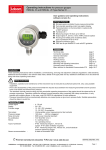
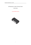
Operating instructions for pressure transmitter OPERATING INSTRUCTIONS PASCAL Ci, Type Series CI 101. und CI 120. TRANSMITTER PRESSURE PASCAL Ci Introduction These operating instructions refer to installation, commissioning, servicing and adjustment. Statutory regulations, valid standards, additional technical details in the relevant data sheet, details of the type plate and any additional certificates are to be observed along with these operating instructions. Safety instructions Installation, operation and maintenance of the instrument may be executed by authorized personnel, only, using suitable equipment. Warning: If the instrument is used incorrectly it is possible that serious injuries or damage can occur! Prior to the disassembly of the pressure transmitter the impulse ducts between the measuring transmitter and the process have to be locked and relieved from pressure. The standard nominal pressure rating and the permissible operating temperature of the gasket should be observed for all process connections. Operation outside the allowed nominal pressure rating, especially with clamp connections, is only possible with suitable clamps. In this case, note DIN 32676 for stipulations on heat resistance. Pressure transmitters that are mechanically defective can cause injuries or give rise to process faults. Suitable precautions should be taken to avoid this. CE marking The CE marking on the instruments certifies compliance with valid EU directives for bringing products to market within the European Union. The following directives are met: EMC directives EMC 2004/108/EG Pressure Equipment Directive PED 97/23/EG Ex directive ATEX 94/9/EG Ex approval Electrical equipment in hazardous areas should only be installed and commissioned by competent personnel. Modifications to devices and connections destroy the operating safety, the ex-proofing and the guarantee. The limit values detailed in the certificate of conformity are to be observed. Certificate no. marking TYPE SERIES CI 1011 CI 2011 The instrument can only be protected against electromagnetic interference (EMC) if the conditions for screening, earthing, wiring and potential isolation are met during installation. The mounting position should be taken into consideration when checking the zero output. Standard transmitters are adjusted at the factory for vertical mounting. Changes to the mounting position can cause zero shifts at pressure ranges < 2 bar. These drifts can be corrected by adjustment on site (see zero point correction). When the instrument is opened any contact with the electrical connections can affect the signals. This situation can be avoided by switching off the supply voltage or by disconnecting the signal circuit. The types of protection IP65/IP67 are only achieved, when both threaded rings have been screwed tight after electrical connection/parameterization. The instrument requires no maintenance. Instructions for the operation with diaphragm seal To avoid soiling and damage remove protective cap or wrapping in front of the separating diaphragm before mounting. Do not touch the flush mounted separating diaphragm, as there is a danger of deformation at measuring ranges to 10 bar / 150 psi. Instrument zero point and measuring characteristics could also be affected. Measuring instrument and diaphragm seal are a closed system and should not be separated . Avoid overtightening the process screw joints as this can result in zero displacements at the pressure transmitter (fixing error). When using systems with capillary for vacuum measurements always mount the pressure transmitter underneath the diaphragm seal. The instruments are set at the factory with pressure transmitter and diaphragm seal at the same height. Correct any differences in height between diaphragm seal and pressure transmitter arising from conditions on site on the pressure transmitter when placing the instrument into operation (see zeropoint correction). When correcting for elevation be aware of the adjustment limits. Be sure to install and securely fasten the capillary to avoid vibrations. Roll up overlengths with a minimum radius of 20-25 cm. Shock and changes in temperature can impact on measurements. Process and ambient temperatures can cause zero displacements at the pressure transmitter with some system designs. We can supply you with an error analysis. TÜV 99 ATEX 1414 X II 1/2 G Ex ia IIC T4/T5/T6 Ga/Gb II 2 G Ex ia IIC T4/T5/T6 Gb Mounting and operating Before mounting the instrument ensure that pressure range, overpressure resistance, media compatibility, thermostability and pressure port are suitable for the process at hand. Conduct process installation before electrical installation. Measuring instruments that should not have any oil or grease residues in the pressure port are marked „Free of oil and grease“. Gaskets must be chosen that are suited to the process connection and resistant to the measured medium. Check for pressure tightness when commissioning the transmitter. Do not insulate the temperature decoupler, as this would reduce the decoupling effect. Follow DIN 32676. Wire up the instrument with power switched off. Instruments with case protection IP67 and pressure ranges to 16 bar/ 250 psi are aerated through the connection cable. Place an aeratable cable in an aeratable connection chamber during mounting. This will compensate for atmospheric variations. LABOM Mess- und Regeltechnik GmbH P.O. Box 12 62 · 27795 Hude · Germany Im Gewerbepark · 27798 Hude · Germany Further13information required? Tel.: +49 (0) 4408 804-0 · Fax: +49 (0) 4408 804-100 e-mail: [email protected] · www.labom.com Zero-point correction Should you need to adjust the zero-point on site, then undo the front threaded ring to gain access to the controls. You will find instructions on using the keyboard in your manual. To set the measuring span, you should apply an accurate reference pressure. Please check the User Guidance for further information regarding operation and parameterization. . FURTHER INFORMATION REQUIRED? HOTLINE +49 (0) 4408 804-444 Hotline +49 (0) 4408 804-444 BTA-No. 022 Rev. 0B4 BTA-No. 013 Rev. 1B3 LABOM Mess- und Regeltechnik GmbH · P.O. Box 12 62 ∙ 27795 Hude ∙ Germany · Im Gewerbepark 13 ∙ 27798 Hude ∙ Germany Tel. +49 4408 804-0 ∙ Fax +49 4408 804-100 ∙ e-mail: [email protected] ∙ www.labom.com Technical Data Case design with hardened surface mat. no. 1.4305 Protection type with closed case IP65 inner chamber aeration via integrated filter IP67 inner chamber aeration via connection cable Electrical connection Cable entry for cable diameter 5...10 mm terminal screw connection 2.5 mm2 Temperature ranges ambient temperature: -10°C...+55 °C storage temperature: -25°C...+60 °C process temperature: -10°C...+90°C cleaning temperature (CIP) up to max. +140°C with horizontal flange mounting max. ½ h Measuring accuracy linearity error incl. hysteresis <+ 0.2 % f.s. optional <+ 0.1 % f.s. accuracy of adjustment: <± 0.1 % f.s. temperature effect see data sheet Supply voltage standard version · function range 12...50 V DC · max. permiss. 50 V DC Ex-design · permiss. voltage range function range 12...30 V DC max. permiss. 30 V DC Signal output 4...20 mA 2-wire circuitry Current limitation in output signal max. output current approx. at 21.5 mA Adjusting range You may adjust zero point and measuring span to wide limits from the keyboard. (see manual for details) Burden R≤ U - 12 V (Ohm) 23mA System filling silicone-free synthetic oil (standard) Installation position any, standard: adjusted at factory for vertical mounting Certificates/tests EMC directives 2004/108/EG Interference emission EN55011 Noise immunity EN61000-4-2:2001EN61000-4-6:2001 EN61000-4-16/ NAMUR NE21:1998 Caution Switch off device if it is installed in zone 0 and in temperature class T5 and T6 and it falls! Further details see data sheet D4-015 Dimensions/case/process connection Dimensions/case/process connection Connection diagram BTA-No. 013 BTA-Nr. 013 BTA-Nr. 013 BTA-Nr. 013 BTA-Nr. 013 BTA-Nr. 013