1
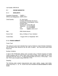
Operating Instructions for the WEGA model boat, Order No.: 2068 Brief description of the full-size vessel As the basis for our model we selected a typical schooner with topsail schooner rig. The term schooner was originally applied to two-masted sailing ships whose aft mast was taller than the forward one, but later - from the nineteenth century on - schooners were also built with several masts. Nowadays these vessels are generally operated as museum ships, and can be admired at international sailing events. A small number of these vessels are still operated as regular sail-training ships. Brief description of the model Ready-made model (ARTR) GRP hull Wooden deck and superstructure with lacquered finish Laser-cut ABS internal superstructure panels Metal and plastic detail fittings and small parts Ready-made rigging, easily installed Ready-made sails with sewn panels Hull, superstructure etc. spray-finished using matt paints Factory-installed SPEED 600 class electric motor Relatively easy installation of receiving system components Set contents: model, boatstand, small items Specification Overall length approx. Beam approx. Overall height approx. All-up weight approx. Scale approx. 1300 mm 275 mm 1150 mm 8.5 kg 1 : 30 Manufacturer’s declaration from Graupner GmbH & Co KG Content of the manufacturer’s declaration If material defects or manufacturing faults should arise in a product distributed by us in the Federal Republic of Germany and purchased by a consumer (§ 13 BGB), we, Graupner GmbH & Co. KG, D-73230 Kirchheim/Teck, Germany, acknowledge the obligation to correct those defects within the limitations described below. The consumer is not entitled to exploit this manufacturer’s declaration if the failure in the usability of the product is due to natural wear, use under competition conditions, incompetent or improper use (including incorrect installation) or external influences. This manufacturer’s declaration does not affect the consumer’s legal or contractual rights regarding defects arising from the purchase contract between the consumer and the vendor (dealer). Extent of the guarantee If a claim is made under guarantee, we undertake at our discretion to repair or replace the defective goods. We will not consider supplementary claims, especially for reimbursement of costs relating to the defect (e.g. installation / removal costs) and compensation for consequent damages unless they are allowed by statute. This does not affect claims based on legal regulations, especially according to product liability law. Guarantee requirements The purchaser is required to make the guarantee claim in writing, and must enclose original proof of purchase (e.g. invoice, receipt, delivery note) and this guarantee card. He must send the defective goods to us at his own cost, using the following address: GRAUPNER GmbH & Co. KG D-73230 KIRCHHEIM/TECK GERMANY No liability for printing errors. Technical modifications reserved! 03/2011 1 Gliders Brunel Drive, Newark, Nottinghamshire, NG242EG The purchaser should state the material defect or manufacturing fault, or the symptoms of the fault, in as accurate a manner as possible, so that we can check if our guarantee obligation is applicable. The goods are transported from the consumer to us and from us to the consumer at the risk of the consumer. Duration of validity This declaration only applies to claims made to us during the claim period as stated in this declaration. The claim period is 24 months from the date of purchase of the product by the consumer from a dealer in the Federal Republic of Germany (date of purchase). If a defect arises after the end of the claim period, or if the evidence or documents required according to this declaration in order to make the claim valid are not presented until after this period, then the consumer forfeits any rights or claims from this declaration. Limitation by lapse of time If we do not acknowledge the validity of a claim based on this declaration within the claim period, all claims based on this declaration are barred by the statute of limitations after six months from the time of implementation; however, this cannot occur before the end of the claim period. Applicable law This declaration, and the claims, rights and obligations arising from it, are based exclusively on the pertinent German Law, without the norms of international private law, and excluding UN retail law. Important safety notes You have purchased a kit which can be assembled to produce a fully working RC model boat when fitted out with the appropriate accessories. As manufacturers, we at GRAUPNER are not in a position to influence the way you install, operate and maintain the boat, nor the other components used in connection with the model. For this reason we are obliged to deny all liability for loss, damage or costs which are incurred due to the incompetent or incorrect use and operation of our products, or which are connected with such operation in any way. Unless otherwise prescribed by binding law, the obligation of the GRAUPNER company to pay compensation, regardless of the legal argument employed, is excluded. This includes personal injury, death, damage to buildings, loss of trade or turnover, interruption of business or other indirect or direct damages which are caused by the operation of the model. Under all circumstances and in all cases the company’s overall liability is limited to the amount which you actually paid for this model. The model is operated at the sole risk of the operator. To avoid injury to persons and damage to property please handle your model boat carefully and operate it conscientiously at all times. Before you run the boat for the first time it is important to check that your private third party insurance policy provides cover when you are operating model boats of this kind. If you are not sure, take out a special insurance policy designed to cover the risks of RC modelling. These safety notes are important, and must be kept in a safe place. If you ever dispose of the model, be sure to pass them on to the new owner. The following points are important, and must be observed at all times: This model is not suitable for children or young persons under fourteen years of age. The projecting parts of the model may be sharp, and the tips of aerials and masts could cause eye injuries. The parent or guardian must supervise the model’s assembly, as there are certain dangers inherent in the use of tools and adhesives. Always operate the model carefully when there are persons or animals in the water. Always keep well clear of people and animals. Do not run your boat in protected sites, animal or plant sanctuaries or sites of special scientific interest (SSSI). Check with your local authority that the location you wish to use is suitable for model boats. Never run the model in salt water. Never operate your boat in adverse conditions, e.g. rain, storm, wind above Beaufort Scale 3, choppy water or strong currents. Since the model is dependent upon the wind, it should only be operated in light breezes of 1 to 2 Beaufort (defined as ‘leaves moving slightly in the wind’). In stronger winds the boat may heel over severely and be impossible to control; in the worst case it could take on so much water that it sinks. The boat is also unsuitable for gusty conditions. GRAUPNER GmbH & Co. KG D-73230 KIRCHHEIM/TECK GERMANY No liability for printing errors. Technical modifications reserved! 03/2011 2 Before you run the model check that the radio control system is working reliably, and that all connections are secure. If dry cells are to be used as power supply, remember that they must never be recharged. Only batteries marked specifically as ‘rechargeable’ can safely be recharged. It is important to check the effective range of the radio control system before each session: switch on the transmitter and receiving system, ask a friend to hold the transmitter, and walk about 100 m away, holding the model. Your assistant should operate the controls constantly, and the model must respond reliably. Check whether the channel you wish to use is not already occupied. Never switch the system on if you are not sure whether “your” channel is already in use. Note that other transmitters and radio equipment are capable of causing serious interference to your model. If possible, ensure that no equipment of this type is in use in the vicinity while you are operating your model. Never work on the model’s power system unless the drive battery is isolated from the system. When the drive battery is connected, make sure that you and everybody else always keep clear of the area around the propeller, as this represents a serious injury risk. Do not exceed the recommended operating voltage. Higher voltages may cause the motor and / or the speed controller to overheat, and the electrical wiring could even melt. If this should happen, a fire could start, in which case the model would be wrecked. Check that all the drive train components work smoothly and freely. This applies in particular when you are running the model, as leaves and other detritus can get caught up in the power train. If this happens, the motor, the speed controller and / or the rudder servo may be ruined due to overloading. Before running the model check that the sheets are free-moving, and have not become tangled or caught up on the model. Dry cells and rechargeable batteries must never be short-circuited. Do not allow them to come into direct contact with water. Remove the drive battery and any dry cells from the boat and the transmitter before storing the model. Do not subject the boat to severe humidity, heat, cold or dirt. Secure the model and the transmitter carefully when transporting them, as they may be seriously damaged if they are free to slide about. Never operate the model on moving water (e.g. a river): as it could be washed away downstream if the wind changes, if interference occurs, or if the battery is depleted. If you have to salvage the model, take care not to risk your own life or that of others. Check regularly that the boat is completely watertight, as it may sink if too much water enters the hull. Before every run check the model for damage which could allow water to penetrate the hull. Allow the model to dry out thoroughly after every session. Care and maintenance Clean the model carefully after every run, and remove any water which has penetrated the hull. If water gets inside any of the RC components, dry them out and send them to your nearest GRAUPNER Service Centre for checking. Clean the model and the transmitter using suitable cleaning agents only. A lint-free cloth is ideal. Never use chemical cleaners, solvents, methylated spirit, white spirit or similar. Notes on operating the model boat When running the model, it is best to consider it as a powered sailing boat, i.e. the motor is more than just an auxiliary power unit. The model’s scale appearance inevitably involves compromises which affect its sailing qualities, and for this reason its handling under sail is not as good as that of less complex models. This simply means that you will need to use the motor for additional forward thrust even when running the boat as a sailing vessel. GRAUPNER GmbH & Co. KG D-73230 KIRCHHEIM/TECK GERMANY No liability for printing errors. Technical modifications reserved! 03/2011 3 Terms GRAUPNER GmbH & Co. KG D-73230 KIRCHHEIM/TECK GERMANY No liability for printing errors. Technical modifications reserved! 03/2011 4 Assembly instructions Carefully unpack the model, the masts and all the small items. NOTE: don’t forget the four davits: they are packed in white protective film, and are easily overlooked. Assemble the boatstand and glue the joints. Uses the tip of a knife to lever up the central leafspring in the receiver connector attached to the sailwinch, then cautiously withdraw the red wire and its contact from the connector housing. Bend the wire double and wrap adhesive tape round the bare contact to insulate it. NOTE: this measure is necessary because both the sailwinch and the speed controller feature a BEC system, and only one of them may be used. If you are installing the recommended RC components, the NAVY V40R features the more powerful BEC system, so this one should be used. Unscrew the sheet guide flange, and install the sailwinch in the appropriate position. Unscrew the bezel from the sailwinch switch, fit the switch through the opening from the underside, and screw the bezel on the switch again. NOTE: check that the bezel is the right way round (switch ON / OFF position). Press the switch into the opening. GRAUPNER GmbH & Co. KG D-73230 KIRCHHEIM/TECK GERMANY No liability for printing errors. Technical modifications reserved! 03/2011 5 Run the three sheets through the holes in the winding reel, and tie them all together. IMPORTANT: apply a drop of cyano-acrylate to the knot to secure it. IMPORTANT: ensure that the upper sheets are wound onto the upper reel. When you are satisfied, screw the sheet guide flange in place again. IMPORTANT: check that the sheets are not tangled or twisted before you secure the flange. Wind a short length of the sheets onto the winding reel, then fit the winding reel on the sailwinch and tighten the retaining screw. GRAUPNER GmbH & Co. KG D-73230 KIRCHHEIM/TECK GERMANY No liability for printing errors. Technical modifications reserved! 03/2011 6 Prepare the rudder servo by pressing the rubber grommets into the servo mounting lugs, and pushing the brass spacer sleeves through the grommets from the underside. Place the rudder servo in the appropriate aperture and fit the retaining screws. Use a 2 mm Ø bit to drill out the centre hole in the double-sided servo output lever. Fit the angled end of the pre-formed pushrod in the hole, and secure it with the retaining clip. The prepared output lever can now be screwed to the servo, after setting it to centre from the transmitter. GRAUPNER GmbH & Co. KG D-73230 KIRCHHEIM/TECK GERMANY No liability for printing errors. Technical modifications reserved! 03/2011 7 Solder a G2 connector to the motor wires, referring to the wiring diagram on page 13 (+ is red, - is black). Check the direction of operation of the motor: when the battery is connected, the motor shaft must rotate in such a way that the boat will be propelled forward. NOTE: the polarity of the G2 connector system is designed in such a way that the raised lug on the plastic housing is always the positive terminal (red wire). If you keep consistently to this arrangement, your drive batteries and speed controllers will always be compatible with each other, and reversed polarity problems will not arise. We recommend following one of the tips below in order to make it easier to solder the joints; this reduces the likelihood of damaging detail features on the model with the hot soldering iron. TIP 1: remove the motor: undo the grubscrews in the propeller, then withdraw the propeller. Loosen the motor retaining screws (accessible through the two holes in the deck - don’t remove the screws completely! - and then withdraw the motor to the point where the shaft coupling is exposed. Loosen the grubscrews in the coupling which clamp the motor shaft, and then remove the motor from the model. Reverse the sequence to re-install it. TIP 2: if you have a friend to help you, ask him or her to hold the boat at an angle, so that you can hold the wires outside the hull for soldering the connector. TIP 3: it is possible to solder the joints directly inside the model (see photo) if you have access to the tool known as a “third hand”. Check that the screws in the shaft coupling, the motor retaining bar and the propeller are tight, as they may have worked loose in transit. You can check this by pulling on the propeller: if there is axial play in the shaft, then one of the grubscrews is loose. Tighten any loose grubscrews cautiously, following TIP 1 above to gain access to them. IMPORTANT: we recommend that you apply a drop of thread-lock fluid, e.g. UHU schraubensicher (Order No. 952) to each grubscrew, as vibration when the boat is operating may cause them to work loose again. Connect the speed controller wires to those attached to the motor, and fix the controller to the inside of the hull using Velcro (hook-and-loop) tape. Connect the two battery connectors to the distributor lead (Order No. 3068). Attach the receiver to the inside of the coaming under the bridge superstructure. Stick the aerials of the HoTT receiver in place, with the final 30 mm of the aerial wires pointing upward; this will ensure optimum reception. If you are using a conventional 40 MHz receiver, the wire aerial must be deployed under the deck, and taped in place. IMPORTANT: it is essential to locate the aerial or aerials above the waterline, otherwise radio reception will not be possible. GRAUPNER GmbH & Co. KG D-73230 KIRCHHEIM/TECK GERMANY No liability for printing errors. Technical modifications reserved! 03/2011 8 Solder multi-strand copper cable of adequate length to the drive battery, and solder a G2 connector (socket) to the free ends. Place the battery in the centre of the model, and secure it with Velcro tape. Take great care to ensure that the battery cannot shift, as sailing boats are capable of heeling (leaning over) at considerable angles. The final trim is carried out later, when the boat is complete, by installing additional ballast. Attach the bowsprit to the model: withdraw the retaining pin from the bracket on the deck, slide the bowsprit through the opening and into the hull before re-fitting the pin to secure it. Connect the bowsprit rigging to the rings already attached to the model. The next step is to prepare the schooner mast and the mainmast by connecting the throat halyard from the upper gaff throat fittings to the ring at the top. Check at the bottom that the gooseneck fittings engage fully. If the brass pins are loose enough to rotate, apply a drop of cyano to glue them to the masts. GRAUPNER GmbH & Co. KG D-73230 KIRCHHEIM/TECK GERMANY No liability for printing errors. Technical modifications reserved! 03/2011 9 Erect the masts on the deck, ensuring that they engage fully in the mast bases. Connect the shrouds and backstays of both masts. Connect the forestay and the mainstay, then repeat the procedure with the flying jib and inner jib. Glue the two yards to the schooner mast with a drop of cyano before attaching the braces to the yards. Finally attach the square sail bunt lines and sheets. Set the sailwinch to minimum travel, then run the sailwinch to the end-point at which the sails are fully close-hauled. Tie the sheets to the booms, but use knots which can be loosened again later. Slacken the sails until the winch is at the other end of its travel. If the linear movement is insufficient, increase the travel at the winch. CAUTION: since the winch travel is now greater in the ‘close-hauled’ direction, the sheets must be loosened at the booms before you make this adjustment. The sails can now be adjusted in a similar manner. When you are confident that the sail settings are correct, you can secure the sheets permanently. GRAUPNER GmbH & Co. KG D-73230 KIRCHHEIM/TECK GERMANY No liability for printing errors. Technical modifications reserved! 03/2011 10 Glue the radar apparatus in the intended position, and insert the three pins. Glue the four davits in the openings in the deck. GRAUPNER GmbH & Co. KG D-73230 KIRCHHEIM/TECK GERMANY No liability for printing errors. Technical modifications reserved! 03/2011 11 Place your finished, fully equipped model in the water, so that you can install the ballast weight and adjust the boat’s trim; scrap steel strip from your local metal factor is a good form of ballast. Place the ballast weights as low down in the hull as possible. Once the model is floating correctly, fix the ballast in place really securely; it must be impossible for it to shift when the boat is in the water. TIP: it is best to use Velcro tape for this, so that you can adjust the boat’s trim at any time, or remove the ballast to make the model easier to transport. Sailing Sailing a model yacht is not difficult once you are familiar with the interaction between the wind direction, the boat’s heading and the appropriate sail settings. Before you sail the model for the first time, we recommend that you read all you can on the theory of sailing, e.g. by reading one of the many books on the subject. The following section just provides a short, basic introduction to the subject. The various points of sailing (see sketch; special terms are printed in Italics) A sailing boat can never sail directly into wind (black arrow (W)). In the 90° sector (dark grey area) the sails will always flutter (shiver), and generate no forward thrust. Only when the boat bears away to about 45° off the wind direction will it start to pick up speed with the sails close-hauled (transition from dark grey area to light grey area (2a) to (2b)). This course is termed luffing. A sailing boat can only make headway into the wind on this course and with the sails close-hauled; the procedure is known as tacking, and involves sailing in a zig-zag pattern: for a while on the port tack (mainsail on the left-hand (port) side of the boat (2a)), then, after going about (the boat’s bow turns through the wind, from position (2a) via (1) to (2b)), for a while on the starboard tack (mainsail on the right-hand (starboard) side of the boat (2b)), etc. Fast, efficient tacking with a sailing boat demands a good eye and considerable manual skill, and ranks as the true art of sailing. The other courses are not so demanding. If the wind is blowing from the side, the sails are slackened (paid out) just to the point where they no longer shiver, i.e. around 30° to 45° relative to the boat’s longitudinal axis. This course is known as sailing with wind abeam ((3a) wind abeam on the port bow / (3b) wind abeam on the starboard bow). Segel-Kursskizze - Sketch of the points of sailing Anlufen - Luffing Abfallen - Bearing away If the boat bears away even further (bearing away: the boat turns away from the wind, i.e. the stern turns increasingly in the direction of the wind (II) / luffing: the boat’s bow turns increasingly towards the direction of the wind (I), ending up on a course with free wind, where the sails are paid out to about 60° to the boat’s centreline (4a / 4b). The boat only attains its maximum speed on these two headings. If the boat is sailing directly away from the wind (downwind), we speak of running before the wind. On this course the sails should be paid out as far as possible (approx. 90° to the boat’s centreline). Differential pressure conditions on the sails cause the jib to turn to the opposite side to the mainsail by itself, but this situation can also be generated deliberately by small rudder / course corrections. If the wind is or becomes too strong, the bow of a sailing boat can very easily be pushed under the water. If the boat is sailing with free wind, is brought into a position before the wind using the rudder (bearing away), GRAUPNER GmbH & Co. KG D-73230 KIRCHHEIM/TECK GERMANY No liability for printing errors. Technical modifications reserved! 03/2011 12 and is then steered back to a free wind heading using the rudder (approximately at right-angles to the former course with free wind), the boat is said to have performed a gybe. Gybing is complete when the main boom, paid out a long way, swings from one side of the boat to the other. Steering characteristics / Sailing characteristics Variations in wind pressure make it difficult for a sailing boat to maintain its course by itself; gusts of wind may cause it to luff up by itself, i.e. turn into the wind to a greater or lesser extent. This can be prevented by slightly paying out the sails in good time, and also by applying slight opposite rudder if necessary, until the gust is past. If the boat should bear away, the sails should be paid out at the same time as the necessary corrective rudder movement is applied. Otherwise, in fairly strong winds the boat will tend simply to continue stubbornly in a straight line, ignoring the corrective rudder commands. Please note that any sailing boat will turn uncontrollably into the wind if the breeze is too powerful. This means that the sail area is too great; if there is no alternative smaller sail suit available, sailing is not possible in these conditions. Wiring diagram Speed controller Motor G2 connector Drive battery 3068 Receiver Sailwinch Maiden run Wait for a day with optimum wind conditions, and seek out a stretch of water where you can easily salvage the boat if necessary. Charge up the batteries, and check the model’s working systems. Ensure that all parts are securely attached. Now you are ready for the boat’s maiden run. Be cautious at first, and take your time to get used to its sailing characteristics and handling. Don’t sail the model too far from the bank initially. We hope you have loads of fun sailing your WEGA! The following items are also required (not included in the set) Order No. Description 33112 mx-12 HoTT computer RC system 5173 REGATTA ECO sailwinch 2875 NAVY V40R speed controller 768 Lead-acid battery, 6 V / 10 Ah 3068 Y-lead, G2 connectors 2989 Plug + socket, G2 3389 High-flex copper cable, 2.5 mm² 3368 Velcro tape, 500mm Plus approx. 2 kg ballast weight, e.g. steel strip from a metal fabrication plant; visit your local metal-working company and enquire about scrap material. We recommend flat rectangular-section strip. Brass strip is also suitable, but is more expensive. GRAUPNER GmbH & Co. KG D-73230 KIRCHHEIM/TECK GERMANY No liability for printing errors. Technical modifications reserved! 03/2011 13