1
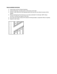
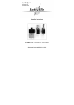
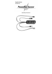
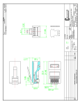
Operating Instructions
Operating Instructions
Featuring seven servo-pulse amplifiers plus
two independent voltage-controllers
POWER BOX 40/24 Competition
Dear Customer,
we are delighted that you have decided to purchase the PowerBox 40/24
Competition from our range. Your valuable model aircraft can now be fitted with
one of the most capable battery backers available, enabling you to couple two batteries and also monitor the voltage of both packs constantly. The unit stores the
minimum voltage of both batteries, and you can call up this information after each
flight. The PowerBox 40/24 Competition features an integrated two-way signal
amplifier for each of seven receiver channels connected to the backer, allowing you
to connect up to 4 servos to a single output without problem. This backer also provides a power supply for receiver and servos of 5.9 Volts (+/- 0.1 Volts) with very
accurate linear stabilisation. This is generated by an extremely low-loss ICcontrolled regulator (0.12 Volt reduction: very low waste heat).
Although this battery backer is simple to operate, you do need to understand certain points if you are to exploit its advantages to the full. Please read through these
instructions, and you will quickly feel ‘at home’ with your new accessory.
Table of contents
1.
2.
3.
4.
5.
6.
Functions of the Dual-Power-Control system...........................
Specifications .........................................................................
Connections and Controls.......................................................
Information on usage and security ..........................................
Sensor Switch.........................................................................
Guarantee conditions…………………………………………….……
1.
Functions of the Dual-Power-Control system
Page 3
Page 5
Page 5
Page 7
Page 8
Page 10
The backer is intended exclusively for use in modelling, and the sole approved
application is in radio-controlled models. It must be powered by a D.C. current
source, corresponding to a five-cell NiCd or NiMH battery, or two Lithium-Ion or
Lithium-Polymer cells (7.4 Volts).
Never connect the unit to a mains PSU!
For each of the 7 most important channels of your model aircraft you can connect
a maximum of four servos directly to the battery backer, without any problems regarding the servo signal voltage. In each case the signals for the 7 channels are
amplified by a two-way amplifier to a level which ensures that the stated number
-2 -
POWER BOX 40/24 Competition
of servos can safely be connected to the receiver via the PowerBox 40/24 Competition even when long cables are in use.
A special circuit is employed which de-couples the individual outputs of each servo
socket from each other; that is why it is possible to connect up to 4 servos without
any one servo affecting the others.
When long servo leads are used there is a danger of RF interference signals reaching the receiver by that route, but the integral servo signal amplifiers also effectively
prevent this by blocking the interference. For this reason ferrite rings are not required for de-coupling the servo cables when this backer is used.
A further important performance feature of the PowerBox 40/24 Competition is its
extremely accurate linear stabilisation circuit for the power supply to the receiver(s)
and servos. The stabilisation circuit takes the form of two independent voltage
regulators, each of which is capable of supplying a current of up to 20 A at a voltage of 5.90 V (accuracy +/- 0.1 V). This means that the unit is the first ever to provide a power supply which fulfils the maximum stated voltage tolerance specified by
all RC manufacturers!
If you wish to use batteries other than NC or NiMH types, e.g. Lithium-Ion or Lithium-Polymer batteries, the PowerBox 40/24 Competition is the outstanding
choice. In fact, the initial idea of voltage stabilisation was developed specifically with
these new-technology batteries in mind. We have world-wide experience with our
-3 -
POWER BOX 40/24 Competition
American partner DURALITE, with the result that our design was a unique development, and showed the way forward for other manufacturers.
There are absolutely no problems in using your PowerBox 40/24 Competition in
conjunction with the lithium battery types mentioned above. We can even alter the
voltage display program, so that you can gain the full benefit of the new battery
technology. This provides you with the full security provided by the PowerBox
40/24 Competition. Alternatively you can state your intended application when you
order your backer, and you will then be supplied with the version for LithiumPolymer batteries.
2.
Specification
Operating voltage:
Power supply:
Maximum load:
Voltage loss:
Voltage stabiliser:
No-load current drain:
Servo sockets:
Temperature range:
Dimensions:
Weight:
Weight, SensorSwitch:
3.
2.5 V to 9 V
2 x 5-cell NiCd or NiMH batteries or
2 x Li-Ion or Li-Polymer cells (7.4 V).
2 x 20 A
approx. 0.32 V (total backer function and voltage
regulator)
5.9 V +/- 0.1 V for receiver(s) and servos
approx. 5 µa (switched off, with SensorSwitch
24 sockets, up to 4 servos
-20° C to +75° C
114 x 72 x 19 mm (incl. base plate)
135 g
14 g
Connections and controls
The two batteries are connected using the pair of high-current sockets located at
one end of the backer. Before you connect the two packs it is vital to ensure that
they are wired with correct polarity, as the backer is not protected against reversed polarity. If one of the batteries - let alone both - is connected with reversed
polarity, the backer will be ruined!
We can supply you with ready-made batteries fitted with
genuine high-current connectors. If you prefer to make up
the connecting leads yourself, you require two of these
polarised high-current connectors for the batteries; you
will find them in the accessory bag. Please note that the
cables must be soldered the right way round: + and - are
embossed on the rear face of the connector! Please
take great care to observe these markings when soldering
the cables, and double-check your work so that there is
-4 -
POWER BOX 40/24 Competition
absolutely no chance of reversed polarity. Take the trouble to produce sound soldered joints, and insulate each of the ‘+’ and ‘-’ joints with a piece of heat-shrink
sleeving.
baseplate with
mounting holes
flat cable
of the sensor
switch
sensor to call
the minimum
voltage memory
24 connetions
for servos and
7 receiverchannels
intelligent
voltage
contoller for
battery 1
intelligent
voltage
contoller for
battery 2
entrance battery 1
entrance
7 ferrit-rings for
battery 2
earth decoupling
receiver/power supply
All seven servo leads carry the power supply for the receiver(s). Please connect the
connectors to the channel sockets of the receiver(s) whose servo signals you wish
to amplify; the numbers of the servo lead inputs on the PowerBox 40/24
Competition are identical to the connector block numbers. The integral amplifiers
eliminate servo signal damping, distortion and interference, even where cable
lengths are in excess of two metres.
You should always connect all the servo leads to the receiver even when fewer
than seven control channels are connected to the backer, because they all supply
current to the receiver. This ensures that the power supply to the receiver(s) is
completely reliable.
-5 -
POWER BOX 40/24 Competition
4.
Information on usage and security
Naturally it is possible to connect two or - if you wish - even more receivers to
this battery backer. If you wish to do this be sure to observe the information supplied by your RC manufacturer concerning the use of two receivers in a model, otherwise there may be problems with inter-action between the two receivers.
(The basic rule: make sure that the two receivers are physically separated by a
distance of around 20 - 25 cm.) The power supply to the receivers is through the
seven servo leads of the PowerBox 40/24 Competition, e.g. three servo sockets
to one receiver and four to the other receiver. Select the channels for each receiver
whose signals are to be amplified, or which you wish to separate from the receiver
for reasons of safety.
The ferrite rings in the backer’s connecting leads help to eliminate RF interference
carried by long servo leads, but they also de-couple the receiver’s earth from the
earth of the backer and all the components connected to it (batteries, servo leads,
servos). This ensures that the receiver(s) operate under the conditions for which the
RC manufacturer calibrated them (Registered Design No. 202 02 003.7). In practical terms the earth surfaces of a receiver represent the counterbalance, or base
point, of the aerial. These standard earth conditions should not be altered by more
than a small amount, otherwise the receiver’s optimum tuning may be affected.
That is why we have fitted a de-coupling ferrite ring in each of the servo leads to the
receiver. This is a relatively complex production procedure, but the effect is that full
range is obtained with all standard commercial receivers - and that is certainly
worth the trouble.
Most RC manufacturers calibrate their receivers using a simulated load of one or
two servos connected to the unit, and that is why many professionals have adopted
the standard practice of leaving at least one servo connected directly to the receiver
at all times. For this reason it is not advisable to connect all receiver channels remotely, i.e. via the backer. This ensures that the receiver works under earth conditions similar to those prevailing when calibrated at the factory.
For safety reasons there are two micro-processors at the core of the backer’s circuit, controlling the entire process independently of each other. Both batteries are
connected to the two de-coupling diodes via a pair of linear regulators which are
also independent of each other. The regulators double as electronic switches. The
micro-processors control the two regulators / switches, generating a very accurate
supply voltage for servos and receiver(s). The processors also control the LED
chains which display battery capacity and minimum values, as well as the external
LEDs.
-6 -
POWER BOX 40/24 Competition
5.
Sensor Switch
fixing bolt
flat-cable for the
connection on the
PowerBox
red LED for
signaling
activation
status
SET key for
the activation
Switching key
battery 1
2 green
LED´s for
signaling
switching
status
Switching key
battery 2
fixing bolt
The SensorSwitch illustrated here can be attached to the model in any easily accessible location using the two screws supplied. Take care that there is no chance
for combustion residues to soil the switch motor.
The SensorSwitch does not actually switch the current to the servos and receiver;
the switching process is carried out by the two independent electronic switches on
the backer, and the SensorSwitch serves only to actuate these switches. The advantage of this arrangement is that the actual switch is inside the model, where it is
completely protected from dirt and vibration. Nevertheless, each of the SensorSwitch buttons is fitted with double contacts for secure operation.
The single recessed SET button is used to prepare and carry out a switching process: holding the SET button pressed in “arms” the sensor, and the red LED lights
up. The two batteries can then be switched on individually using the two remaining
buttons marked ‘I’ and ‘II’. Note that the SET button must be held pressed in when
-7 -
POWER BOX 40/24 Competition
you switch them on. The two green LEDs light up to indicate
the switched state of the batteries, i.e. the battery is switched on if the green LED
lights up.
To switch the batteries off, the SET button must again be pressed until the red LED
lights up. This prepares the switching process, and “arms” the sensor. The buttons
marked ‘I’ and/or ‘II’ can then be pressed to switch the batteries off. The green
LEDs go out, and the receiving system is completely switched off. When switched
off the system draws an idle current of a mere 5 µA, which corresponds to a fraction
of the self-discharge rate of normal batteries.
The ribbon cable attached to the SensorSwitch should be connected to the red
multi-pin socket on the right-hand side of the backer. Although this connection is
secure and firm, it is worth noting that disconnecting the SensorSwitch has no effect on the actual switched state of the device! Nevertheless, it is good practice to
deploy the ribbon cable in a location where vibration is low. Don’t let it simply dangle; it is much better to fit some form of strain relief (a small piece of double-sided
foam tape between cable and fuselage sometimes works wonders). Our new SensorSwitch system offers you the very highest level of security, as there is absolutely no chance of switching the system off accidentally, nor of compromised reliability due to vibration.
The SensorSwitch fulfils yet another task: it is used to display the value of the two
minimum voltage memories. This is the procedure: after the landing press both
power-on buttons (I and II) simultaneously, whilst holding the ‘SET’ button pressed
in. The two LED chains on the backer then display the minimum voltage of both batteries, i.e. the lowest values which occurred during the previous flight. Carrying out
this check enables you reliably to detect batteries which are defective, in poor condition, or of inadequate capacity for the model aircraft in question. Since
the checks are carried out using the externally mounted SensorSwitch, there is
not even any need to open the canopy. The minimum values are reset when
both batteries are switched off, i.e. the low voltage recording process restarts for
the next flight.
The SensorSwitch is available in the colours black or grey, and one or other is
very likely to blend inconspicuously with the colour scheme of your model. The inner packing of the SensorSwitch includes a template for the switch aperture, ensuring that it is quick and easy to mount the SensorSwitch accurately on your
model.
-8 -
POWER BOX 40/24 Competition
6.
Guarantee conditions
During the production process each battery backer undergoes a series of visual
and technical tests. We take the maintenance of the highest quality standards very
seriously, and this includes bought-in items. That is why we are able to grant a
24 month guarantee on all our battery backer systems, valid from the initial date of
purchase. The guarantee covers proven material faults, which will be corrected by
us at no charge to you. We wish to emphasise expressly that we reserve the right to
replace the unit if a repair is impossible for economic reasons.
Proof of the commencement and progress of this guarantee period is the purchase
receipt. Repairs which our Service Department carries out for you do not extend the
guarantee period.
Misuse and maltreatment, such as reversed polarity, excessive voltage, the effects of damp, fuel, external mechanical influences or physical damage invalidate
the guarantee. The guarantee does not cover any additional claims, such as consequent damage.
Goods must be returned to us post paid; we will not accept C.O.D. shipments. We
accept no liability for transit damage or the loss of your shipment. If you need to
make a claim under guarantee, send the unit to us at the following address, and be
sure to include proof of purchase:
PowerBox Systems
Modellbau-Deutsch
Hindenburgstraße 33
86609 Donauwörth
you must include the proof of purchase (receipt) for your backer;
the backer must have been operated in accordance with these operating
instructions;
the backer must have been operated within the voltage and current
limits stated in the Specification.
-9 -
Liability exclusion
We are unable to ensure that the battery backer is operated correctly, nor that the
entire radio control system has been maintained properly.
For this reason we are unable to accept liability for loss, damages or costs which
result from the use of the backer, or are connected with its use in any way.
Unless otherwise prescribed by binding law, our obligation to pay compensation,
regardless of the legal argument employed, is limited to the invoice value of that
quantity of our products which was immediately and directly involved in the event
which caused the damage.
We wish you every success using your new PowerBox 40/24 Competition battery
backer, and hope you have loads of fun with it.
Donauwoerth, February 2004
PowerBox Systems
Modellbau-Deutsch
Hindenburgstraße 33
86609 Donauwörth
Tel: +49-0906-22559
Fax: +49-0906-22459
[email protected]
www.PowerBox-Systems.com