1
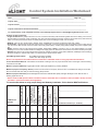
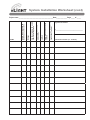
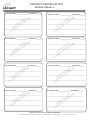
900 Northrop Road
Wallingford, CT 06492
1.800.727.7483
nLight Installation & Start-up Documentation
for
nLight Network Lighting Control System
Contents:
• nLight Installation & nSTARTUP Documentation
Details and Instructions
• nLight Control System Installation Worksheet
• nLight Project Installation Forms
• nSTARTUP Request Forms
Documents can also be downloaded from our website by going to
http://www.sensorswitch.com/nlight/docs/
www.sensorswitch.com
900 Northrop Road
Wallingford, CT 06492
1.800.727.7483
nLight Installation & Start-up Request Documentation
Details and Instructions
nLight Control System Installation Worksheet/nLight Project Installation Form/
nSTARTUP Request Form
• Must be completed and returned to [email protected] prior to
a startup being scheduled. Please see below for details.
Control System Installation Worksheet/Project Installation Form
Details (6 Pages)
•
Every nLight device with RJ-45 ports has 2 Device ID Stickers, one of which is
removable, the other stays on the device. The removable stickers will be used by
the contractor to complete the nLight Installation paperwork, see below for
details.
Project Information Section (Top of page)
• Fill out project information fields located at the top of Page 1.
nGWY Serial Number
• Place the removable Device ID sticker(s) for the Gateways(s) in the boxes
provided. If multiple Gateways are being used on the project, please provide the
ID sticker and information for each Gateway.
Device count reported by Gateway on LCD screen
• The LCD screen of the Gateway displays the # of devices the Gateways is
communicating with. The number of devices on a Gateways LCD screen should
match the total # of devices connection to that Gateway.
o All devices that have RJ-45 ports are counted, devices that do not have
RJ-45 ports (Bridge and Gateway power supplies) are not counted.
For example, if the first floor of a building has been installed with 250 nLight
devices but the LCD screen of the Gateway has only discovered 110 devices,
there is a breakdown in communication somewhere in the network and further
troubleshooting is required. If assistance is needed please contact your nLight
project manager or refer to the nLight Hardware manual for assistance.
www.sensorswitch.com
900 Northrop Road
Wallingford, CT 06492
1.800.727.7483
Number of downstream bridges
• Please record the total # of Bridges connected to each Gateway.
Every Network CAT-5A cable has been tested with a LAN cable tester & passed
• Confirm that every CAT-5 Cable has been tested with a LAN cable tester and
passed.
• The preferred CAT 5 cable pin out for the nLight network is T568B.
All devices in use have active LED’s
• Confirm that all powered devices in use have an active LED (please note
capacitive touch wall controls and devices that do not have RJ-45 ports, do not
have LED’s).
On/Off Control has been verified
• If applicable, verify all On/Off control throughout installation. Field
programming is not required for basic On/Off controls to function. This included
manual On/Off functions vial wall control, and On/Off controls via sensor
control.
Dimming Control has been verified
• If applicable, verify manual dimming functionality throughout installation. Field
programming is not required for basic ON/OFF and manual dimming controls to
function.
Gateway has a valid Ethernet connection (Link-up)
• If applicable, verify each network Gateway has its own dedicated Ethernet
connection. When properly terminated and connected to an Ethernet source,
the LCD screen will display LINK UP below the number of discovered network
devices.
Signature of Installer
• Signature of Installer in charge of nLight Installation.
Comments
• If applicable, provide additional information about Gateway (i.e. floor, location,
wing).
www.sensorswitch.com
900 Northrop Road
Wallingford, CT 06492
1.800.727.7483
Project Installation Form Details
•
•
Must be completed and returned to [email protected] prior to
a startup being scheduled. Please see below for details.
# of Project Installation Forms filled out should equal the # of Bridges installed
on a project. Copy of form also included in box Bridge is shipped in.
Bridge Serial #
• Place the removable Device ID sticker for the Bridge in the space provided. If
multiple Bridges are being used on the project, please provide the ID sticker and
information for each Bridge on separate Project Installation Forms.
Port # zone name
• Write the zone name in space provided (i.e. Room 101, Main Lobby…)
• Please indicate if the port on the Bridge is not being used (i.e. Spare, Not Used)
• Please indicate if the port on the Bridge is connected to another Bridge (i.e. to
Bridge, from Bridge)
• If the space provided is not large enough to fit all of the device ID stickers please
use the back of the form, or detail the modification made.
# of Devices
• Record the total # of devices (device with RJ-45 ports) connected to the port.
PLACE ID STICKER FOR DEVICES IN ZONE HERE
• Place the removable Device ID sticker for ALL of the zones devices in the space
provided.
www.sensorswitch.com
900 Northrop Road
Wallingford, CT 06492
1.800.727.7483
nSTARTUP Request Form Details
•
•
Must be completed and returned to [email protected] prior to
a startup being scheduled. Please see below for details.
Fill out project information fields located at the top of Page.
Special Requirements
• Complete section and provide additional information for special
requirements not listed.
nLIGHT System Training Contact
• Complete section and provide contact information for person(s) responsible
for coordinating onsite training and provide the names and titles of
individuals attending the training.
Additional programming information/ Sequence of operations for all spaces (If
Applicable)
• Provide programming information (i.e. Time based schedules/events, room
operation instructions, programming requests…)
Gateway IP Addresses
• Provide IP addresses for Gateways (if Applicable).
For additional support please call 1.800.727.7483 and ask to
speak with one of our regional nLight specialists.
www.sensorswitch.com
900 Northrop Road
Wallingford, CT 06492
1.800.727.7483
www.sensorswitch.com
Control System Installation Worksheet
Date:_________________
Field Tech: ___________________________________________ Page 1 of _____
Project name:_____________________________________________________________________________________
Project location:___________________________________________________________________________________
Project Contact Person/Contact Information:___________________________________________________________
To request Startup, send completed install form and nStartup Request form to: [email protected]
Common nLight Terminology
• nLight Control Zone: A group of devices in a room or area that are daisy-chained wired together with CAT-5 cabling. One end of a
zone should be connected to a port on a Bridge. The other end should always be left open. Devices can be wired in any order. Devices
within a zone are powered from either an nPP16 power pack or from the Bridge to which it is connected. • WallPod: A term for any nLight toggle or dimmer switch. All WallPods have model numbers that start with “nPOD”. • Power Packs: A general term for the nPP16 device that contains both a 16A line switching relay and supplies power to other devices
over the CAT-5 cable. Similar devices include: slave relay packs (nSP*), auxiliary relay packs (nAR40), and power supplies (nPS
80). • Bridge: A device used to hub several zones together. Each Bridge (nBRG*) connects to one or more other Bridges or a single
Gateway to form a communication backbone. Bridges also supply power to downstream zones that do not have an nPP16 power pack
• Gateway: The device in an nLight network that connects the network of sensors, power packs, WallPods, and Bridges to the building’s
Ethernet. Requires a network drop similar to a network printer. Model number nGWY.
CAT-5 Wiring Requirements:
RJ-45 Male Terminations (T568B)
1500 ft max cable length per zone
Notice: It is imperative that all CAT-5 cables be tested with a LAN Cable Tester to verify proper RJ-45 terminations.
Control Verification Methods: Listed below are methods of testing a zone for proper electrical control of the lights. Check all wiring
connections if test fails. Method 1 (requires WallPod): Toggle lights On/Off or dim lights Up/Down by pressing WallPod. Method
2 (requires
Sensor): Vacate zone and wait for occupancy sensor to time-out. Default time delay is 10 minutes.
Occupancy
Note sound will reset time delay on dual technology (PDT) sensors.
Method 3 (requires Photocell): Shine flashlight into Photocell. LED will blink rapidly and lights will begin to dim. After 20 min of
blinking, lights will turn off.
• Notice: Product LEDs provide status information. Refer to individual device instruction cards (included in boxes) for more
information. (www.sensorswitch.com/nlight/docs)
DIMMING*
Gateway has a valid
Ethernet connection
(Link-Up)
Signature of Installer
Dimming Control has
been verified
On / Off Control has been
verified
All Devices in use have
active LEDs
Every Network CAT-5
cable has been tested
with a LAN cable tester &
passed
Number of downstream
Bridges
nGWY Serial
Number
Device count reported by
Gateway on LCD screen
Fill out the table below to verify proper Bridge and Gateway Installation. Entire Section MUST be filled out
X_____________________________________
Comments /Location (i.e. 1st Floor)
TEMP/HUMIDITY
900 Northrop Road, Wallingford, CT 06492 • 1.800.PASSIVE • FX 203.269.9621 • www.sensorswitch.com
System Installation Worksheet (cont)
Gateway has a valid Ethernet
connection (Link-Up)
Dimming Control has been
verified
On / Off Control has been
verified
All Devices in use have
active LEDs
Every Network CAT-5 cable
has been tested with a LAN
cable tester & passed
Number of downstream
Bridges
nGWY
Device count reported by
Gateway on LCD screen
Project name __________________________________________Date_____________ Page ____ of _____
Signature of Installer
X_____________________________________
Comments /Location (i.e. 1st Floor)
900 Northrop Road, Wallingford, CT 06492 • 1.800.PASSIVE • FX 203.269.9621 • www.sensorswitch.com
PROJECT INSTALLATION
BRIDGE SERIAL # ________
Port 1 zone name:___________________ # of devices_____
E
Port 5 zone name:___________________ # of devices_____
E
_____________________________________________
ER ER
R
_____________________________________________
ER
KE
_____________________________________________
_____________________________________________
CK E H
N
ID N ZO
_____________________________________________
E
I
AC ES
L
P VIC
_____________________________________________
DE
R
FO
I
ST
Port 2 zone name:_________________ # of devices______
E
IC E H
ST ON
ID N Z
_____________________________________________
E
I
C
S
A
E
PL VIC
_____________________________________________
DE
R
FO
Port 6 zone name:_________________ # of devices_______
E
H
K
IC E
ST ZON
_____________________________________________
ID
E S IN
C
LA ICE
P
V
_____________________________________________
DE
R
FO
_____________________________________________
ER ER
_____________________________________________
ER ER
_____________________________________________
_____________________________________________
CK
H
I
E
ST ON
D
Z
I
_____________________________________________
E
IN
C
S
A
E
PL VIC
_____________________________________________
DE
R
FO
Port 3 zone name:_________________ # of devices ______
RE
R
IC E
ST ZON
ID
_____________________________________________
E S IN
C
E
A
PL VIC
_____________________________________________
DE
R
FO
Port 7 zone name:_________________ # of devices_______
E
_____________________________________________
KE HE
_____________________________________________
ER ER
_____________________________________________
_____________________________________________
Port 4 zone name:__________________ # of devices______
R
RE
IC E
ST ON
ID N Z
_____________________________________________
E
I
C
S
A
E
L
P VIC
_____________________________________________
DE
R
FO
CK
H
I
E
ST ON
ID N Z
_____________________________________________
E
I
C
S
A
E
L
P VIC
_____________________________________________
DE
R
FO
Port 8 zone name:__________________ # of devices______
E
_____________________________________________
KE HE
_____________________________________________
ER ER
_____________________________________________
_____________________________________________
CK
H
I
E
ST ON
ID N Z
_____________________________________________
E
I
C
S
A
E
PL VIC
_____________________________________________
DE
R
FO
ADDITIONAL SPACE ON OTHER SIDE IF NEEDED
900 Northrop Road, Wallingford, CT 06492 • 1.800.PASSIVE • FX 203.269.9621 • www.sensorswitch.com
PROJECT INSTALLATION
BRIDGE SERIAL # ________
Port 1 zone name:__________________# of devices_______
Port 5 zone name:________________ # of devices_______
_____________________________________________
RE
R
_____________________________________________
KE HE
_____________________________________________
_____________________________________________
E
E
CK E H
I
ST ZON
_____________________________________________
D
I
E S IN
C
E
A
PL VIC
_____________________________________________
DE
R
FO
Port 2 zone name:_________________ # of devices_______
E
_____________________________________________
ER ER
R
RE
IC E
ST ON
ID N Z
_____________________________________________
E
I
C
S
A
E
L
P VIC
_____________________________________________
DE
R
FO
Port 6 zone name:_________________ # of devices______
_____________________________________________
R
RE
_____________________________________________
E
E
CK E H
I
N
ST
_____________________________________________
ID N ZO
CE S I
A
E
PL VIC
_____________________________________________
DE
R
FO
_____________________________________________
Port 3 zone name:_________________# of devices_______
Port 7 zone name:__________________# of devices ______
H
K
IC NE
T
S O
ID IN Z
_____________________________________________
E
AC ES
PL VIC
_____________________________________________
DE
R
FO
E
ER HER
K
_____________________________________________
IC E
ST ZON
ID
E S IN
_____________________________________________
C
E
A
PL VIC
DE
_____________________________________________
R
FO
R ERE
E
_____________________________________________
H
K
IC NE
T
S
D N ZO
I
_____________________________________________
I
E
AC CES
L
P VI
_____________________________________________
DE
R
FO
_____________________________________________
_____________________________________________
Port 4 zone name:_________________ # of devices_______
RE
ER E
I
ST ZON
ID
E S IN
_____________________________________________
C
E
A
PL VIC
DE DIMMING*
_____________________________________________
R
FO
Port 8 zone name:_________________ # of devices______
E
H
K
IC E
ST ZON
ID
_____________________________________________
E S IN
C
E
A
PL VIC TEMP/HUMIDITY
_____________________________________________
DE
R
FO
_____________________________________________
CK E H
_____________________________________________
ER ER
_____________________________________________
_____________________________________________
ADDITIONAL SPACE ON OTHER SIDE IF NEEDED
900 Northrop Road, Wallingford, CT 06492 • 1.800.PASSIVE • FX 203.269.9621 • www.sensorswitch.com
nSTARTUP REQUEST
Project name:______________________________________________________________ Date:__________________
Project address:___________________________________________________________________________________
Date(s) Requested*:______________________________________ Time(s) Requested:_________________________
*Note: General lead time is 2 weeks upon approval of nSTARTUP request and required Installation Worksheet
Please email nSTARTUP Request Form along with Completed nLight Installation Worksheet to [email protected]
**Please see Terms and Conditions for nSTARTUP details
Electrical Contractor Company Name:_________________________________________________________________
Contact Information of EC that will be present during startup:
Name:____________________________________________
Phone #:__________________________________________ Email address:___________________________________
• Special requirements:
Hard hat
Steel toed boots
Safety glasses
Safety vest
Background check
Working outside of normal business hours?Y/N _____ If so, what hours are required?_____________________________
Other ___________________________________________________________________________________________
nLight System Training Contact:
Phone #:__________________________________________ Email address:__________________________________
Is the host computer/server on premises? Y/N _____ Does host server meet all Minimum OS requirements? Y/N _______
Has SensorView software been installed? Y/N _____ If No, who should be contacted to discuss?____________________
*SensorView user manual can be found by visiting, http://www.sensorswitch.com/nlight/docs/SensorView_Manual.pdf
*SensorView Installation Instructions and OS requirements can be found in the Appendix, Page 1.
Trainees:
Name/Title______________________________________
Name/Title______________________________________
Name/Title______________________________________
Name/Title______________________________________
Name/Title______________________________________
Name/Title______________________________________
Additional programming information / Sequence of operation for all spaces (If Applicable):
_________________________________________________________________________________________________
_________________________________________________________________________________________________
_________________________________________________________________________________________________
_________________________________________________________________________________________________
_________________________________________________________________________________________________
TEMP/HUMIDITY
DIMMING*
_________________________________________________________________________________________________
Gateway IP Addresses:
_______________
_______________
_______________
_______________
______________
900 Northrop Road, Wallingford, CT 06492 • 1.800.PASSIVE • FX 203.269.9621 • www.sensorswitch.com
Revised 08.09.10 © 2010 Sensor Switch
nSTARTUP Terms & Conditions
nSTARTUP [max # days]:
• One on-site visit of a predetermined maximum number of consecutive days by a certified nLight Startup Agent during
normal business hours.
• Visit must be scheduled two weeks in advance (nLight Installation Worksheets required prior to scheduling startup visit).
• Completed nLight Installation Worksheet required prior to scheduling startup visit. Worksheet must be completed by
electrical contractor and can be downloaded from:
http://www.sensorswitch.com/nlight/docs/nLight_Installation_Worksheet.pdf
• Accuracy of worksheet will be verified by startup agent, who will not be held responsible for time spent troubleshooting
installation errors by electrical contractor. Sensor Switch reserves the right to back charge the contractor at the current
rate per day plus expenses for additional days spent on site troubleshooting installation errors (including, but not limited
to miswired CAT-5 terminations). If a second site visit is required, full initial daily cost will apply.
• If start-up of SensorView software is required, a host computer must be supplied and installed prior to agent visit. It is
not required that host machine be new or dedicated for SensorView, but host computer must meet minimum operating
specifications as listed in the SensorView Installation Guide. Installation Guide and SensorView User Manual are
available for download from:
http://www.sensorswitch.com/nlight/docs/install.pdf
http://www.sensorswitch.com/nlight/docs/SensorView_Manual.pdf
• Please note that SensorView requires that the following Windows components be installed prior to agent visit:
IIS (Internet Information Services)
.NET Framework
• Installation guide has details on installing these Windows components.
• If static IP addresses are required for use with Gateway devices, they must be provided to prior to arrival on site.
• Failure to complete any of these steps may result in postponement of site visit, or additional startup days to be billed. If a
second site visit is required, full initial daily cost will apply.
• Visit includes a complete system function test as well as basic system operation and maintenance instruction.
• Depending on network design, customer requests, and time limitations, tasks performed by startup agent may include the
following:
- Verify accuracy of nLight Installation Worksheet
- Install SensorView software on user supplied computer (a host computer must be on site and meet the minimum operation operation specifications)
- Verify discovery of all network devices by SensorView software
- Set-up user accounts
- Customize network device labels (if supplied)
- Edit default operation
- Perform any necessary firmware updates
- Create Groups/Profiles
- Print Inventory and Network reports
- Perform system backup
- ½ day of training of network administrator or facility management personnel on basic operation. (Additional training time or follow up training visits can be purchased separately). Prior to arrival, a list of all
attendees for training must be provided to startup agent.
• Refunds for unused days not given if startup tasks requires less than maximum number of days quoted.
nTRAINING:
• One half (1/2) day of follow up instruction by a certified nLight Startup Agent during normal business hours.
• Visits must be scheduled two weeks in advance
• Prior to arrival, a list all attendees for training must be provided to startup agent.
900 Northrop Road, Wallingford, CT 06492 • 1.800.PASSIVE • FX 203.269.9621 • www.sensorswitch.com
© 2013 Sensor Switch