1
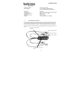
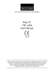
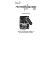
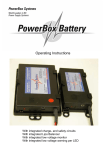
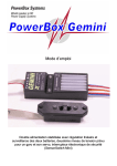
Operating Instructions
PowerBox Sensor
Dear customer, we are delighted that you have decided to purchase the POWER
BOX Sensor switch backer from our range. This is a modern, high-performance
switch system with integral battery backer for your valuable model aircraft, containing two entirely independent electronic switches in addition to the dual battery coupling facility. We have also managed to combine these features with a linear stabilised power supply voltage for receiver and servos. The linear stabilised voltage is
generated by two independent IC-controlled voltage regulators of extremely lowloss design.
The switch backer is very simple and safe in operation (the same SensorSwitch
system is used in our PowerBox “Competition” and “Champion”), but it is important
that you understand its features if you are to make best use of it. Please read
through these instructions so that you understand your new accessory fully.
We wish you much pleasure and success with your POWER BOX Sensor.
Inhaltsverzeichnis
1.
2.
3.
4.
5.
6.
1.
Product description.................................................................
Specification...........................................................................
Connections and controls .......................................................
Operating and Safety Notes.....................................................
Using the Sensor-Switch.........................................................
Guarantee conditions..............................................................
Page
Page
Page
Page
Page
Page
2
4
4
5
6
7
Product description
The POWER BOX Sensor is the world’s first switch system for small to mediumsized models which combines the functions of a battery backer, dual de-coupled
batteries, plus two independent electronic switches and two IC-controlled linear
voltage regulators, each independent of the other. Naturally, each battery can be
switched on and off separately. Our system also includes a SET button which provides an absolutely secure power-on / power-off method and protection against the
effects of vibration.
The PowerBox Sensor provides a linearly stabilised voltage of exactly 5.9 Volts
for powering your receiver and servos. This fulfils exactly the requirements of all RC
manufacturers who state a maximum permissible voltage of 6.0 Volts for their RC
components.
-2-
PowerBox Sensor
This ground-breaking overall design enables you to use the latest lightweight Lithium-Polymer cells as well as standard 5-cell NC and Hydride batteries, without
exceeding the maximum voltage of 6.0 Volts.
As you would expect, we can also supply these modern Lithium-Polymer batteries for your power supplies. We are the only manufacturer to rely exclusively upon
the Li-Po cells made by IONITY AG in Germany; we do not use any cell types
made in Asia.
The POWERBOX Sensor is equipped with LED power-on indicators for both power
circuits. If you switch one battery on, the associated green LED glows. When both
batteries are active, both LEDs light up.
The total voltage loss in the PowerBox Sensor (de-coupling diodes and voltage
regulators) is about 0.35 V, which is so low that the volume of waste heat is almost
negligible. The specified maximum continuous current is 5.0 Amps, which means
that it easily cope with 6 - 8 standard servos or 5 - 7 digital servos.
However, the rated continuous current of 5.0 A does not reflect the capacity of the
electronics; it is a function of the size of heat-sink employed. The electronic circuit is
able to handle twice the specified power without problem.
The heat-sink is mounted on the rear of the unit, and it is important to ensure that
the waste heat generated can be dissipated efficiently through this component. If
you notice that the heat-sink becomes hot in use (above 60° Celsius), this is a reliable indication that the servos you are using are consuming a disproportionate
amount of energy (power). Check your servos, linkages, pushrods etc. !
The unit features double battery and receiver cables, each with 0.34 mm² conductors. This means that voltage drop in the cables is very slight even at maximum
load.
The schematic circuit diagram below
is intended to clarify the inter-related
functions of the POWER BOX Sensor. It shows in graphic form how the
individual components are linked together.
-3-
PowerBox Sensor
2.
Specification
Operating voltage:
Power supply:
4.0 Volts to 9.0 Volts
2 x 5-cell NiCd or NiMH batteries,
or 2 x 2-cell Lithium-Polymer batteries
5.0 Amps
approx. 0.35 Volts (diode / regulator losses)
2 x 5.9 Volts (+/- 0.1 Volt)
approx. 5µA
-10°C to +75°C
35 g (complete incl. all cables)
Max. load:
Voltage loss:
Voltage stabilisation:
Idle current:
Temperature range:
Weight:
3.
Connections and controls
Connect the two batteries using the two UNI connectors. Both servo leads should
be connected to the receiver. If all the receiver servo sockets are in use, use a Ylead for the second battery connection. The second battery lead increases operational security, as the current flowing is shared between the two cables and sets of
pins.
SET button, activates a switching process
Red LED, indicates activation
Switch button, battery 1
Switch button, battery 2
2 green LEDs, indicate switch
status
-4-
PowerBox Sensor
4.
Operating and Safety Notes
Be sure to use top-quality batteries of low internal resistance to power your receiving system. Do not use receiver batteries of low capacity, as one pack may be required to provide full power to the system for the whole of a flight if the other battery
should fail.
Always use battery cells of the same type.
We recommend that you use batteries with a capacity of at least 1700 mAh; for
larger models we suggest packs of up to 3000 mAh capacity. You can use either
Nickel-Cadmium batteries (NiCd), Nickel-Metal-Hydride batteries (NiMH) or
Lithium-Polymer batteries.
We strongly recommend our own range of high-quality batteries which are designed
to be suitable for a wide range of applications in modelling.
We particularly recommend our Lithium-Polymer battery packs with integral
safety and charge electronics. These are based exclusively on the latest cells
made by IONITY AG of Germany.
In principle the POWER BOX Sensor can also be used with two separate receivers. However, please be sure to read the instructions provided by the radio manufacturer, as not all receivers work properly in tandem. In all cases the basic rule is
to keep the two receivers away from each other - they should be spaced about 25 30 cm apart inside the model.
The POWER BOX Sensor fulfils the requirements of the standard EMV directives,
as reflected by the CE symbol on the unit.
The CE symbol guarantees that the unit fulfils the statutory regulations relating to
interference-free operation. This involves checking the unit’s radiation of interference and susceptibility to outside interference. The switch backer does not suffer
interference from other electrical devices except under extremely severe conditions,
and it does not radiate interference which could affect other devices (receiver, servos).
The backer is designed exclusively for use in modelling applications and is only
approved for use in radio-controlled models.
The unit is designed for use with Direct Current power sources typified by 5-cell NC
or NiMH batteries or two-cell Lithium-Polymer batteries.
The unit must never be connected to a mains-powered PSU!
-5-
PowerBox Sensor
5.
Using the Sensor-Switch
The sensor buttons do not switch the current for the receiver and servos. The actual switching process is carried out by the two electronic switches in the POWER
BOX Sensor, which are independent of each other.
The controls on the front panel consist of three push-buttons, two green LEDs and
one red LED.
You will find two countersunk holes into which the mounting screws (supplied) fit.
These are used to attach the switch to the model.
The push-buttons are marked “SET” and “I” and “II”.
The purpose of the slightly recessed “SET” button is to prepare and execute a
switching process. Holding the “SET” button pressed in for about one second
“arms” both internal switches, and the red LED lights up. You can now switch either
or both power circuits on by pressing the other push-buttons “I” and “II”. This
method of switching allows you to check each power circuit or battery separately.
To switch off the POWER BOX Sensor, first hold the “SET” button pressed in,
then press the push-buttons “I” and “II” in turn to switch both batteries off again.
This new switching system as our own in-house development, and offers you the
highest possible standard of security.
When the electronic switches are in the “stand-by” state, i.e. the batteries are
switched off, they draw an idle current of about 5 micro-Amps. This corresponds to
a small fraction of the self-discharge rate of normal batteries.
However, if you do not intend to use your model for a long period we recommend
that you disconnect them from the POWER BOX Sensor, especially if you are using a Lithium-Polymer battery.
The POWER BOX Sensor is virtually impervious to vibration, but it is still good
practice to mount the unit in an area of the model where vibration levels are low.
Please note that the GRP fuselage sides of a power model are not suitable, as they
are always subject to considerable vibration. You can remedy the situation by cutting a ply plate (2 - 3 mm thick) about 3 cm larger than the switch aperture, and
gluing it in the appropriate position. The plate damps the vibration, and at the same
time provides plenty of “meat” into which the retaining screws of the POWER BOX
Sensor can “bite”.
-6-
PowerBox Sensor
6.
Guarantee conditions:
During the production process each PowerBox Sensor undergoes a series of
tests. We take the maintenance of the highest quality standards very seriously.
We grant a 24 month guarantee on our products, valid from the initial date of purchase. The guarantee covers proven material faults, which will be corrected by us
at no charge to you. We wish to emphasise expressly that we reserve the right to
replace the unit if a repair is impossible for economic reasons.
Repairs which our Service Department carries out for you do not extend the guarantee period.
Misuse and maltreatment, such as reversed polarity, excessive voltage, the effects of damp and fuel invalidate the guarantee. The same applies to faults which
are due to severe wear or excessive vibration.
Additional claims, e.g. for consequent damages, are excluded. We do not accept
liability for the device or the use of the device.
If you have to return the unit to us, note that we cannot accept liability for transit
damage or the loss of your shipment. If you need to make a claim under guarantee,
send the unit to us at the following address, and be sure to include proof of purchase:
Modellbau-Deutsch
Hindenburgstraße 33
86609 Donauwörth
Germany
Liability exclusion:
We are not in a position to ensure that this battery backer is operated correctly, nor
that the entire radio control system has been maintained properly.
For this reason we are unable to accept liability for loss, damages or costs which
result from the use of the PowerBox Sensor, or are connected with its use in any
way. Unless otherwise prescribed by binding law, our obligation to pay compensation, regardless of the legal argument employed, is limited to the invoice value of
those of our products which were immediately and directly involved in the event
which caused the damage.
Donauwörth, April 2004
Yours - the Modellbau-Deutsch Team
PowerBox Systems, Germany
-7-
PowerBox Sensor
PowerBox Systems
Modellbau-Deutsch
Hindenburgstraße 33
86609 Donauwörth
Tel: +49-0906-22559
Fax: +49-0906-22459
[email protected]
www.PowerBox-Systems.com
-8-